船用夹层板芯材的动态力学性能实验研究
夹层结构纸板压缩剪切性能试验研究

Abstract: Using the combination compression shear fixture by improving,shear load-displacement data of transverse and longitudinal sample for corrugated composite paperboard ( CCP) and honeycomb paperboard with the different thickness were tested and the corresponding shear strength histogram were also drawn. The results showed that: Shear resistance of longitudinal sample is greater than that of transverse sample for the sandwich structure paperboard; Under the same liner and medium,shear resistance with the same direction for the CCP and honeycomb paperboard decreases with increasing paperboard thickness,but the shear resistance of honeycomb paperboard with the same thickness and direction is larger than that of the CCP,so the entirety shear resistance of honeycomb paperboard is better than that of the CCP. The results provide the basis of compression shear for the further application of sandwich structure paperboard.
夹层板结构中的芯材性能要求和检测方法
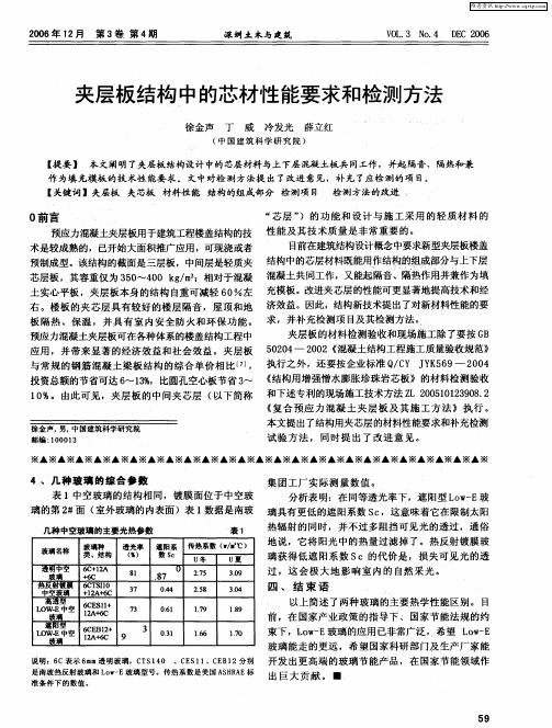
玻璃Байду номын сангаас名称
透 明中 空
表1
热 辐 射 的 同时 ,并不 过 多 阻挡 可见 光 的透 过 ,通俗 地 说 ,它将 阳光 中的热 量过 滤 掉 了 。热 反射 镀 膜玻 璃 获得 低 遮 阳 系 数 SC的代 价 是 , 损 失可 见 光 的透 过 ,这 会 极 大 地 影 响 室 内 的 自然 采 光 。
开 发 出更 高 端 的玻 璃节 能 产 品 ,在 国家节 能领 域 作
出 巨大 贡 献 。 一
L W- 空 lA 6 O E中 2 +c 7 3 玻璃 遮 阳型 6E 2 C Bl+ 3 1 1- 0 E中空 lA 6 9 w 2+C 玻璃
03 .l
16 . 6
玻 璃种 。 透 光 率 遮 阳系 传 热 系数 (/ 。 ) - -℃ 类、结构 ( %) 数 S c U冬 U夏
6 +2 C 1A
玻 璃
+C 6
8 l
.
8 7
U
25 . 7 25 .8
19 . 7
39 . 0 30 .4
19 . 8
热 反射镀 膜 6 T nO CS
维普资讯
20 年 1 月 第 3 第 4 06 2 卷 期
深圳土木与建筑
V L3 o4 DC 20 O. N . E 06
夹层板 结构 中的芯材性能要求和检测方法
徐金 声 丁 威 冷发光 薛立红
( 国建 筑 科 学研 究 院 ) 中
【 提要 】 本 文阐 明了夹层板 结构设计 中的芯层材料 与上下层 混凝 土板 共 同工作 ,并起 隔音 、隔热和兼
作 为填 充模板 的技 术性 能要 求 。丈 中对 检 测方 法提 出 了改进 意见 ,补 充 了应检 测 的项 目。 【 关键词 】夹层板 夹芯板 材料性 能 结构 的组成 部分 检 测项 目 检测 方法的改进
【技术干货】复合材料夹芯板结构的机械测试(全文典藏版)

【技术干货】复合材料夹芯板结构的机械测试(全文典藏版)本文主要介绍了碳纤维复合材料夹芯板结构的力学实验和测试方法,试验主要采用了广泛接受的军用标准(MIL-STD-401B)测试方法,主要测试内容包括如下几部分:▪长梁弯曲试验(Long Beam Flexure Test);▪▪边压试验(Edgewise Compression Test);▪▪平拉试验(Flatwise Tension Test);▪▪平压试验(Flatwise Compression Test);▪▪短梁剪切试验(Short Beam Shear Test);▪▪爬高圆筒剥离试验(Climbing Drum Peel Test)。
01 长梁弯曲试验该测试有几种可能的失效模式(见图1),一些更典型的失效模式包括皮层拉伸/压缩破坏、局部的面部起皱失效以及局部的面部缺陷。
图1 夹芯板长梁弯曲试验长梁弯曲试验的典型跨度为20英寸。
通过长梁弯曲试验,可以确定夹层抗弯强度和弯曲模量。
平均表层应力和模量可通过以下公式确定:上述计算公式适用于具有薄蒙皮结构的对称夹层板,关于试验和数据的更详细内容可参考MIL-STD-401B第5.2.4节或ASTM C-393。
02 短梁剪切试验该试验时典型跨距为4英寸(见图2)。
尽管本试验有几种可能的破坏模式,但典型的破坏模式是芯部结构破坏。
图1 夹芯板短梁剪切试验在短梁弯曲试验中,如果芯部发生破坏,则芯部抗剪强度(平均剪应力)可按下式计算:03 平压试验该试验方法主要适用于具有薄蒙皮的夹芯板结构。
有关试验和数据详细解释和讨论,可以参考MIL-STD-401B第5.2.4节或ASTM C-393。
针对夹芯板平压试验的主要目的是确定夹层板的芯部压缩性能。
本试验的典型样本为2×2英寸的面板,如图3所示。
图3 夹芯板平压试验根据测试过程中完整的荷载-挠度曲线,就可以使用以下方程式确定芯的抗压强度和抗压模量:04 平拉试验该试验目的是用于测定芯材抗拉强度或离面皮-芯粘结强度。
复合材料夹芯结构研究现状及其在船舶工程的应用
复合材料夹芯结构研究现状及其在船舶工程的应用随着人类社会的不断发展,需要快速、安全运输的需求日益增加,在船舶工程的设计中也日趋关注能够满足此需求的新型结构。
而复合材料夹芯结构正是在满足船舶工程中安全、轻质、高强度的要求的同时,具有良好的质量与成本比的全新材料成型技术。
一、复合材料夹芯结构研究现状复合材料夹芯结构由于其良好的力学性能,节省设计和制造成本,成为了船舶工程中新兴的发展方向。
从目前的研究状况来看,学者们下致力于对复合材料夹芯结构的结构本构特性、夹层传力特性及夹芯制造工艺等方面开展了大量的理论、实验研究。
其中,研究者们在结构本构特性中,将复合材料夹芯结构分解为表面层、核层和芯层,通过将夹芯材料的拉伸、剪切和压缩性能以试验方式进行研究,从而进一步探究其本构特性,形成一个完整的本构关系。
此外,研究者们还通过大量的实验,研究了夹芯结构在不同夹芯压力和负荷下的变形规律,为夹芯结构的设计提供有效的参考。
同时,研究者们也关注到了复合材料夹芯结构的夹层传力特性,进行了大量的数值分析和试验研究,发现夹层的负荷传递既受夹芯结构组合的影响,也会受外力的影响。
研究者们还从夹层传力特性的角度,研究了夹芯结构的抗震能力及耐久性。
再者,学者们也探究了复合材料夹芯结构的制造工艺,诸如热固联接技术、机械联接技术等,并进一步探讨了夹芯结构制造工艺中的参数对夹芯性能的影响。
二、复合材料夹芯结构在船舶工程中的应用随着复合材料夹芯结构技术的日趋成熟,其已经被广泛应用于船舶工程中,极大地改变了船舶工程的设计和制造。
传统的船舶结构以满足结构的强度为主,但当船舶越来越大时,其重量会极大地增加,因此复合材料夹芯结构便显示出其优势,此材料可以提供大面积、高强度、轻量的结构,节省原材料、装载空间,缩短制造周期,提高了船舶的安全与性能。
复合材料夹芯结构在船舶工程的应用大体可分为两类。
第一类是用于船舶舱室壁及底板、艏尾护墙等结构件,这些结构件具有高强度、轻重量的特点,可以大大提高船舶的质量与性能,使船舶的操纵性能更好。
钢夹层板近场水下爆炸抗爆分析及其在舰船抗爆防护中的应用

时 间耦 合 , 理论 分析 的难 度 较 大。本 文 采用 有 限元 法 , 对 质量等 效 的传 统钢 板 和钢 夹层 板 在 近场 水下 爆 炸载
S s m) yt 是一种 以钢夹 层板 为基 础 的结 构 。钢夹 层板 是 e
荷作 用下 的变形 机 制 和 吸 能 特性 进 行 分 析 , 而 为 中 进
意义 。
承担起 越来 越 多 的 近海 作 战任 务 。 因此 , 舰 船 在 近 对
海作 战的生命 力研 究也 就 显得 越 发 重要 。舰 船 在 近海 作战 的主要威 胁是 各种水 雷武 器 的攻 击 以及 恐 怖 主义 袭击 ( 如海盗 、 怖 分 子 等 自制 的漂 流 炸 弹 等 ) 由于 恐 。 濒海 战斗舰 多 为 排 水量 较 小 的 中小 型 水 面 战 斗 舰 船 , 其装 甲防护 措 施 受 排 水量 限制 不 可 能 设 计 得 很 完 善 , 传统 的防护设 计一 般仅 在 战斗 情 报 中心 、 舱 、 药库 机 弹 等核心 舱室设 置装 甲 , 它 部 位则 没 有 装 甲防 护 , 其 这使
吸能能力方 面较普通钢板具有很大优势 , 尤其是其保持 结构 完整性 的能力远强 于普通钢板 。将钢夹层板引入中小型水 面
舰 船 的舷 侧防 护改进 和设计 , 够提 高结构 的刚度 , 少结构 焊接工 作量 及焊接 变形 , 能 减 是提 高舰船 生命力 的一种有 效
手段 。
关键词 :水下爆炸 ; 夹层板 ; 钢 层薄 板 只 承受 平 面力 , 略其 本 认 忽 身 的抗 弯 刚度 , 夹心 只承 受 抗 剪作 用 , 于简 单 载荷 而 对
情况 可 以得 到夹 心 位 移 的理 论 解 。然 而 , 由于 近 场 水 下爆 炸爆炸 载荷 成分 复杂 , 荷 不仅 与 空 间有关 , 与 载 还
芯层开槽对复合夹层板力学性能的影响分析

增强技术 , 科学 、 合理 、 经济地利用该结构材料。齿
层 间应力 分 布 以及 板竖 向位 移 的影 响。与 芯层 无 开 槽情 况 的结果 相 比较 , 析 了芯 材 开 槽 对 于 防 止 面 分
层 和芯层 间剥 离的 积极 作用 。 同时研究 了沟槽 的尺
两 短边 固支 , 边 自由 , 表 面承受 竖 向均布 载荷 为 长 上
0 0 4 / 另一种 是 两长边 自由, 短边 固支 , . 0 N mm ; 一 另
本 文研 究 泡 沫 芯 材 开 槽 复 合 材 料 板 的 力 学 性 能, 将芯 层 沟槽 和 泡沫 芯材分 开 , 对芯 层开 槽 的复合
材 料夹层 板建 立 模 型 , 用 A S S进 行 弹性 分 析 。 应 NY
研 究 了芯层开 槽对 泡 沫 芯材 受 力 、 层 与 上 下 表层 芯
2 1 第 3期 00年
玻 璃 钢 /复 合 材 料
2 5
芯层 开 槽对 复 合 夹层 板 力 学 性 能 的影 响分 析
姚 秀冬 ,周 叮 ,刘 伟 庆
( 南京工业大学 土木工程学 院,南京 2 00 ) 10 9
摘要 :将芯层沟槽和 泡沫芯材分 开, 应用有限元商业软件 A S S 对芯层 开槽 的复合 材料 夹层板建立物理模型 , NY , 进行 弹性
槽 式界 面是在 芯材 的上 下 表 面 开置 正交 沟 槽 , 些 这
沟槽 填满树 脂后 将 面 板 与 芯 材 连在 一 起 , 可提 高 其
玻璃钢船体夹层结构设计(一)

中外船舶科技2020年第3期玻璃钢船体夹层结构设计(一)朱珉虎(江苏省船舶设计研究所,江苏镇江212003)摘要:随着玻璃钢船舶主尺度的增加,单板船体刚度不足的问题日趋严重。
而采用夹层结构的玻璃钢船体能够在保证与单板结构的船体相同重量的前提下使其刚度得到提高。
因此,当玻璃钢船舶的船长超过20 m时,其船体结构一般都设计为夹层结构。
夹层结构要比单板结构复杂得多。
文中计算了夹层结构的剖面模数、当量厚度等,并详细介绍了进行船体夹层结构设计时的注意事项。
关键词:玻璃钢;船体;夹层结构;设计中图分类号:U662;U668 文献标志码:A玻璃钢船体结构按外板的结构形式可分为单板结构和夹层结构两大类。
单板结构又称为“实心 结构”,是最常见的玻璃钢艇体结构形式。
因其壳 板为玻璃钢积层板,所以被称为“单板”,其内部用帽型材加强。
帽型材内部是中空的,可根据强度要求用芯材对其进行加强,外部用“n”形玻璃钢积层板黏接到艇体壳板上,构成“帽型加筋”结构。
单板 结构具有易于安装、固定各种机械设备,易于建造,造价相对较低等优点。
将玻璃钢夹层结构应用于舰 船始于20世纪60年代后期。
夹层结构(sandwich)又被称为“夹芯结构”,由上、下蒙皮和中间的芯材组成,蒙皮和芯材之间用黏合剂黏接。
夹层结构受弯矩时易产生弯曲,上、下蒙皮承受面内力(拉伸应 力或压缩应力),芯材承受剪切力。
尽管芯材的力学性能比较低,但此时整个结构的剪切强度主要由芯材承担,面板仅起部分作用。
因此,在计算其惯性 矩时,可以忽略芯材对弯曲强度的影响。
随着玻璃钢船舶尺度的增加,单板结构已不能满足需求,因此当船长超过20 m时,艇体一般采用 夹层结构。
文中对夹层结构的剖面模数、当量厚度 及夹层结构的船体设计进行了分析与研究。
1夹层结构剖面模数计算1.1夹层板剖面惯性矩图1为夹层结构的计算模型,夹层板由内蒙皮、芯材和外蒙皮构成。
图中夹层板的基线位于外蒙皮 的下平面,各型材的型心距基线的距离为 <则单位 宽度上(这里是1cm)夹层板的剖面惯性矩见表1。
聚醚胺(D230)论文:PMI泡沫壳体夹层结构设计及力学性能研究

聚醚胺(D230)论文:PMI泡沫壳体夹层结构设计及力学性能研究【中文摘要】聚甲基丙烯酸亚胺(PMI)泡沫夹层结构整体具有很高的比强度,较大的比刚度,同时还具有优异的隔热与透波功能,越来越多地应用于大型客机、火箭整流罩、载人飞船和卫星舱段等诸多技术领域。
随着航空航天科技深入发展,对于结构设计与材料的性能要求也在不断提高,使得夹层材料尤其是工艺性能十分稳定的泡沫夹层材料越来越有发展前景。
本文主要研究PMI泡沫/玻璃钢复合舱段的结构与设计优化。
首先以乙二胺为固化剂,并用D230(聚醚胺)对环氧树脂体系进行增韧改性。
纯乙二胺固化的环氧树脂为脆性材料,当加入D230以后,由于D230的C链比乙二胺长,可以有效的增加浇注体网络空间,使交联点的密度降低。
通过以上改进,制造出强度高、缺陷少、韧性好的环氧树脂浇注体。
再通过三点弯曲、拉伸等实验验证得到,当D230的比例为20%的时候,浇注体的强度达到最佳,并且达到了很好的增韧效果。
对断口进行扫描,进一步分析了D230的改性效果。
对浇注体进行了热重法(TG)试验,得到浇注体的分解温度在260℃以上,完全达到舱段的热环境使用要求。
选取聚甲基丙烯酰亚胺(PMI)作为夹层结构的芯材。
制备了PMI/玻璃钢夹层结构。
同时通过夹层结构侧压、三点弯曲等基本力学性能实验,对PMI泡沫夹层结构的力学性能进行了分析。
同时,对纤维面板铺层、PMI泡沫密度、纤维面板的厚度等影响因素进行了规律性分析。
最后,以某一型号的火箭舱段为背景,利用有限元软件Patran进行对圆柱壳和圆锥壳夹层结构进行模拟设计,并在模拟设计中对夹层结构进行了加筋处理,加大了整体的刚度。
对加筋后的夹层结构进行了屈曲分析,同时考察了面板厚度、纤维铺层角度以及PMI泡沫密度对夹层结构力学性能的影响规律。
【英文摘要】Polymethacrylimide (PMI) foam sandwich structure has high specific strengths and specific stiffness, and the excellent properties of heat insulation andwave-transparent properties, so it can be widely used in the field of large aircraft, rocket fairing, spacecraft, satellite cabin and so on. With the steady development of aerospace science and technology, the demands for structure design and properties of material are urgently increased.Foam-sandwich-structured materials with very stable process performance are very remarkable and promising in wide application field.This thesis studied the structure of PMI foam / Fiber Reinforced Plastics and optimized the design of the structure.First, 1,2-ethylenediaminem was used as curing agent, epoxy resin matrix is toughened by mixing up Polyether amines (D230). Pure ethylenediamine cured epoxy resins are brittle material.After adding D230, it can effectively increase the body casting cyberspace, and decrease the density of the crosslink, for the C-chain length of the D230 is longer thanthat of ethylenediamine. Therefore, epoxy resin matrix with low-defect, high strength and toughness could be obtained. Then the optimization quantity of the flexible amine (D230) fillings is determined through mechanical properties testing. The results shows that if quantity of the flexible amine (D230) comes up to 20%, the matrix shows the best mechanical properties.The fracture morphology was analyzed by SEM and verified the improving results with the addition of the flexible amine (D230). Then the resin casting was investigated by thermogravimetry (TG) test, its decomposition temperature is above 260℃, fully meeting the cabin thermal environment requirements.Then, PMI foam was used as the core material of sandwich structure, PMI/FRP sandwich materials are prepared. The mechanical properties of the structure are studied by lateral compression and three-pointbending experiment. Then the influencing factors of the mechanical properties of the structure are analyzed, the influence of glassepoxy thickness, the laminate orientation and the density of the PMI foam are discussed.Finally, one model rocket cabin was used as the background, simulating the sandwich of conical shell and cylindrical shell with reinforcer by the finite element software Patran and the mechanical properties are analyzed.Buckling analysis was done in reinforced sandwich structure, it also explained the effects of panel thickness, angle of fiber layer and the density of PMI foam to the mechanical properties in sandwich structures .【关键词】聚醚胺(D230) 有限元 PMI夹层结构屈曲【英文关键词】Polyether amines (D230) FEM PMI sandwich structures bulking analysis【目录】PMI泡沫壳体夹层结构设计及力学性能研究摘要3-4Abstract4第1章绪论8-20 1.1 课题背景8-10 1.2 国内外研究现状10-18 1.2.1 PMI泡沫夹层结构的特点及应用10-11 1.2.2 PMI泡沫夹层结构加筋设计研究进展11 1.2.3 PMI泡沫夹层结构的破坏模式及原因11-14 1.2.4 PMI泡沫夹层结构国内外研究现状14-15 1.2.5 夹层结构及加筋优化的国内外研究现状15-18 1.3 本文的研究内容18-20第2章测试方法及实验材料20-25 2.1 实验原材料20-22 2.2 实验内容22-25第3章环氧树脂基体制备与评价25-44 3.1 引言25 3.2 环氧树脂固化机理25-28 3.2.1 环氧树脂概述25 3.2.2 环氧树脂固化剂概述25-26 3.2.3 环氧树脂的固化机理26-28 3.3 固化剂选择方案28-32 3.3.1 固化反应的产物28-29 3.3.2 固化剂比例计算29-32 3.4 红外光谱测试32-34 3.4.1 红外光谱吸收原理32 3.4.2 红外光谱分析32-34 3.5 浇注体力学性能测试34-40 3.5.1 浇注体弯曲性能分析34-37 3.5.2 浇注体拉伸性能分析37-40 3.6 浇注体断裂性能分析40-41 3.7 浇注体热重和差热分析41-42 3.8 本章小结42-44第4章 PMI泡沫夹层结构制备及力学性能分析44-57 4.1 引言44 4.2 PMI泡沫夹层结构制备44-46 4.2.1 夹层结构面板纤维的选择44 4.2.2 夹层结构芯子的选择44-45 4.2.3 夹层结构胶黏剂的选择45 4.2.4 PMI泡沫夹层结构制作工艺45-46 4.3 PMI泡沫夹层结构弯曲性能分析46-49 4.4 PMI泡沫夹层结构侧压性能分析49-51 4.5 PMI泡沫夹层结构力学性能的影响因素51-56 4.5.1 面板厚度的影响51-53 4.5.2 面板铺层角度的影响53-55 4.5.3 PMI泡沫密度的影响55-56 4.6 本章小结56-57第5章壳体夹层结构屈曲分析57-79 5.1 引言57 5.2 夹层结构模型57-59 5.3 面板的材料常数确定59-61 5.4 夹层结构屈曲分析61-64 5.4.1 屈曲分析61-63 5.4.2 夹层结构刚度计算63-64 5.5 夹层结构加筋板的屈曲分析64-67 5.5.1 加筋结构简介64 5.5.2 模型建立64-66 5.5.3 边界条件66-67 5.6 加筋壳的屈曲分析67-72 5.6.1 蒙皮的弹性模量的修正67 5.6.2 加筋壳的屈曲计算67-72 5.7 夹层加筋结构影响因素72-76 5.7.1 面板铺层角度的影响72-74 5.7.2 加筋结构宽厚比的影响74-75 5.7.3 PMI泡沫芯子密度的影响75-76 5.8 加筋壳结构整体刚度计算76-77 5.9 本章小结77-79结论79-80参考文献80-85致谢85。
轻质夹层复合吸声结构的水声性能实验研究

动
与
冲
击
Vo. 0 13 NO 4 2 1 . 0 1
J OURNAL B OF VI RATI N O AND HOCK S
轻 质 夹 层 复 合 吸 声 结 构 的 水 声 性 能 实 验 研 究
李 浩 ,梅 志远 ,朱 锡
403 ) 30 3
夹层 复合 吸声 结 构 , 种 复 合 结 构 集 承 载 与 吸声 功 能 这 于一 体 , 有 振 动 阻 尼 性 能 好 、 低 磁 信 号 、 易 成 型 具 降 容 等优 点 , 成 为 未 来 水 下 目标 声 隐 身 研 究 的 重 要 方 将 向 。F ls 对 此 类 结 构 进 行 了介 绍 , 出 通 过 吸 od 指 声 芯料 的选择 和各 层 结 构 的 设 计 , 以得 到综 合 性 能 可
关 键 词 :复 合 材 料 ; 层 ; 心 玻 璃 微 珠 ; 学 性 能 夹 空 声
中 图分 类 号 :0 3 . 5 6 1 2+ 文 献标 识 码 :A
Unde wa e c usi a o r i s o o nd a s r i n r t r a o tc lpr pe te fa s u b o pto
高、 阻尼特 性好 、 耐腐 蚀 和抗 海 洋 生 物 侵 蚀强 等 优 良性 能, 目前 已逐渐 成 为 提 高 潜 艇 综 合 性 能 的重 要 技 术 途 径之 一 … 。用透 声性 能好 的高强 度 纤 维 增 强 复合 材 料 作面层 , 高分 子 吸声材 料 作 为 芯材 , 以制 得 三 明治 用 可
剂 : H一 5 , 京 曙 光 化 工 厂 ; 氧 固化 剂 5 3 武 汉 K 50 南 环 9: 市江北 化学试剂 厂 。在 使用 前 , 乙烯基 酯 树脂 、 氧树 环 脂 65 、 氨酯改 性 环 氧树 脂 等 进 行 真 空 除水 处 理 备 30 聚
ANSYS 夹心材料

用ANSYS解决下列问题:1、下图为一船用夹层板,上下面板与芯材粘结完好,其尺寸为:长宽均为2m,上下面板厚度均为0.1m,芯材厚度为0.25m;上下面板为钢板,其弹性模量为: E=2.06×10¹¹Pa,泊松比为0.3,密度为ρ=7850kg/m3,芯材为聚氨酯:其弹性模量为: E=1.04×10⁸Pa,泊松比为0.4, 密度为ρ=1200kg/m3,夹层板四周刚性固定,上表面受1000N/m2的均布载荷,求:(1)不受外载荷时,夹层板的前六阶自由振动频率大小;(2)受均布载荷时上、下面板的最大V on-Mises应力ANSYS程序代码:/PREP7!*ET,1,SHELL281!*KEYOPT,1,1,0KEYOPT,1,8,1KEYOPT,1,9,0!*!*MPTEMP,,,,,,,,MPTEMP,1,0MPDATA,EX,1,,2.06E11MPDATA,PRXY,1,,0.3MPTEMP,,,,,,,,MPTEMP,1,0MPDATA,DENS,1,,7850MPTEMP,,,,,,,,MPTEMP,1,0 MPDATA,EX,2,,1.04E8 MPDATA,PRXY,2,,0.4 MPTEMP,,,,,,,, MPTEMP,1,0 MPDATA,DENS,2,,1200 MPTEMP,,,,,,,, MPTEMP,1,0 MPDATA,EX,3,,2.06E11 MPDATA,PRXY,3,,0.3 MPTEMP,,,,,,,, MPTEMP,1,0 MPDATA,DENS,3,,7850 sect,1,shell,,secdata, 0.1,1,0.0,3 secdata, 0.25,2,0.0,3 secdata, 0.1,3,0.0,3 secoffset,BOT seccontrol,,,, , , , RECTNG,0,2,0,2,/DIST,1,1.08222638492,1 /REP,FAST/DIST,1,1.08222638492,1 /REP,FAST/DIST,1,1.08222638492,1 /REP,FAST/DIST,1,1.08222638492,1 /REP,FAST/DIST,1,1.08222638492,1 /REP,FAST/DIST,1,1.08222638492,1 /REP,FAST/DIST,1,1.08222638492,1 /REP,FAST/DIST,1,1.08222638492,1 /REP,FAST/DIST,1,1.08222638492,1 /REP,FAST/DIST,1,1.08222638492,1 /REP,FAST/DIST,1,1.08222638492,1 /REP,FAST/DIST,1,1.08222638492,1 /REP,FAST/DIST,1,1.08222638492,1 /REP,FAST/DIST,1,1.08222638492,1 /REP,FAST/DIST,1,1.08222638492,1 /REP,FAST/DIST,1,0.924021086472,1 /REP,FAST/DIST,1,0.924021086472,1 /REP,FASTSMRT,6SMRT,1SMRT,OFFESIZE,0.01,0, MSHAPE,0,2D MSHKEY,0!*CM,_Y,AREAASEL, , , , 1 CM,_Y1,AREA CHKMSH,'AREA' CMSEL,S,_Y!*AMESH,_Y1!*CMDELE,_Y CMDELE,_Y1 CMDELE,_Y2!*/DIST,1,0.924021086472,1 /REP,FAST/DIST,1,0.924021086472,1 /REP,FAST/DIST,1,0.924021086472,1 /REP,FAST/DIST,1,0.924021086472,1 /REP,FAST/DIST,1,0.924021086472,1 /REP,FAST/DIST,1,0.924021086472,1 /REP,FAST/DIST,1,0.924021086472,1 /REP,FAST/DIST,1,1.08222638492,1/DIST,1,1.08222638492,1 /REP,FAST/DIST,1,1.08222638492,1 /REP,FAST/DIST,1,0.924021086472,1 /REP,FAST/DIST,1,0.924021086472,1 /REP,FAST/DIST,1,0.924021086472,1 /REP,FAST/DIST,1,0.924021086472,1 /REP,FAST/DIST,1,0.924021086472,1 /REP,FAST/DIST,1,0.924021086472,1 /REP,FAST/DIST,1,0.924021086472,1 /REP,FAST/DIST,1,0.924021086472,1 /REP,FAST/DIST,1,0.924021086472,1 /REP,FAST/DIST,1,0.924021086472,1 /REP,FAST/DIST,1,0.924021086472,1 /REP,FAST/DIST,1,1.08222638492,1 /REP,FAST/DIST,1,1.08222638492,1 /REP,FAST/DIST,1,1.08222638492,1 /REP,FAST/DIST,1,1.08222638492,1 /REP,FAST/DIST,1,1.08222638492,1 /REP,FAST/DIST,1,1.08222638492,1 /REP,FAST/DIST,1,1.08222638492,1 /REP,FAST/DIST,1,1.08222638492,1 /REP,FAST/DIST,1,1.08222638492,1/DIST,1,1.08222638492,1 /REP,FAST/DIST,1,1.08222638492,1 /REP,FAST/DIST,1,1.08222638492,1 /REP,FAST/DIST,1,1.08222638492,1 /REP,FAST/DIST,1,1.08222638492,1 /REP,FAST/DIST,1,1.08222638492,1 /REP,FAST/DIST,1,1.08222638492,1 /REP,FASTACLEAR, 1/AUTO,1/REP,FASTAPLOT/DIST,1,1.08222638492,1 /REP,FAST/DIST,1,1.08222638492,1 /REP,FAST/DIST,1,1.08222638492,1 /REP,FAST/DIST,1,1.08222638492,1 /REP,FAST/DIST,1,0.924021086472,1 /REP,FAST/DIST,1,0.924021086472,1 /REP,FASTESIZE,0.04,0,CM,_Y,AREAASEL, , , , 1 CM,_Y1,AREA CHKMSH,'AREA' CMSEL,S,_Y!*AMESH,_Y1!*CMDELE,_Y CMDELE,_Y1 CMDELE,_Y2!*FINISH!*/SHRINK,0/ESHAPE,1.0/EFACET,1/RATIO,1,1,1/CFORMA T,32,0/REPLOT!*/USER, 1/VIEW, 1, -0.770722105568 , -0.360766884379 , 0.525199667863 /ANG, 1, 7.79148173320/REPLO/VIEW, 1, -0.803557991715 , -0.318335539831E-01, 0.594374611496 /ANG, 1, -36.0845017458/REPLOEPLOT/AUTO,1/REP,FAST/VIEW,1,,,1/ANG,1/REP,FAST/VIEW,1,1,2,3/ANG,1/REP,FAST/VIEW,1,1,1,1/ANG,1/REP,FAST/VIEW,1,1,2,3/ANG,1/REP,FAST/AUTO,1/REP,FAST/SHOW,JPEG,,0JPEG,QUAL,75,JPEG,ORIENT,HORIZJPEG,COLOR,2JPEG,TMOD,1/GFILE,2400,!*/CMAP,_TEMPCMAP_,CMP,,SA VE/RGB,INDEX,100,100,100,0/RGB,INDEX,0,0,0,15/REPLOT/CMAP,_TEMPCMAP_,CMP /DELETE,_TEMPCMAP_,CMP /SHOW,CLOSE/DEVICE,VECTOR,0!*APLOT/VIEW,1,,,1/ANG,1/REP,FAST/DIST,1,1.08222638492,1/REP,FAST/DIST,1,1.08222638492,1/REP,FAST/DIST,1,1.08222638492,1/REP,FAST/DIST,1,1.08222638492,1/REP,FAST!*/SHRINK,0/ESHAPE,0.0/EFACET,1/RATIO,1,1,1/CFORMA T,32,0/REPLOT!*/DIST,1,1.08222638492,1/REP,FAST/DIST,1,1.08222638492,1/REP,FAST/DIST,1,1.08222638492,1/REP,FAST/DIST,1,0.924021086472,1/REP,FAST/DIST,1,0.924021086472,1/REP,FAST/DIST,1,0.924021086472,1/REP,FAST/DIST,1,0.924021086472,1/REP,FAST/DIST,1,0.924021086472,1/REP,FAST/AUTO,1/REP,FAST/DIST,1,1.08222638492,1/REP,FAST/DIST,1,1.08222638492,1/REP,FAST/DIST,1,1.08222638492,1/REP,FAST/DIST,1,0.924021086472,1/REP,FASTEPLOT/AUTO,1/REP,FAST/DIST,1,1.08222638492,1/REP,FAST/DIST,1,1.08222638492,1/REP,FAST/DIST,1,1.08222638492,1/REP,FAST/DIST,1,1.08222638492,1/REP,FAST/DIST,1,1.08222638492,1/REP,FAST/DIST,1,1.08222638492,1/REP,FAST/DIST,1,0.924021086472,1/REP,FAST/DIST,1,0.924021086472,1/REP,FAST/PREP7FINISH/SOLFLST,2,4,4,ORDE,2FITEM,2,1FITEM,2,-4!*/GODL,P51X, ,ALL,/SHOW,JPEG,,0JPEG,QUAL,75,JPEG,ORIENT,HORIZJPEG,COLOR,2JPEG,TMOD,1/GFILE,2400,!*/CMAP,_TEMPCMAP_,CMP,,SA VE /RGB,INDEX,100,100,100,0/RGB,INDEX,0,0,0,15/REPLOT/CMAP,_TEMPCMAP_,CMP/DELETE,_TEMPCMAP_,CMP /SHOW,CLOSE/DEVICE,VECTOR,0!*!*ANTYPE,2!*!*MODOPT,LANB,6EQSLV,SPARMXPAND,0, , ,0LUMPM,0PSTRES,0!*MODOPT,LANB,6,0,10000, ,OFF /STA TUS,SOLUSOLVEFINISH/POST1SET,LISTFINISH/PREP7FINISH/SOL!*ANTYPE,0FLST,2,1,5,ORDE,1FITEM,2,1/GOFLST,2,1,5,ORDE,1FITEM,2,1/GO!*SFA,P51X,1,PRES,-1000/DIST,1,0.924021086472,1/REP,FAST/DIST,1,0.924021086472,1/REP,FAST/DIST,1,1.08222638492,1/REP,FAST/DIST,1,1.08222638492,1/REP,FAST/USER, 1/VIEW, 1, -0.410941987557 , -0.656024199701 , 0.633055236349 /ANG, 1, 10.8366873909/REPLO/AUTO,1/REP,FAST/DIST,1,1.08222638492,1/REP,FAST/DIST,1,1.08222638492,1/REP,FAST/DIST,1,1.08222638492,1/REP,FAST/DIST,1,0.924021086472,1/REP,FAST/DIST,1,0.924021086472,1/REP,FAST/DIST,1,1.08222638492,1/REP,FAST/DIST,1,1.08222638492,1/REP,FAST/DIST,1,1.08222638492,1/REP,FAST/DIST,1,0.924021086472,1/REP,FAST!*/SHRINK,0/ESHAPE,1.0/EFACET,1/RATIO,1,1,1/CFORMA T,32,0/REPLOT!*EPLOT/DIST,1,1.08222638492,1/REP,FAST/DIST,1,1.08222638492,1/REP,FAST/DIST,1,1.08222638492,1/REP,FAST/DIST,1,0.924021086472,1/REP,FAST/DIST,1,0.924021086472,1/REP,FAST/DIST,1,0.924021086472,1/REP,FAST/DIST,1,1.08222638492,1/REP,FAST/DIST,1,1.08222638492,1/REP,FAST/USER, 1/VIEW, 1, -0.784164595131 , -0.618188717911 , -0.541165112562E-01 /ANG, 1, 48.0317425267/REPLO/VIEW, 1, -0.331823627523 , -0.313773573948 , -0.889628700363/ANG, 1, 70.2006663953/REPLO/VIEW,1,1,1,1/ANG,1/REP,FAST/VIEW,1,1,1,1/ANG,1/REP,FAST/VIEW,1,1,2,3/ANG,1/REP,FAST/VIEW,1,,,1/ANG,1/REP,FAST/VIEW,1,1/ANG,1/REP,FAST/VIEW,1,,1/ANG,1/REP,FAST/VIEW,1,-1/ANG,1/REP,FAST/VIEW,1,,-1/ANG,1/REP,FAST/VIEW,1,1,2,3/ANG,1/REP,FAST/VIEW,1,,,1/ANG,1/REP,FAST/AUTO,1/REP,FAST/DIST,1,1.08222638492,1/REP,FAST/DIST,1,1.08222638492,1/REP,FAST/DIST,1,1.08222638492,1/REP,FAST/DIST,1,1.08222638492,1/REP,FAST!*/SHRINK,0/ESHAPE,0.0/EFACET,1/RATIO,1,1,1/CFORMA T,32,0/REPLOT!*/AUTO,1/REP,FAST/USER, 1/VIEW, 1, -0.723838908191 , -0.351366691430 , 0.593800204734 /ANG, 1, 12.8845585590/REPLO/AUTO,1/REP,FAST/DIST,1,1.08222638492,1/REP,FAST/DIST,1,1.08222638492,1/REP,FAST/DIST,1,1.08222638492,1/REP,FAST/VIEW,1,,,1/ANG,1/REP,FAST/AUTO,1/REP,FAST/DIST,1,1.08222638492,1/REP,FAST/DIST,1,1.08222638492,1/REP,FAST/DIST,1,1.08222638492,1/REP,FAST/DIST,1,1.08222638492,1/REP,FAST/DIST,1,1.08222638492,1 /REP,FASTFLST,2,1,5,ORDE,1 FITEM,2,1 SFADELE,P51X,1,PRES /AUTO,1/REP,FAST/DIST,1,1.08222638492,1 /REP,FAST/DIST,1,1.08222638492,1 /REP,FAST/DIST,1,1.08222638492,1 /REP,FAST/DIST,1,1.08222638492,1 /REP,FASTFLST,2,1,5,ORDE,1 FITEM,2,1/GO!*SFA,P51X,1,PRES,-1000 /VIEW,1,1,2,3/ANG,1/REP,FAST/VIEW,1,1,1,1/ANG,1/REP,FAST/VIEW,1,,,1/ANG,1/REP,FAST/VIEW,1,1,2,3/ANG,1/REP,FAST/VIEW,1,1,1,1/ANG,1/REP,FAST/VIEW,1,1,2,3/ANG,1/REP,FAST/VIEW,1,,,1/ANG,1/REP,FASTFLST,2,1,5,ORDE,1 FITEM,2,1 SFADELE,P51X,1,PRES/REP,FAST/DIST,1,1.08222638492,1 /REP,FAST/DIST,1,1.08222638492,1 /REP,FAST/DIST,1,1.08222638492,1 /REP,FAST/DIST,1,1.08222638492,1 /REP,FAST/VIEW,1,1,2,3/ANG,1/REP,FAST/VIEW,1,1,1,1/ANG,1/REP,FAST/VIEW,1,1,2,3/ANG,1/REP,FAST/VIEW,1,1,1,1/ANG,1/REP,FAST/AUTO,1/REP,FAST/DIST,1,1.08222638492,1 /REP,FAST/DIST,1,1.08222638492,1 /REP,FAST/DIST,1,0.924021086472,1 /REP,FASTFLST,2,1,5,ORDE,1 FITEM,2,1/GO!*SFA,P51X,1,PRES,-1000 !*/SHRINK,0/ESHAPE,1.0/EFACET,1/RATIO,1,1,1/CFORMA T,32,0/REPLOT!*/VIEW,1,,,1/REP,FAST/VIEW,1,1,2,3/ANG,1/REP,FAST/VIEW,1,1,1,1/ANG,1/REP,FAST!*/SHRINK,0/ESHAPE,0.0/EFACET,1/RATIO,1,1,1/CFORMA T,32,0/REPLOT!*FLST,2,1,5,ORDE,1FITEM,2,1SFADELE,P51X,1,PRES/AUTO,1/REP,FASTFLST,2,1,5,ORDE,1FITEM,2,1/GO!*SFA,P51X,1,PRES,-1000/SHOW,JPEG,,0JPEG,QUAL,75,JPEG,ORIENT,HORIZJPEG,COLOR,2JPEG,TMOD,1/GFILE,2400,!*/CMAP,_TEMPCMAP_,CMP,,SA VE /RGB,INDEX,100,100,100,0/RGB,INDEX,0,0,0,15/REPLOT/CMAP,_TEMPCMAP_,CMP/DELETE,_TEMPCMAP_,CMP/SHOW,CLOSE/DEVICE,VECTOR,0!*/STA TUS,SOLUSOLVE/SHOW,JPEG,,0JPEG,QUAL,75,JPEG,ORIENT,HORIZJPEG,COLOR,2JPEG,TMOD,1/GFILE,2400,!*/CMAP,_TEMPCMAP_,CMP,,SA VE /RGB,INDEX,100,100,100,0/RGB,INDEX,0,0,0,15/REPLOT/CMAP,_TEMPCMAP_,CMP/DELETE,_TEMPCMAP_,CMP/SHOW,CLOSE/DEVICE,VECTOR,0!*/DIST,1,0.924021086472,1/REP,FAST/DIST,1,1.08222638492,1/REP,FASTFINISH/POST1!*/EFACET,1PLNSOL, S,EQV, 0,1.0/VIEW,1,,,1/ANG,1/REP,FAST/DIST,1,1.08222638492,1/REP,FAST/DIST,1,1.08222638492,1/REP,FAST/AUTO,1/REP,FAST/AUTO,1/REP,FAST/DIST,1,1.08222638492,1/REP,FAST/DIST,1,1.08222638492,1/REP,FAST/DIST,1,1.08222638492,1/REP,FAST/DIST,1,1.08222638492,1/REP,FAST/DIST,1,0.924021086472,1/REP,FAST/DIST,1,1.08222638492,1/REP,FAST/DIST,1,1.08222638492,1/REP,FAST/USER, 1/VIEW, 1, -0.236977311539 , -0.923624330191 , 0.301263755694 /ANG, 1, 18.5539719832/REPLO/VIEW,1,,,1/ANG,1/REP,FAST!*/SHRINK,0/ESHAPE,1.0/EFACET,1/RATIO,1,1,1/CFORMA T,32,0/REPLOT!*/AUTO,1/REP,FAST/DIST,1,1.08222638492,1/REP,FAST/DIST,1,1.08222638492,1/REP,FAST/DIST,1,1.08222638492,1/REP,FAST/DIST,1,1.08222638492,1/REP,FAST/USER, 1/VIEW, 1, -0.530894128243 , -0.662507909078 , 0.528426622160 /ANG, 1, 17.6531107852/REPLO/VIEW,1,,,-1/ANG,1/REP,FAST/VIEW,1,,1/ANG,1/REP,FAST/VIEW,1,1/ANG,1/REP,FAST/ANG,1/REP,FAST/VIEW,1,1,2,3/ANG,1/REP,FAST/VIEW,1,1,1,1/ANG,1/REP,FAST/VIEW,1,1,2,3/ANG,1/REP,FAST/DIST,1,1.08222638492,1/REP,FAST/DIST,1,0.924021086472,1/REP,FAST/SHOW,JPEG,,0JPEG,QUAL,75,JPEG,ORIENT,HORIZJPEG,COLOR,2JPEG,TMOD,1/GFILE,2400,!*/CMAP,_TEMPCMAP_,CMP,,SA VE /RGB,INDEX,100,100,100,0/RGB,INDEX,0,0,0,15/REPLOT/CMAP,_TEMPCMAP_,CMP/DELETE,_TEMPCMAP_,CMP/SHOW,CLOSE/DEVICE,VECTOR,0!*SA VEFINISH! /EXIT,NOSAV几何图米塞斯应力图。
泡沫玻璃钢夹层结构板的弯曲强度分析
卢 — — 系 数 , 卢 = 0 . 1 5 8 — 0 . 1 1 《 ) 。
其 中: 0 ——板格的长边长度 , m, 当板格 的短边与
长边 比b / a小 于 0 . 3时 , 取 = 0 . 1 2 5 。
第一作者简介 : 王
泡沫玻璃钢夹层结构板 的弯 曲强度 分析—— 王
娜, 肖渤舰 , 肖曙 明
料, 环 氧树 脂 作 为 基 体 。根 据 R e i s s n e r理论 将 夹 层 板 的面 板模 拟 为 板 单 元 。E 为 纤 维 的 轴 向方 向, E 为垂 直 于 纤 维 轴 向 的方 向 , 从 其 性 能 特 点 看, 该板 为 2 D正交 异 性单 向板 , 所 以在 P a t r a n中 定义 单 向板 为 2 D O r t h o t r o p i c材 料 , 在 创 建 材 料 时, 输人 材料 的线 弹性 属性 , 由于 目前纤 维增 强塑 料船 的层 板 主要 采用无 捻 粗纱状 胶 正交 纤维 布制 作且 工艺 要求 纤 维方 向应 与船 长 ( 和船宽 ) 方 向一 致 4 J 。故本 文实例 中弹性 模量 E = E 2 =1 1 G P a , 剪切模量 G =1 0 G P a , 泊松 比 := 0 . 2 5 。由于是 研 究板 的弯 曲 , 故 可认 为 G 2 3=G =o 。, 即认 为剪 应变 , = 。 =0 。夹心 层 为泡 沫 根据 R e i s s n e r 理
夹层 结构 的适 用 理 论 和 有 限元 分 析 方 法 进 行 阐 述, 并 用解 析方 法对 比验证其 正 确性 , 通过 有 限元 分析 方法 推导 泡沫 夹层 结构 板 的边界 条件 修正 系
浅谈夹层板的力学原理及结构参数的估算

曲 面 。 凹 面 的 面 板 沿 板 面 方 向 受压 , 生 压 应 力 , 呈 产 呈 凸 面 的 面 板 沿 板 面 方 向 受 拉 , 生 拉 应 力 。 由于 产 芯 层 的 材 质 较 软 , 故 可 忽 略 其 沿 板 平 面 方 向 的 应
不 管 是 开 发 夹 层 板 新 品 种 , 是 为 满 足 客 户 的 还
特殊 需 求 , 我们 常 常需要 进行 夹层板 的设计 。 诚然 ,
从 力学 角度 对 夹 层 结构 进 行 严谨 缜 密 分 析 的 文 献 不算 少 , 计算 公式 冗长 复杂 , 但 不便 实际 使用 。 感谢 夹层 结构 的设计 师们 , 据长 期 实践 经验 绘 制 出了 根
M一 作用 于梁 横截 面 上 的弯矩
37
面 板 中性 轴
芯 层
t y
面板
a实 际 截 面
b工字 形 等 效 截 面
图 2夹 层 板 的 横 截 面
夹层板 的最 大 特点 就 是 比抗 弯 刚度 大 , 因而常
用 的
被用 来承 受产 生 弯 曲变形 的垂直 载 荷 。 四边 简 支 , 上 下面 板 同材质 等厚 度 的矩 形 夹层 板 , 受垂 直均 承 布载 荷 , 最常 见 的 一种 形 式 ( 筑 幕墙 面 板 即多 是 建 如此 ) 。故 就谈 一 下对 此类 夹层 板 的受 力分 析和 结 构参 数 的初步 估算 。
肃 文县 碧 口镇 51 .2地 震后 ,几 乎百 分 之百 房屋 倒
塌 或损 毁 , 一 栋 二层 民房 却 毫发 未 损 , 说 与 其 而 据
屋面 、 墙体 采用 轻质 、 弹性 材料 不 无关 系。 质材 料 轻 即使 坠落 , 对人 的伤 害也较 小 。 广州市 奥雅 雷诺 贝尔铝 业有 限公 司 , 一 家专 是Fra bibliotek李 睐
《夹层板在磁场中的非线性随机振动》范文

《夹层板在磁场中的非线性随机振动》篇一一、引言随着现代科技的发展,夹层板在多种工程领域中得到了广泛的应用。
尤其当夹层板在磁场中工作时,其动力学特性及非线性随机振动行为成为了一个重要的研究课题。
本文旨在研究夹层板在磁场中的非线性随机振动现象,并深入探讨其产生机理和影响因素。
二、夹层板结构及特性夹层板由面板和芯材组成,具有质量轻、强度高、刚度大等优点。
面板通常采用高强度材料,如铝合金或复合材料,而芯材则采用轻质材料,如泡沫或蜂窝结构。
这种结构使得夹层板在承受外力时具有较好的抗弯、抗剪和抗冲击性能。
三、磁场对夹层板的影响当夹层板处于磁场中时,其内部的电荷分布和电磁场相互作用会产生洛伦兹力。
这种力会改变夹层板的振动特性,导致其产生非线性随机振动。
此外,磁场还会影响夹层板的热传导性能和电性能,进一步影响其振动特性。
四、非线性随机振动的产生机理夹层板在磁场中的非线性随机振动主要由两部分组成:一是由于洛伦兹力引起的振动;二是由于外部激励(如风、雨、地震等)引起的振动。
这两种振动相互耦合,导致夹层板产生复杂的非线性随机振动。
此外,夹层板的材料特性、结构参数以及磁场强度等因素也会对非线性随机振动的幅度和频率产生影响。
五、影响因素及实验研究影响夹层板在磁场中非线性随机振动的因素众多,包括磁场强度、频率、方向,以及夹层板的材料、结构、尺寸等。
为了深入研究这些因素对非线性随机振动的影响,我们进行了大量的实验研究。
通过改变磁场参数和夹层板的参数,观察其振动特性的变化,从而得出一些有意义的结论。
六、数值模拟与分析为了更准确地描述夹层板在磁场中的非线性随机振动,我们采用了数值模拟的方法。
通过建立合理的数学模型,模拟夹层板在磁场中的振动过程,并与实验结果进行对比。
结果表明,数值模拟能够较好地反映夹层板的非线性随机振动特性。
通过对模拟结果的分析,我们可以更深入地了解磁场对夹层板振动特性的影响机制。
七、结论与展望通过本文的研究,我们得出以下结论:夹层板在磁场中会产生非线性随机振动,其振动特性受磁场强度、频率、方向以及夹层板的材料、结构、尺寸等因素的影响。
《夹层板在磁场中的非线性随机振动》

《夹层板在磁场中的非线性随机振动》篇一一、引言在现代工程技术领域中,夹层板作为一种具有良好承载性能和轻质特性的结构材料,被广泛应用于各种工程领域。
而当夹层板处于磁场环境中时,其振动特性将受到磁场的影响,特别是在非线性随机振动方面。
本文将重点探讨夹层板在磁场中的非线性随机振动特性,分析其影响因素及变化规律,为相关工程应用提供理论依据。
二、夹层板结构特点夹层板由上下两层较薄的面板和中间较厚的芯材组成,具有较高的承载能力和较好的抗震性能。
面板通常采用高强度材料,如铝合金或碳纤维等,而芯材则多采用轻质材料,如泡沫、蜂窝纸等。
这种结构使得夹层板具有重量轻、强度高、刚度大等优点,广泛应用于航空航天、船舶、建筑等领域。
三、磁场对夹层板振动的影响当夹层板处于磁场环境中时,磁场将对夹层板的振动特性产生影响。
特别是当夹层板受到非线性随机振动时,磁场的作用将更加显著。
首先,磁场会改变夹层板材料的力学性能,如弹性模量和屈服强度等。
其次,磁场会影响夹层板结构的振动模式和频率响应。
此外,磁场还可能引起夹层板内部电磁效应的耦合作用,进一步影响其振动特性。
四、非线性随机振动的分析方法针对夹层板在磁场中的非线性随机振动问题,可采用以下分析方法:1. 数值模拟法:利用有限元软件对夹层板在磁场中的振动进行数值模拟,分析其振动特性及影响因素。
2. 实验研究法:通过实验手段对夹层板在磁场中的非线性随机振动进行观测和记录,分析其变化规律及影响因素。
3. 理论分析法:结合材料力学、弹性力学等理论,对夹层板在磁场中的非线性随机振动进行理论分析,推导其振动方程和频率响应函数。
五、影响因素及变化规律通过上述分析方法,可以得出夹层板在磁场中的非线性随机振动受以下因素影响:1. 磁场强度:随着磁场强度的增加,夹层板的振动幅度和频率将发生变化。
2. 板材厚度和刚度:板材的厚度和刚度将直接影响其在磁场中的振动特性。
3. 边界条件:边界条件的变化也会对夹层板的振动特性产生影响。
纵向循环载荷下船体板极限强度实验及其数值分析

第18卷第9期船舶力学Vol.18No.9 2014年9月Journal of Ship Mechanics Sep.2014 Article ID:1007-7294(2014)09-1100-09Experimental and Numerical Investigations on Ultimate Strength of Ship Plates under Longitudinal Cyclic LoadsYANG Ping a,b,CUI Hu-wei b,DAI Yin-ze b,ZHOU Liang b(a.Key Laboratory of High Performance Ship Technology of Ministry of Education;b.School of Transportation,Wuhan University of Technology,Wuhan430063,China)Abstract:Research on the ultimate strength behavior of ship plates under longitudinal cyclic loads is one of the basic works when studying on the hull girder’s ultimate strength under cyclic bending loads,which is meaningful to guarantee the longitudinal strength safety of ship hulls.In this paper,a series of tests to the seven square column models is carried out to simulate the ultimate strengthsof ship plates under the loads of cyclic axial compression.In addition,it conducts numerical analy-sis to these models by the nonlinear finite element analysis.The studied results indicate that ship plate’s compressive ultimate strength based on one-time collapse is the maximum of ship plates’ul-timate strength under the load of cyclic axial compression;therefore,the assessment criteria of hull girder’s ultimate strength based on one-time collapse may overestimate the load bearing capability of actual ship hull structures.The conclusions in this paper are significant to understand the hull girder’s ultimate strength under the cyclic loads and impel further study on this subject.Key words:ship plate;cyclic loads;ultimate strength;experiment;NFEACLC number:U661.72Document code:A doi:10.3969/j.issn.1007-7294.2014.09.0081IntroductionAdequate longitudinal strength of a ship is directly related to the safety of lives,properties and environment as well as the structure itself.In order to ensure enough longitudinal strength during ship operation,assessment for the ultimate strength of ship structure is significant to un-derstand its largest load bearing capacity to guide earlier ship design and later operation man-agement.As the main basic component resisting longitudinal loading,ship plates play impor-tant role in the assessment for the ultimate strength of ship structures[1].Nowadays,it is com-mon practice to assess the ship ultimate strength based on one-time collapsed method[2-6].Com-pared with one-time collapsed assessment,it is more reasonable to get the ultimate strength by accounting of accumulative plastic deformation under external cyclic loads.In1950s,some researchers raised the problem about damages of ship structures under cyclic loading.In early 1970s,Mansour and Faulkner pointed out that,since there is no any knowledge about the load-ing experience on ship and bridge,the loading path is regarded as changeable and repeatable.Received date:2014-05-05Foundation item:The National Natural Science Foundation of China(Grant No.51279150);The Fundamental Research Funds for the Central Universities(Grant No.2013-YB-027)Biography:YANG Ping(1955-),male,professor,Wuhan University of Technology,E-mail:pyangwhut@;CUI Hu-wei(1986-),male,doctoral student,Wuhan University of Technology,E-mail:hwcuiwhut@.But when this cyclic loadings have been applied on ship many times,the structure may fail for over-large deflection [7].One of these accidents is the Japanese 56340DWT bulk carrier named Onomichi that collapsed when shipping under severe sea condition in 1980.Currently used longitudinal strength gained from one-time collapsed method overestimates the actual longitu -dinal strength of ship structure,which assesses the ship longitudinal strength by the side of danger.Until now,there is not enough research on the mechanic performance of basic struc -tural component such as plates,pipes and box columns under cyclic loading.Most of the re -lated works concentrated on the civil engineering about earthquake-resistance design [8-9].By mid-1980s,Fukumoto and Kusama [10-11]analyzed the non-elastic deformation of welded box structure under cyclic loading.In 1990s,Huang [12-13]analyzed the load bearing capacity of plates under in-plane cyclic loading through theoretical and experimental investigations.When a ship confronted with large longitudinal moment resulted from severe sea condition or unreasonable cargo loading,although the moment is smaller than the one-time ultimate strength and may not result in overall collapse,the deck and/or bottom plates,which locate on outmost of the cross section,may become buckling/plastic collapse under extreme longitudinal in-plane loading.Under large and repeated longitudinal moment,with the increasing of failure structure members,overall collapse may happen on the dangerous cross section of the ship hull even the ultimate strength is less than that gained from one-time collapsed method.The study on cyclic perfor -mance of ship plates is important for further understanding of failure mechanism of ship struc -tures under cyclic bending moment.This paper investigates the ultimate strength and mechani -cal performance of ship plates by experimental and numerical ways,and some useful conclu -sions are drawn from the results.2Ultimate strength experiment of ship plates under cyclic loads2.1Square column test models for ship plateFig.1Test models of manufactured square column第9期YANG Ping et al:Experimental and Numerical Investigations …1101In conducting the ultimate strength experiment on ship plates under cyclic loads,square column test models are adopted for the purpose.The model consists of four rectangular plates welded into a column and two thick plates shrouding at column ends.Seven column models are manufactured for the series of experiments.Two steel materials of Q235and Q345are se -lected for the test models.The manufactured square column models are shown in Fig.1.2.2Tensional test of material property of steelAccording to the test standard of China GBT228-2002[14],tensional specimens have been made to gain the mechanical performance of these two steel materials.The tensional specimens 1-4are Q345with plate thickness of 3mm;tensional specimens 5-6are Q235with plate thick -ness of 4mm.The specimens are shown in Fig.2,and the tensile test device in Fig.3.2.3Model sizes and initial deflectionAfter building up the column models,the dimensions and initial deflection of the testing columns have been measured.The dimensions,initial deflections and material properties of the models are shown in Tab.l.Tab.1Dimensions and materials properties of square column modelsFig.2The tensile test specimens of steel plate Fig.3The tensile test set-up of steel plate2.4Loading and measurement on square column modelsIn the experiment,four cyclic loading processes are applied.Since it is difficult to apply large enough axial tension on the models,only cyclic axial compressions are applied.From pre -ColumnNo.a Length/mmb Width/mm t Thickness /mm D Initial deflection b /t a /b E Elastic module /GPa σv Yield strength /MPa Scolumn1Scolumn2Scolumn3Scolumn4Scolumn5Scolumn6Scolumn7478.90359.82638.91528.52479.21240.90319.96240.52178.80320.98239.72240.06239.68159.64 2.762.753.803.783.773.753.75 2.420.841.481.500.741.031.2187.1465.0284.4763.4263.6863.9142.57 1.992.011.992.202.001.012.00209.30209.30210.30210.30210.30210.30210.30361.80361.80273.30273.30273.30273.30273.301102船舶力学第18卷第9期vious studies,this cyclic compressive loading case is worse than that of cyclic tension-compres -sion loading case to the structure.The axial displacements and out-plane deflections are mea -sured by electro-mechanical dial indicator in the experiment.For the axial displacement,the measurement points are located near central points on four edges of shrouding plate;for the out-plane deflection,the measurement points are on the point having the biggest out-of-plane de -formation.All the measured data are collected in real time by a computer.The results of axial displacement and out-plane deflection are averaged before analyzing.The measurement points for axial displacement and out-plane deflection are shown in Fig.4.2.5Axial cyclic loading on square column modelsThe cycles of loading on the columns are determined as four in a complete experiment.The load-control technique is employed in the initial range of loading and the displacement-control in the neighborhood of peak load.The load-control technique is used again in the un -loading state.This loading strategy can avoid the collapse of columns to carry later loading cycle.All the loading and measured data will be stored in real time for analysis.The test set-Fig.4Measurement points for axial displacement and deflection (Scolumn1)Fig.5The test set-up of square column models Fig.6Measurement apparatus for column models第9期YANG Ping et al:Experimental and Numerical Investigations …11031104船舶力学第18卷第9期up is shown in Fig.5,and the measurement apparatus in Fig.6.3NEFA for square column models under cyclic loadingAccording to the geometrical sizes,actual thickness of steel plate and material properties of steel gained from tensional test,this paper uses ANSYS to analyze the ultimate strength of columns under cyclic loading.The shrouding plates are dealt with as rigid zones instead of mod-eling into the analysis model.Firstly,buckling analysis is performed to the analysis model to get the buckling mode.Then,the mode is expanded to actual measured initial out-plane de-flection and exerted on the column model.Displacement-control is used as the loading method to realize multi-cycle loading calculation.In the post-process,the reaction forces at rigid points(a)Final deformation of Scolumn4after test(b)Final deformation of Scolumn4by NFEA(c)Final deformation of Scolumn6after test(d)Final deformation of Scolumn6by NFEAFig.7Final deformation of models(Scolumn4and Scolumn6)are collected to gain the longitudinal force vs.shortening displacement curve.The final defor -mations of Scolumn4and Scolumn6by experiment and non-linear finite element analysis are shown in Fig.7.4Experiment and NFEA results of the square column modelsFrom the results of experiments and Non-linear FEA,the non-dimensional curve of axial load vs.shortening can be drawn in Figs.8-14.In these figures,σv is the initial yield strength of steel;εy is the initial yield strain of steel;σis the average stress of the column;εis the average strain at the ends of the column.From observation to the test models under cyclic loading process,it can reveal the reasons why the ultimate load bearing capacity of the test models will continuously reduce after every cyclic loading.a)In the cyclic loading process,these column models will go through buckleFig.8The curve of axial load vs.shorteningFig.9The curve of axial load vs.shortening (Scolumn1)(Scolumn2)Fig.10The curve of axial load vs.shorteningFig.11The curve of axial load vs.shortening (Scolumn3)(Scolumn4)第9期YANG Ping et al:Experimental and Numerical Investigations …1105and post-buckle in which material yielding will take placein the models.The material yielding will reduce the rigid -ness of the test models and hence reduce the load bear -ing capacity of the test models.b)After every unloadingamong cyclic loads,the residual out-plane deflection willaccumulate and become as the new original out-planedeflection to the next loading.This phenomenon is themain reason that causes the ultimate load bearing capac -ity of the test models decrease subsequently in cyclicloading process.The original out-plane deflection has much effect onthe compressive load bearing capacity of plates.The com -pressive ultimate strength of a plate will decrease rapidlywhen the out-deflection is over-large.5ConclusionsBoth experiments and non-linear FEA have been done on seven square column models to study the ultimate strength of ship plates under cyclic longitudinal compression.From the results of the experiments and numerical simulations,the following conclusions can be drawn:(1)From the experimental and numerical results,with the increasing of loading cycles,the compressive ultimate strength of plates keeps decreasing,and the ultimate strength in the current loading cycle is almost equal to the unloading value of the previous cycle.(2)It can be found that the ultimate strength of plates from one-time collapse has the maximum value among the whole cyclic loading process.Because the ultimate strength of ship plates under cyclic loading is related to the loading history,so the assessment criteria of one-Fig.12The curve of axial load vs.shorteningFig.13The curve of axial load vs.shortening (Scolumn5)(Scolumn6)Fig.14The curve of axial load vs.shortening (Scolumn7)1106船舶力学第18卷第9期第9期YANG Ping et al:Experimental and Numerical Investigations (1107)time collapse used for ultimate strength is unsafe to actual ships.(3)According to the experiment results,the parameter b/t has the biggest effect on the ultimate strength of ship plates.The ultimate strength may increase with the decease of b/t, while a/b and a/t have unapparent effect.(4)From the experiment phenomenon,the loading path does not coincide with the un-loading path.There is hysteresis loop between the two paths,which is related to material’s non-ideal property.In the non-linear FEA of the paper,these two paths are overlapped, which is resulted from idealized material assumption in the numerical simulation.(5)The final modes are similar to each other of the experimental test and numerical sim-ulation.From Figs.8-14,it can be seen that the trends of curves by numerical simulations a-gree well with those from experiment results.It could be noted that the NFEA results are high-er than those from experiment,the reason of this should be caused from ignoring the effect of welding residual stress in the numerical simulations.Because of constrain from the test set-up,cyclic tensional loads are not considered in this paper.The tension-compressive load bearing capacity of ship plates and stiffened panels will be dealt with and discussed in the other paper by means of box-beam models subjected to cyclic bending loads.For the consideration of the paper length,the out-plane deflection of plates is not involved in the paper.It will be discussed in another paper.References[1]Yao T,Nikolov P I.Buckling/plastic collapse of plates under cyclic loading[J].Journal of the Society of Naval Architectsof Japan,1990,168:449-462.[2]Gordo J M,Soares C G.Approximate methods to evaluate the hull girder collapse strength[J].Marine Structures,1996,9(3-4):449-470.[3]Rahman M K,Chowdhury M.Estimation of ultimate longitudinal bending moment of ships and box girders[J].Journal ofShip Research,1996,40(3):244-257.[4]Paik J K,Kim B J,Seo J K.Methods for ultimate limit state assessment of ships and ship-shaped offshore structures:PartIII hull girders[J].Ocean Engineering,2008(35):281-286.[5]Yao T,Fujikubo M,Khedmati M R.Progressive collapse analysis of a ship’s hull girder under longitudinal bending con-sidering local pressure loads[J].J Society of Naval Architects of Japan,2000,188:507-515.[6]ISSC CommitteeⅢ.1Report:Ultimate strength[C].Proceedings of the18th International Ship and Offshore StructuresCongress(ISSC),2012:285-363.[7]Evans J H.Ship Structural Design Concepts[M].Cornell Maritime Press Inc.,1983.[8]Zheng Hong.Interactive flexural-torsional buckling behavior and design criterion of I-beams and beam-columns undercyclic loading[D].Xi’an:Xi’an University of Architecture&Technology,2000.[9]Ayhan B,Jehel P,et al.Coupled damage-plasticity model for cyclic loading:Theoretical formulation and numerical im-plementation[J].Engineering Structures,2013,50:30-42.[10]Fukumto Y,Kusama H.Local instability tests of plate elements under cyclic uniaxial loading[J].Journal of StructuralEngineering Division.ASCE,1985,111(ST5):1251-1067.[11]Fukumto Y,Kusama H.Cyclic behavior of plates under in-plane loading[J].Engineering Structures,1985,7:56-63.[12]Huang Z Q.Ultimate strength of a rectangular plate under cyclic compressive and tensile loads[J].Journal of HuazhongUniversity of Science and Technology(Natural Science Edition),1994(04):36-41.(in Chinese)1108船舶力学第18卷第9期[13]Huang Z Q,Chen Q S,Luo Z Y,Kang S J.The inelastic deformation behavior of a square plate under cyclic in-planecompressive loading[J].J Huazhong University of Science and Technology,1996,24(3):39-42.(in Chinese)[14]GB/T,228-2002.Metallic materials-Tensile testing at ambient temperature[S].The national Standard of China,2002.纵向循环载荷下船体板极限强度实验及其数值分析杨平a,b,崔虎威b,戴银泽b,周亮b(武汉理工大学a.高性能舰船技术教育部重点实验室;b.交通学院,武汉430063)摘要:分析船体板在循环面内载荷下的极限强度特性,是开展船体梁循环弯曲下极限强度研究的基础工作,对于保障船舶的总纵强度安全具有重要意义。
玻璃钢复合材料船舶夹层结构中的泡沫芯材

结构泡沫芯材的历史回顾(复材在线原创文章)玻璃钢/复合材料(FRP/CM)中常用的泡沫芯材有聚氯乙烯(PVC)、聚苯乙烯(PS)、聚氨酯(PUR)、丙烯腈-苯乙烯(SAN)、聚醚酰亚胺(PEI)及聚甲基丙烯酰亚胺(PMI)等泡沫,其中PS和PUR泡沫通常仅作为浮力材料,而不是结构用途。
目前PVC 泡沫已几乎完全代替PUR泡沫而作为结构芯材,只是在一些现场发泡的结构中除外。
严格意义上讲,第一种用在承载构件夹层结构中的结构泡沫芯材是使用异氰酸酯改性的PVC泡沫,或称交联PVC。
第一个采用PVC泡沫夹芯的夹层结构是保温隔热车厢。
交联PVC的生产工艺是由德国人林德曼在上世纪30年代后期发明的。
二次大战以后法国将该工艺列入战争赔偿中,由克勒贝尔蕾洛雷特塑料公司(Kleber Renolit)开始生产Klegecell®交联PVC泡沫,主要是一些用在保温隔热车厢中的低密度产品。
上世纪50-60年代,克勒贝尔蕾洛雷特塑料公司给几家欧洲公司发放了PVC泡沫的生产许可证。
另外两家美国公司,B.F歌德雷奇(B.F Goodrich)和佳士迈威(Johns-Manville)也买到了许可证开始生产,但是几年以后就停产。
当所有的生产许可证都过期以后,交联PVC的生产工艺过程转为公开。
进入70年代以后,多数原来的欧洲许可生产厂家也已停产。
目前两个主要的生产厂家是戴博(Diab)公司的Divinycell®和Klegecell®系列PVC泡沫及爱瑞柯斯(Airex)公司的Herex®系列PVC泡沫。
20世纪40年代后期,林德曼使用高压气体作为发泡剂,制造出未经过改性的PVC泡沫,也叫线性PVC泡沫。
英国于1943年首先制成聚苯乙烯泡沫塑料,1944年美国道化学有限公司用挤出法大批量的生产聚苯乙烯泡沫塑料。
第二次世界大战期间,德国拜尔的试验人员对二异氰酸酯及羟基化合物的反应进行研究,制得了PUR硬质泡沫塑料、涂料和粘合剂。
复合材料泡沫夹层结构力学性能与试验方法

FRP /C M 2005.N o .2收稿日期:2004 07 23作者简介:孙春方(1963 ),男,副研究员,博士研究生。
复合材料泡沫夹层结构力学性能与试验方法孙春方,薛元德,胡 培(同济大学航空航天与力学学院,上海200092)摘要:本文讨论纤维增强复合材料与聚合物泡沫组成的夹层结构的刚度、强度及弯曲性能试验方法;分析了复合材料面层的弹性常数、泡沫芯层的模量和夹层结构的刚度;阐述了夹层结构的应力分布和常见的5种破坏模式;对夹层结构的疲劳强度和冲击时的力学行为进行了探讨。
关键词:复合材料;泡沫;夹层结构;力学性能中图分类号:T B332 文献标识码:A 文章编号:1003-0999(2005)02-0003-041 引 言由轻质芯体与两层刚硬坚固的外壳制成的结构件称为夹层结构。
芯体对外壳的分隔增大了结构的惯性矩,而质量几乎没增加,得到一个抗弯曲和屈曲载荷的有效结构。
它常用于为减小重量的场合。
外壳或面材一般是金属(如铝)或纤维增强复合材料,芯体是蜂窝、聚合物泡沫、木材等。
本文讨论纤维增强复合材料与聚合物泡沫组成的夹层结构。
探讨轨道车辆用复合材料泡沫夹层结构中的一些力学性能及相应的试验方法。
复合材料是由两种或两种以上不同化学性质或物理性质的组分复合而成的材料。
复合材料具有质量轻、比强高,易于加工和改型、耐腐蚀、可设计性强等优点。
涉及到的材料包括碳纤维、玻璃纤维、环氧树脂和酚醛树脂等。
聚合物泡沫是一种最常见的芯材,主要有聚氯乙烯(PVC )、聚苯乙烯(PS)、聚氨酯(PU )、聚甲基丙烯酰亚胺(P M I)、聚醚酰亚胺(PE I)和丙烯腈 苯乙烯(SAN 或AS)。
密度从30kg /m 3到300kg /m 3不等。
通常在复合材料中使用的泡沫密度在40~200kg /m 3之间。
夹层结构的力学性能取决于表层和芯部材料的力学性能及几何尺寸。
主要涉及夹层结构的强度和刚度。
强度主要指复合材料的拉、压性能,泡沫的剪切强度,夹层结构的疲劳强度和冲击时的力学行为。
- 1、下载文档前请自行甄别文档内容的完整性,平台不提供额外的编辑、内容补充、找答案等附加服务。
- 2、"仅部分预览"的文档,不可在线预览部分如存在完整性等问题,可反馈申请退款(可完整预览的文档不适用该条件!)。
- 3、如文档侵犯您的权益,请联系客服反馈,我们会尽快为您处理(人工客服工作时间:9:00-18:30)。
中 图分 类 号 : U 6 6 1 . 4
文献标识码 : A
d o i : 1 0 . 3 9 6 9  ̄ . i s s n . 1 0 0 7 — 7 2 9 4 . 2 0 1 5 . 0 7 . 0 0 9
Ex p e r i me n t a l s t u d y o n d y n a mi c me c h a n i c a l p r o p e r t i e s
c o e l a s t i c p l a s t i c i t y ma t e i r a l s b y n u me i r c a l i f t t i n g t o e x p e i r me n t l a r e s u l t s b a s e d o n Z , r I ’ n o n l i n e r a v i s c o e l a s — t i e .T h e c o mp a is r o n wi t h t h e e x p e r i me n t r e s u l t s s h o we d t h e v li a d i t y o f t h e p r o p o s e d c o n s t i t u t i v e r e l a t i o n
s ui t s we r e di s c u s s e d .A c o ns t i t ut i v e r e l a t i o n mo d e l wa s p r o po s e d f o r po l y u r e t ha n e e l a s t o me r a n d o t he r v i s -
船用夹层板芯材 的动态力学性 能实验研 究
田阿利 ,叶仁 传 ,沈超 明
( 江 苏科 技 大 学 船 舶 与 海 洋工 程 学 院 ,江 苏 镇 江 2 1 2 0 0 3 ) 摘 要 :基 于分 离 式 霍 普 金 森 压 杆 实 验 装 置 , 对 船 用 夹 层 板 系 统( s P s ) 的 芯材 一 聚氨 酯 弹 性 体 的 动 态 力 学 性 能 进 行
Ab s t r a c t : T h e d y n a mi c c o mp r e s s i v e p r o p e r t i e s o f p o l y u r e t h a n e e l a s t o me r wh i c h c a n b e u s e d a s c o r e ma t e -
s u r e b a r a t h i g h s t r a i n r a t e s . O n t h e p r e mi s e o f o n e d i me n s i o n a n d u n i f o r mi t y , t h e s t r e s s — s t r a i n r e l a t i o n s o f p o l y u r e t h a n e e l a s t o me r a r e i n v e s t i g a t e d a t d i f f e r e n t s t r a i n r a t e s a n d t h e e f f e c t s o f s p e c i me n s i z e o n t h e r e —
了实 验 分 析 。在 实 验 满 足 一 维 、 均 匀 性 的 前提 下 , 计 算 得 到 了聚 氨 酯 弹性 体 在 不 同 应 变 率 下 的应 力一 应 变 关 系 , 讨 论 了试 样 尺 寸 对 结 果 的影 响 ; 考虑聚氨酯弹性体不同于金属的动态力学性能 , 以及 准 静 态 力 学性 能 与 动 态 力 学 性 能 的差 异 , 确 定 运 用 朱一 王一 唐 ( Z WT) 方程描述聚氨酯弹性体的本构关系 , 能够准确反应 聚氨酯弹性体 的 非 线 性 粘 弹 性 特性 , 拟 合结 果 与实 验 结 果 吻 合 较好 。 关键词 : 船用夹层板 ; 聚 氨 酯 弹性 体 ;动 态力 学 性 能 ; 本 构 模 型
i r a l s o f s h i p s a n d w i c h p l a t e s s y s t e m( s P s ) w e r e e x p e i r m e n t a l l y s t u d i e d b y m e a n s o f a s p l i t Ho p k i n s o n p r e s —
第 l 9卷第 7期
2 0 1 5年 7月
文 章 编 号 :1 0 0 7 — 7 2 9 4 ( 2 0 1 5 ) 0 7 - 0 8 3 4 - 0 7
船舶 力学
J o u r n a l o f S h i p Me c h a n i c s
Vo 1 . 1 9 No . 7 J u 1 . 2 0 1 5
o O f l s S hi i l ll l p P l a t e
T I A N A- l i ,Y E Re n - c h u a n , S HEN C h a o - mi n g
( S c h o o l o f N a v a l A r c h i t e c t u r e a n d O c e a n E n g i n e e r i n g , J i a n g s u U n i v e r s i t y o f S c i e n c e a n d T e c h n o l o g y , Z h e n j i a n g 2 1 2 0 0 3 , C h i n a )