Flowserve阀门定位器
福斯FLOWSERVE阀门定位器

福斯FLOWSER阀门定位器福斯定位器配置指南福斯(FLOWSERV阀门定位器调试方法(锦菲特I3599429OO2)[Q-Q,6696 22933]flowserve 阀门、Flowserve 3400IQ 定位器、LOGIX500、LOGIX510、LOGIX520 D3系列P-5 气动定位器电动气动数字-通用,IS和EXHART、Profibus 、Foundation 现场总线反馈机组、限位开关比如PP5XX-HPGU-23K01-PV9DA-3ZPMV P-1700 系列阀门专为腐蚀或高温环境应用设计,其所有外部零件均由不锈钢制造而成。
P-1700 和1720 型阀门的内部零件采用不锈钢制造,而P-1710 和P-1730 型阀门的内部零件则采用铝制。
P-1720 和P-1730 型阀门具有超高的空气传送能力。
P-1700 系列阀门专为双向操作应用设计,不过也可通过旋动一个阀座轻松实现单向操作。
不锈钢磁场外壳内的PMV I/P转换器很容易安装在P-1700 系列阀门上。
P-1500 P-1520P-1700 P-1720P-1710 P-1730Digital 具有PID 控制的2000 数字定位器品牌Logix说明福斯Logix 2000 是一款具有板载PID 控制的数字定位器。
通信方式为4-20mA 或Modbus。
阀门上安装的PID 控制器每秒更新阀杆位置16 次,从而减少了控制系统延迟。
Logix 3200IQ 数字定位器3200IQ-10-D6-M-04-40-0G-0F 3200IQ-10-D6-M-04-40-0G-00品牌Logix说明福斯Logix 3200IQ 数字HART? 定位器使用先进的piezo 技术提供一流的性能和可靠性。
通过使用本地按钮、HART手持设备和SoftTools 软件可轻松配置Logix 3200IQ 。
LOGIX 3201IQ定位器P/N : 215809.999.000,SN 4107028LOGIX 3202IQ定位器P/N : 221734.999.000,SN 4907010LOGIX 3203IQ定位器P/N : 216428.999.000,SN 610727 定位器P/N:215809.999.000,SN:55070043400IQ Digital Positioner品牌Logix说明The Flowserve Logix 3400 Series digital Foundation? Fieldbuspositioner utilizes state-of-the-art piezo technology to provide …500 数字定位器品牌Logix说明福斯Logix 500 数字定位器是下一代本质安全型Logix 500 系列的代表。
FISHER阀门定位器介绍

产品特点和优势
高精度定位
快速响应
Fisher阀门定位器采用先进的电子技术和传 感器技术,能够实现高精度的位置控制, 确保阀门的准确开启和关闭。
定制化服务
为了满足不同客户的个性化需求,阀门定位器制造商将提供更加定制化的产品和服务。通 过与客户合作,深入了解其工艺流程和需求,为其提供定制化的阀门定位器解决方案,提 升客户满意度。
对行业的影响和价值
提高生产效率
阀门定位器在工业自动化中发挥着重 要作用,能够精确控制阀门的开度和 位置,提高生产过程的自动化水平和 效率。
市场现状
当前,Fisher阀门定位器市场呈现出稳步增 长的趋势。随着工业自动化的推进和智能制 造的兴起,阀门定位器在各种工业领域中的 应用越来越广泛,市场需求持续增长。
竞争格局
在Fisher阀门定位器市场中,存在众多国内 外品牌,竞争激烈。其中,Fisher作为一家 历史悠久的阀门定位器制造商,凭借其技术 优势和品牌影响力,占据了一定的市场份额。 其他品牌如Honeywell、Emerson等也具 备一定的竞争力。
调试方法和技巧
• 调整定位器参数:根据需要调整定位器的参数,如灵敏度、 死区等。
调试方法和技巧
技巧 在调整参数时,逐步进行,避免大幅度调整。
在调试过程中,保持稳定的气源压力。
在调试完成后,进行系统测试,确保阀门定位器工作正 常。
常见问题及解决方案
01
02
03
04
问题1
阀门无法正常关闭或打开。
Flowserve阀门定位器
YRGG stroke calibration in progress 行程整定进行中 YRGR feedback unstable while calibration 整定时反馈 不稳定 YRYG setting IL offset while calibration 整定时设置内 层偏移 YRYY no feedback motion while calibration 速写时无反 馈动作 YRYR feedback 0% out of range 反馈0不在范围内 YRRG waiting-adjust to full open position 等待调整全开 位置 YRRY feedback 100% out of range 反馈100 不在范围内 YRRR feedback span too small 反馈量程太小 RGYY pressure reading out of range 读取压力超出范围
16
RGYR loss of supply pressure 丢失电源电压(提供压 力) RGRR position deviation alert (user set ) 偏离位置报警 RYGG factory reset condition-recalibration 工厂条件下 重新设置整定条件 RYYY pneumatic relay position alert 压力继电器位置 警报 RRGG watch dog timer timeout 察看看门狗定时器输 出 RRYG internal temperature alert 内部温度报警 RRYY piezo valtage error 压力电压错误 RRYR shunt volatge reference 并联基准电压标记 RRRY nv ram checksum error 标准存储校验和错误
福斯FLOWSERVE阀门定位器调试方法
福斯FLOWSERVE阀门定位器调试方法概述:福斯FLOWSERVE阀门定位器是一种用于控制阀门开度的装置,具有自动控制和调节阀门的功能。
在使用过程中,为了确保阀门的正常运行和准确的调节效果,需要进行定位器的调试。
下面将介绍福斯FLOWSERVE阀门定位器调试的方法。
一、设备检查在调试之前,需要先对福斯FLOWSERVE阀门定位器及其相关设备进行检查,以确保设备正常运行。
检查的内容包括:1.验证设备的供电情况,检查电源是否接通、电压是否正常。
2.检查设备的接线是否正确,确认线路没有接错,并确保线缆连接牢固。
3.检查设备的传感器和执行器的连接情况,确保连接稳固可靠。
4.检查设备的控制信号输入和输出接口,确认信号的连接正确。
二、设备调整在设备检查完成之后,需要进行设备的调整,以确保设备的性能和参数达到要求。
调整的内容包括:1.调整定位器的行程范围,即设定阀门开度的上限和下限。
2.调整定位器的灵敏度,以适应不同的调节范围和工作要求。
3.调整定位器的响应时间,确保定位器对控制信号的响应及时、准确。
4.调整定位器的失控保护参数,以确保阀门在出现故障或异常情况时能够及时切断控制信号,以保护设备的安全。
三、系统调试在设备调整完成之后,需要对整个系统进行调试,以确保系统的正常运行和阀门的准确调节。
调试的内容包括:1.验证设备的基本功能,包括手动和自动控制模式的切换、阀门的开度控制等。
2.调试阀门的调节效果,包括调节灵敏度、控制精度、阀门的行程范围等。
3.验证系统的稳定性,通过观察和记录系统的运行情况,判断系统是否存在异常或故障。
4.验证系统的自动保护功能,包括失控保护、异常报警等功能的正常运行。
四、参数调整在系统调试完成之后,如果发现阀门的调节效果不理想或不满足要求,需要进行参数的调整。
调整的内容包括:1.调整PID控制器的参数,包括比例系数、积分时间和微分时间等,以改善控制效果。
2.调整定位器的灵敏度和响应时间,以适应不同的工作要求和调节范围。
福斯阀门定位器调试步骤
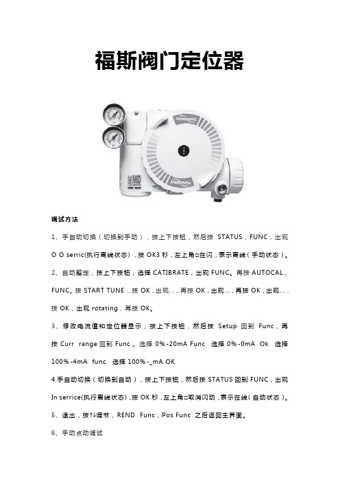
福斯阀门定位器调试方法1、手自动切换(切换到手动),按上下按钮,然后按STATUS,FUNC,出现O O serric(执行离线状态),按OK3秒,左上角□在闪,表示离线(手动状态)。
2、自动整定,按上下按钮,选择CATIBRATE,出现FUNC。
再按AUTOCAL,FUNC。
按START TUNE,按OK,出现…,再按OK,出现…,再按OK,出现…,按OK,出现rotating,再按OK。
3、修改电流值和定位器显示,按上下按钮,然后按Setup回到Func,再按Curr range回到Func。
选择0%-20mA Func 选择0%-0mA Ok 选择100%-4mA func 选择100%-_mA OK4.手自动切换(切换到自动),按上下按钮,然后按STATUS回到FUNC,出现In serrice(执行离线状态),按OK秒,左上角□取消闪动,表示在线(自动状态)。
5、退出,按↑↓调节,REND Func,Pos Func 之后返回主界面。
6、手动点动调试首先将调校DIP开关拨到Jog位置,用户只能手动设置满量程,不能设置全关位,阀门全关位为默认状态。
当DIP 开关拨到Jog位置时,定位器的二极管的状态为黄-红-红-绿。
此时用户再用Jog按钮↑↓手动调节阀门至所期望的100%,阀门到位后,同时按↑和↓按钮,这时阀门自动进行调整,等调整结束后二极管的状态回到黄-红-红-绿,再重新进行100%的设定,设定完成后,同时按↑和↓按钮,阀门进行自动调整。
调整完毕后,二极管的状态以绿色开始。
这表明手动调试完成,定位器正常。
7、就地手动操作QUICK-CAL按钮和↑和↓三个按钮同时按住三妙钟,二极管的状态黄-绿-红-红,此时松开三个按钮,就可以用↑和↓进行阀门开关操作。
按QUICK-CAL按钮即可退出手动操作,恢复自动状态。
福斯FLOWSERVE阀门定位器

福斯FLOWSERVE阀门定位器福斯定位器配置指南福斯(FLOWSERVE)阀门定位器调试方法(锦菲特I3599429OO2)[Q-Q,6696 22933]flowserve阀门、Flowserve 3400IQ定位器、LOGIX500、LOGIX510、LOGIX520、D3系列P-5 气动定位器电动气动数字 - 通用,IS 和 EXHART、Profibus、Foundation 现场总线反馈机组、限位开关比如 PP5XX-HPGU-23K01-PV9DA-3ZPMV P-1700 系列阀门专为腐蚀或高温环境应用设计,其所有外部零件均由不锈钢制造而成。
P-1700 和 1720 型阀门的内部零件采用不锈钢制造,而P-1710 和 P-1730 型阀门的内部零件则采用铝制。
P-1720 和P-1730 型阀门具有超高的空气传送能力。
P-1700 系列阀门专为双向操作应用设计,不过也可通过旋动一个阀座轻松实现单向操作。
不锈钢磁场外壳内的PMV I/P转换器很容易安装在 P-1700 系列阀门上。
P-1500 P-1520P-1700 P-1720P-1710 P-1730Digital具有 PID 控制的2000 数字定位器品牌 Logix说明福斯 Logix 2000 是一款具有板载 PID 控制的数字定位器。
通信方式为 4-20mA 或Modbus。
阀门上安装的 PID 控制器每秒更新阀杆次,从而减少了控制系统延迟。
Logix3200IQ 数字定位器 3200IQ-10-D6-M-04-40-0G-0F3200IQ-10-D6-M-04-40-0G-00品牌 Logix说明福斯 Logix 3200IQ 数字 HART? 定位器使用先进的 piezo 技术提供一流的性能和可靠性。
通过使用本地按钮、HART 手持设备和SoftTools软件可轻松配置 Logix 3200IQ。
LOGIX 3201IQ定位器 P/N:215809.999.000,SN:4107028LOGIX 3202IQ定位器 P/N:221734.999.000,SN:4907010LOGIX 3203IQ定位器 P/N:216428.999.000,SN:610727定位器 P/N:215809.999.000,SN:55070043400IQ Digital Positioner品牌 Logix说明 The Flowserve Logix 3400 Series digital Foundation? Fieldbuspositioner utilizes state-of-the-art piezo technology to provide…500 数字定位器品牌 Logix说明福斯 Logix 500 数字定位器是下一代本质安全型 Logix 500 系列的代表。
福斯中国 - Home - Flowserve Corporation
上海QRC提供多种服务,以维护机械密封件的可靠 性并提高其性能: ● 清洁设备 ● 密封表面研磨机 ● 磨损零件的维修和替换 ● 零件测试和测量设备 ● 密封件测试设备——符合API 682标准 ● 包装设备
惠州QRC
福斯惠州快速反应中心能够向最终用户提供以下 的各项服务: ● 泵的现场安装,开机以及调试 ● 泵的现场维护以及检修 ● 泵的现场对中检测以及调整 ● 泵叶轮的升级以及改造 ● 立式泵动力端的更新 ● 为福斯机械密封提供各项维修服务和升级 ● 生产福斯泵的OEM 备件 ● 为本地生产的备件提供检测报告 ● 技术支持
9
阀门部
凭借业界种类齐全的阀门、执行器、定位器、控制 器和开关产品,以及广泛的研发、工程和全球服 务,福斯为各种应用环境提供完整、周密、精益求 精的流体控制方案。
福斯阀门帮助客户提高设施运转效率,实现生产目 标。我们在化学品、电力、石油化工制品、核应用 领域、炼制、纸浆和纸张、城市用水系统和其他加 工工业有着丰富的实践经验。
电力:
无论在流程、部件还是系统方面,福斯的方案 都能为电站提供帮助。我们一如既往地致力于 改进安全性和效率,提高性能,延长产品寿 命,并减少排放。
核电:
福斯作为核电专家的历史可以追溯到人类利用 核能发电的初始阶段。今天,福斯继承并发扬 其在核电产品与服务方面的优良传统,并且仍 在不断进步的核电技术方面保持领先的地位。
公司可研发、生产、销售泵、环保设备、电机 等机电及其相关部件和配套产品。同时具备同 类产品的批发,佣金代理(拍卖除外)和进出口 业务的能力。公司竭诚为客户提供安装、维修 等工程服务,以及相关售后和咨询服务。
6
福斯解决方案快速反应中心
福斯快速反应中心(QRC)战略性地分布于世界各地, 为客户提供快速的本地支持以维护其设备的正常运 转。我们灵活高效、技术过硬,为您提供个性化的 服务,确保您的工艺设备在操作中保持最佳性能。
Flowserve控制阀产品指南

控制阀产品指南Flowserve Flow Control全球首屈一指的工业流体管理服务供应者福斯是世界首要的工业流体管理服务供应商。
公司生产工程泵、精密机械密封、自动和手动角转式阀门、控制阀和执行机构,公司以生产行业为主要服务对象,提供相应的整套流体管理服务。
在2002年,福斯的销售额约为23亿美元,公司拥有14000名左右的员工,在全球56个国家生产运营。
总部:5215 North O'Connor Blvd. Suite 2300,Irving, Texas 75039电话:+1 (972) 443-6500电传:+1 (972) 443-6800福斯的产品和服务福斯公司是世界首要的流体管理供应商,提供流体管理产品及相关维修和更换等一条龙服务。
福斯由以下三部分组成:•流体控制部门——流体控制产品的一个主要的全球制造商,包括控制阀、角式阀、执行机构、整阀自动控制系统。
•流体密封部门——机械密封和其它的工程流体密封系统的世界主要设计者和制造商。
•福斯泵部门——世界最大的工业、工程、特殊用途的泵和系统的供应商之一。
福斯的产品在各行各业中都有广泛的应用:石油精炼、石油和天然气的生产、管道、化工、电力、纸浆及造纸、采矿及矿石加工、水务、制药和通用行业的应用。
福斯流体控制部门福斯流体控制是世界最重要的阀门和控制系统的专业生产商之一。
福斯提供广泛的流体控制产品,拥有众多业内知名品牌,广受用户信赖。
强大的品牌赞誉根本上是由福斯的阀和自动化产品的非凡成功所成就的,它们数以千计地被运用到所有的主要行业中。
福斯向承包商、设备成套商、代理商和最终用户提供无比宽泛的产品范围以满足不同市场中现代工业的流体控制设备的需求。
高品质、高安全性、实用性以及深度的技术支持结合在世界级的产品供应中。
我们由福斯流体控制所设计和生产的一系列补充的产品,用来提供一种灵活的方法以解决您生产上的要求。
有了我们今天的解决方案,明天您的利润就有了确保。
Logix

气动仪表
Beta气动定位器
2014 Flowserve Corporation :: Proprietary & Confidential
福斯当前的数字产品:
智能 Logix 420系列
智能 Logix 500+ 系列 HART 智能 Logix 3000MD HART /Ff 智能 Logix 3800 HART /Ff
智能阀门- Fieldbus & Modbus StarPac III
诊断软件 ValveSight® Basic ValveSight® Advanced
STARTALK XP
2014 Flowserve Corporation :: Proprietary & Confidential
Logix 3000MD智能阀门定位器
40
60
80
100
0
20
40
60
80
100
% 控制信号
2014 Flowserve Corporation :: Proprietary & Confidential
% 控制信号
Logix 3000MD智能阀门定位器
• 软限位(用户自定义阀门位置)
100
High Limit
80 % 阀门行程
60
40
20
Low Limit
0
20
40 60 % 控制信号
80
100
2014 Flowserve Corporation :: Proprietary & Confidential
Logix 3000MD智能阀门定位器
• 位置-压力控制
当定位的位置偏差达到设定的范围时,PID控制自动切换到压力控制状态,维 持执行机构压力稳定,减少阀门波动。
阀门定位器

定位器(valve positioner)阀门定位器按结构分:气动阀门定位器、电气阀门定位器及智能阀门定位器,是调节阀的主要附件,通常与气动调节阀配套使用,它接受调节器的输出信号,然后以它的输出信号去控制气动调节阀,当调节阀动作后,阀杆的位移又通过机械装置反馈到阀门定位器,阀位状况通过电信号传给上位系统。
(一)结构阀门定位器按其结构形式和工作原理可以分成气动阀门定位器、电-气阀门定位器和智能式阀门定位器。
阀门定位器能够增大调节阀的输出功率,减少调节信号的传递滞后的情况发生,加快阀杆的移动速度,能够提高阀门的线性度,克服阀杆的摩擦力并消除不平衡力的影响,从而保证调节阀的正确定位。
(二)定位器分类1、阀门定位器按输入信号分为气动阀门定位器、电气阀门定位器和智能阀门定位器。
(1)气动阀门定位器的输入信号是标准气信号,例如,20~100kPa 气信号,其输出信号也是标准的气信号。
(2)电气阀门定位器的输入信号是标准电流或电压信号,例如,4~20mA电流信号或1~5V电压信号等,在电气阀门定位器内部将电信号转换为电磁力,然后输出气信号到拨动控制阀。
(3)智能电气阀门定位器它将控制室输出的电流信号转换成驱动调节阀的气信号,根据调节阀工作时阀杆摩擦力,抵消介质压力波动而产生的不平衡力,使阀门开度对应于控制室输出的电流信号。
并且可以进行智能组态设置相应的参数,达到改善控制阀性能的目的。
2、按动作的方向可分为单向阀门定位器和双向阀门定位器。
单向阀门定位器用于活塞式执行机构时,阀门定位器只有一个方向起作用,双向阀门定位器作用在活塞式执行机构气缸的两侧,在两个方向起作用。
3、按阀门定位器输出和输入信号的增益符号分为正作用阀门定位器和反作用阀门定位器。
正作用阀门定位器的输入信号增加时,输出信号也增加,因此,增益为正。
反作用阀门定位器的输入信号增加时,输出信号减小,因此,增益为负。
4、按阀门定位器输入信号是模拟信号或数字信号,可分为普通阀门定位器和现场总线电气阀门定位器。
控制阀细节分析之9_数字式阀门定位器

控制阀细节分析之九—数字式阀门定位器李宝华摘要:数字式阀门定位器是新一代高性能的电气阀门定位器,采用在板微处理器、应用软件和功能模块,可实现定位功能的自校准、自适应、阀位控制和控制阀的在线自诊断及离线测试,或附加更多功能,以及数字通信和集成到控制系统,还具有免维护运行特征。
以数字式阀门定位器为核心的控制阀数字解决方案,极大提升了控制阀使用性能,使向来在回路中薄弱的最终控制元件有一个质的飞跃,进而成为流程工业现场的智能设备。
本文介绍部分知名厂家的数字式阀门定位器。
关键词:控制阀;数字式阀门定位器;技术特点;性能分析。
一、引言阀门定位器是控制阀的重要附件,按设计结构和工作原理可分为气动型和电气型两大类,生产厂商很多,系列及型号繁杂。
近年来出现的数字式阀门定位器是新一代高性能的电气阀门定位器,采用在板微处理器、应用软件和功能模块,可实现定位功能的自校准、自适应、阀位控制和控制阀的在线自诊断及离线测试,或附加更多功能,以及数字通信和集成到控制系统/资产管理系统,还具有免维护运行特征。
以数字式阀门定位器为核心的控制阀数字解决方案,极大提升了控制阀使用性能,使向来在回路中薄弱的最终控制元件有一个质的飞跃,进而成为流程工业现场的智能设备。
目前能提供高性能数字式阀门定位器的,基本上还是国外厂商,进入中国市场的主要有:· EMERSON-Fisher的DVC2000/DVC5000/DVC6000· DRESSER-Masoneilan的SVI II/SVI II AP· Flowserve-Valtek的Logix 1200/1400· SAMSON的378x型和3730/3731系列· Foxboro-Eckardt的SRD960/991· ABB(H&B)的TZID-C· Metso-Neles的ND9000· Siemens的SIPART PS2· Yamatake的SVP3000· Yokogawa的FVP图1给出部分厂商制造的数字式阀门定位器的外观照片。
Flowserve控制阀产品指南

控制阀产品指南Flowserve Flow Control全球首屈一指的工业流体管理服务供应者福斯是世界首要的工业流体管理服务供应商。
公司生产工程泵、精密机械密封、自动和手动角转式阀门、控制阀和执行机构,公司以生产行业为主要服务对象,提供相应的整套流体管理服务。
在2002年,福斯的销售额约为23亿美元,公司拥有14000名左右的员工,在全球56个国家生产运营。
总部:5215 North O'Connor Blvd. Suite 2300,Irving, Texas 75039电话:+1 (972) 443-6500电传:+1 (972) 443-6800福斯的产品和服务福斯公司是世界首要的流体管理供应商,提供流体管理产品及相关维修和更换等一条龙服务。
福斯由以下三部分组成:•流体控制部门——流体控制产品的一个主要的全球制造商,包括控制阀、角式阀、执行机构、整阀自动控制系统。
•流体密封部门——机械密封和其它的工程流体密封系统的世界主要设计者和制造商。
•福斯泵部门——世界最大的工业、工程、特殊用途的泵和系统的供应商之一。
福斯的产品在各行各业中都有广泛的应用:石油精炼、石油和天然气的生产、管道、化工、电力、纸浆及造纸、采矿及矿石加工、水务、制药和通用行业的应用。
福斯流体控制部门福斯流体控制是世界最重要的阀门和控制系统的专业生产商之一。
福斯提供广泛的流体控制产品,拥有众多业内知名品牌,广受用户信赖。
强大的品牌赞誉根本上是由福斯的阀和自动化产品的非凡成功所成就的,它们数以千计地被运用到所有的主要行业中。
福斯向承包商、设备成套商、代理商和最终用户提供无比宽泛的产品范围以满足不同市场中现代工业的流体控制设备的需求。
高品质、高安全性、实用性以及深度的技术支持结合在世界级的产品供应中。
我们由福斯流体控制所设计和生产的一系列补充的产品,用来提供一种灵活的方法以解决您生产上的要求。
有了我们今天的解决方案,明天您的利润就有了确保。
Flowserve阀门定位器

2. 阀门的控制信号(正作用和反作用) 正作用: 信号4mA时阀门处于全关位置,信 号20mA时阀门处于全开位置 反作用:信号20mA时阀门处于全关位置,信 号4mA时阀门处于全开位置
8
3.阀位与信号对应曲线 线性曲线(Linear) 阀门位置与信号成线性关系 选择曲线(Optional) 选择了这个按钮,就激活 了下一个DIP开关 4.可选择曲线 %= 阀位与信号成等百分比 Custom 用户自定义曲线
4
2.4 具有诊断和检测功能。接收数字信号的智能阀门 定位器,具有双向的通讯能力,可以就地或远距离 地利用上位机或手持式操作器进行阀门定位器的组 态、调试和诊断。
5
一、简介 Logix3200IQ智能定位器接受4-20mA模拟量 输入,4-20mA模拟量输出。
二、定位器操作面板介绍 Logix3200IQ智能定位器就地操作面板由能够 自动调校零点和满量程的QUICK-CAL快速 调校按钮与可以手动操作定位器的两个点动 按钮(↑和↓)以及八个DIP开关和可以调节 定位器增益的旋转开关组成。
9
5.自动校准 on 每次按动QUICK-CAL按钮,定位器就自动调整参 数进行调试 off 每次调试时,只能根据出厂前的预设置即调节定 位器增益的旋转开关的位置进行调试 无论哪一种情况,调节定位器增益的旋转开关都可以进 行调节,调节完毕,不用重新进行调试,是即时生效的 。 6.稳定性开关 Low-Friction Valves 适用低摩擦力调节阀 High-Friction Valves 适用高摩擦力调节阀
6
三、定位器DIP开关的设置 定位器运行之前,首先设置DIP开关。在传统的的非智能 定位器中,几乎所有的配置,都是通过机械机构实现的 。如果改变设置,只能改变机械结构,所以必须重新拆 装定位器的部件。而智能定位器就升级为电子开关实现 。这极大地方便了定位器的配置和调试。 下面就每一个DIP开关的设置进行了说明 作用方式 作用方式分气开式( ATO )和气关式( ATC )两种,调 试前根据阀门的类型进行设置。 气开还是气关主要是从安全角度出发,即要考虑在控制 阀上的信号一旦中断后,阀所处的位置是全开还是全关 对装置安全更有利?如果是全开更有利则选用气关,这 样一旦失去信号控制阀就处于全开位置。反之,则选用 7
Flowserve-Logix MD+智能阀门定位器
Flowserve-Logix MD+智能阀门定位器李宝华摘要:福斯(Flowserve)旗下的Logix品牌专门生产数字式智能阀门定位器,在控制阀的数字控制方面技术领先,产品体现了创新、高质量和高性能,其Logix MD+型是响应市场需求,在原有MD型上的固件升级,支持HART通信,提供三个诊断功能层级,嵌入V alveSight™ FDT/DTM技术,LCD显示和LED状态灯,可选单作用或双作用,本文对Logix 500 MD+的工作原理和应用进行探讨关键词:Logix MD+;智能阀门定位器;工作原理;应用引言福斯(Flowserve)公司是全球流体设备和控制的领军厂商,为电力、石油、天然气、化工及其它行业提供泵、密封、流体控制(阀门)以及自动化控制和服务,拥有众多业内知名的传统品牌和广泛的流体控制产品。
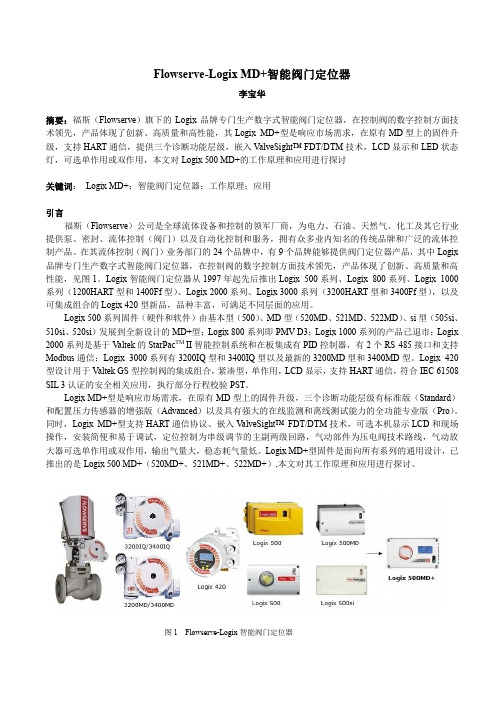
在其流体控制(阀门)业务部门的24个品牌中,有9个品牌能够提供阀门定位器产品,其中Logix 品牌专门生产数字式智能阀门定位器,在控制阀的数字控制方面技术领先,产品体现了创新、高质量和高性能,见图1。
Logix智能阀门定位器从1997年起先后推出Logix 500系列、Logix 800系列、Logix 1000系列(1200HART型和1400Ff型)、Logix 2000系列、Logix 3000系列(3200HART型和3400Ff型),以及可集成组合的Logix 420型新品,品种丰富,可满足不同层面的应用。
Logix 500系列固件(硬件和软件)由基本型(500)、MD型(520MD、521MD、522MD)、si型(505si、510si、520si)发展到全新设计的MD+型;Logix 800系列即PMV D3;Logix 1000系列的产品已退市;Logix 2000系列是基于V altek的StarPac TM II智能控制系统和在板集成有PID控制器,有2个RS 485接口和支持Modbus通信;Logix 3000系列有3200IQ型和3400IQ型以及最新的3200MD型和3400MD型。
定位器logix_3200MD(IOM)(Chinese)
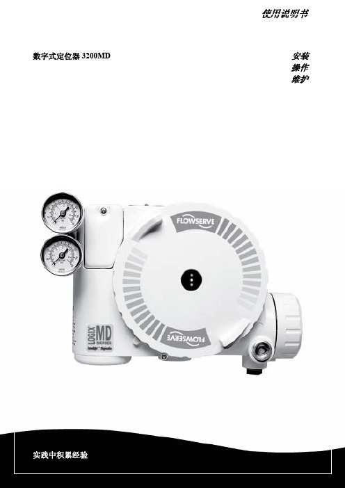
使用说明书数字式定位器3200MD安装操作维护目录1 安全相关术语 32 基本信息 33 拆除包装与储藏 3 3.1 拆除包装 3 3.2 储藏 33.3 安装前的检查 34 Logix 3200MD定位器简介 4 4.1 规格 4 4.2 定位器操作 64.3 详细的定位器操作顺序75 安装8 5.1 安装到Valtek Mark One直通控制阀上8 5.2 安装到标准型Valtek转行程阀上9 5.3 可选的Valtek转行程安装程序 115.4 定位器和执行器的管路连接 116 布线与接地指南 12 6.1 4-20毫安指令输入布线 13 6.2 接地螺钉 13 6.3 顺从电压 13 6.4 电缆要求 136.5 本质安全栅 147 启动调试 14 7.1 Logix 3200MD就地用户面板 14 7.2 初始DIP开关设定操作 14 7.3 DIP开关设定的配置操作 15 7.4 快速校准操作模式下校准Dip开关的设置 16 7.5 快速校准(QUICK-CAL)操作 16 7.6 阀门位置的就地控制 17 7.7 恢复出厂设置 17 7.8 指令重置 17 7.9 版本号检查 17 7.10 Logix 3200MD状态 17 7.11 ValveSight配置、诊断软件和HART375手操器 18 8 维护与维修 21 8.1 驱动器模块组件 21 8.2 调节器 23 8.3 检查或设定内部调节器压力 24 8.4 滑阀 25 8.5 滑阀盖 25 8.6 滑阀阀杆位置传感器 26 8.7 主板PCB组件 27 8.8 压力传感器板 278.9 用户接线板 289 可选硬件 29 9.1 电位器排气口设计 29 9.2 HART调制调解器 309.3 4-20毫安模拟量输出板 3010 零部件列表 3211 Logix 3200MD备件箱 3412 Logix 3200MD安装套件 35 12.1 Valtek安装套件 35 12.2 Logix O.E.M.安装套件 3612.3 NAMUR标准安装套件附件的零件号 3613 常见问题解答 3714 订购详情 3815 故障排除 391 安全相关术语安全术语危险、警告、小心和注意在本说明书中被用来强调特定危险和/或提供与那些很可能出现的危险相关的更多信息。
福斯定位器配置指南
福斯定位器配置指南福斯(FLOWSERVE)阀门定位器调试方法(锦菲特I3599429OO2)[Q-Q,6696 22933]flowserve阀门、Flowserve 3400IQ定位器、LOGIX500、LOGIX510、LOGIX520、D3系列P-5 气动定位器电动气动数字- 通用,IS 和EXHART、Profibus、Foundation 现场总线反馈机组、限位开关比如PP5XX-HPGU-23K01-PV9DA-3ZPMV P-1700 系列阀门专为腐蚀或高温环境应用设计,其所有外部零件均由不锈钢制造而成。
P-1700 和1720 型阀门的内部零件采用不锈钢制造,而P-1710 和P-1730 型阀门的内部零件则采用铝制。
P-1720 和P-1730 型阀门具有超高的空气传送能力。
P-1700 系列阀门专为双向操作应用设计,不过也可通过旋动一个阀座轻松实现单向操作。
不锈钢磁场外壳内的PMV I/P 转换器很容易安装在P-1700 系列阀门上。
P-1500 P-1520P-1700 P-1720P-1710 P-1730Digital具有PID 控制的2000 数字定位器品牌Logix说明福斯Logix 2000 是一款具有板载PID 控制的数字定位器。
通信方式为4-20mA 或Modbus。
阀门上安装的PID 控制器每秒更新阀杆位置16 次,从而减少了控制系统延迟。
Logix3200IQ 数字定位器3200IQ-10-D6-M-04-40-0G-0F3200IQ-10-D6-M-04-40-0G-00品牌Logix说明福斯Logix 3200IQ 数字HART? 定位器使用先进的piezo 技术提供一流的性能和可靠性。
通过使用本地按钮、HART 手持设备和SoftTools软件可轻松配置Logix 3200IQ。
LOGIX 3201IQ定位器P/N:215809.999.000,SN:4107028LOGIX 3202IQ定位器P/N:221734.999.000,SN:4907010LOGIX 3203IQ定位器P/N:216428.999.000,SN:610727定位器P/N:215809.999.000,SN:55070043400IQ Digital Positioner品牌Logix说明The Flowserve Logix 3400 Series digital Foundation? Fieldbuspositioner utilizes state-of-the-art piezo technology to provide…500 数字定位器品牌Logix说明福斯Logix 500 数字定位器是下一代本质安全型Logix 500 系列的代表。
费希尔阀门定位器讲义

费希尔定位器讲义一.费希尔定位器的分类介绍。
二.费希尔定位器的工作原理。
三.费希尔定位器的调试及整定。
四.4200反馈快速调整的方法。
费希尔国际有限公司始于1880年,发明人是william Fisher发明了第一台泵调节器。
分类“DVC5000。
DVC6000。
DVC2000DVC2000----------直行程,角行程。
行程:最大2英寸,在大的行程可以通过增加气动放大器,改变双作用。
没有连接杆和连接件减少了安装零件和安装的复杂程度。
里面带非接触式阀位变送器和阀位开关,阀位变送器需要单独供电。
二. 费希尔定位器的工作原理。
Fisher DVC5000/6000系列智能定位器的结构原理图如下图所示智能定位器结构原理图:工作原理:控制器来的控制信号经端子盒进到印刷线路板子模块,在这里被微处理器读取后经数字算法处理后转换成模拟量后送给I/P转换器。
当信号改变时I/P转换器的线圈和衔铁之间的磁吸引力改变,并因此改变了喷嘴挡板间的距离进而改变了喷嘴背压,该背压经放大器放大后送给执行机构并通过执行机构改变阀杆的位置。
阀行程传感器通过反馈杆感受阀杆位置的变化,并将此信号反给印刷线路板组件参与计算。
当阀杆位置达到正确位置,阀杆位置信号反到印刷线路板组建,经过处理后使I/P驱动信号稳定下来,则喷嘴背压稳定下来,则到执行机构的输出力也稳定下来阀杆位置不再变化。
单作用执行机构:将单作用正作用式数字式阀门控制器(a型气动放大器)连接到单作用执行机构上时,必须把输出口B堵死,把输出口A连接到执行机构膜盖上。
在输出口B处不需要压力表,在其相应位置上改装一个带过滤网的排空管塞。
将单作用反作用式数字式阀门控制器(B型气动放大器)连接到单作用执行机构上时,必须把输出口A堵死,把输出口B连接到执行机构膜盖上。
在输出口A处不需要压力表,应改装一个堵头。
双作用执行机构:当用在双作用执行机构上时,DVC6000系列数字式阀门控制器通常采用A型气动放大器,当无输入信号时,如果气动放大器已经调整好,则输出口A的压力应为0,而输出口B的压力等于输入气源的的压力。
智能阀门定位器 1600 系列用户手册说明书

Intelligent Valve Positioner 1600 Series User’s Manual智能阀门定位器1600系列用户手册Contents1 Overview (1)1.1. Product structure (1)1.2. Product description and application (2)2. Installation (3)2.1. Mechanical dimensions (3)2.2. Actuator combination (5)2.2.1. Actuator of line stroke (5)2.2.2. Actuator of angle stroke (7)2.3. Interface angle adjustment (9)3. Connection description (11)4. Technical data (12)4.1. Working data (12)4.2. Electrical data (12)4.3. Mechanical data (13)4.4. Pneumatic data (13)5. Operation (13)5.1. Interface description (13)5.2. Operating mode and operating interface (14)5.3. Main menu (15)5.3.1. INPUT (16)5.3.2. AUTO TUNE (16)5.3.3. ADD FUNC (18)5.3.3.1. CHARACT (19)5.3.3.2. CUTOFF (22)5.3.3.3. DIR CMD (24)5.3.3.4. LIM STROKE (25)5.3.3.5. DEAD BAND (27)5.3.3.6. SAFEPOS (28)5.3.3.7. BINARY IN(optional) (28)5.3.3.8. OUTPUT(optional) (30)5.3.3.9. SIG ERROR (34)5.3.3.10. CAL USER (35)5.3.3.11. MANU RATE (37)5.3.3.12. CODE (38)5.3.3.13. SET FACT (39)5.3.4. LANGUAGE (39)6. Trouble shooting (40)7. Attention (40)8. Explosion-proof (44)8.1. Standard (44)8.2. Special conditions for Safe use (44)8.3. Product use notes (44)9. Warranty terms (45)10. Technical specifications (46)Intelligent Valve Positioner 1600 Series User’s Manual 1 Overview1.1. Product structureHuman machine interfaceStainless steel body casingMain body casingElectrical connectionPneumatic connectionActuator connectionFigure 1. Positioner structure1.2. Product description and application1600 series intelligent valve positioner is a valve stroke controller based on microprocessor. The valve stroke can be set by external input signal. The positioner can adjust valve stroke quickly and accurately by using automatic control algorithm and PWM control technology,accordingly control the flow of fluid line.The positioner can combine with different pneumatically actuated valves for using. As shown in Figure 2.with diaphragm valve with angle seat valveFigure 2. Combinations of positioner and pneumatically actuated valvesThe product can be used in sealed space and controlled automatically and remotely. It has a variety of auxiliary functions such as transfer characteristic, safety position, cut off, etc. It is easy to install,operate,maintain and has low failure rate.2. Installation2.1. Mechanical dimensionsFigure 3. Mechanical dimensions for line strokeFigure 4. Mechanical dimensions for angle stroke2.2. Actuator combination2.2.1. Actuator of line stroke1. Make sure that the stroke range and the screw thread size of the actuatorwhich needs to combine meet the requirements.2. Separately measure the C1 value when the valve is fully closed and C2value when the valve is fully open by the depth ruler. The values are the distance between the stem top and the datum clamp face of the actuator.As shown in Figure 5.The datum clamp faceof the actuatorValvestrokeValve is fully closed Valve is fully openFigure 5. Actuator measurement3. Adjust the adjusting nut of the displacement sensor. Then measure the Dvalue (as shown in Figure 6) by the depth ruler in the state of the displacement sensor being completely loosened. Calculate the compr- ession value L1 = D –C1, L2 = D –C2. It is recommended that the compression value L1 and L2 are both in the reference range which is showed in Table 1. If L1 value or L2 value is unable to meet the reference range, adjust the D value according to the actual situation.NOTE!The adjusted D value must ensure that L1 >0, L2 <the maximumcompression value of the displacement sensor. Otherwise, the positioner cannot match the actuator.Figure 6. Travel sensor adjustment and measurement4. Raise the internal valve stem of the actuator to the highest position.Makethe actuator connection of the positioner entering into the thread connection of the actuator by NO.32 wrench. As shown in Figure 7.Figure 7. Actuator Combination2.2.2. Actuator of angle stroke1. Fix the mounting body under the positioner. As shown in Figure 8.2. Connect the feedback pole of the positioner with the axis of the actuator.As shown in Figure 8.Figure 8. Graph Installation2.3. Interface angle adjustmentIf you need to adjust the interface angle, relax the hexagon screw in place A (As shown in Figure 10) first. Then adjust the angle clockwise or counter-clockwise in 180°range. After adjusting the angle, lock the angle bythe hexagon screw.Figure 10. Graph operationThe positioner has rotation stopper mechanism. If it is restricted to rotate in one direction, please do not force to rotate continuously. NOTE !180°180°3. Connection descriptionFigure 11. ConnectionNOTE!Error connection of the electrical pin may cause the positioner damage.NOTE!The air source pressure bigger than 7 bar may cause positioner damage.4. Technical data4.1. Working dataAmbient temperature: 0~55 °CProtection class: IP66Vibration resistance parameter: 100Hz4.2. Electrical dataConnections: cable glandSupply voltage:24 V DC ± 10 %, ≥1A. Recommend switching-mode power supply. Power input: <5WInput resistance for set-point signal: 140Ω at 0/4-20mA, 20KΩ at 0-5/10V Input resistance for process signal: 140ΩAnalogue output signal:maximum load 560Ω at 0/4-20mA, maximum current 10mA at 0-5/10VBinary output signal maximum current: 50mABinary input signal: 0-3V = logic ―0‖, 15-30V = logic―1‖4.3. Mechanical dataCover material: Polycarbonate (PC), Stainless steel (304)Sealing material: Silicone rubber (SI)Main body material: Polyamide Resin (PA6-GF30)Control stroke range: 5-50 mm4.4. Pneumatic dataAir pressure range: 3~7 bar, specific values depending on the actuator Connections: Plug-in hose connector G1/4Air quality:ISO 8573-1Solid particle size and density Class 3Dew point Class 3Oil content Class 3Air flow rate:17L/min (input pressure of 0.6Mpa)58L/min (input pressure of 0.6Mpa, only single-acting)5. Operation5.1. Interface descriptionThe positioner includes a 4-key control panel and a 128x64 dot matrix graphics display. User can switch the display and set parameters and functions by pressing the four keys.The functions of the keys are represented in the 4 lower grey bars on the LCD display panel.Figure 12. Operating interface5.2. Operating mode and operating interfaceThe positioner has two operating mode: automatic mode (AUTO) and manual mode (MANU).The positioner default operates in the automatic mode when powering up. At this time, the interface is locked. To unlock the interface, it needs to press both two keys for about 3 seconds.In the automatic mode, the positioner accepts the input signal for set-point value and adjusts the valve stroke automatically.In the manual mode, user mus t press the ―+/-‖ key to adjust the valve stroke manually. The set-point value is the current valve position after adjusting the valve stroke manually or the current valve position after switching from the automatic mode to the manual mode. It is displayed on the manual mode interface.The operating mode can be switched by AUTO key and MANU key if BINARY IN function is not enabled for switching the operating mode. If enabling the BINARY IN function for switching, switching by function keys is not effective. User can switch the operating interface by the function keys. The operating interfaces are descripted in Table 5. The interface will be locked if no keys are pressed for a long time. To unlock the interface, it needs to press both twokeys for about 3 seconds.ValueValue type Key functionsKey 1 Key 2Key 3Key 4Current position in the automatic mode.Press ―POS‖ key or ―AUTO‖ key to display.The value of input signal in the automaticmode. Press ―INPUT‖ key to display.The set-point value in the automatic mode.PressThe temperature value of internal system.Press ―TEMP‖ key to display.Current position value (big font) andposition set-point value (small font) in themanual mode. Press ―MANU‖ key todisplay.Table 5. Operating interface5.3. Main menuUser can operate specific function or set specific parameters under the main menu. The menu interfaces have no lock function. So user should exit to theoperating interface from the main menu after operating specific function or setting specific parameters.Figure 13. Operating structure main menu5.3.1. I NPUTThe option is used to select the type of the input signal for set-point value. Thesignal type is 4-20 mA after factory settings.Figure 14. Operating structure INPUT5.3.2. A UTO TUNEThe function can test the related control parameters including the direction between the aeration state of the actuator and the actual position, the total valve scale, PWM parameters. The whole process will continue for about 2-3minutes if running normally.OPERATING INTERFACEMENUEXITPress for approx.3sAUTO TUNEINPUTADD FUNC LANGUAGEINPUTENTER 4-20 mA 0-20 mA 0-10 V0-5 VSELEXITSystem will check whether the whole valve stroke range is in the effective range of the displacement sensor during the automatic adjustment process. When the whole valve stroke range is out of the effective range of thedisplacement sensor, if the minimum value of the whole valve stroke range is smaller than the minimum value of the effective range of the displacement sensor, LCD displays ―POS MIN ERROR ‖, if the maximum value of the whole valve stroke range is larger than the maximum value of the effective range of the displacement sensor, LCD displays ―POS MAX ERROR ‖. If LCD displays the error information above, it is need to re-match the positioner and the actuator, refer to Chapter 2 for details.Figure 15. Operating structure AUTO TUNEAUTO TUNERUNEXIT TUNE 1 TUNE 2TUNE FINISHPress for approx.3s●Although the positioner has ran the automatic adjustment function in the factory. In order to get the control parameters of the actual work environment, the positioner must run the function again in the actual work environment.●Make sure that the air supply pressure is in the working range of the actuator and has no big wave. Otherwise the automatic adjustment may fail or the test parameters may be error.NOTE !5.3.3. A DD FUNCThe option includes auxiliary functions.Figure 16. operating structure ADD FUNCADD FUNCENTEREXIT CHARACT CUTOFF DIR CMD LIM STROKE DEAD BANDSAFEPOS BINARY IN OUTPUT SIG ERROR CAL USER MANU RATE CODESET FACT5.3.3.1. CHARACTFactory setting:CHARACT option: LINEAR EQ PERC option: 1:25FREE value: 0%, 5%, 10%……95%, 100%The CHARACT function is to determine the relationship between position set-point value and valve stroke. In the actual control system, the controlled variable is usually required to have specific control characteristic, such as linearity. User can select or set the characteristic option to meet the control requirement in the function menu.Set-point value(%)(CMD)Valve stroke(%)(POS)Figure 17. Graph characteristics of linear and equal percentageFigure 18. Operating structure CHARACTCHARACTENTEREXITY100 -> 100.0%Y0 -> 0.0% Y5 -> 5.0%FREEEXITEXITEQ PERC1:33 1:50 25:1 33:1 50:11:25 SELLINEARSELEqual percentage characteristicThe Equal percentage characteristic includes the options of 1:25, 1:33, 1:50, 25:1(inverse), 33:1(inverse), 50:1(inverse). Freely programmable characteristicUser can program free characteristic by operating the FREE option.The position set-point value scale ranging from 0-100 % is divided uniformly into 21 nodes. A freely programmable valve stroke ranging from 0-100 % is assigned to each node.Figure 19. Operating structure CHARACT FREEFREEEXITSELY0 -> 0.0%SET Y0 -> 0.0%OK Y5 -> 5.0%SET Y5 -> 5.0%OKY100 -> 100.0%SET Y100 -> 100.0%OK102030405060708090100102030405060708090100Valve stroke(%)(POS)(CMD)Figure 20. Graph CHARACT FREE5.3.3.2. CUTOFFFactory setting:AUTO CUT MIN value: 1%, AUTO CUT MAX value: 99% MANU CUT MIN value: 2%, MANU CUT MAX value: 98%When the percentage of set-point value is in the enabled range of CUTOFF , the valve is fully deaerated or aerated. The valve is fully close when the percentage of set-point value is less than or equal to MIN setting parameter and is fully open when the percentage of set-point value is greater than or equal to MAX setting parameter.The function divides into AUTO CUT function in the automatic mode and MANU CUT function in the manual mode. Parameter MIN range: 0-25%, Parameter MAX range: 75-100%. When the function is enabled, the sign ―cut off ‖ is indicated on the operating interface.In the automatic mode, when the MIN data is 0%, CUTOFF for closing thevalve is inactive; when the MAX data is 100%, CUTOFF for opening the valve is inactive.When the positioner is running the function, due to the actuator internal characteristics, the valve position will have some deviations after the valve being fully closed or fully opened. As a result, the position value may be smaller than 0% when the valve is fully closed or bigger than 100% when the valve is fully opened.Figure 21. Operating structure CUTOFFCUTOFFENTEREXIT MIN 1%AUTO CUTENTER EXIT MAX 99%MIN 2%MANU CUTENTEREXIT MAX 98%OKSET MIN 1%MIN 1%OKSET MAX 99%MAX 99%102030405060708090100102030405060708090100(CMD)Valve stroke(%)MIN adjustable from 0-25%Figure 22. Graph CUTOFF5.3.3.3. DIR CMDFactory setting:DIR CMD option: RISEThe function is to set the effective sense of direction between the input signal and the position set-point value (CMD).RISE: 0/4 mA or 0 V → 0%, 20 mA or 5/10 V → 100%. FALL: 0/4 mA or 0 V → 100%, 20 mA or 5/10 V →0%.Figure 23. Operating structure DIR CMDInput signalSet-point value(%)(CMD)0/4 mA 0 V20 mA 5/10 VFigure 24. Graph DIR CMD5.3.3.4. LIM STROKEFactory setting:LIM STROKE MIN value: 0% (unlimited) LIM STROKE MAX value: 100% (unlimited)The function limits the automatic adjustment range in the whole valve physical stroke. After setting the limit value, the value of valve stroke (POS) on the display may bigger than 100% or smaller than 0%.MIN adjustment range: 0 – 50 % of the total physical stroke. MAX adjustment range: 50 – 100 % of the total physical stroke.The minimum gap between Min and Max is 50 % of the total physical stroke.DIR CMDENTER RISEFALLEXIT S ELFigure 25. Operating structure LIM STROKE102030405060708090100205070(CMD)Physical stroke(%)(POS)60100160-40Limited stroke(%)(POS)Figure 26. Graph LIM STROKELIM STROKEENTEREXIT OKSET MIN 0%MIN 0%OK SETMAX 100%MAX 100%Please do not set the minimum gap between Min and Max too small inapplication, since it may increase the difficulty of valve stroke adjustment. If to do so for necessary, please change the AUTO DB value bigger.NOTE !5.3.3.5. DEAD BANDFactory setting:AUTO DB value: 1% MANU DB value: 1%The system does not adjust the valve stroke when the gap between the stroke value and the position set-point value is not bigger than the dead band value. The dead band value is divided into automatic dead band value and manual dead band value. The automatic dead band value corresponds to limited scale of the valve stroke. The dead band range is 0.1%-10%.Figure 27. Operating structure DEAD BANDDEAD BANDENTEREXIT OKSET AUTO DB 1%AUTO DB 1%OK SET MANU DB 1%MANU DB 1%The smaller the dead band setting, the higher the control accuracy getting. Please set the dead band value in reason. Because the too small value may cause the solenoid valve in the body to act frequently and lead to long adjustment time and unstable working state. NOTE !5.3.3.6. SAFEPOSFactory setting: SAFEPOS value: 0%The function is used to set a safety position which the valve stroke is adjusted to for some specific conditions. The safety position is adjusted by the binary input signal or an error signal for set-point value. When the adjustment for the safety position is enabled, the sign ―safe pos‖ is indicated on the operating interface.Figure 28. Operating structure SAFEPOS5.3.3.7. BINARY IN(optional)Factory setting:SWITCH option: CLOSEFUNCTION option: SAFEPOS TYPE option: NORMAL OPENThe function is used to operate the positioner to achieve some functions by binary input signal. If the product selection has no feedback signal, this function is invalid.OKSET SAFEPOS 0%SAFEPOSENTEREXIT SAFEPOS 0%Figure 29. Operating structure BINARY INBINARY INENTEREXITENTER SWITCHEXITCLOSEOPENSEL FUNCTIONENTEREXIT SAFEPOSMANU /AUTOSELSEL NORMAL OPENNORMAL CLOSETYPEENTEREXIT5.3.3.8. OUTPUT(optional)Factory setting:ANALOGUE option: POSANALOGUE TYPE option: 4-20 mABINARY option: LIM DEVBINARY VAL DEV value: 10%BINARY VAL POS value: 100%BINARY TYPE option: NORMAL OPENThe function is used to let system output related control parameters or operating states to the other terminals.One analogue output (can be selected according to product type selection): analogue signal of the current position (POS) or of the set-point value (CMD). Two output signal types (4-20mA, 0-20mA) can be selected.Two binary outputs: 0/24V binary signal of operating state related with the system.If the product selection has no feedback signal, this function is invalid.Figure 30. Operating structure OUTPUTFigure 31. Operating structure ANALOGUE TYPEOUTPUTENTEREXIT ANALOGUEENTEREXIT POS CMDSELTYPEBINARYENTEREXIT CHANNEL 1CHANNEL 2TYPEENTER4-20 mA0-20 mASELEXITFigure 32. Operating structure OUTPUT BINARYOKSET VAL DEV 10%VAL DEV 10%SEL NORMAL OPENNORMAL CLOSETYPEENTEREXITENTEREXIT CHANNEL 1CHANNEL 2POS LIM SAFEPOS SP ERRORA/M STATEPOS DEVSELVAL DEV 10%VAL LIM 100%TYPEOKSET VAL LIM 100%VAL LIM 100%5.3.3.9. SIG ERRORFactory setting:SIG ERROR option: ERROR OFFSIG ERROR SAFEPOS option: CLOSEThe function is used to detect the error of 4-20mA input signal, but cannot detect input signal of other types. The error condition is the value of 4-20mA input signal ≤ 3.5mA. If opening the error detecting, the set-point value will instruct ―ERROR‖ on the operating interface in the case of detecting the error signal. If the safety position is not enabled, the single-acting power-off safe positioner will exhaust the actuator cylinder ’s air and the single-acting power-off freeze positioner will keep the valve position and the double-acting positioner will leave the valve position in a free state.Figure 33. Operating structure SIG ERRORSIG ERRORENTEREXIT SAFEPOSENTEREXIT CLOSEOPENSELERROROFF ERROR ONSEL5.3.3.10. CAL USERFactory setting:CAL POS MIN: the AD value of minimum position by AUTO TUNE function. CAL POS MAX: the AD value of maximum position by AUTO TUNE function. CAL INPUT MIN for 4-20mA: 765CAL INPUT MAX for 4-20mA: 3823CAL INPUT MIN for 0-20mA: 0CAL INPUT MAX for 0-20mA: 3823CAL INPUT MIN for 0-10V: 0CAL INPUT MAX for 0-10V: 3413CAL INPUT MIN for 0-5V: 0CAL INPUT MAX for 0-5V: 1707The function is used to calibrate the scale value for valve stroke and input signal. And it is not recommended to be used for general users.The value of calibration is a 12bit AD sample value in the system, the range is 0-4095.CAL FACTRUNCalibration values reset to factory settings Press for approx.3sCAL POSENTEREXITOKSETMIN0 MIN 0OKSETMAX 0 MAX 0CAL INPUTENTEREXITOKSET4mA 0 4mA 0OKSET20mA 0 20mA 0CAL USERENTEREXITCAL POS CAL INPUT CAL FACTFigure 34. Operating structure CAL USERWhen the system is running CAL POS or CAL INPUT function, user should watch the lighted changing value whether tends to be stable. The stable value can be judged according to the range of digital number changing less than 5 for a long time. After judging the stable value, press ―OK‖ key on the display to record current changing value as the new calibration value. The recorded value may be different with the changing value which before recording.NOTE!Write down the current changing value before recording. The changing value to be recorded may be different with the value after being recorded. If the deviation of digital number between them is less than 3, the recorded value is available. Otherwise please run the calibration for the related value again.5.3.3.11. MANU RATEFactory setting:GRADE : 2The function is used for setting the rate for adjusting valve stroke in the manual mode.The grade of adjustment rate: 1-5, 1 is the slowest adjustment rate, 5 is the fastest adjustment rate.Figure 35. Operating structure MANU RATE5.3.3.12. CODEFactory setting:Code: 0000Protect options: noneThe CODE function is to prevent some soft functions of the positioner being accessed. If enabling the CODE function, it needs to input the code before opening the protected menu or running the protected functions.Figure 36. Operating structure CODEOK SET GRADE 2 MANU RATECODE ENTEREXIT CODE INPUTOK EXIT MANU /AUTOADD FUNCAUTO TUNEMAIN MENUCODE MODIFY SEL5.3.3.13. SET FACT All setting parameters reset to factory default value except the parameters of AUTO TUNE and CAL USER. To do so, enter the menu of auxiliary functions, then select the SET FACT option and press the ―RUN‖ key for about 3s. Figure 37. Operating structure SET FACT5.3.4. L ANGUAGE The option is used to select the interface language.Figure 38. Operating structure LANGUAGESET FACTRUN Factory resetPress for approx.3sLANGUAGEENTER CHINESE ENGLISH EXIT SEL6. Trouble shooting1. LCD does not light after the positioner powers up.Make sure that the 24V DC power supply is normal.Make sure that the power cables are connected correctly.2. The positioner is unable to locate position. The valve cannot be fullyopened or fully closed for a long time.Make sure that the pressure of air supply meets the requirement.Make sure that the setting value of limit stroke or dead band are not too small.Make sure that the pneumatic connections of the positioner and actuator are not leaking.7. Attention1.The power supply voltage of the positioner is 24V DC ±10%. Please checkthe power supply before connecting the power cable to the electrical terminal. Make sure that the power supply is cut off before connecting the power cable. If the product is damaged by high voltage, it will lose warranty.2. Air supply use specification1>The air pressure should be less than 0.7MPa.2>Install the filter pressure reducer (5 um filtration accuracy) in front ofthe air supply inlet of the positioner to prevent moisture or oil frominfiltrating. In the situation of much oil in the air, it is suggested toadditionally install oil separator (3 um filtration accuracy) in front of theair supply inlet of the positioner. It is suggested to use the combinationof SMC brand filter pressure reducer and SMC brand oil separator. Itsmodel is AC20D-01CG-A. If the product is damaged due to the oilentering the product without oil separator or filter pressure reducerbeing installed, it will lose warranty.3. Waterproof electrical connectors use specification1> The electrical connectors have foolproof design. Please connect theelectrical female connector with the electrical male connector of thepositioner according to the sign X1 and sign X3. Error connecting bystrong force will destroy the electrical male connector.2> The cable diameter which is compatible with the waterproof electricalconnectors is PG7 (4mm-6mm). Please use the multi - core cable with external insulation protection skin, otherwise the electrical connectors cannot achieve IP66 protection class.Correct and error wiring ways are showing in the following pictures.3> If the electrical male connectors are not used for a long time, toprevent water vapor or corrosive gases corroding the connector pins or entering the positioner inside, please screw on the electrical female connectors and block another side of the electrical female connectors with the silicone plugs. As shown below.If the product is damaged by error operations for the waterproof electrical connectors, it will lose warranty.4. If the product is damaged by the user removing the pneumatic connectorsor the filter elements near the pneumatic connectors, it will lose warranty.5. For matching the angle stroke actuator, make sure that the groove of theactuator axis is vertical, so that the connection between the actuator axis and the positioner sensor is suitable. Otherwise the radial load force will destroy the sensor. If the product is damaged by the above reason, it will lose warranty.8. Explosion-proof8.1. StandardGB3836.1 –2010 Explosive atmospheres —Part 1: Equipment —General requirements.GB3836.8 – 2014 Explosive atmospheres — Part 8: Equipment protection by type of protection ―n‖.Explosion-proof mark: Ex nAⅡC T4 Gc.Explosion-proof certification number: GYB16.1644X.8.2. Special conditions for Safe use1. To prevent the danger of ignition due to static electricity, it is forbidden torub the non-metallic part of the product case.2. After installation of the product, it must be ensured that the overall caseprotection level is not lower than IP54 specified in the GB4208-2008 standard.3. It is forbidden to insert or pull out the external connector of the productduring power-on.4. When using in the field, transient protection measures should be taken toprevent the rated voltage from exceeding 40% due to transient interference.8.3. Product use notes1. When using and maintaining on site, the principle of ―do not open the coverof the product in the explosive atmospheres‖ must be followed.2. Product rated parameter: 24V DC.3. Users are not allowed to replace parts of the product. To prevent theoccurrence of damage, users should work with product manufacturer to solve the problems that occur in operation.4. The installation, use and maintenance of the product should comply withthe requirements of the product user’s manual and the following related standards and specifications.GB3836.13 – 2013 Explosive atmospheres — Part 13: Equipment repair, overhaul and reclamation.GB3836.15 – 2000 Electrical apparatus for explosive gas atmospheres —Part 15: Electrical installations in hazardous areas (other than mines).GB3836.16 – 2006 Electrical apparatus for explosive gas atmospheres —Part 16: Inspection and maintenance of electrical installation (other than mines).GB50257 –2014 Code for construction and acceptance of electric equipment on fire and explosion hazard electrical equipment installation engineering.9. Warranty terms1. If the product is found to have quality problems which are confirmed byour company staff, customers have after-sale services for product maintenance or free replacement in the warranty period.Service response time is 24 hours (excluding non-working days).2. The warranty period of the product is based on the company’s latestwarranty policy, which is no less than 12 months after the sale.3. The following situations for repaired product do not belong to the warrantyrange:(1) The date is not in the warranty period.(2) The product is disassembled without authorization and permit by theproduct company.(3) The damage causes from the operation which is not according to theproduct instruction manual or other human factors. Including but notlimited to:1> The product surface has collision scars.2> Error wiring or error power supply makes the product damaged.3> Parts and accessories are lost.4> The product is damaged due to the oil entering the product withoutoil separator or filter pressure reducer being installed.5> Error using the waterproof electrical connectors makes the productdamaged.(4) Force majeure (natural disasters) causes product failure or damage.4. According to the actual situation, the product company offers the free orfee-based maintenance services outside the warranty range.5. The terms become effective since the two sides signed a supply contract.。
FLOWSERVIER

FLOWSERVE PNEUMATIC REGULATING V ALVESETUP:设定DIP开关得到操作运行方式.压下“QUICK-CAL”按钮并且保持3~4秒,直到灯光顺序地变为黄色灯,等待自动校准过程,(指示灯顺序地变为绿灯).如果自动调整被选择,远程位置调节器增益会被自动地设定,并且能被变化设定增益选择器进行修正.Air action (气动作用) ATO(气动开) ATC(气动关);Signal at closed (信号在关位) 4ma 20ma;Pos. characterization位置特性Linear线性Optional (选择随机); Optional Pos. char(可选择位置特性) =%相等Optional custom(定制); Auto tune(自动调整) ON OFFSpare(备用) A BValve stability(阀门稳定性) Lo friction 低摩擦Hi friction高摩擦Quick calibration(快速校准) Aoto 自动Jog(缓慢给进)FLOWSERVE阀门定位器LOGIX 3200 IQ系列状态代码-详见IOM说明:GGGG 正常运行-模拟量控制模式YRRY 输出量程的100% GGGY 锁紧关断作用击活YRRR 反馈满度太小GGYG 开关量控制模式RGYY 正在读取压力GGYG 初始化状态RGYR 失去供给气源压力GGRG 循环周期越限(用户设定) RGRR 位置偏差报警(拥护设定) GGRY 行程越限(用户设定) RYYY 继电器未动作报警GYYR 到达低软件停止位置(用户设定) RYYR 继电器低位置报警(引导) GYRY 到达高软件停止位置(用户设定) RYRY 继电器高位置报警GRYR 低位报警(用户设定) RRGG 内部参照电压错误GRRY 高位报警(用户设定) RRYG 内部温度报警YGYG 信号试验过程RRYY 传感器电压错误YGRR 就地控制模式RRYR 内部电流回路错误YYGR 压力校准过程RRRY NV 存储器校验求和错误YYYG 回路校准过程YYYY 就地用户接口丧失YRGG 行程校准过程YRGR 校准时反馈不稳定YRYG 校准时设定IL偏移YRYY 校准时没有反馈动作YRYR 反馈输出量程的0%YRRG 等待调节到满量程位置4.3 定位器操作详细说明:很详细的例子解释控制功能,假设单元控制组态如下:﹡单元为模拟量指令信号源﹡定制特性被取消(当然此单元特性是线形的)﹡没有软件限制,没有MPC设定﹡阀门有零点偏差当前输入12mA的信号﹡回路校准为4mA=0%,20mA对应100%指令;﹡执行器已经连管并且定位器组态形式为气开式.给出这些条件,12mA对应阀门的50%,控制指令是1:1的变化.因为有零点偏差存在,阀杆位置也同样在50%,阀杆在要求的位置,执行器的线轴阀在中间位置以平衡上部和下部活塞的压力,这通常称为平衡或空线轴位置.。
- 1、下载文档前请自行甄别文档内容的完整性,平台不提供额外的编辑、内容补充、找答案等附加服务。
- 2、"仅部分预览"的文档,不可在线预览部分如存在完整性等问题,可反馈申请退款(可完整预览的文档不适用该条件!)。
- 3、如文档侵犯您的权益,请联系客服反馈,我们会尽快为您处理(人工客服工作时间:9:00-18:30)。
三、定位器DIP开关的设置 定位器运行之前,首先设置DIP开关。在传统的的非智 能定位器中,几乎所有的配置,都是通过机械机构实现
的。如果改变设置,只能改变机械结构,所以必须重新
拆装定位器的部件。而智能定位器就升级为电子开关实 现。这极大地方便了定位器的配置和调试。
下面就每一个DIP开关的设置进行了说明 1.作用方式
1.2 因调节阀规格、填料的摩擦情况各异,调节阀 硬件组合难以实现最佳控制状态;
1.3 信号的流向是控制仪表单向流入定位器的,当 出现故障时,不能自诊断故障位置或原因;
1.4 喷嘴孔易被灰尘堵塞气源,使定位器不能正常 工作;
1.5 喷嘴需连续供给压缩空气,能耗较大; 1.6 行程和零点调整,需反复调整,调校麻烦; 1.7 功能单一,可扩充性差。
五、就地手动操作 QUICK-CAL按钮和↑和↓三个按钮同时按住三妙钟, 二极管的状态黄-绿-红-红,此时松开三个按钮, 就可以用↑和↓进行阀门开关操作。按QUICK-CAL按 钮即可退出手动操作,恢复自动状态。
六、阀门定位器状态灯提示
GGGG Normal operation-analog command mode 正常模 拟信号输入运行
3.阀位与信号对应曲线 线性曲线(Linear) 关系
选择曲线(Optional) 活了下一个DIP开关
阀门位置与信号成线性 选择了这个按钮,就激
4.可选择曲线
%=
阀位与信号成等百分比
Custom
用户自定义曲线
5.自动校准
on 每次按动QUICK-CAL按钮,定位器就自动调 整参数进行调试 off 每次调试时,只能根据出厂前的预设置即调节 定位器增益的旋转开关的位置进行调试 无论哪一种情况,调节定位器增益的旋转开关都可 以进行调节,调节完毕,不用重新进行调试,是即 时生效的。
GGGY Tight shutoff(MPC) active 紧密关闭有效 GGYG Digital command mode 数字命令模式 GGYR Initializing 正在初始化 GGRG Cycle limit exceeded (user set) 超出循环极限 (用 户设定)
GGRY Travel limit ext stop reached (user set) 设定低位达到值
GYRY Upper soft stop reached (user set) 设定高位达到 值
GYRR Squawk mode (user set ) 故障模式(发送信号模 式)
GRGR Piezo control voltage low 压力控制电压低 GRYR Lower position alert (user set) 低位警报 GRRY Upper position alert (user set) 高位警报 YGYG signature test in progerss 信号测试进行中 YGRR local jog command mode 本地微调命令模式 YYGR perssure calibration in progress 压力整定进行中
Flowserve阀门定位器
智能阀门定位器: 智能阀门定位器(IntelligentValvePositioner)是以
微处理器技术为基础,采用数字化技术进行数据处理、决策生成 和双向通信的智能过程控制仪表。智能阀门定位器按供电方式可 分为单独供电和不用单独供电;按隔爆级别可分为隔爆和不隔爆 。
1.传统非智能阀门定位器存在问题 1.1 采用采用喷嘴挡板技术即机械力平衡工作原理 ,可动部件较多,易受温度、振动影响;
2. 智能阀门定位器优点 2.1 定位精度和可靠性高。机械可动部件少,输入 信号和阀位反馈信号直接进行数字比较,不易受 环境影响,稳定性好,不存在机械误差造成的死 区影响,具有更高的定位精度和可靠性; 2.2 流量特性修改方便。智能阀门定位包括直线、 等百分比、快开特性功能模块,可以通过按钮或 上位机、手持式设定器进行数据设定; 2.3 零点、量程调整简单。零点调整与量程调整互 不干涉,调整过程简单快捷; 的组态、调试和诊断。
2.4 具有诊断和检测功能。接收数字信号的智能阀门 定位器,具有双向的通讯能力,可以就地或远距离 地利用上位机或手持式操作器进行阀门定位器的组 态、调试和诊断。
一、简介 Logix3200IQ智能定位器接受4-20mA模拟量 输入,4-20mA模拟量输出。
二、定位器操作面板介绍 Logix3200IQ智能定位器就地操作面板由能够 自动调校零点和满量程的QUICK-CAL快速调 校按钮与可以手动操作定位器的两个点动按 钮(↑和↓)以及八个DIP开关和可以调节定位 器增益的旋转开关组成。
6.稳定性开关 Low-Friction Valves 适用低摩擦力调节阀 High-Friction Valves 适用高摩擦力调节阀
7.备用开关
8.定位器调试方式 Auto 定位器自动调试 Jog 手动调试,用户可以根据需要手动确定阀门 的100%的位置
四、手动点动调试
首先将调校DIP开关拨到Jog位置,用户只能手动设置 满量程,不能设置全关位,阀门全关位为默认状态。当 DIP 开关拨到Jog位置时,定位器的二极管的状态为黄- 红-红-绿。此时用户再用Jog按钮↑↓手动调节阀门 至所期望的100%,阀门到位后,同时按↑和↓按钮,这 时阀门自动进行调整,等调整结束后二极管的状态回到 黄-红-红-绿,再重新进行100%的设定,设定完成 后,同时按↑和↓按钮,阀门进行自动调整。调整完毕 后,二极管的状态以绿色开始。这表明手动调试完成, 定位器正常。
作用方式分气开式(ATO)和气关式(ATC)两种,调试前根据 阀门的类型进行设置。
气开还是气关主要是从安全角度出发,即要考虑在控制阀上的信 号一旦中断后,阀所处的位置是全开还是全关对装置安全更有利 ?如果是全开更有利则选用气关,这样一旦失去信号控制阀就处 于全开位置。反之,则选用气开阀。
2. 阀门的控制信号(正作用和反作用) 正作用: 信号4mA时阀门处于全关位置, 信号20mA时阀门处于全开位置 反作用:信号20mA时阀门处于全关位置, 信号4mA时阀门处于全开位置
