MC33067PG中文资料
MC33064中文资料
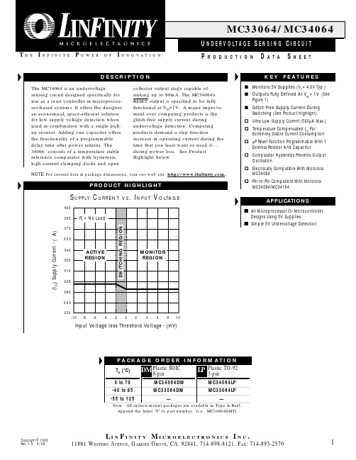
(ICC) Supply Current - ( A)
ACTIVE REGION
MONITOR REGION
-8
-6
-4
-2
0
2
4
6
8
10
Input Voltage less Threshold Voltage - (mV)
PA C K A G E O R D E R I N F O R M A T I O N TA (°C) 0 to 70 -40 to 85 -55 to 125
NOTE: For current data & package dimensions, visit our web site: .
PRODUCT HIGHLIGHT
S U P P LY C U R R E N T
400 385 370 355 340 325 310 295 280 265 250 -10
N.C. N.C. N.C. N.C.
DM PACKAGE (Top View)
3. GROUND 2. VIN 1. RESET
THERMAL DATA
DM PACKAGE: THERMAL RESISTANCE-JUNCTION TO AMBIENT, θJA LP PACKAGE: THERMAL RESISTANCE-JUNCTION TO AMBIENT, θJA 156°C/W 165°C/W LP PACKAGE (Top View)
MC34167MC33167中文资料
MC34167 MC331671简介该MC34167, MC33167系列单片电源开关可用于dc–to–dc优化调节器申请.这些器件的固定频率,电压模式稳压器包含了所有的积极作用需要直接和实施step–down以最小的转换数量voltage–inverting外部元件.它们也可以用于成本效益在step–up转换器应用.潜在市场包括汽车,计算机,工业和成本敏感的消费产品.每一个设备的部分介绍给下面与代表框图所示图13.2振荡器振荡器频率内部编程72 kHz的电容CT和修剪电流源.该充放电率控制在产生一个95%在开关输出的最大占空比.在CT的放电,振荡器产生内部消隐脉冲持有的反相输入与门高,禁用输出开关晶体管.标称振荡器峰值和山谷门槛4.1 V和2.3 V分别.3脉宽调制器脉宽调制器由一个比较器振荡器斜坡电压施加到非反相输入端,而误差放大器的输出应用到反相输入.输出开关导通时启动CT检查排放到振荡器峰谷电压.至于收费的CT电压超过误差放大器的输出,锁存复位,终止输出晶体管的导通时间振荡器的ramp–up时期.这PWM /锁存结合防止在给定的多输出脉冲振荡器时钟周期.数字6和14说明开关输出电压与占空比的补偿.4电流检测该系列采用MC34167当前cycle–by–cycle限制,作为保护手段输出开关晶体管从过度紧张.在每个周期视为一个单独的情况.电流限制是通过监测输出开关晶体管的电流传导期间建设,并经检测过流情况,请立即关闭为振荡器的ramp–up期内开关.集电极电流转换为电压由内部微调电阻和对一个参考比较由电流检测比较器.当电流限制达到阈值,比较器重置PWM 锁存.限流门限点往往设在6.5 A.图9说明开关与输出电流限制门槛温度.5误差放大器和参考一个误差放大器的高增益提供了访问反相输入和输出.该放大器具有典型dc电压增益80 dB,和单位增益带宽600 kHz与相边缘 70度(图3).同相输入偏置内部5.05 V参考并且不固定了.参考具有精度±2.0%在室温下.以提供负载5.0 V中,参考编程50以上mV 5.0 V补偿在电缆的电压降和1.0%从连接器转换器输出.如果转换器设计需要一个输出电压高于5.05 V,电阻更大R1必须加入形成一个分压网络的反馈输入中所示数字13和18.了确定输出方程与分压网络的电压为:Vout+5.05R2R1)1外部回路补偿所需的转换器稳定.一个简单的low–pass滤波器是由连接电阻(R2)从稳压输出到反相输入,以及一系列resistor–capacitor (RF, CF)之间Pins 1和5.补偿网络的元件值显示在电路的申请被选定为each在稳定工作条件下进行测试.该step–down转换器(图18)是最容易补偿稳定.该step–up(图20)和voltage–inverting(图22)配置运作,连续导反激式转换器,而且更难以弥补.该最简单的方法来优化网络是补偿观察输出电压的负载响应一步变化,而调整临界阻尼RF和CF.该最终电路应验证以下四个稳定边界条件.这些条件是最小和最大输入电压,最小和最大负载.通过箝位的电压误差放大器的输出(引脚5)不到150 mV,内部电路将放置到一个低功耗待机模式,从而将权力电源电流36µA与12 V电源电压.图10说明了备用电源电流与电源电压.误差放大器的输出有一个100µA电流源pull–up,可用于实现soft–start.图17显示充电电流源通过一个电容CSS系列二极管.该二极管断开从反馈CSS回路电阻时1.0 M操作它上面的收费销5.范围开关输出输出开关晶体管的设计最大的40 V,以最小的峰值集电极电流时5.5 A.配置为step–down或voltage–inverting应用,如在图18和22,电感会把偏置的输出整流开关关闭时.整流器与较高的正向电压降或长期拖延的时间应该打开不能使用.如果发射器被允许去充分负,集电极电流流过,造成额外的装置暖气,降低转换效率.图8显示到箝位的发射器0.5集电极电流V,在一系列的100µA温度过高.阿1N5825或肖特基势垒整流器相当于推荐履行这些要求.欠压分离欠压分离一直比较成立以保证完全集成电路在输出级的功能已启用.内部参考电压比较器的监测使输出阶段VCC超过5.9 V.为了防止不稳定的输出交叉切换的阈值,0.9 V迟滞.6摩托罗拉设备数据模拟ICMC34167 MC33167热保护内部热关断电路,以保护在事件集成电路的最大结温度超过.当被激活时,通常在170°C,是被迫的锁存成'复位'的状态,关闭输出开关.此功能防止灾难性故障提供偶然的设备过热.它的目的不是要作为一个适当的散热片的替代品.该MC34167包含在5–lead TO–220类型包装.该标签包装是很常见的中心引脚(引脚3),通常连接到地.设计考虑不要试图建立一个转换器上wire–wrap或plug–in原型板.特别应注意分开的信号电流和接地接地通路从负载电流路径.所有高电流回路应尽可能短尽可能使用重型铜runs到尽量减少振荡和辐射EMI.为了获得最佳的操作,严密元件布局建议.电容器Cin, CO,和所有的反馈元件应尽可能靠近IC在身体可能.这也是必须的肖特基二极管连接到开关输出是尽可能靠近尽可能IC.图15.低功耗待机电路+100µA错误放大器1图16.过电压关断电路+100µA错误放大器1120补偿5120补偿R15R1I =待机模式VShutdown = VZener + 0.7图17. Soft–Start电路+100µA错误放大器1120补偿D2Vin1.0 MCss5D1R1tSoft–Start≈35,000 Css。
3037a中文资料

3037a中文资料篇一:常用电源转换芯片常用电源转换芯片第1章DC-DC电源转换器/基准电压源1.1DC-DC电源转换器1.低噪声电荷泵DC-DC电源转换器AAT3113/AAT31142.低功耗开关型DC-DC电源转换器ADP30003.高效3A开关稳压器AP15014.高效率无电感DC-DC电源转换器FAN56605.小功率极性反转电源转换器ICL76606.高效率DC-DC电源转换控制器IRU30377.高性能降压式DC-DC电源转换器ISL64208.单片降压式开关稳压器L49609.大功率开关稳压器L4970A10.1.5A降压式开关稳压器L497111.2A高效率单片开关稳压器L497812.1A高效率升压/降压式DC-DC电源转换器L597013.1.5A降压式DC-DC电源转换器LM157214.高效率1A降压单片开关稳压器LM1575/LM2575/LM2575HV15.3A降压单片开关稳压器LM2576/LM2576HV16.可调升压开关稳压器LM257717.3A降压开关稳压器LM259618.高效率5A开关稳压器LM267819.升压式DC-DC电源转换器LM2703/LM270420.电流模式升压式电源转换器LM273321.低噪声升压式电源转换器LM275022.小型75V降压式稳压器LM500723.低功耗升/降压式DC-DC电源转换器LT107324.升压式DC-DC电源转换器LT161525.隔离式开关稳压器LT172526.低功耗升压电荷泵LT175127.大电流高频降压式DC-DC电源转换器LT176528.大电流升压转换器LT193529.高效升压式电荷泵LT193730.高压输入降压式电源转换器LT195631.1.5A升压式电源转换器LT196132.高压升/降压式电源转换器LT343333.单片3A升压式DC-DC电源转换器LT343634.通用升压式DC-DC电源转换器LT346035.高效率低功耗升压式电源转换器LT346436.1.1A升压式DC-DC电源转换器LT346737.大电流高效率升压式DC-DC电源转换器LT378238.微型低功耗电源转换器LTC175439.1.5A单片同步降压式稳压器LTC187540.低噪声高效率降压式电荷泵LTC191141.低噪声电荷泵LTC3200/LTC3200-542.无电感的降压式DC-DC电源转换器LTC325143.双输出/低噪声/降压式电荷泵LTC325244.同步整流/升压式DC-DC电源转换器LTC340145.低功耗同步整流升压式DC-DC电源转换器LTC340247.双路同步降压式DC-DC电源转换器LTC340748.高效率同步降压式DC-DC电源转换器LTC341649.微型2A升压式DC-DC电源转换器LTC342650.2A两相电流升压式DC-DC电源转换器LTC342851.单电感升/降压式DC-DC电源转换器LTC344052.大电流升/降压式DC-DC电源转换器LTC344253.1.4A同步升压式DC-DC电源转换器LTC345854.直流同步降压式DC-DC电源转换器LTC370355.双输出降压式同步DC-DC电源转换控制器LTC373656.降压式同步DC-DC电源转换控制器LTC377057.双2相DC-DC电源同步控制器LTC380258.高性能升压式DC-DC电源转换器MA某1513/MA某151459.精简型升压式DC-DC电源转换器MA某1522/MA某1523/MA某152460.高效率40V升压式DC-DC电源转换器MA某1553/MA某155461.高效率升压式LED电压调节器MA某1561/MA某159962.高效率5路输出DC-DC电源转换器MA某156563.双输出升压式DC-DC电源转换器MA某1582/MA某1582Y64.驱动白光LED的升压式DC-DC电源转换器MA某158365.高效率升压式DC-DC电源转换器MA某1642/MA某164366.2A降压式开关稳压器MA某164467.高效率升压式DC-DC电源转换器MA某1674/MA某1675/MA某167668.高效率双输出DC-DC电源转换器MA某167769.低噪声1A降压式DC-DC电源转换器MA某1684/MA某168570.高效率升压式DC-DC电源转换器MA某169871.高效率双输出降压式DC-DC电源转换器MA某171572.小体积升压式DC-DC电源转换器MA某1722/MA某1723/MA某172473.输出电流为50mA的降压式电荷泵MA某173074.升/降压式电荷泵MA某175975.高效率多路输出DC-DC电源转换器MA某180076.3A同步整流降压式稳压型MA某1830/MA某183177.双输出开关式LCD电源控制器MA某187878.电流模式升压式DC-DC电源转换器MA某189679.具有复位功能的升压式DC-DC电源转换器MA某194780.高效率PWM降压式稳压器MA某1992/MA某199381.大电流输出升压式DC-DC电源转换器MA某61882.低功耗升压或降压式DC-DC电源转换器MA某62983.PWM升压式DC-DC电源转换器MA某668/MA某66984.大电流PWM降压式开关稳压器MA某724/MA某72685.高效率升压式DC-DC电源转换器MA某756/MA某75786.高效率大电流DC-DC电源转换器MA某761/MA某76287.隔离式DC-DC电源转换器MA某8515/MA某8515A88.高性能24V升压式DC-DC电源转换器MA某872789.升/降压式DC-DC电源转换器MC33063A/MC34063A90.5A升压/降压/反向DC-DC电源转换器MC33167/MC3416791.低噪声无电感电荷泵MCP1252/MCP125392.高频脉宽调制降压稳压器MIC220393.大功率DC-DC升压电源转换器MIC229594.单片微型高压开关稳压器NCP1030/NCP103195.低功耗升压式DC-DC电源转换器NCP1400A96.高压DC-DC电源转换器NCP140397.单片微功率高频升压式DC-DC电源转换器NCP141098.同步整流PFM步进式DC-DC电源转换器NCP142199.高效率大电流开关电压调整器NCP1442/NCP1443/NCP1444/NCP1445100.新型双模式开关稳压器NCP1501101.高效率大电流输出DC-DC电源转换器NCP1550102.同步降压式DC-DC电源转换器NCP1570103.高效率升压式DC-DC电源转换器NCP5008/NCP5009104.大电流高速稳压器RT9173/RT9173A105.高效率升压式DC-DC电源转换器RT9262/RT9262A106.升压式DC-DC电源转换器SP6644/SP6645107.低功耗升压式DC-DC电源转换器SP6691108.新型高效率DC-DC电源转换器TPS54350109.无电感降压式电荷泵TPS6050某110.高效率升压式电源转换器TPS6101某111.28V恒流白色LED驱动器TPS61042112.具有LDO输出的升压式DC-DC电源转换器TPS6112某113.低噪声同步降压式DC-DC电源转换器TPS6200某114.三路高效率大功率DC-DC电源转换器TPS75003115.高效率DC-DC电源转换器UCC39421/UCC39422116.PWM控制升压式DC-DC电源转换器某C6371117.白光LED驱动专用DC-DC电源转换器某C9116118.500mA同步整流降压式DC-DC电源转换器某C9215/某C9216/某C9217119.稳压输出电荷泵某C9801/某C9802120.高效率升压式电源转换器Z某LB16001.2线性/低压差稳压器121.具有可关断功能的多端稳压器BA某某某122.高压线性稳压器HIP5600123.多路输出稳压器KA7630/KA7631124.三端低压差稳压器LM2937125.可调输出低压差稳压器LM2991126.三端可调稳压器LM117/LM317127.低压降CMOS500mA线性稳压器LP38691/LP38693128.输入电压从12V到450V的可调线性稳压器LR8129.300mA非常低压降稳压器(VLDO)LTC3025130.大电流低压差线性稳压器L某8610131.200mA负输出低压差线性稳压器MA某1735132.150mA低压差线性稳压器MA某8875133.带开关控制的低压差稳压器MC33375134.带有线性调节器的稳压器MC33998136.低静态电流低压差稳压器NCP562/NCP563137.具有使能控制功能的多端稳压器PQ某某138.五端可调稳压器SI-3025B/SI-3157B140.五端线性稳压器STR20某某141.五端线性稳压器STR90某某142.具有复位信号输出的双路输出稳压器TDA8133143.具有复位信号输出的双路输出稳压器TDA8138/TDA8138A 144.带线性稳压器的升压式电源转换器TPS6110某145.低功耗50mA低压降线性稳压器TPS760某某146.高输入电压低压差线性稳压器某C6202147.高速低压差线性稳压器某C6204148.高速低压差线性稳压器某C6209F149.双路高速低压差线性稳压器某C64011.3基准电压源150.新型某FET基准电压源ADR290/ADR291/ADR292/ADR293151.低功耗低压差大输出电流基准电压源MA某610某152.低功耗1.2V基准电压源MA某6120153.2.5V精密基准电压源MC1403154.2.5V/4.096V基准电压源MCP1525/MCP1541155.低功耗精密低压降基准电压源REF30某某/REF31某某156.精密基准电压源TL431/KA431/TLV431A第2章AC-DC转换器及控制器1.厚膜开关电源控制器DP104C2.厚膜开关电源控制器DP308P3.DPA-Switch系列高电压功率转换控制器DPA423/DPA424/DPA425/DPA4264.电流型开关电源控制器FA13842/FA13843/FA13844/FA138455.开关电源控制器FA5310/FA53116.PWM开关电源控制器FAN75567.绿色环保的PWM开关电源控制器FAN76018.FPS型开关电源控制器FS6M07652R9.开关电源功率转换器FS6S某某10.降压型单片AC-DC转换器HV-2405E11.新型反激准谐振变换控制器ICE1QS0112.PWM电源功率转换器KA1M088013.开关电源功率转换器KA2S0680/KA2S088014.电流型开关电源控制器KA38某某15.FPS型开关电源功率转换器KA5H0165R16.FPS型开关电源功率转换器KA5Q某某17.FPS型开关电源功率转换器KA5S某某18.电流型高速PWM控制器L499019.具有待机功能的PWM初级控制器L599120.低功耗离线式开关电源控制器L659021.LINKSWITCHTN系列电源功率转换器LNK304/LNK305/LNK30622.LINKSWITCH系列电源功率转换器LNK500/LNK501/LNK52023.离线式开关电源控制器M51995A24.PWM电源控制器M62281P/M62281FP25.高频率电流模式PWM控制器MA某5021/MA某502226.新型PWM开关电源控制器MC4460427.电流模式开关电源控制器MC4460528.低功耗开关电源控制器MC4460829.具有PFC功能的PWM电源控制器ML482430.液晶显示器背光灯电源控制器ML487631.离线式电流模式控制器NCP120032.电流模式脉宽调制控制器NCP120533.准谐振式PWM控制器NCP120734.低成本离线式开关电源控制电路NCP121535.低待机能耗开关电源PWM控制器NCP123036.STR系列自动电压切换控制开关STR8某某某某37.大功率厚膜开关电源功率转换器STR-F665438.大功率厚膜开关电源功率转换器STR-G865639.开关电源功率转换器STR-M6511/STR-M652940.离线式开关电源功率转换器STR-S5703/STR-S5707/STR-S570841.离线式开关电源功率转换器STR-S6401/STR-S6401F/STR-S6411/STR-S6411F42.开关电源功率转换器STR-S651343.离线式开关电源功率转换器TC33369~TC3337444.高性能PFC与PWM组合控制集成电路TDA16846/TDA1684745.新型开关电源控制器TDA1685046.“绿色”电源控制器TEA150447.第二代“绿色”电源控制器TEA150748.新型低功耗“绿色”电源控制器TEA153349.开关电源控制器TL494/KA7500/MB375950.TinySwitchⅠ系列功率转换器TNY253、TNY254、TNY25551.TinySwitchⅡ系列功率转换器TNY264P~TNY268G4第1章DC-DC电源转换器/基准电压源1.1DC-DC电源转换器1.低噪声电荷泵DC-DC电源转换器AAT3113/AAT31142.低功耗开关型DC-DC电源转换器ADP30003.高效3A开关稳压器AP15014.高效率无电感DC-DC电源转换器FAN56605.小功率极性反转电源转换器ICL76606.高效率DC-DC电源转换控制器IRU30377.高性能降压式DC-DC电源转换器ISL64208.单片降压式开关稳压器L49609.大功率开关稳压器L4970A10.1.5A降压式开关稳压器L497111.2A高效率单片开关稳压器L497812.1A高效率升压/降压式DC-DC电源转换器L597013.1.5A降压式DC-DC电源转换器LM157214.高效率1A降压单片开关稳压器LM1575/LM2575/LM2575HV15.3A降压单片开关稳压器LM2576/LM2576HV16.可调升压开关稳压器LM257717.3A降压开关稳压器LM259618.高效率5A开关稳压器LM267819.升压式DC-DC电源转换器LM2703/LM270420.电流模式升压式电源转换器LM273321.低噪声升压式电源转换器LM275022.小型75V降压式稳压器LM500723.低功耗升/降压式DC-DC电源转换器LT107324.升压式DC-DC电源转换器LT161525.隔离式开关稳压器LT172526.低功耗升压电荷泵LT175127.大电流高频降压式DC-DC电源转换器LT176528.大电流升压转换器LT193529.高效升压式电荷泵LT193730.高压输入降压式电源转换器LT195631.1.5A升压式电源转换器LT196132.高压升/降压式电源转换器LT343333.单片3A升压式DC-DC电源转换器LT343634.通用升压式DC-DC电源转换器LT346035.高效率低功耗升压式电源转换器LT346436.1.1A升压式DC-DC电源转换器LT346737.大电流高效率升压式DC-DC电源转换器LT378238.微型低功耗电源转换器LTC175439.1.5A单片同步降压式稳压器LTC187540.低噪声高效率降压式电荷泵LTC191141.低噪声电荷泵LTC3200/LTC3200-542.无电感的降压式DC-DC电源转换器LTC325143.双输出/低噪声/降压式电荷泵LTC325244.同步整流/升压式DC-DC电源转换器LTC340145.低功耗同步整流升压式DC-DC电源转换器LTC340246.同步整流降压式DC-DC电源转换器LTC340547.双路同步降压式DC-DC电源转换器LTC340748.高效率同步降压式DC-DC电源转换器LTC341649.微型2A升压式DC-DC电源转换器LTC342650.2A两相电流升压式DC-DC电源转换器LTC342851.单电感升/降压式DC-DC电源转换器LTC344052.大电流升/降压式DC-DC电源转换器LTC344253.1.4A同步升压式DC-DC电源转换器LTC345854.直流同步降压式DC-DC电源转换器LTC370355.双输出降压式同步DC-DC电源转换控制器LTC373656.降压式同步DC-DC电源转换控制器LTC377057.双2相DC-DC电源同步控制器LTC380258.高性能升压式DC-DC电源转换器MA某1513/MA某151459.精简型升压式DC-DC电源转换器MA某1522/MA某1523/MA某152460.高效率40V升压式DC-DC电源转换器MA某1553/MA某155461.高效率升压式LED电压调节器MA某1561/MA某159962.高效率5路输出DC-DC电源转换器MA某156563.双输出升压式DC-DC电源转换器MA某1582/MA某1582Y64.驱动白光LED的升压式DC-DC电源转换器MA某158365.高效率升压式DC-DC电源转换器MA某1642/MA某164366.2A降压式开关稳压器MA某164467.高效率升压式DC-DC电源转换器MA某1674/MA某1675/MA某167668.高效率双输出DC-DC电源转换器MA某167769.低噪声1A降压式DC-DC电源转换器MA某1684/MA某168570.高效率升压式DC-DC电源转换器MA某169871.高效率双输出降压式DC-DC电源转换器MA某171572.小体积升压式DC-DC电源转换器MA某1722/MA某1723/MA某172473.输出电流为50mA的降压式电荷泵MA某173074.升/降压式电荷泵MA某175975.高效率多路输出DC-DC电源转换器MA某180076.3A同步整流降压式稳压型MA某1830/MA某183177.双输出开关式LCD电源控制器MA某187878.电流模式升压式DC-DC电源转换器MA某189679.具有复位功能的升压式DC-DC电源转换器MA某194780.高效率PWM降压式稳压器MA某1992/MA某199381.大电流输出升压式DC-DC电源转换器MA某61882.低功耗升压或降压式DC-DC电源转换器MA某62983.PWM升压式DC-DC电源转换器MA某668/MA某66984.大电流PWM降压式开关稳压器MA某724/MA某72685.高效率升压式DC-DC电源转换器MA某756/MA某75786.高效率大电流DC-DC电源转换器MA某761/MA某76287.隔离式DC-DC电源转换器MA某8515/MA某8515A88.高性能24V升压式DC-DC电源转换器MA某872789.升/降压式DC-DC电源转换器MC33063A/MC34063A90.5A升压/降压/反向DC-DC电源转换器MC33167/MC3416791.低噪声无电感电荷泵MCP1252/MCP125392.高频脉宽调制降压稳压器MIC220393.大功率DC-DC升压电源转换器MIC229594.单片微型高压开关稳压器NCP1030/NCP103195.低功耗升压式DC-DC电源转换器NCP1400A96.高压DC-DC电源转换器NCP140397.单片微功率高频升压式DC-DC电源转换器NCP141098.同步整流PFM步进式DC-DC电源转换器NCP142199.高效率大电流开关电压调器NCP1442/NCP1443/NCP1444/NCP1445100.新型双模式开关稳压器NCP1501101.高效率大电流输出DC-DC电源转换器NCP1550102.同步降压式DC-DC电源转换器NCP1570103.高效率升压式DC-DC电源转换器NCP5008/NCP5009104.大电流高速稳压器RT9173/RT9173A105.高效率升压式DC-DC电源转换器RT9262/RT9262A第1章DC-DC电源转换器/基准电压源1.1DC-DC电源转换器1.低噪声电荷泵DC-DC电源转换器AAT3113/AAT31142.低功耗开关型DC-DC电源转换器ADP30003.高效3A开关稳压器AP15014.高效率无电感DC-DC电源转换器FAN56605.小功率极性反转电源转换器ICL76606.高效率DC-DC电源转换控制器IRU30377.高性能降压式DC-DC电源转换器ISL64208.单片降压式开关稳压器L49609.大功率开关稳压器L4970A10.1.5A降压式开关稳压器L497111.2A高效率单片开关稳压器L497812.1A高效率升压/降压式DC-DC电源转换器L597013.1.5A降压式DC-DC电源转换器LM157214.高效率1A降压单片开关稳压器LM1575/LM2575/LM2575HV15.3A降压单片开关稳压器LM2576/LM2576HV16.可调升压开关稳压器LM257717.3A降压开关稳压器LM259618.高效率5A开关稳压器LM267819.升压式DC-DC电源转换器LM2703/LM270420.电流模式升压式电源转换器LM273321.低噪声升压式电源转换器LM275022.小型75V降压式稳压器LM500723.低功耗升/降压式DC-DC电源转换器LT107324.升压式DC-DC电源转换器LT161525.隔离式开关稳压器LT172526.低功耗升压电荷泵LT175127.大电流高频降压式DC-DC电源转换器LT176528.大电流升压转换器LT193529.高效升压式电荷泵LT193730.高压输入降压式电源转换器LT195631.1.5A升压式电源转换器LT196132.高压升/降压式电源转换器LT343333.单片3A升压式DC-DC电源转换器LT343634.通用升压式DC-DC电源转换器LT346035.高效率低功耗升压式电源转换器LT346436.1.1A升压式DC-DC电源转换器LT346737.大电流高效率升压式DC-DC电源转换器LT378238.微型低功耗电源转换器LTC175439.1.5A单片同步降压式稳压器LTC187540.低噪声高效率降压式电荷泵LTC191141.低噪声电荷泵LTC3200/LTC3200-542.无电感的降压式DC-DC电源转换器LTC325143.双输出/低噪声/降压式电荷泵LTC325244.同步整流/升压式DC-DC电源转换器LTC340145.低功耗同步整流升压式DC-DC电源转换器LTC340246.同步整流降压式DC-DC电源转换器LTC340547.双路同步降压式DC-DC电源转换器LTC340748.高效率同步降压式DC-DC电源转换器LTC341649.微型2A升压式DC-DC电源转换器LTC342650.2A两相电流升压式DC-DC电源转换器LTC342851.单电感升/降压式DC-DC电源转换器LTC344052.大电流升/降压式DC-DC电源转换器LTC344253.1.4A同步升压式DC-DC电源转换器LTC345854.直流同步降压式DC-DC电源转换器LTC370355.双输出降压式同步DC-DC电源转换控制器LTC373656.降压式同步DC-DC电源转换控制器LTC377057.双2相DC-DC电源同步控制器LTC380258.高性能升压式DC-DC电源转换器MA某1513/MA某151459.精简型升压式DC-DC电源转换器MA某1522/MA某1523/MA某152460.高效率40V升压式DC-DC电源转换器MA某1553/MA某155461.高效率升压式LED电压调节器MA某1561/MA某159962.高效率5路输出DC-DC电源转换器MA某156563.双输出升压式DC-DC电源转换器MA某1582/MA某1582Y64.驱动白光LED的升压式DC-DC电源转换器MA某158365.高效率升压式DC-DC电源转换器MA某1642/MA某164366.2A降压式开关稳压器MA某164467.高效率升压式DC-DC电源转换器MA某1674/MA某1675/MA某167668.高效率双输出DC-DC电源转换器MA某167769.低噪声1A降压式DC-DC电源转换器MA某1684/MA某168570.高效率升压式DC-DC电源转换器MA某169871.高效率双输出降压式DC-DC电源转换器MA某171572.小体积升压式DC-DC电源转换器MA某1722/MA某1723/MA某172473.输出电流为50mA的降压式电荷泵MA某173074.升/降压式电荷泵MA某175975.高效率多路输出DC-DC电源转换器MA某180076.3A同步整流降压式稳压型MA某1830/MA某183177.双输出开关式LCD电源控制器MA某187878.电流模式升压式DC-DC电源转换器MA某189679.具有复位功能的升压式DC-DC电源转换器MA某194780.高效率PWM降压式稳压器MA某1992/MA某199381.大电流输出升压式DC-DC电源转换器MA某61882.低功耗升压或降压式DC-DC电源转换器MA某62983.PWM升压式DC-DC电源转换器MA某668/MA某66984.大电流PWM降压式开关稳压器MA某724/MA某72685.高效率升压式DC-DC电源转换器MA某756/MA某75786.高效率大电流DC-DC电源转换器MA某761/MA某76287.隔离式DC-DC电源转换器MA某8515/MA某8515A88.高性能24V升压式DC-DC电源转换器MA某872789.升/降压式DC-DC电源转换器MC33063A/MC34063A90.5A升压/降压/反向DC-DC电源转换器MC33167/MC3416791.低噪声无电感电荷泵MCP1252/MCP125392.高频脉宽调制降压稳压器MIC220393.大功率DC-DC升压电源转换器MIC229594.单片微型高压开关稳压器NCP1030/NCP103195.低功耗升压式DC-DC电源转换器NCP1400A96.高压DC-DC电源转换器NCP140397.单片微功率高频升压式DC-DC电源转换器NCP141098.同步整流PFM步进式DC-DC电源转换器NCP142199.高效率大电流开关电压调整器NCP1442/NCP1443/NCP1444/NCP1445100.新型双模式开关稳压器NCP1501101.高效率大电流输出DC-DC电源转换器NCP1550102.同步降压式DC-DC电源转换器NCP1570103.高效率升压式DC-DC电源转换器NCP5008/NCP5009104.大电流高速稳压器RT9173/RT9173A105.高效率升压式DC-DC电源转换器RT9262/RT9262A106.升压式DC-DC电源转换器SP6644/SP6645107.低功耗升压式DC-DC电源转换器SP6691108.新型高效率DC-DC电源转换器TPS54350109.无电感降压式电荷泵TPS6050某110.高效率升压式电源转换器TPS6101某111.28V恒流白色LED驱动器TPS61042112.具有LDO输出的升压式DC-DC电源转换器TPS6112某113.低噪声同步降压式DC-DC电源转换器TPS6200某114.三路高效率大功率DC-DC电源转换器TPS75003115.高效率DC-DC电源转换器UCC39421/UCC39422116.PWM控制升压式DC-DC电源转换器某C6371117.白光LED驱动专用DC-DC电源转换器某C9116118.500mA同步整流降压式DC-DC电源转换器某C9215/某C9216/某C9217119.稳压输出电荷泵某C9801/某C9802120.高效率升压式电源转换器Z某LB16001.2线性/低压差稳压器121.具有可关断功能的多端稳压器BA某某某122.高压线性稳压器HIP5600123.多路输出稳压器KA7630/KA7631124.三端低压差稳压器LM2937125.可调输出低压差稳压器LM2991126.三端可调稳压器LM117/LM317127.低压降CMOS500mA线性稳压器LP38691/LP38693128.输入电压从12V到450V的可调线性稳压器LR8129.300mA非常低压降稳压器(VLDO)LTC3025130.大电流低压差线性稳压器L某8610131.200mA负输出低压差线性稳压器MA某1735132.150mA低压差线性稳压器MA某8875133.带开关控制的低压差稳压器MC33375134.带有线性调节器的稳压器MC33998136.低静态电流低压差稳压器NCP562/NCP563137.具有使能控制功能的多端稳压器PQ某某138.五端可调稳压器SI-3025B/SI-3157B140.五端线性稳压器STR20某某141.五端线性稳压器STR90某某142.具有复位信号输出的双路输出稳压器TDA8133143.具有复位信号输出的双路输出稳压器TDA8138/TDA8138A144.带线性稳压器的升压式电源转换器TPS6110某145.低功耗50mA低压降线性稳压器TPS760某某。
MC33067DWR2中文资料
UVLO Adjust Input
Power Dissipation and Thermal Characteristics DW Suffix, Plastic Package, Case 751G TA = 25°C Thermal Resistance, Junction−to−Air P Suffix, Plastic Package, Case 648 TA = 25°C Thermal Resistance, Junction−to−Air
Characteristic
Symbol
Min
Typ
Max
Unit
REFERENCE SECTION Reference Output Voltage (IO = 0 mA, TJ = 25°C) Line Regulation (VCC = 10 V to 18 V) Load Regulation (IO = 0 mA to 10 mA) Total Output Variation Over Line, Load, and Temperature
mc中文资料
低成本开关电源芯片M C34063A (M C33063)中文资料该器件本身包含了DC/DC变换器所需要的主要功能的单片控制电路且价格便宜。
它由具有温度自动补偿功能的基准电压发生器、比较器、占空比可控的振荡器,R—S触发器和大电流输出开关电路等组成。
该器件可用于升压变换器、降压变换器、反向器的控制核心,由它构成的DC/DC变换器仅用少量的外部元器件。
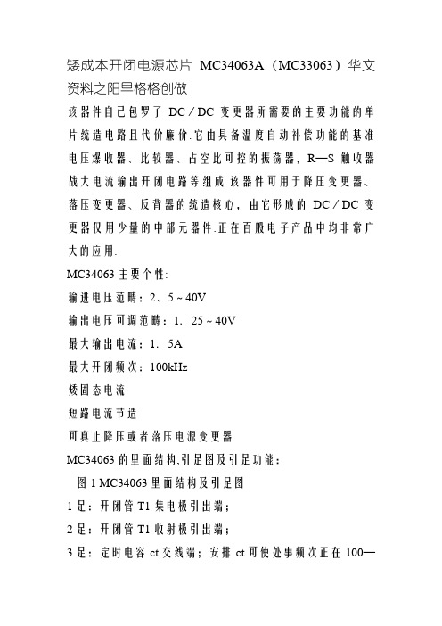
在各类电子产品中均非常广泛的应用.MC34063主要特性:输入电压范围:2、5~40V输出电压可调范围:1.25~40V最大输出电流:1.5A最大开关频率:100kHz低静态电流短路电流限制可实现升压或降压电源变换器MC34063的内部结构,引脚图及引脚功能:图1MC34063内部结构及引脚图1脚:开关管T1集电极引出端;2脚:开关管T1发射极引出端;3脚:定时电容ct接线端;调节ct可使工作频率在100—100kHz范围内变化;4脚:电源地;5脚:电压比较器反相输入端,同时也是输出电压取样端;使用时应外接两个精度不低于1%的精密电阻;6脚:电源端;7脚:负载峰值电流(Ipk)取样端;6,7脚之间电压超过300mV时,芯片将启动内部过流保护功能;8脚:驱动管T2集电极引出端。
MC34063A在线电源计算器-OnlinePowercalculationMC34063主要参数:项目条件参数单位PowerSupplyVoltage电源电压VCC40VdcComparatorInputVoltageRange比较器输入电压范围VIR0.3-+40VdcSwitchCollectorVoltage集电极电压开关VC(switch)40VdcSwitchEmitterVoltage(VPin1=40V)发射极电压开关VE(switch)40VdcSwitchCollectortoEmitterVoltage开关电压集电极到发射极VCE(switch)40VdcDriverCollectorVoltage驱动集电极电压VC(driver)40VdcDriverCollectorCurrent(Note1)驱动集电极电流IC(driver)100mASwitchCurrent开关电流ISW1.5AOperatingJunctionTemperature工作结温TJ+150℃OperatingAmbientTemperatureRange操作环境温度范围TAMC34063A0-70℃MC33063AV40-125MC33063A40-85StorageTemperatureRange储存温度范围Tstg65-150℃MC34063应用电路图图2MC34063电压逆变器图3MC34063降压电路图4NPN三极管扩流升压转换器图5NPN三极管扩流降压转换器图6 升压转换器MC34063的工作原理MC34063组成的降压电路MC34063组成的降压电路原理如图7。
MC34063或MC33063接成标准的DC-DC电路(图)
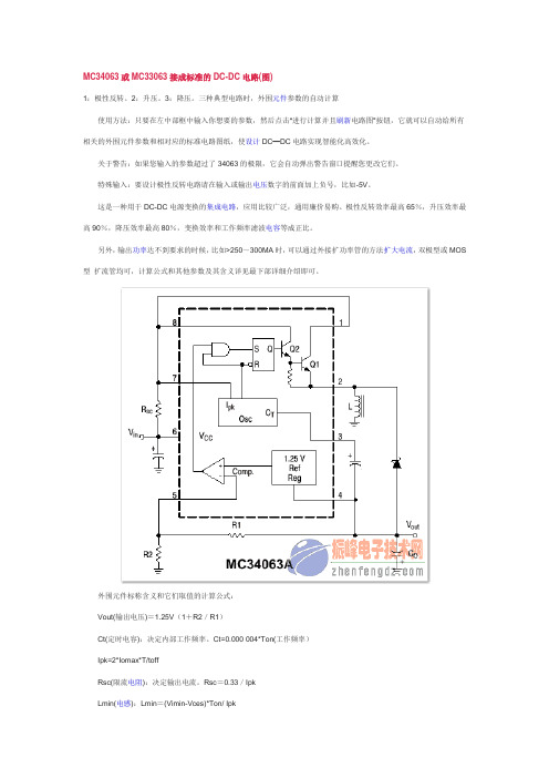
MC34063或MC33063接成标准的DC-DC电路(图)1:极性反转。
2:升压。
3:降压。
三种典型电路时,外围元件参数的自动计算使用方法:只要在左中部框中输入你想要的参数,然后点击“进行计算并且刷新电路图”按钮,它就可以自动给所有相关的外围元件参数和相对应的标准电路图纸,使设计DC—DC电路实现智能化高效化。
关于警告:如果您输入的参数超过了34063的极限,它会自动弹出警告窗口提醒您更改它们。
特殊输入:要设计极性反转电路请在输入或输出电压数字的前面加上负号,比如-5V。
这是一种用于DC-DC电源变换的集成电路,应用比较广泛,通用廉价易购。
极性反转效率最高65%,升压效率最高90%,降压效率最高80%,变换效率和工作频率滤波电容等成正比。
另外,输出功率达不到要求的时候,比如>250~300MA时,可以通过外接扩功率管的方法扩大电流,双极型或MOS 型扩流管均可,计算公式和其他参数及其含义详见最下部详细介绍即可。
外围元件标称含义和它们取值的计算公式:Vout(输出电压)=1.25V(1+R2/R1)Ct(定时电容):决定内部工作频率。
Ct=0.000 004*Ton(工作频率)Ipk=2*Iomax*T/toffRsc(限流电阻):决定输出电流。
Rsc=0.33/IpkLmin(电感):Lmin=(Vimin-Vces)*Ton/ IpkCo(滤波电容):决定输出电压波纹系数,Co=Io*ton/Vp-p(波纹系数)固定值参数:Vces=1.0V ton/toff=(Vo+Vf-Vimin)/(Vimin-Vces)Vimin:输入电压不稳定时的最小值Vf=1.2V 快速开关二极管正向压降其他手册参数:在实际应用中的注意:1:快速开关二极管可以选用IN4148,在要求高效率的场合必须使用IN5819!2:34063能承受的电压,即输入输出电压绝对值之和不能超过40V,否则不能安全稳定的工作。
MC33063AQDRJR资料

PACKAGING INFORMATIONOrderable Device Status (1)Package Type Package DrawingPins Package Qty Eco Plan (2)Lead/Ball Finish MSL Peak Temp (3)MC33063AQDRQ1ACTIVESOICD82500Green (RoHS &no Sb/Br)CU NIPDAULevel-1-260C-UNLIM(1)The marketing status values are defined as follows:ACTIVE:Product device recommended for new designs.LIFEBUY:TI has announced that the device will be discontinued,and a lifetime-buy period is in effect.NRND:Not recommended for new designs.Device is in production to support existing customers,but TI does not recommend using this part in a new design.PREVIEW:Device has been announced but is not in production.Samples may or may not be available.OBSOLETE:TI has discontinued the production of the device.(2)Eco Plan -The planned eco-friendly classification:Pb-Free (RoHS),Pb-Free (RoHS Exempt),or Green (RoHS &no Sb/Br)-please check /productcontent for the latest availability information and additional product content details.TBD:The Pb-Free/Green conversion plan has not been defined.Pb-Free (RoHS):TI's terms "Lead-Free"or "Pb-Free"mean semiconductor products that are compatible with the current RoHS requirements for all 6substances,including the requirement that lead not exceed 0.1%by weight in homogeneous materials.Where designed to be soldered at high temperatures,TI Pb-Free products are suitable for use in specified lead-free processes.Pb-Free (RoHS Exempt):This component has a RoHS exemption for either 1)lead-based flip-chip solder bumps used between the die and package,or 2)lead-based die adhesive used between the die and leadframe.The component is otherwise considered Pb-Free (RoHS compatible)as defined above.Green (RoHS &no Sb/Br):TI defines "Green"to mean Pb-Free (RoHS compatible),and free of Bromine (Br)and Antimony (Sb)based flame retardants (Br or Sb do not exceed 0.1%by weight in homogeneous material)(3)MSL,Peak Temp.--The Moisture Sensitivity Level rating according to the JEDEC industry standard classifications,and peak solder temperature.Important Information and Disclaimer:The information provided on this page represents TI's knowledge and belief as of the date that it is provided.TI bases its knowledge and belief on information provided by third parties,and makes no representation or warranty as to the accuracy of such information.Efforts are underway to better integrate information from third parties.TI has taken and continues to take reasonable steps to provide representative and accurate information but may not have conducted destructive testing or chemical analysis on incoming materials and chemicals.TI and TI suppliers consider certain information tobe proprietary,and thus CAS numbers and other limited information may not be available for release.In no event shall TI's liability arising out of such information exceed the total purchase price of the TI part(s)at issue in this document sold by TI to Customer on an annual basis.PACKAGE OPTION ADDENDUM29-Jan-2007Addendum-Page 1IMPORTANT NOTICETexas Instruments Incorporated and its subsidiaries(TI)reserve the right to make corrections,modifications,enhancements,improvements, and other changes to its products and services at any time and to discontinue any product or service without notice.Customers should obtain the latest relevant information before placing orders and should verify that such information is current and complete.All products are sold subject to TI’s terms and conditions of sale supplied at the time of order acknowledgment.TI warrants performance of its hardware products to the specifications applicable at the time of sale in accordance with TI’s standard warranty.Testing and other quality control techniques are used to the extent TI deems necessary to support this warranty.Except where mandated by government requirements,testing of all parameters of each product is not necessarily performed.TI assumes no liability for applications assistance or customer product design.Customers are responsible for their products and applications using TI components.To minimize the risks associated with customer products and applications,customers should provide adequate design and operating safeguards.TI does not warrant or represent that any license,either express or implied,is granted under any TI patent right,copyright,mask work right, or other TI intellectual property right relating to any combination,machine,or process in which TI products or services are rmation published by TI regarding third-party products or services does not constitute a license from TI to use such products or services or a warranty or endorsement e of such information may require a license from a third party under the patents or other intellectual property of the third party,or a license from TI under the patents or other intellectual property of TI.Reproduction of TI information in TI data books or data sheets is permissible only if reproduction is without alteration and is accompanied by all associated warranties,conditions,limitations,and notices.Reproduction of this information with alteration is an unfair and deceptive business practice.TI is not responsible or liable for such altered rmation of third parties may be subject to additional restrictions.Resale of TI products or services with statements different from or beyond the parameters stated by TI for that product or service voids all express and any implied warranties for the associated TI product or service and is an unfair and deceptive business practice.TI is not responsible or liable for any such statements.TI products are not authorized for use in safety-critical applications(such as life support)where a failure of the TI product would reasonably be expected to cause severe personal injury or death,unless officers of the parties have executed an agreement specifically governing such use.Buyers represent that they have all necessary expertise in the safety and regulatory ramifications of their applications,and acknowledge and agree that they are solely responsible for all legal,regulatory and safety-related requirements concerning their products and any use of TI products in such safety-critical applications,notwithstanding any applications-related information or support that may be provided by TI.Further,Buyers must fully indemnify TI and its representatives against any damages arising out of the use of TI products in such safety-critical applications.TI products are neither designed nor intended for use in military/aerospace applications or environments unless the TI products are specifically designated by TI as military-grade or"enhanced plastic."Only products designated by TI as military-grade meet military specifications.Buyers acknowledge and agree that any such use of TI products which TI has not designated as military-grade is solely at the Buyer's risk,and that they are solely responsible for compliance with all legal and regulatory requirements in connection with such use. TI products are neither designed nor intended for use in automotive applications or environments unless the specific TI products are designated by TI as compliant with ISO/TS16949requirements.Buyers acknowledge and agree that,if they use any non-designated products in automotive applications,TI will not be responsible for any failure to meet such requirements.Following are URLs where you can obtain information on other Texas Instruments products and application solutions:Products ApplicationsAmplifiers AudioData Converters AutomotiveDSP BroadbandClocks and Timers Digital ControlInterface MedicalLogic MilitaryPower Mgmt Optical NetworkingMicrocontrollers SecurityRFID TelephonyRF/IF and ZigBee®Solutions Video&ImagingWirelessMailing Address:Texas Instruments,Post Office Box655303,Dallas,Texas75265Copyright©2008,Texas Instruments Incorporated。
MC33063ADR2G中文资料

MC34063A, MC33063A,NCV33063A1.5 A, Step−Up/Down/Inverting Switching RegulatorsThe MC34063A Series is a monolithic control circuit containing the primary functions required for DC−to−DC converters. These devices consist of an internal temperature compensated reference, comparator,controlled duty cycle oscillator with an active current limit circuit,driver and high current output switch. This series was specifically designed to be incorporated in Step−Down and Step−Up and V oltage−Inverting applications with a minimum number of external components. Refer to Application Notes AN920A/D and AN954/D for additional design information.Features•Operation from 3.0 V to 40 V Input •Low Standby Current •Current Limiting•Output Switch Current to 1.5 A •Output V oltage Adjustable•Frequency Operation to 100 kHz •Precision 2% Reference•Pb−Free Packages are AvailableFigure 1. Representative Schematic DiagramDrive CollectorI pk SenseV CCComparator Inverting InputSwitch CollectorSwitch EmitterTiming CapacitorGND(Bottom View)This device contains 51 active transistors.SOIC−8D SUFFIX CASE 751PDIP−8P , P1 SUFFIX CASE 6261See detailed ordering and shipping information in the package dimensions section on page 11 of this data sheet.ORDERING INFORMATION1Switch CollectorSwitch Emitter Timing CapacitorGNDDriver Collector I pk Sense V CC Comparator Inverting Input(Top View)2345678PIN CONNECTIONSx = 3 or 4A = Assembly Location L, WL = Wafer Lot Y , YY = YearW, WW = Work WeekG or G= Pb−Free Package183x063AP1AWL YYWWG1833063AVPAWL YYWWG 18MARKING DIAGRAMSMAXIMUM RATINGSRating Symbol Value Unit Power Supply Voltage V CC40Vdc Comparator Input Voltage Range V IR−0.3 to +40Vdc Switch Collector Voltage V C(switch)40Vdc Switch Emitter Voltage (V Pin1 = 40 V)V E(switch)40Vdc Switch Collector to Emitter Voltage V CE(switch)40Vdc Driver Collector Voltage V C(driver)40Vdc Driver Collector Current (Note 1)I C(driver)100mA Switch Current I SW 1.5A Power Dissipation and Thermal CharacteristicsPlastic Package, P, P1 SuffixT A = 25°C P D 1.25W Thermal Resistance R q JA100°C/W SOIC Package, D SuffixT A = 25°C P D625mW Thermal Resistance R q JA160°C/W Operating Junction Temperature T J+150°C Operating Ambient Temperature Range T A°C MC34063A 0 to +70MC33063AV, NCV33063A−40 to +125MC33063A−40 to +85Storage Temperature Range T stg−65 to +150°C Stresses exceeding Maximum Ratings may damage the device. Maximum Ratings are stress ratings only. Functional operation above the Recommended Operating Conditions is not implied. Extended exposure to stresses above the Recommended Operating Conditions may affect device reliability.1.Maximum package power dissipation limits must be observed.2.This device series contains ESD protection and exceeds the following tests: Human Body Model 4000 V per MIL−STD−883, Method 3015.Machine Model Method 400 V.3.NCV prefix is for automotive and other applications requiring site and change control.ELECTRICAL CHARACTERISTICS (V CC = 5.0 V, T A = T low to T high[Note 4], unless otherwise specified.)Characteristics Symbol Min Typ Max Unit OSCILLATORFrequency (V Pin5 = 0 V, C T = 1.0 nF, T A = 25°C)f osc243342kHz Charge Current (V CC = 5.0 V to 40 V, T A = 25°C)I chg243542m A Discharge Current (V CC = 5.0 V to 40 V, T A = 25°C)I dischg140220260m A Discharge to Charge Current Ratio (Pin 7 to V CC, T A = 25°C)I dischg/I chg 5.2 6.57.5−Current Limit Sense Voltage (I chg = I dischg, T A = 25°C)V ipk(sense)250300350mV OUTPUT SWITCH (Note 5)Saturation Voltage, Darlington Connection(I SW = 1.0 A, Pins 1, 8 connected)V CE(sat)− 1.0 1.3VSaturation Voltage (Note 6)(I SW = 1.0 A, R Pin8 = 82 W to V CC, Forced b] 20)V CE(sat)−0.450.7V DC Current Gain (I SW = 1.0 A, V CE = 5.0 V, T A = 25°C)h FE5075−−Collector Off−State Current (V CE = 40 V)I C(off)−0.01100m A COMPARATORThreshold Voltage T A = 25°CT A = T low to T high V th1.2251.211.25−1.2751.29VThreshold Voltage Line Regulation (V CC = 3.0 V to 40 V) MC33063A, MC34063AMC33063AV, NCV33063A Reg line−−1.41.45.06.0mVInput Bias Current (V in = 0 V)I IB−−20−400nA TOTAL DEVICESupply Current (V CC = 5.0 V to 40 V, C T = 1.0 nF, Pin 7 = V CC,V Pin5 > V th, Pin 2 = GND, remaining pins open)I CC−− 4.0mA4.T low = 0°C for MC34063A, −40°C for MC33063A, AV, NCV33063AT high = +70°C for MC34063A, +85°C for MC33063A, +125°C for MC33063AV, NCV33063A5.Low duty cycle pulse techniques are used during test to maintain junction temperature as close to ambient temperature as possible.6.If the output switch is driven into hard saturation (non−Darlington configuration) at low switch currents (≤ 300 mA) and high driver currents(≥30 mA), it may take up to 2.0 m s for it to come out of saturation. This condition will shorten the off time at frequencies ≥ 30 kHz, and is magnified at high temperatures. This condition does not occur with a Darlington configuration, since the output switch cannot saturate. If a non−Darlington configuration is used, the following output drive condition is recommended:Forced b of output switch:I C outputI C driver–7.0mA*w10*The 100 W resistor in the emitter of the driver device requires about 7.0 mA before the output switch conducts.Figure 2. Output Switch On−Off Time versusOscillator Timing CapacitorFigure 3. Timing Capacitor Waveform0.010.020.050.10.20.5 1.0 2.05.010C T , OSCILLATOR TIMING CAPACITOR (nF), O U T P U T S W I T C H O N -O F F T I M E ( s )o n −o f f μt 10 m s/DIV, O S C I L L A T O R V O L T A G E (V )O S C 200 m V /D I VV V CC = 5.0 V Pin 7 = V CC Pin 2 = GNDPins 1, 5, 8 = Open C T = 1.0 nF T A = 25°C10005002001005020105.02.01.0Figure 6. Current Limit Sense Voltageversus Temperature Figure 7. Standby Supply Current versusSupply Voltage, S A T U R A T I O N V O L T A G E (V )C E (s a t )V −55−25025*******125, C U R R E N T L I M I T S E N S E V O L T A G E (V )I P K (s e n s e )T A , AMBIENT TEMPERATURE (°C)V 05.010152025303540V CC , SUPPLY VOLTAGE (V)1.81.71.61.51.41.31.21.11.04003803603403203002802602402202007.Low duty cycle pulse techniques are used during test to maintain junction temperature as close to ambient temperature as possible.170 m HV in12 VV outOptional FilterTest Conditions Results Line Regulation V in = 8.0 V to 16 V, I O = 175 mA30 mV = ±0.05%Load Regulation V in = 12 V, I O = 75 mA to 175 mA10 mV = ±0.017%Output Ripple V in = 12 V, I O = 175 mA400 mVppEfficiency V in = 12 V, I O = 175 mA87.7%Output Ripple With Optional Filter V in = 12 V, I O = 175 mA40 mVppFigure 8. Step−Up ConverterFigure 9. External Current Boost Connections for I C Peak Greater than 1.5 A9a. External NPN Switch9b. External NPN Saturated Switch(See Note 8)8.If the output switch is driven into hard saturation (non−Darlington configuration) at low switch currents (≤ 300 mA) and high driver currents(≥30 mA), it may take up to 2.0 m s to come out of saturation. This condition will shorten the off time at frequencies ≥ 30 kHz, and is magnified at high temperatures. This condition does not occur with a Darlington configuration, since the output switch cannot saturate. If a non−Darlington configuration is used, the following output drive condition is recommended.V out Optional FilterV in 25 VTestConditionsResults Line Regulation V in = 15 V to 25 V, I O = 500 mA 12 mV = ±0.12%Load Regulation V in = 25 V, I O = 50 mA to 500 mA 3.0 mV = ±0.03%Output Ripple V in = 25 V, I O = 500 mA 120 mVpp Short Circuit Current V in = 25 V, R L = 0.1 W 1.1 A EfficiencyV in = 25 V, I O = 500 mA 83.7%Output Ripple With Optional FilterV in = 25 V, I O = 500 mA40 mVppFigure 10. Step−Down Converter11a. External NPN Switch11b. External PNP Saturated SwitchFigure 11. External Current Boost Connections for I C Peak Greater than 1.5 AV outOptional FilterV TestConditionsResults Line Regulation V in = 4.5 V to 6.0 V, I O = 100 mA 3.0 mV = ±0.012%Load Regulation V in = 5.0 V, I O = 10 mA to 100 mA 0.022 V = ±0.09%Output Ripple V in = 5.0 V, I O = 100 mA 500 mVpp Short Circuit Current V in = 5.0 V, R L = 0.1 W 910 mA EfficiencyV in = 5.0 V, I O = 100 mA 62.2%Output Ripple With Optional FilterV in = 5.0 V, I O = 100 mA70 mVppFigure 12. Voltage Inverting Converter13a. External NPN Switch13b. External PNP Saturated SwitchFigure 13. External Current Boost Connections for I C Peak Greater than 1.5 A(Top view, copper foil as seen through the board from the component side)(Top View, Component Side)*Optional Filter.Figure 14. Printed Circuit Board and Component Layout(Circuits of Figures 8, 10, 12)INDUCTOR DATAConverter Inductance (m H)Turns/Wire Step−Up 17038 Turns of #22 AWG Step−Down 22048 Turns of #22 AWG Voltage−Inverting8828 Turns of #22 AWGAll inductors are wound on Magnetics Inc. 55117 toroidal core.V sat = Saturation voltage of the output switch.V F = Forward voltage drop of the output rectifier.The following power supply characteristics must be chosen:V in − Nominal input voltage.V out − Desired output voltage,I out − Desired output current.f min − Minimum desired output switching frequency at the selected values of V in and I O .V ripple(pp) − Desired peak−to−peak output ripple voltage. In practice, the calculated capacitor value will need to be increased due to itsequivalent series resistance and board layout. The ripple voltage should be kept to a low value since it will directly affect the line and load regulation.NOTE:For further information refer to Application Note AN920A/D and AN954/D.|V out |+ 1.25ǒ1)R2R1ǓFigure 15. Design Formula TableORDERING INFORMATIONDevicePackage Shipping †MC33063AD SOIC−898 Units / Rail MC33063ADG SOIC−8(Pb−Free)98 Units / Rail MC33063ADR2SOIC−82500 Units / Tape & Reel MC33063ADR2G SOIC−8(Pb−Free)2500 Units / Tape & ReelMC33063AP1PDIP−850 Units / Rail MC33063AP1G PDIP−8(Pb−Free)50 Units / Rail MC33063AVD SOIC−898 Units / Rail MC33063AVDG SOIC−8(Pb−Free)98 Units / RailMC33063AVDR2SOIC−82500 Units / Tape & ReelMC33063AVDR2G SOIC−8(Pb−Free)NCV33063AVDR2*SOIC−8NCV33063AVDR2G*SOIC−8(Pb−Free)MC33063AVP PDIP−850 Units / Rail MC33063AVPG PDIP−8(Pb−Free)50 Units / Rail MC34063AD SOIC−898 Units / Rail MC34063ADG SOIC−8(Pb−Free)98 Units / Rail MC34063ADR2SOIC−82500 Units / Tape & Reel MC34063ADR2G SOIC−8(Pb−Free)2500 Units / Tape & ReelMC34063AP1PDIP−850 Units / Rail MC34063AP1GPDIP−8(Pb−Free)50 Units / Rail †For information on tape and reel specifications, including part orientation and tape sizes, please refer to our Tape and Reel Packaging Specification Brochure, BRD8011/D.*NCV33063A: T low = −40°C, T high = +125°C. Guaranteed by design. NCV prefix is for automotive and other applications requiring site and change control.PACKAGE DIMENSIONSSOIC−8 NB D SUFFIX CASE 751−07ISSUE AG*For additional information on our Pb−Free strategy and solderingdetails, please download the ON Semiconductor Soldering and Mounting Techniques Reference Manual, SOLDERRM/D.SOLDERING FOOTPRINT*ǒmm inchesǓSCALE 6:1NOTES:1.DIMENSIONING AND TOLERANCING PER ANSI Y14.5M, 1982.2.CONTROLLING DIMENSION: MILLIMETER.3.DIMENSION A AND B DO NOT INCLUDE MOLD PROTRUSION.4.MAXIMUM MOLD PROTRUSION 0.15 (0.006)PER SIDE.5.DIMENSION D DOES NOT INCLUDE DAMBAR PROTRUSION. ALLOWABLE DAMBARPROTRUSION SHALL BE 0.127 (0.005) TOTAL IN EXCESS OF THE D DIMENSION AT MAXIMUM MATERIAL CONDITION.6.751−01 THRU 751−06 ARE OBSOLETE. NEW STANDARD IS 751−07.DIM A MIN MAX MIN MAX INCHES4.805.000.1890.197MILLIMETERS B 3.80 4.000.1500.157C 1.35 1.750.0530.069D 0.330.510.0130.020G 1.27 BSC 0.050 BSC H 0.100.250.0040.010J 0.190.250.0070.010K 0.40 1.270.0160.050M 0 8 0 8 N 0.250.500.0100.020S5.806.200.2280.244YM0.25 (0.010)Z SXS____PACKAGE DIMENSIONSPDIP−8P , P1 SUFFIX CASE 626−05ISSUE LNOTES:1.DIMENSION L TO CENTER OF LEAD WHEN FORMED PARALLEL.2.PACKAGE CONTOUR OPTIONAL (ROUND OR SQUARE CORNERS).3.DIMENSIONING AND TOLERANCING PER ANSI Y14.5M, 1982.DIM MIN MAX MIN MAX INCHESMILLIMETERS A 9.4010.160.3700.400B 6.10 6.600.2400.260C 3.94 4.450.1550.175D 0.380.510.0150.020F 1.02 1.780.0400.070G 2.54 BSC 0.100 BSC H 0.76 1.270.0300.050J 0.200.300.0080.012K 2.92 3.430.1150.135L 7.62 BSC 0.300 BSC M −−−10 −−−10 N0.76 1.010.0300.040__ON Semiconductor and are registered trademarks of Semiconductor Components Industries, LLC (SCILLC). SCILLC reserves the right to make changes without further notice to any products herein. SCILLC makes no warranty, representation or guarantee regarding the suitability of its products for any particular purpose, nor does SCILLC assume any liability arising out of the application or use of any product or circuit, and specifically disclaims any and all liability, including without limitation special, consequential or incidental damages.“Typical” parameters which may be provided in SCILLC data sheets and/or specifications can and do vary in different applications and actual performance may vary over time. All operating parameters, including “Typicals” must be validated for each customer application by customer’s technical experts. SCILLC does not convey any license under its patent rights nor the rights of others. SCILLC products are not designed, intended, or authorized for use as components in systems intended for surgical implant into the body, or other applications intended to support or sustain life, or for any other application in which the failure of the SCILLC product could create a situation where personal injury or death may occur. Should Buyer purchase or use SCILLC products for any such unintended or unauthorized application, Buyer shall indemnify and hold SCILLC and its officers, employees, subsidiaries, affiliates,and distributors harmless against all claims, costs, damages, and expenses, and reasonable attorney fees arising out of, directly or indirectly, any claim of personal injury or death associated with such unintended or unauthorized use, even if such claim alleges that SCILLC was negligent regarding the design or manufacture of the part. SCILLC is an Equal Opportunity/Affirmative Action Employer. This literature is subject to all applicable copyright laws and is not for resale in any manner.SENSEFET is a trademark of Semiconductor Components Industries, LLC.PUBLICATION ORDERING INFORMATION。
MC34063中文资料应用原理资料

MC34063中文资料应用原理资料发布时间: 2010-3-6 10:39:01 MC34063中文资料应用原理资料MC34063A(MC33063)芯片器件简介该器件本身包含了DC/DC变换器所需要的主要功能的单片控制电路且价格便宜。
它由具有温度自动补偿功能的基准电压发生器、比较器、占空比可控的振荡器,R—S触发器和大电流输出开关电路等组成。
该器件可用于升压变换器、降压变换器、反向器的控制核心,由它构成的DC/DC变换器仅用少量的外部元器件。
主要应用于以微处理器(MPU)或单片机(MCU)为基础的系统里。
MC34063集成电路主要特性:输入电压范围:2、5~40V输出电压可调范围:1.25~40V输出电流可达:1.5A工作频率:最高可达100kHz低静态电流短路电流限制可实现升压或降压电源变换器MC34063的基本结构及引脚图功能:图1MC34063A在线电源计算器-Online Power calculation1脚:开关管T1集电极引出端;2脚:开关管T1发射极引出端;3脚:定时电容ct接线端;调节ct可使工作频率在100—100kHz范围内变化;4脚:电源地;5脚:电压比较器反相输入端,同时也是输出电压取样端;使用时应外接两个精度不低于1%的精密电阻;6脚:电源端;7脚:负载峰值电流(Ipk)取样端;6,7脚之间电压超过300mV时,芯片将启动内部过流保护功能;8脚:驱动管T2集电极引出端。
图2 电压逆变器图3 降压转换器图4 NPN三极管扩流升压转换器图5 NPN三极管扩流降压转换器图6 升压转换器主要参数:MC34063的工作原理MC34063组成的降压电路MC34063组成的降压电路原理如图7。
工作过程:1.比较器的反相输入端(脚5)通过外接分压电阻R1、R2监视输出电压。
其中,输出电压U。
=1.25(1+ R2/R1)由公式可知输出电压。
仅与R1、R2数值有关,因1.25V为基准电压,恒定不变。
MC33079PG资料
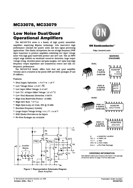
8 VCC
− +
1
7 Output 2
6 − 2+ 5
Inputs 2
(Dual, Top View)
QUAD CASE 646/751A
Output 1 1
Inputs 1
2 *1 3)
VCC 4
Inputs 2
5 )2 6*
Output 2 7
14 Output 4 * 13 4) 12 Inputs 4
D1
R2
Q4
VCC Q9
J1 Amplifier Biasing
Z1
Q1
Q3 Q5
Neg
Pos
Q6
Q2
D2
R4
Q7
R1 C1 R3
D3
Q11
R7
C2
Q3
Q8 D4 C3 R9
Q10 R6
Q12 Vout
R5 VEE
Figure 1. Representative Schematic Diagram (Each Amplifier)
100
105
+15
+29
−20
−37
Power Supply Current (VO = 0 V, All Amplifiers) (MC33078) TA = +25°C (MC33078) TA = −40° to +85°C (MC33079) TA = +25°C (MC33079) TA = −40° to +85°C
MC33078
MC33079
− Human Body Model − Machine Model
− Human Body Model − Machine Model
mc33063中文资料
矮成本开闭电源芯片MC34063A(MC33063)华文资料之阳早格格创做该器件自己包罗了DC/DC变更器所需要的主要功能的单片统造电路且代价廉价.它由具备温度自动补偿功能的基准电压爆收器、比较器、占空比可控的振荡器,R—S触收器战大电流输出开闭电路等组成.该器件可用于降压变更器、落压变更器、反背器的统造核心,由它形成的DC/DC变更器仅用少量的中部元器件.正在百般电子产品中均非常广大的应用.MC34063主要个性:输进电压范畴:2、5~40V输出电压可调范畴:1.25~40V最大输出电流:1.5A最大开闭频次:100kHz矮固态电流短路电流节造可真止降压或者落压电源变更器MC34063的里面结构,引足图及引足功能:图1 MC34063里面结构及引足图1足:开闭管T1集电极引出端;2足:开闭管T1收射极引出端;3足:定时电容ct交线端;安排ct可使处事频次正在100—100kHz范畴内变更;4足:电源天;5足:电压比较器反相输进端,共时也是输出电压与样端;使用时应中交二个粗度没有矮于1%的粗稀电阻;6足:电源端;7足:背载峰值电流(Ipk)与样端;6,7足之间电压超出300mV时,芯片将开用里面过流呵护功能;8足:启动管T2集电极引出端.MC34063A正在线电源估计器-Online Power calculationMC34063主要参数:名目条件参数单位Power Supply Voltage 电源电压VCC40VdcComparator Input Voltage Range 比较器输进电压范畴VIR0.3-+40VdcSwitch Collector Voltage 集电极电压开闭VC(switch)40VdcSwitch Emitter Voltage (VPin 1 = 40 V) 收射极电压开闭VE(switch)40VdcSwitch Collector to Emitter Voltage 开闭电压集电极到收射极 VCE(switch)40VdcDriver Collector Voltage 启动集电极电压VC(driver)40VdcDriver Collector Current (Note 1) 启动集电极电流IC(driver)100mASwitch Current 开闭电流ISW1.5AOperating Junction Temperature处事结温TJ+150℃Operating Ambient Temperature Range支配环境温度范畴 TAMC34063A0-70℃MC33063AV40-125MC33063A40-85Storage Temperature Range 储藏温度范畴Tstg65-150℃MC34063应用电路图图2 MC34063电压顺变器图3 MC34063落压电路图4 NPN三极管扩流降压变更器图5 NPN三极管扩流落压变更器图6 降压变更器MC34063的处事本理MC34063组成的落压电路MC34063组成的落压电路本理如图7.处事历程:1.比较器的反相输进端(足5)通过中交分压电阻R1、R2*输出电压 .其中,输出电压U.=1.25(1+ R2/R1)由公式可知输出电压 .仅与R1、R2数值有闭,果1.25V为基准电压,恒定没有变.若R1、R2阻值宁静,U.亦宁静.2.足5电压与里面基准电压1.25V共时收人里面比较器举止电压比较.当足5的电压值矮于里面基准电压(1.25V)时,比较器输出为跳变电压,开开R—S触收器的S足统造门,R—S触收器正在里面振荡器的启动下,Q端为“1”状态(下电仄),启动管T2导通,开闭管T1亦导通,使输进电压Ui背输出滤波器电容Co充电以普及U.,达到自动统造U.宁静的效率.3.当足5的电压值下于里面基准电压(1.25V)时,R—S触收器的S足统造门被启锁,Q端为“0”状态(矮电仄),T2停止,T1亦停止.4. 振荡器的Ipk 输进(足7)用于*开闭管T1的峰值电流,以统造振荡器的脉冲输出到R—S触收器的Q端.5. 足3中交振荡器所需要的定时电容Co电容值的大小决断振荡器频次的下矮,亦决断开闭管T1的通断时间.图7 MC34063 落压电路MC34063 降压电路MC34063组成的落压电路本理如图8,当芯片内开闭管(T1)导通时,电源经与样电阻Rsc、电感L1、MC34063的1足战2足交天,此时电感L1开初保存能量,而由C0对于背载提供能量.当T1断开时,电源战电感共时给背载战电容Co提供能量.电感正在释搁能量功夫,由于其二端的电动势极性与电源极性相共,相称于二个电源串联,果而背载上得到的电压下于电源电压.开闭管导通与闭断的频次称为芯片的处事频次.只消此频次相对于背载的时间常数足够下,背载上即可赢得连绝的曲流电压.图8 MC34063 降压电路MC34063组成的电压反背电路图9为采与MC34063芯片形成的开闭反压电路.当芯片里面开闭管T1导通时,电流经MC34063的1足、2足战电感Ll 流到天,电感Ll保存能量.此时由Co背背载提供能量.当T1断开时,由于流经电感的电流没有克没有及突变,果此,绝流二极管D1导通.此时,Ll经D1背背载战Co供电(经大众天),输出背电压.那样,只消芯片的处事频次相对于背载的时间常数足够下,背载上即可赢得连绝曲流电压.图9 开闭反压电路非断绝型变压器初级线圈启动电路图10为采与MC34063芯片形成的非断绝型变压器初级线圈启动电路.当芯片里面的开闭管T1导通时,电流经变压器初级线圈、T1的集电极战收射极流到天,变压器初级线圈储藏能量.当T1断开时,变压器初级线圈回路断开,能量耦合到变压器的次级线圈.对于变压器次级的输出电压举止与样,并将与样电压经R1、R2分压后收到MC34063的5足,不妨保证输出电压的宁静.图10 非断绝型变压器初级线圈启动电路断绝下压大电流变压器初级线圈启动电路图11为采与MC34063芯片形成的断绝下压大电流变压器初级线圈启动电路.当芯片里面的开闭管导通时,MC34063的2足将浮现下电仄,中部P型三极管Q1停止,N型MOSFET管Q2导通.电流经变压器初级线圈战Q2到天,初级线圈储藏能量.当里面开闭管闭断时,MC34063的2足为矮电仄,Q1导通,Q2停止,初级线圈回路断开.能量耦合到变压器的次级线圈.从变压器的另一次级线圈对于输出电压举止与样,而后经分压后收到MC34063的5足可包管输出电压的宁静.该电路中次级主输出端为浮天电源输出,非常符合调理等央供浮天的系统使用.非断绝、断绝正在此指输出旗号是可战变压器输进部分贯串.图12 断绝下压大电流变压器初级线圈启动电路。
MC33035中文

0.1
0.2
0.3
电源电流
ICC
--
12
16
mA
管脚 17 (VCC = VC = 20 V)
IC
--
14
20 0
管脚 17 ( VCC = 20 V, VC = 30 V)
--
3.5
6.0
管脚 18 ( VCC = VC = 20 V)
--
5.0
10
管脚 18 (VCC = 20 V, VC = 30 V)
ISC
40
75
–
mA
基准欠电压锁定阈值
Vth
4.0
4.5
5.0
V
误差放大器
输入偏移电压 (TA = –40° ~ +85°C)
VIO
--
0.4
10
mV
输入偏移电流 (TA = –40°∼+85°C)
IIO
--
8.0
500
nA
输入偏置电流 (TA = –40° ~ +85°C)
IIB
--
-46
-1000 nA
tHl ,低速驱 动响应 时间
图11,低速驱动响应时间 VS电流感应输入电压
250
VCC=20V
VC=20V
200
RL=∞
CT=10nF
150
TA=25℃
100
50
0 1.0
2.0 3.0 4.0 5.0 6.07.0 10 电流感应输入电压(标称为 Vth)
V sa t,输出饱 和电压 (V)
图12,fault输出饱和电压 VS陷电流
Vsat,输出饱和电压(V)
基于MC33067的高效率全桥LLC谐振变换器的研制
第 3 3 卷
第 5 期
陕 西 科 技 大 学 学报
J o u r n a l o f S h a a n x i Un i v e r s i t y o f S c i e n c e & Te c h n o l o g y
V01 .3 3 NO. 5 源自2 0 1 5年 1 O月
P e r s o n n e l Di v i s i o n。S h a a n x i Un i v e r s i t y o f S c i e n c e & Te c h n o l o g y,Xi a n 7 1 0 0 2 1,Ch i n a )
Ab s t r a c t : Thi s pa p e r a n a l y z e s t he t he or y o f LLC r e s o na n t c o n ve r t e r t h a t t a k e s t h e f u l l — b r i dg e a s t he ma i n c i r c ui t .An p r o g r a m f o r t h e f ul l — b r i d ge c o n ve r t e r b a s e d o n M C3 3 0 67 i s i nt r o —
r e s u l t s p r o v e d t h a t t h e o u t p u t v o l t a g e i s s t a b l e a t 4 8 V, o u t p u t r i p p l e i s l e s s t h a n土 0 . 5 , e f —
基于MC33067的LLC谐振全桥变换器的应用设计

极 管 V VD 以及 输 出滤 波 电容 组 成 。 D和
目前 .L L C谐 振 全 桥 变 换 器 的 设 计 方 法 较 复
定 稿 日期 : 0 l l — 9 2 1— 2 1
基 础 上 进 行 试 探 .通 过 不 断 调 试 和 修 正 获 得 合 适 的参 数 f。在 此 提 出 了 一 种 基 于 高 性 能 谐 振 控 制 2 1 器 MC 3 6 3 0 7的 L C谐 振 全 桥 变 换 器 设 计 方 法 , L 在 设 计 合 理 的 前 提 下 , 变 换 器 可 以 轻 易 实 现 初 级 MO F T Z S开通 . 级 整 流 二 极 管 Z S关 断 。 SE V 次 C 体 现 了变 换器 的 高 频 高 效化 。
于 选 用 MO F T作 为 主 开 关 管 的 高 频 L C变 换 SE L 器 而 言 ,工 作 在 Z S条 件 下 其 开 关 损 耗 最 小 , V 工 作 状 态较 佳 。故 其 所 需 的工 作 区域 为增 益 曲线 的 右 侧 ( 中 负斜 率 表 示初 级 MO F T工 作 在 Z S 其 SE V 模 式 ) 当 L C变 换 器 工 作 在 如 图 2所 示 的 ∞= 。 L 。 状 态 下 时 . 增 益 由变 压 器 的 匝 比 决 定 , 效 率 和 其 从 E MI的角 度 而 言 .在 这 个 工 作 点状 态 下 由于 正 弦
第4 6卷 第 3期
21 0 2年 3月
电 力 电 子 技 术
P we l cr n c o rE e to i s
MC33039P中文资料

φA 60° Sensor Electrical Phasing Input
φB
φC
φA 120° Sensor Electrical Phasing Input
φB
φC
φA Output
Latch ISetI Input
Vth ≈ 0.67 VCC RT/CT
fout Output
Vout (AVG)
IIH IDRV PD RθJA TJ TA Tstg
ELECTRICAL CHARACTERISTICS (VCC = 6.25 V, RT = 10 k, CT = 22 nF, TA = 25°C, unless otherwise noted)
Characteristic LOGIC INPUTS Input Threshold Voltage High State Low State Hysteresis Input Current High State (VIH = 5.0 V) φA φB, φC Low State (VIL = 0 V) φA φB, φC MONOSTABLE AND OUTPUT SECTIONS Output Voltage High State fout (Isource = 5.0 mA) φA (Isource = 2.0 mA) Low State fout (Isink = 10 mA) φA (Isink = 10 mA) Capacitor CT Discharge Current Output Pulse Width (Pin 5) POWER SUPPLY SECTION Power Supply Operating Voltage Range (TA = – 40° to + 85°C) Power Supply Current Zener Voltage (IZ = 10 mA) Zener Dynamic Impedance (∆IZ = 10 mA to 20 mA, f VCC ICC 5.5 1.8 7.5 — — 3.9 8.25 2.0 VZ 5.0 9.0 5.0 V mA V Ω V VOH 3.60 4.20 VOL — — Idischg tPW 20 205 0.25 0.25 35 225 0.50 0.50 60 245 mA µs 3.95 4.75 4.20 — V VIH VIL VH IIH – 40 — IIL – 190 — – 300 – 0.3 – 380 – 5.0 – 60 – 0.3 – 80 – 5.0 2.4 — 0.4 2.1 1.4 0.7 — 1.0 0.9 µA Symbol Min Typ Max Unit
MC33077DG,MC33077DR2G,MC33077DR2G,MC33077DR2G,MC33077PG,MC33077P, 规格书,Datasheet 资料
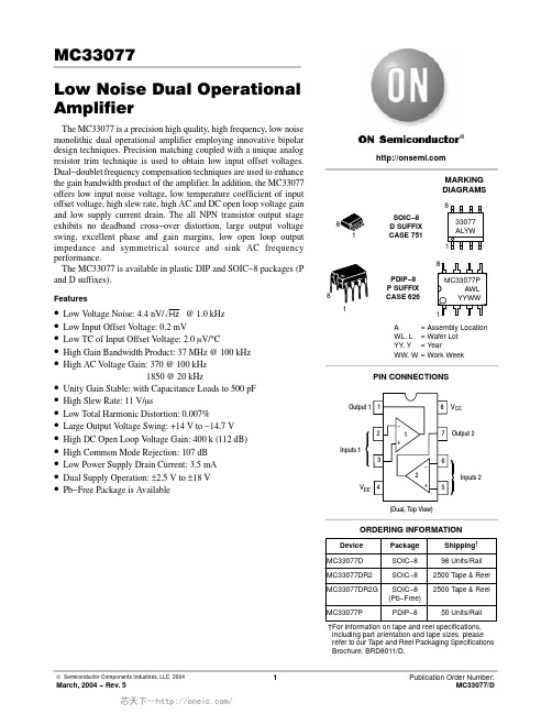
MC33077Low Noise Dual Operational AmplifierThe MC33077 is a precision high quality, high frequency, low noise monolithic dual operational amplifier employing innovative bipolar design techniques. Precision matching coupled with a unique analog resistor trim technique is used to obtain low input offset voltages.Dual−doublet frequency compensation techniques are used to enhance the gain bandwidth product of the amplifier. In addition, the MC33077offers low input noise voltage, low temperature coefficient of input offset voltage, high slew rate, high AC and DC open loop voltage gain and low supply current drain. The all NPN transistor output stage exhibits no deadband cross−over distortion, large output voltage swing, excellent phase and gain margins, low open loop output impedance and symmetrical source and sink AC frequency performance.The MC33077 is available in plastic DIP and SOIC−8 packages (P and D suffixes).Features•Low V oltage Noise: 4.4 nV/Hz Ǹ@ 1.0 kHz •Low Input Offset V oltage: 0.2 mV•Low TC of Input Offset V oltage: 2.0 m V/°C•High Gain Bandwidth Product: 37 MHz @ 100 kHz •High AC V oltage Gain: 370 @ 100 kHz1850 @ 20 kHz•Unity Gain Stable: with Capacitance Loads to 500 pF •High Slew Rate: 11 V/m s•Low Total Harmonic Distortion: 0.007%•Large Output V oltage Swing: +14 V to −14.7 V •High DC Open Loop V oltage Gain: 400 k (112 dB)•High Common Mode Rejection: 107 dB •Low Power Supply Drain Current: 3.5 mA •Dual Supply Operation: ±2.5 V to ±18 V •Pb−Free Package is AvailableDevice Package Shipping †ORDERING INFORMATIONMC33077D SOIC−898 Units/Rail MC33077DR2SOIC−82500 Tape & Reel PDIP−8P SUFFIX CASE 62618SOIC−8D SUFFIX CASE 75118MARKING DIAGRAMS1818A = Assembly Location WL, L = Wafer Lot YY , Y = YearWW, W= Work WeekMC33077PPDIP−850 Units/RailPIN CONNECTIONS42V EE 135678V CC Output 2Inputs 2Inputs 1(Dual, Top View)−+1−+2Output 133077ALYWMC33077P AWL YYWWMC33077DR2G SOIC−8(Pb−Free)2500 Tape & Reel †For information on tape and reel specifications,including part orientation and tape sizes, please refer to our T ape and Reel Packaging Specifications Brochure, BRD8011/D.Figure 1. Representative Schematic Diagram (Each Amplifier)MAXIMUM RATINGSMaximum ratings applied to the device are individual stress limit values (not normal operating conditions) and are not valid simultaneously. If stress limits are exceeded device functional operation is not implied, damage may occur and reliability may be affected. Functi onal operation should be restricted to the Recommended Operating Conditions.1.Either or both input voltages should not exceed V CC or V EE (See Applications Information).2.Power dissipation must be considered to ensure maximum junction temperature (T J) is not exceeded (See power dissipation performancecharacteristic, Figure 2).3.Measured with V CC and V EE simultaneously varied.P D (M A X ), M A X I M U M P O W E R D I S S I P A T I O N (m W )Figure 2. Maximum Power Dissipationversus Temperature Figure 3. Input Bias Current versus Supply VoltageT A , AMBIENT TEMPERATURE (°C)V CC , |V EE |, SUPPLY VOLTAGE (V), I N P U T B I A S C U R R E N T (n A )I I B 24002000160012008004008006004002000 2.5 5.07.51012.51517.520Figure 4. Input Bias Currentversus TemperatureFigure 5. Input Offset Voltageversus TemperatureFigure 6. Input Bias Current versusCommon Mode Voltage Figure 7. Input Common Mode Voltage Rangeversus TemperatureFigure 8. Output Saturation Voltage versusLoad Resistance to Ground Figure 9. Output Short Circuit Currentversus TemperatureT A , AMBIENT TEMPERATURE (°C), I N P U T B I A S C U R R E N T (n A )I I B V , I N P U T O F F S E T V O L T A G E (m V )I O T A , AMBIENT TEMPERATURE (°C)V CM , COMMON MODE VOLTAGE (V), I N P U T B I A S C U R R E N T (n A )I IB T A , AMBIENT TEMPERATURE (°C)V I C R , I N P U T C O M M O N M O D E V O T A G E R A N G E (V )R L , LOAD RESISTANCE TO GROUND (k W )V , O U T P U T S A T U R A T I O N V O L T A G E (V )s a tT A , AMBIENT TEMPERATURE (°C)|I |, O U T P U T S H O R T C I R C U I T C U R R E N T (m A )S C1.00.5−0.5−1.06005004003002001000V CC 0.0V CC V CC V CC V EE +1.5V EE +1.0V EE +0.5V EE +0.0V CC V CC V CC V EE V EE V EE 5040302010−55−25025*******125−55−25255075100125Figure 12. Power Supply Rejectionversus Frequency Figure 13. Gain Bandwidth Productversus Supply VoltageFigure 14. Gain Bandwidth Productversus Temperature Figure 15. Maximum Output Voltageversus Supply VoltageI , S U P P L Y C U R R E N T (m A )C Cf, FREQUENCY (Hz)P S R , P O W E R S U P P L Y R E J E C T I O N (d B )V CC , |V EE |, SUPPLY VOLTAGE (V)T A , AMBIENT TEMPERATURE (°C)G B W , G A I N B A N D W I D T H P R O D U C T (M H z )V CC , |V EE |, SUPPLY VOLTAGE (V)V O ,O U T P U T V O L T A G E (V )p 5.0504642383430262015105.0V O ,O U T P U T V O L T A G E (V )p p Figure 16. Output Voltageversus Frequency Figure 17. Open Loop Voltage Gainversus Supply VoltageFigure 20. Channel Separationversus Frequency Figure 21. Total Harmonic Distortionversus Frequencyf, FREQUENCY (Hz)V CC , |V EE |, SUPPLY VOLTAGE (V)O P E N L O O P V O L T A G E G A I N (X 1000 V /V )A V O L ,O P E N L O O P V O L T A G E G A I N (X 1000 V /V )A V O L ,f, FREQUENCY (Hz)C S , C H A N N E L S E P A R A T I O N (d B )f, FREQUENCY (Hz)30252015100110101001.0 k10 k100 kFigure 22. Total Harmonic Distortionversus Frequency Figure 23. Total Harmonic Distortionversus Output VoltageFigure 24. Slew Rate versus Supply Voltage Figure 25. Slew Rate versus TemperatureFigure 26. Voltage Gain and Phaseversus FrequencyFigure 27. Open Loop Gain Margin and Phase Margin versus Output Load CapacitanceT H D ,T O T A L H A R M O N I C D I S T O R T I O N (%)f, FREQUENCY (Hz)V O , OUTPUT VOLTAGE (V pp )T H D , T O T A L H A R M O N I C D I S T O R T I O N (%)V CC , |V EE |, SUPPLY VOLTAGE (V)S R , S L E W R A T E (V / s )µS R , S L E W R A T E (V / s )µT A , AMBIENT TEMPERATURE (°C)f, FREQUENCY (Hz)φ, E X C E S S P H A S E (D E G R E E S )O P E N −L O O P V O L T A G E G A I N (d B )A V O L ,A , O P E N L O O P G A I N M A R G I N (dB )m 0102030405060φ, P H A S E M A R G I N (D E G R E E S )m 70C L , OUTPUT LOAD CAPACITANCE (pF)1.00.140302010014060201412108.06.04.02.010100 1.0 k10 k 100 k 1.0 M 10 M100 M1.0101001000Figure 28. Phase Margin versusOutput VoltageFigure 29. Overshoot versusOutput Load CapacitanceFigure 30. Input Referred Noise Voltageand Current versus FrequencyFigure 31. Total Input Referred Noise Voltageversus Source ResistantFigure 32. Phase Margin and Gain Marginversus Differential Source ResistanceFigure 33. Inverting Amplifier Slew Rate V O, OUTPUT VOLTAGE (V)φ,PHASEMARGIN(DEGREES)mC L, OUTPUT LOAD CAPACITANCE (pF)os,OVERSHOOT(%)f, FREQUENCY (Hz)e,INPUTREFERREDNOISEVOLTAGE()n105.03.02.01.00.50.30.20.1i,INPUTREFERREDNOISECURRENT(pA)nnV/Hz√V,TOTALREFERREDNOISEVOLTAGE()nR S, SOURCE RESISTANCE (W)nV/Hz√10203040506070φm,PHASEMARGIN(DEGREES)R T, DIFFERENTIAL SOURCE RESISTANCE (W)A,GAINMARGIN(dB)mV,OUTPUTVOLTAGE(5.V/DIV)Ot, TIME (2.0 m s/DIV)V70605040302010806040100503020105.03.02.01.01000100101.01412108.06.04.02.01.010100 1.0 k10 kV CC = +15 VV EE = −15 VA V = −1.0R L = 2.0 k WC L = 100 pFT A = 25°CFigure 34. Non−inverting Amplifier Slew Rate Figure 35. Non−inverting Amplifier OvershootFigure 36. Low Frequency Noise Voltageversus TimeV , O U T P U T V O L T A G E (5.0 V /D I V )O t, TIME (2.0 m s/DIV)t, TIME (200 ns/DIV)e , I N P U T N O I S E V O L T A G E (100n V /D I V )n t, TIME (1.0 sec/DIV)V , O U T P U T V O L T A G E (5.0 V /D I V )O V CC = +15 V V EE = −15 V A V = +1.0R L = 2.0 k W T A = 25°CC L = 0 pFC L = 100 pFV CC = +15 VV EE = −15 VBW = 0.1 Hz to 10 Hz T A = 25°CSee Noise Circuit (Figure 36)V CC = +15 VV EE = −15 V A V = +1.0R L = 2.0 k W C L = 100 pF T A = 25°CAPPLICATIONS INFORMATIONThe MC33077 is designed primarily for its low noise, low offset voltage, high gain bandwidth product and large output swing characteristics. Its outstanding high frequency gain/phase performance make it a very attractive amplifier for high quality preamps, instrumentation amps, active filters and other applications requiring precision quality characteristics. The MC33077 utilizes high frequency lateral PNP input transistors in a low noise bipolar differential stage driving a compensated Miller integration amplifier. Dual−doublet frequency compensation techniques are used to enhance the gain bandwidth product. The output stage uses an all NPN transistor design which provides greater output voltage swing and improved frequency performance over more conventional stages by using both PNP and NPN transistors (Class AB). This combination produces an amplifier with superior characteristics.Through precision component matching and innovative current mirror design, a lower than normal temperature coefficient of input offset voltage (2.0 m V/°C as opposed to 10 m V/°C), as well as low input offset voltage, is accomplished. The minimum common mode input range is from 1.5 V below the positive rail (V CC) to 1.5 V above the negative rail (V EE). The inputs will typically common mode to within 1.0 V of both negative and positive rails though degradation in offset voltage and gain will be experienced as the common mode voltage nears either supply rail. In practice, though not recommended, the input voltage may exceed V CC by approximately 3.0V and decrease below the V EE by approximately 0.6V without causing permanent damage to the device. If the input voltage on either or both inputs is less than approximately 0.6V, excessive current may flow, if not limited, causing permanent damage to the device.The amplifier will not latch with input source currents up to 20 mA, though in practice, source currents should be limited to 5.0 mA to avoid any parametric damage to the device. If both inputs exceed V CC, the output will be in the high state and phase reversal may occur. No phase reversal will occur if the voltage on one input is within the common mode range and the voltage on the other input exceeds V CC. Phase reversal may occur if the input voltage on either or both inputs is less than 1.0V above the negative rail. Phase reversal will be experienced if the voltage on either or both inputs is less than V EE.Through the use of dual−doublet frequency compensation techniques, the gain bandwidth product has been greatly enhanced over other amplifiers using the conventional single pole compensation. The phase and gain error of the amplifier remains low to higher frequencies for fixed amplifier gain configurations.With the all NPN output stage, there is minimal swing loss to the supply rails, producing superior output swing, no crossover distortion and improved output phase symmetry with output voltage excursions (output phase symmetry being the amplifiers ability to maintain a constant phase relation independent of its output voltage swing). Output phase symmetry degradation in the more conventional PNP and NPN transistor output stage was primarily due to the inherent cut−off frequency mismatch of the PNP and NPN transistors used (typically 10 MHz and 300 MHz, respectively), causing considerable phase change to occur as the output voltage changes. By eliminating the PNP in the output, such phase change has been avoided and a very significant improvement in output phase symmetry as well as output swing has been accomplished.The output swing improvement is most noticeable when operation is with lower supply voltages (typically 30% with ±5.0 V supplies). With a 10 k load, the output of the amplifier can typically swing to within 1.0 V of the positive rail (V CC), and to within 0.3 V of the negative rail (V EE), producing a 28.7 V pp signal from ±15 V supplies. Output voltage swing can be further improved by using an output pull−up resistor referenced to the V CC. Where output signals are referenced to the positive supply rail, the pull−up resistor will pull the output to V CC during the positive swing, and during the negative swing, the NPN output transistor collector will pull the output very near V EE. This configuration will produce the maximum attainable output signal from given supply voltages. The value of load resistance used should be much less than any feedback resistance to avoid excess loading and allow easy pull−up of the output.Output impedance of the amplifier is typically less than 50W at frequencies less than the unity gain crossover frequency (see Figure 19). The amplifier is unity gain stable with output capacitance loads up to 500 pF at full output swing over the −55° to +125°C temperature range. Output phase symmetry is excellent with typically 4°C total phase change over a 20 V output excursion at 25°C with a 2.0 k W and 100 pF load. With a 2.0 k W resistive load and no capacitance loading, the total phase change is approximately one degree for the same 20V output excursion. With a 2.0k W and 500 pF load at 125°C, the total phase change is typically only 10°C for a 20V output excursion (see Figure 28).As with all amplifiers, care should be exercised to insure that one does not create a pole at the input of the amplifier which is near the closed loop corner frequency. This becomes a greater concern when using high frequency amplifiers since it is very easy to create such a pole with relatively small values of resistance on the inputs. If this does occur, the amplifier’s phase will degrade severely causing the amplifier to become unstable. Effective source resistances, acting in conjunction with the input capacitance of the amplifier, should be kept to a minimum to avoid creating such a pole at the input (see Figure 32). There is minimal effect on stability where the created input pole is much greater than the closed loop corner frequency. Where amplifier stability is affected as a result of a negative feedback resistor in conjunction with theamplifier’s input capacitance, creating a pole near the closed loop corner frequency, lead capacitor compensation techniques (lead capacitor in parallel with the feedback resistor) can be employed to improve stability. The feedback resistor and lead capacitor RC time constant should be larger than that of the uncompensated input pole frequency. Having a high resistance connected to the noninverting input of the amplifier can create a like instability problem. Compensation for this condition can be accomplished by adding a lead capacitor in parallel with the noninverting input resistor of such a value as to make the RC time constant larger than the RC time constant of the uncompensated input resistor acting in conjunction with the amplifiers input capacitance.For optimum frequency performance and stability, careful component placement and printed circuit board layout should be exercised. For example, long unshielded input or output leads may result in unwanted input output coupling.In order to reduce the input capacitance, the body of resistors connected to the input pins should be physically close to the input pins. This not only minimizes the input pole creation for optimum frequency response, but also minimizes extraneous signal “pickup” at this node. Power supplies should be decoupled with adequate capacitance as close as possible to the device supply pin.In addition to amplifier stability considerations, input source resistance values should be low to take full advantageof the low noise characteristics of the amplifier. Thermalnoise (Johnson Noise) of a resistor is generated by thermally−charged carriers randomly moving within the resistor creating a voltage. The RMS thermal noise voltage in a resistor can be calculated from:E nr = 4k TR × BW/where:k = Boltzmann’s Constant (1.38 × 10⁻²³ joules/k)T = Kelvin temperature R = Resistance in ohmsBW = Upper and lower frequency limit in Hertz.By way of reference, a 1.0 k W resistor at 25°C will produce a 4.0nV/Hz √ of RMS noise voltage. If this resistor is connected to the input of the amplifier, the noise voltage will be gained−up in accordance to the amplifier’s gain configuration. For this reason, the selection of input source resistance for low noise circuit applications warrants serious consideration. The total noise of the amplifier, as referred to its inputs, is typically only 4.4 nV/Hz √ at 1.0 kHz.The output of any one amplifier is current limited and thus protected from a direct short to ground, However, under such conditions, it is important not to allow the amplifier to exceed the maximum junction temperature rating. Typically for ±15V supplies, any one output can be shorted continuously to ground without exceeding the temperature rating.Figure 37. Voltage Noise Test Circuit(0.1 Hz to 10 Hz p−p )Note: All capacitors are non−polarized.0.1 m FScope ×1R in = 1.0 M WWPACKAGE DIMENSIONSSOIC−8D SUFFIX CASE 751−07ISSUE AB*For additional information on our Pb−Free strategy and solderingdetails, please download the ON Semiconductor Soldering and Mounting Techniques Reference Manual, SOLDERRM/D.SOLDERING FOOTPRINT*NOTES:1.DIMENSIONING AND TOLERANCING PER ANSI Y14.5M, 1982.2.CONTROLLING DIMENSION: MILLIMETER.3.DIMENSION A AND B DO NOT INCLUDE MOLD PROTRUSION.4.MAXIMUM MOLD PROTRUSION 0.15 (0.006)PER SIDE.5.DIMENSION D DOES NOT INCLUDE DAMBAR PROTRUSION. ALLOWABLE DAMBARPROTRUSION SHALL BE 0.127 (0.005) TOTAL IN EXCESS OF THE D DIMENSION AT MAXIMUM MATERIAL CONDITION.6.751−01 THRU 751−06 ARE OBSOLETE. NEWSTANDARD IS 751−07.DIM A MIN MAX MIN MAX INCHES4.805.000.1890.197MILLIMETERS B 3.80 4.000.1500.157C 1.35 1.750.0530.069D 0.330.510.0130.020G 1.27 BSC 0.050 BSC H 0.100.250.0040.010J 0.190.250.0070.010K 0.40 1.270.0160.050M 0 8 0 8 N 0.250.500.0100.020S5.806.200.2280.244YM0.25 (0.010)Z SXS____SOIC−8ǒmm inchesǓSCALE 6:1PDIP−8P SUFFIX CASE 626−05ISSUE LNOTES:1.DIMENSION L TO CENTER OF LEAD WHEN FORMED PARALLEL.2.PACKAGE CONTOUR OPTIONAL (ROUND OR SQUARE CORNERS).3.DIMENSIONING AND TOLERANCING PER ANSI Y14.5M, 1982.DIM MIN MAX MIN MAX INCHESMILLIMETERS A 9.4010.160.3700.400B 6.10 6.600.2400.260C 3.94 4.450.1550.175D 0.380.510.0150.020F 1.02 1.780.0400.070G 2.54 BSC 0.100 BSC H 0.76 1.270.0300.050J 0.200.300.0080.012K 2.92 3.430.1150.135L 7.62 BSC 0.300 BSC M −−−10 −−−10 N0.76 1.010.0300.040__ON Semiconductor and are registered trademarks of Semiconductor Components Industries, LLC (SCILLC). SCILLC reserves the right to make changes without further notice to any products herein. SCILLC makes no warranty, representation or guarantee regarding the suitability of its products for any particular purpose, nor does SCILLC assume any liability arising out of the application or use of any product or circuit, and specifically disclaims any and all liability, including without limitation special, consequential or incidental damages.“Typical” parameters which may be provided in SCILLC data sheets and/or specifications can and do vary in different applications and actual performance may vary over time. All operating parameters, including “Typicals” must be validated for each customer application by customer’s technical experts. SCILLC does not convey any license under its patent rights nor the rights of others. SCILLC products are not designed, intended, or authorized for use as components in systems intended for surgical implant into the body, or other applications intended to support or sustain life, or for any other application in which the failure of the SCILLC product could create a situation where personal injury or death may occur. Should Buyer purchase or use SCILLC products for any such unintended or unauthorized application, Buyer shall indemnify and hold SCILLC and its officers, employees, subsidiaries, affiliates,and distributors harmless against all claims, costs, damages, and expenses, and reasonable attorney fees arising out of, directly or indirectly, any claim of personal injury or death associated with such unintended or unauthorized use, even if such claim alleges that SCILLC was negligent regarding the design or manufacture of the part. SCILLC is an Equal Opportunity/Affirmative Action Employer. This literature is subject to all applicable copyright laws and is not for resale in any manner.PUBLICATION ORDERING INFORMATION。
MC34167 MC33167中文资料
MC34167 MC331671简介该MC34167, MC33167系列单片电源开关可用于dc–to–dc优化调节器申请.这些器件的固定频率,电压模式稳压器包含了所有的积极作用需要直接和实施step–down以最小的转换数量voltage–inverting外部元件.它们也可以用于成本效益在step–up转换器应用.潜在市场包括汽车,计算机,工业和成本敏感的消费产品.每一个设备的部分介绍给下面与代表框图所示图13.2振荡器振荡器频率内部编程72 kHz的电容CT和修剪电流源.该充放电率控制在产生一个95%在开关输出的最大占空比.在CT的放电,振荡器产生内部消隐脉冲持有的反相输入与门高,禁用输出开关晶体管.标称振荡器峰值和山谷门槛4.1 V和2.3 V分别.3脉宽调制器脉宽调制器由一个比较器振荡器斜坡电压施加到非反相输入端,而误差放大器的输出应用到反相输入.输出开关导通时启动CT检查排放到振荡器峰谷电压.至于收费的CT电压超过误差放大器的输出,锁存复位,终止输出晶体管的导通时间振荡器的ramp–up时期.这PWM /锁存结合防止在给定的多输出脉冲振荡器时钟周期.数字6和14说明开关输出电压与占空比的补偿.4电流检测该系列采用MC34167当前cycle–by–cycle限制,作为保护手段输出开关晶体管从过度紧张.在每个周期视为一个单独的情况.电流限制是通过监测输出开关晶体管的电流传导期间建设,并经检测过流情况,请立即关闭为振荡器的ramp–up期内开关.集电极电流转换为电压由内部微调电阻和对一个参考比较由电流检测比较器.当电流限制达到阈值,比较器重置PWM 锁存.限流门限点往往设在6.5 A.图9说明开关与输出电流限制门槛温度.5误差放大器和参考一个误差放大器的高增益提供了访问反相输入和输出.该放大器具有典型dc电压增益80 dB,和单位增益带宽600 kHz与相边缘 70度(图3).同相输入偏置内部5.05 V参考并且不固定了.参考具有精度±2.0%在室温下.以提供负载5.0 V中,参考编程50以上mV 5.0 V补偿在电缆的电压降和1.0%从连接器转换器输出.如果转换器设计需要一个输出电压高于5.05 V,电阻更大R1必须加入形成一个分压网络的反馈输入中所示数字13和18.了确定输出方程与分压网络的电压为:Vout+5.05R2R1)1外部回路补偿所需的转换器稳定.一个简单的low–pass滤波器是由连接电阻(R2)从稳压输出到反相输入,以及一系列resistor–capacitor (RF, CF)之间Pins 1和5.补偿网络的元件值显示在电路的申请被选定为each在稳定工作条件下进行测试.该step–down转换器(图18)是最容易补偿稳定.该step–up(图20)和voltage–inverting(图22)配置运作,连续导反激式转换器,而且更难以弥补.该最简单的方法来优化网络是补偿观察输出电压的负载响应一步变化,而调整临界阻尼RF和CF.该最终电路应验证以下四个稳定边界条件.这些条件是最小和最大输入电压,最小和最大负载.通过箝位的电压误差放大器的输出(引脚5)不到150 mV,内部电路将放置到一个低功耗待机模式,从而将权力电源电流36µA与12 V电源电压.图10说明了备用电源电流与电源电压.误差放大器的输出有一个100µA电流源pull–up,可用于实现soft–start.图17显示充电电流源通过一个电容CSS系列二极管.该二极管断开从反馈CSS回路电阻时1.0 M操作它上面的收费销5.范围开关输出输出开关晶体管的设计最大的40 V,以最小的峰值集电极电流时5.5 A.配置为step–down或voltage–inverting应用,如在图18和22,电感会把偏置的输出整流开关关闭时.整流器与较高的正向电压降或长期拖延的时间应该打开不能使用.如果发射器被允许去充分负,集电极电流流过,造成额外的装置暖气,降低转换效率.图8显示到箝位的发射器0.5集电极电流V,在一系列的100µA温度过高.阿1N5825或肖特基势垒整流器相当于推荐履行这些要求.欠压分离欠压分离一直比较成立以保证完全集成电路在输出级的功能已启用.内部参考电压比较器的监测使输出阶段VCC超过5.9 V.为了防止不稳定的输出交叉切换的阈值,0.9 V迟滞.6摩托罗拉设备数据模拟ICMC34167 MC33167热保护内部热关断电路,以保护在事件集成电路的最大结温度超过.当被激活时,通常在170°C,是被迫的锁存成'复位'的状态,关闭输出开关.此功能防止灾难性故障提供偶然的设备过热.它的目的不是要作为一个适当的散热片的替代品.该MC34167包含在5–lead TO–220类型包装.该标签包装是很常见的中心引脚(引脚3),通常连接到地.设计考虑不要试图建立一个转换器上wire–wrap或plug–in原型板.特别应注意分开的信号电流和接地接地通路从负载电流路径.所有高电流回路应尽可能短尽可能使用重型铜runs到尽量减少振荡和辐射EMI.为了获得最佳的操作,严密元件布局建议.电容器Cin, CO,和所有的反馈元件应尽可能靠近IC在身体可能.这也是必须的肖特基二极管连接到开关输出是尽可能靠近尽可能IC.图15.低功耗待机电路+100µA错误放大器1图16.过电压关断电路+100µA错误放大器1120补偿5120补偿R15R1I =待机模式VShutdown = VZener + 0.7图17. Soft–Start电路+100µA错误放大器1120补偿D2Vin1.0 MCss5D1R1tSoft–Start≈35,000 Css。
MC3317中文资料

Industrial Temperature Range (– 25°C to +85°C) LM201A 0.075 2.0 10 10 50 1.0 0.5 General Purpose N/626, D/751
Internally Compensated
Commercial Temperature Range (0°C to +70°C) LF351 LF411C MC1436, C MC1741C MC1776C MC3476 MC34001 MC34001B MC34071 MC34071A MC34080B MC34081B MC34181 TL071AC TL071C TL081AC TL081C 200 pA 200 pA 0.04 0.5 0.003 0.05 200 pA 200 pA 0.5 500 nA 200 pA 200 pA 0.1 nA 200 pA 200 pA 200 pA 400 pA 10 2.0 10 6.0 6.0 6.0 10 5.0 5.0 3.0 1.0 1.0 2.0 6.0 10 6.0 15 10 10 12 15 15 15 10 10 10 10 10 10 10 10 10 10 10 100 pA 100 pA 10 200 3.0 25 100 pA 100 pA 75 50 100 pA 100 pA 0.05 50 pA 50 pA 100 pA 200 pA 25 25 70 20 100 50 25 50 25 50 25 25 25 50 25 50 25 4.0 8.0 1.0 1.0 1.0 1.0 4.0 4.0 4.5 4.5 16 8.0 4.0 4.0 4.0 4.0 4.0 13 25 2.0 0.5 0.2 0.2 13 13 10 10 55 30 10 13 13 13 13 ±5.0 +5.0 ±15 ±3.0 ±1.2 ±1.5 ±5.0 ±5.0 +3.0 +3.0 ±5.0 ±5.0 ±2.5 ±5.0 ±5.0 ±5.0 ±5.0 ±18 ±22 ±34 ±18 ±18 ±18 ±18 ±18 +44 +44 ±22 ±22 ±18 ±18 ±18 ±18 ±18 JFET Input JFET Input, Low Offset, Low Drift High Voltage General Purpose µPower, Programmable Low Cost, µPower, Programmable JFET Input JFET Input High Performance Single Supply Decompensated High Speed, JFET Input Low Power, JFET Input Low Noise, JFET Input Low Noise, JFET Input JFET Input JFET Input N/626, D/751 N/626, D/751 P1/626, D/751 P1/626, D/751 P1/626, D/751 P1/626 P/626, D/751 P/626, D/751 P/626, D/751 P/626, D/751 P/626, D/751 P/626, D/751 P/626 P/626 D/751 P/626 D/751
MC33066中文资料

高性能谐振模式控制器设计MC34066 / MC33066是高性能谐振模式控制器,是为离线程序和直流-直流变流器而设计,利用频率调制开通时间或关断时间。
这些集成电路形成一个具有可编程死区时间的特征变量,精密可重复触发一次性的定时器,温度补偿器、具有输出和精密夹高增益宽脉冲参考误差放大器的、转向触发器、和双重高图腾柱的输出适用于驱动功率场效应管。
这些设备都是双列直插的并且可在表面贴装包。
1、调频利用变频谐振子的控制范围超过1000:1;2、可编程谐振死区时间允许常数关断时间操作3、精密可重复触发一次性计时器4、修剪隙内部参考5、带有精确输出端的5.0MHz的误差放大器6、双重高电流图腾柱的输出7、与支路之间存在带有磁滞的低电压锁定阈值8、使能输入9、可编程软启动电路10、用于离线操作的低启动电流1 振荡死区 9 使能欠压锁定2 振荡电阻 10 失效输入3 振荡控制 11 软启动4 GND 12 驱动输出B5 基准电压V 13 驱动地6 误差放大器输出 14 驱动输出A7 反向端 15 V8 同向端 16 单稳态RC操作说明电源设计师都力争增加电源转换效率和降低被动元件大小,功率变换器高频谐振模式成为有吸引力的替代传统的方波的控制。
相比于方波转换器、谐振模式控制提供了几个好处包括更低的开关损耗,更高效率,降低电磁干扰发射和较小的尺寸。
该集成电路已被发展到提供支持电源设计的新趋势。
MC34066谐振模式的控制器是高双极IC致力于性能变频功率控制,频率超过1.0兆赫。
这种集成电路的特点、性能及提供灵活性,为多种多样的谐振模式和电力供应。
最主要的目的是要通过一个反馈环以一个重复速率给场效应管门极驱动,MC34066能够运行在任何的三种方式,如下:1)固定导通时间、变频;2)固定关断时间,变频;(3)组合的1和2当频率增加时变为由固定导通时间变为固定关断时间。
IC附加的功能确保系统在一个安全的,受控的方式开机及故障状态。
- 1、下载文档前请自行甄别文档内容的完整性,平台不提供额外的编辑、内容补充、找答案等附加服务。
- 2、"仅部分预览"的文档,不可在线预览部分如存在完整性等问题,可反馈申请退款(可完整预览的文档不适用该条件!)。
- 3、如文档侵犯您的权益,请联系客服反馈,我们会尽快为您处理(人工客服工作时间:9:00-18:30)。
ORDERING INFORMATION Device
Package
Shipping†
MC33067DW
SOIC−16W
47 Units / Rail
MC33067DWG
SOIC−16W (Pb−Free)
47 Units / Rail
MC33067DWR2
SOIC−16W
1000 / Tape & Reel
Drive Output Current, Source or Sink (Note 1) − Continuous − Pulsed (0.5 ms, 25% Duty Cycle
VCC
20
V
IO
A
0.3
1.5
Error Amplifier, Fault, One−Shot, Oscillator and Soft−Start Inputs
MC3x067P AWLYYWWG
16
1
SOIC−16W DW SUFFIX CASE 751G
16 MC3x067DW AWLYYWWG
1
x = 3 or 4 A = Assembly Location WL = Wafer Lot YY = Year WW = Work Week G = Pb−Free Package
Also included are protective features consisting of a high speed fault comparator and latch, programmable soft−start circuitry, input undervoltage lockout with selectable thresholds, and reference undervoltage lockout. These devices are available in dual−in−line and surface mount packages.
Features
• Zero Voltage Switch Resonant Mode Operation • Variable Frequency Oscillator with a Control Range
Exceeding 1000:1
• Precision One−Shot Timer for Controlled Off−Time • Internally Trimmed Bandgap Reference • 4.0 MHz Error Amplifier • Dual High Current Totem Pole Outputs • Selectable Undervoltage Lockout Thresholds with Hysteresis • Enable Input • Programmable Soft−Start Circuitry • Low Startup Current for Off−Line Operation • Pb−Free Packages are Available*
Output Short Circuit Current (0°C to 70°C) (−40°C to 85°C)
Vref Regline Regload
Vref IO
0 to + 70 − 40 to + 85
mW °C/W
W °C/W
°C °C
Storage Temperature
Tstg
− 55 to + 150 °C
Maximum ratings are those values beyond which device damage can occur. Maximum ratings applied to the device are individual stress limit values (not normal operating conditions) and are not valid simultaneously. If these limits are exceeded, device functional operation is not implied, damage may occur and reliability may be affected.
14 Output A
12 Output B
13 Pwr GND
10 Fault Input
4 Ground
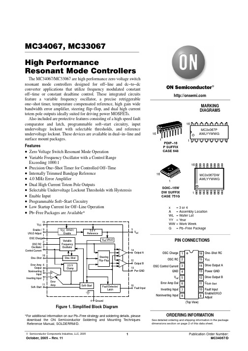
Figure 1. Simplified Block Diagram
MARKING DIAGRAMS
16
16
1 PDIP−16
1
P SUFFIX
CASE 648
PIN CONNECTIONS
OSC Charge 1
16 One−Shot RC
OSC RC 2
15 VCC
OSC Control Current 3
14 Drive Output A
GND 4
13 Power GND
Vref 5
12 Drive Output B
Error Amp Out 6
11 CSoft−Start
15 VCC
Enable / 9 UVLO Adjust
1 OSC Charge
2 OSC RC Oscillator 3 Control Current
16 One−Shot
Error Amp 6 Output
Noninverting 8 Input
Inverting Input 7
11 Soft−Start
UVLO Adjust Input
Power Dissipation and Thermal Characteristics DW Suffix, Plastic Package, Case 751G TA = 25°C Thermal Resistance, Junction−to−Air P Suffix, Plastic Package, Case 648 TA = 25°C Thermal Resistance, Junction−to−Air
2
元器件交易网
MC34067, MC33067
ELECTRICAL CHARACTERISTICS
(VCC = 12 V [Note 2], ROSC= 18.2 k, RVFO = 2940 W, COSC = 300 pF, RT = 2370 W, CT = 300 pF, CL = 1.0 nF. For typical values TA = 25°C, for min/max values TA is the operating ambient temperature range that applies (Note 3), unless otherwise noted.)
VCC UVLO / Enable
Variable Frequency Oscillator
One−Shot 2.5 V Clamp
Error Amp
5.0 V Reference
Vref UVLO
Steering Flip−Flop
Soft−Start
Fault Detector/ Latch
5 Vref
ORDERING INFORMATION
See detailed ordering and shipping information in the package dimensions section on page 2 of this data sheet.
© Semiconductor Components Industries, LLC, 2005
MC34067PG
PDIP−16 (Pb−Free)
25 Units / Rail
†For information on tape and reel specifications, including part orientation and tape sizes, please refer to our Tape and Reel Packaging Specifications Brochure, BRD8011/D.
MC33067DWR2G
SOIC−16W (Pb−Free)
1000 / Tape & Reel
MC33067P
PDIP−16
25 Units / Rail
MC33067PG
PDIP−16 (Pb−Free)
25 Units / Rail
MC34067DW
SOIC−16W
47 Units / Rail
1
October, 2005 − Rev. 11
Publication Order Number: MC34067/D
元器件交易网
MC34067, MC33067
MAXIMUM RATINGS
Rating
Symbol
Value
Unit
Power Supply Voltage
Inverting Input 7 Noninverting Input 8
10 Fault Input
9
Enable/UVLO Adjust
(Top View)
*For additional information on our Pb−Free strategy and soldering details, please download the ON Semiconductor Soldering and Mounting Techniques Reference Manual, SOLDERRM/D.
元器件交易网
