诺控通讯技术16-Port串口服务器器用户手册v2.0
NetCommander 16-Port Cat5 KVM over IP Switch 用户手册说

Management SoftwareFree NetCommander-AXS Management Software is available for access and control of all of your NetCommander IP KVM switches (B070 and B072 Series). From a single interface, you can access server ports on any of your KVM switches, power cycle or power on/off outlets of IP PDUs, and manage KVM settings. This software can be found on the model support page of the B072-016-1-IP, or via searching NetCommander-AXS on https://NetCommander 16-Port Cat5 KVM over IP Switch - 1 Remote + 1 Local User, 1U Rack-MountMODEL NUMBER:B072-016-1-IPControl up to 16 computers from virtually anywhere with one Cat5 KVM switch. This KVM switch with IP remote access is a smart solution for efficient server control. Low-cost Cat5 cables let you locate servers up to 100 ft. away.DescriptionThe B072-016-1-IP KVM Switch is the optimal solution for controlling up to 16 computers/servers locally, from across the room, down the street or around the globe on a network or the Internet.This KVM switch can be accessed and controlled remotely, so there’s no need to travel to the server room or network closet. A Java-based application allows access via web browser from any secure IP connection; a non-browser client that can bypass browser-related Java Security prompts is available.The B072-016-1-IP uses inexpensive, user-supplied Cat5e/6/6a cabling with Server Interface Units (sold separately) so you can connect computers/servers located up to 100 feet away from the switch. This switch features dual Ethernet ports; if one fails, the other takes over, keeping remote access uninterrupted. Users can switch easily between the 16 ports using an on-screen display (OSD), hotkey commands or a remote toolbar. Multi-level password protection prohibits unauthorized users from accessing connected computers, and a local user and a remote user can each log on and access different ports simultaneously.Two serial ports allow control of serial-manageable devices such as IP PDUs, firewalls and routers; individual ports can be assigned to an IP PDU port to power on/off the server connected to that port. This KVM switch is compatible with Windows and Linux operating systems, and provides remote access using a Windows computer. It supports VGA video resolutions up to 1920 x 1080 at 60 Hz. Heavy-duty steel housing stands up to frequent use.Virtual Media allows an .iso file to be mounted to a target server and accessed as if it were stored directly on it. Virtual Media data transfer rates up to 12 Mbps are supported when using a B078-101-USB2 Server Interface Unit. Other features include RADIUS and LDAP/S authentication, system-sent SNMP messaging and an event log that tracks logins, reboots and network setting changes.Free NetCommander-AXS Management Software is available to access and control all of your NetCommander® IP KVM switches (B070 and B072 Series). From a single interface, you can access server ports on any of your KVM switches, power cycle or power on/off outlets of IP PDUs and manage Highlights16-port KVM switch providescontrol of computers/serverslocally or via your network or the InternetqOccupies just 1U of rack space qLow-cost Cat5 cabling allowslonger distances, reduces cable clutterqSimultaneous support for 2users – 1 local, 1 remoteqDual Ethernet ports assureuninterrupted remote accessqCompliant with the FederalTrade Agreements Act (TAA) for GSA Schedule purchasesqSystem RequirementsComputer with HD15 (VGA)port, and USB port or PS/2keyboard/mouse portsqUser-supplied Cat5e/6/6acablingqB078-101-USB-1 (USB), B078-101-USB2 or B078-101-PS2(PS/2) Server Interface Unit isrequired for each connectedcomputer/serverqFor computers with DisplayPortor HDMI, change to VGA usingadapters P134-06N-VGA-V2 orP131-06N. Maximum videoresolutions using adapters mayvary.qCompatible with Windows andLinux operating systemsqRemote access supported using Windows computersqRemote console computersrequire minimum Pentium 4 with2 GB memoryqHardware VersionsA new hardware version (v2) of the B072-016-1-IP was released in 2014, requiring different firmware from the previous version (v1). The Support tab of this page includes a zip folder for v1. Along with the applicable firmware, it contains an FW Notes file to help you determine which hardware version you have and which firmware to use. The current firmware comes pre-installed on all v2 models.KVM settings. This software can be downloaded free of charge from the model support page for the B072-016-1-IP. Compliant with the Federal Trade Agreements Act (TAA) for GSA Schedule purchases. FeaturesSaves Space and MoneyMounts in a standard 19 in. rackqInexpensive Cat5e/6/6a cabling lets you locate servers up to 100 ft. from the switchqUse a Server Interface Unit, B078-101-USB-1 (for USB) or B078-101-PS2 (for PS/2) with each server to be connected with Cat5 cable; use a B078-101-USB2 to support Virtual Media data transfer rates up to 12 MbpsqTo convert DisplayPort or HDMI computers to VGA, use adapters P134-06N-VGA-V2 or P131-06N. Maximum video resolutions using adapters may vary.qIP Remote Access for Fewer Trips to the Server RoomControl this KVM switch over IP: remote access means there’s no need to travel to the server room or network closetqJava-based application allows Windows computers to control a target server via web browser from any location over a secured IP connectionqA non-browser client is available that allows Windows computers to remotely access the KVM without the need for a browser and without the need to install Javaq1 local + 1 remote user can access different ports concurrently; up to 5 users can share a single remote sessionqSupports both IPv4 and IPv6qSimplifies IT TasksOn-screen display, hot keys and remote toolbar for easy useqFree NetCommander-AXS Management Software gives you remote access and control over all your NetCommander IP KVM switches (B070 and B072 series)qVideo resolutions up to 1920 x 1080 @ 60 Hz are supportedq2 serial ports allow control of serial-manageable devices such as IP PDUs, firewalls and routers; assign individual ports to an IP PDU port to power on/off the server connected to that portqBIOS-level control of any brand and model server, regardless of the server’s condition and network connectivityqVirtual Media allows an .iso file to be mounted to a target server and accessed as if it were directly stored on itqVirtual Media data transfer rates up to 12 Mbps are supported when using a B078-101-USB2 Server Interface Unit; a B078-101-USB-1 Server Interface Unit can be used for Virtual Media support, but only at speeds up to 1MbpsqFast Virtual Media KVM System patented under Pat. No. US 9,417,720qSystem-sent messages to SNMP server notify you of network failuresqSupports RADIUS and LDAP/S authenticationqLog tracks events such as logins, reboots and network setting changes on your installationqAdvanced Security FeaturesMulti-level password protection: create administrator accounts with full access and user accounts with limited accessqSupports TLS 1.2 security protocolqYou can install SSL certificates to ensure secure transactions between web servers and browsersqBuilt to LastFlash-upgradable firmware over the networkqHeavy-duty steel housing stands up to frequent useqTAA Compliant Package Includes16-Port Cat5 1+1 User 1URack-Mount VGA USB KVMSwitch with IP Remote Access qC13 to 5-15P Power CordqRack-Mount HardwareqCD with Owner's ManualqQuick Start GuideqSpecificationsCompliant with the Federal Trade Agreements Act (TAA) for GSA Schedule purchasesq© 2023 Eaton. All Rights Reserved. Eaton is a registered trademark. All other trademarks are the property of their respective owners.。
PRO16-III抄控器功能及使用说明书

PRO16-III抄控器功能及使用说明青岛东软载波科技股份有限公司1.用途及使用范围PRO16-III型抄控器和掌上电脑或计算机、载波表一起构成了EASTSOFT®远程集中抄表系统(AMR)的主动发送设备,实现载波通信功能,利用低压电力线为通信介质与终端设备(载波电能表)建立可靠的数据连接,并以半双工的通信方式对终端设备进行抄控操作。
主要应用在集抄系统的现场安装、生产调试等环节。
2.功能及特点PRO16-III型抄控器采用东软公司自主研制开发的低压电力线载波通信发送芯片PLCi38-III,数据链路层采用高级数据链路控制协议,应用层兼容DL/T645—2007规约。
PRO16-III型抄控器和掌上电脑或计算机配合使用能完成以下功能:●设置参数:通过电力线设置和修改载波电表参数。
●抄读参数:具有指定抄读一只电表数据:表号、初始电量、初始密码等●监控单表:可以对单表进行实时监控其主要特点是:数据传输可靠,抗干扰能力强,外形小巧便于携带,是实现场维护不可缺少的必要设备。
3.工作原理及结构3.1.结构图3.2.工作原理抄控器通过RS232串行口或USB口接收主站(手持设备或计算机)的抄控命令,经载波芯片PLCi38-III扩频调制、发射馈网电路选频放大后,传送到低压电力线上;电力线终端设备(载波电能表)收到命令后向抄控器返回应答,通过RS232串行口或USB 实现通信。
4.规格和主要的技术参数5.抄控器通讯说明5.1.掌机软件版本1.支持规约类型:DL/T645-1997通讯协议、DL/T645-2007通讯协议;2.软件下载方式:登陆东软网站/选择‘技术支持’,在‘掌机软件’栏里有各版本程序的下载链接;3.具体抄读电表类型与版本的对应关系如下:5.2. 连接PC 机通讯5.2.1.通讯连接示意图注意:A/B 接线图1 基本测试使用图2 测试通讯效果5.2.2. 通讯软件说明1. 支持规约类型:DL/T645-1997通讯协议、DL/T645-2007通讯协议;2. 软件下载方式:登陆东软网站/选择‘技术支持’,在‘软件及文档下载’调试软件栏里有“DL/T645 - 1997协议调试器(V2.13)”和“DL/T645 - 2007协议调试器”的下载;3. 以下以DL/T645 - 1997协议调试器(V2.13)软件为例说明使用方法 a) 运行参数设定软件运行后首先显示如下参数界面:可以指定串口参数,如左图所示;切换到电表参数页面中可以设定电表的通讯密码等参数,电表参数中的“电表密码”项目即07-645规约中的02级密码,电表参数中的“低级密码”项目即07-645规约中的04级密码b)电表数据项单项操作在如下主界面中,录入表号以后,可以选择操作的控制码,如读数据、写数据、广播校时、冻结命令、电表清零等如果选择的是读数据和写数据,需要填写数据标识内容,也可以点击数据标识来进行数据项选择,弹出如下界面,从中可以选择需要操作的数据项目选择完毕,即可点击发送按钮来执行电表操作,在消息栏目中可以看到软件与电表的交互报文,在状态栏中可以看到返回报文的数据体内容,下图所示的是抄读电表“800000000001”的“00010000当前正向有功总电量”数据,返回的数据内容是00008463,参照规约解析是84.63kWh注意事项:✧通讯速率:9600bps,数据位:8位,停止位:1位,校验方式:偶校验;✧如果需要对电表进行设置,需要输入8位电表密码(6位密码加2位权限);✧如果采用采集器方式对电表通讯,根据需要选中“通过采集器进行抄读”,并正确输入采集器地址;✧如有需要需要选中“命令帧前使用前导符”按钮,同时前导符输入:FC,次数为:1;以上设置完成后,打开串口,退回到主界面,输入表号,然后选择通讯类型以及数据标识,进行通讯即可;详细的通讯收发报文将会在窗体空白出显示;关于该软件详细的说明,参见软件包中的用户手册。
串口服务器使用手册

QZ06-232/NET 串口服务器使用手册重庆勤智科技有限公司第一章设备介绍....................... 错误!未定义书签。
设备简介......................... 错误!未定义书签。
产品特点......................... 错误!未定义书签。
产品参数......................... 错误!未定义书签。
第二章设备使用....................... 错误!未定义书签。
设备外观及接口....................... 错误!未定义书签。
设备使用介绍....................... 错误!未定义书签。
使用前连接..................... 错误!未定义书签。
配置设备参数.................... 错误!未定义书签。
配置设备的连接方式............... . 错误!未定义书签。
连接设备.................... 错误!未定义书签。
配置界面.................... 错误!未定义书签。
网络设置.................... 错误!未定义书签。
系统设置.................... 错误!未定义书签。
串口设置.................... 错误!未定义书签。
连接统计.................... 错误!未定义书签。
设备使用...................... 错误!未定义书签。
设备连接计算机测试............... . 错误!未定义书签。
设备配合虚拟串口使用............. .. 错误!未定义书签。
双设备点对点连接................. 错误!未定义书签。
恢复出厂设置.................. 错误!未定义书签。
第三章常见问题....................... 错误!未定义书签。
YT-CM6020-G-F16G4 变电站网络交换机使用说明书
变电站网络交换机使用说明书深圳市源拓光电技术有限公司(以下简称“源拓光电”)为客户提供全方位的技术支持和服务。
直接向源拓光电购买产品的用户,如果在使用过程中有任何问题,可与源拓光电各地办事处或用户服务中心联系,也可直接与公司总部联系。
读者如有任何关于源拓光电产品的问题,或者有意进一步了解公司其他相关产品,可通过下列方式与我们联系:公司网址:技术支持热线:(0755)26641737技术支持传真:(0755)26640197技术支持邮箱:market@技术文档邮箱:market@客户投诉热线:(0755)26641737公司总部地址:深圳市宝安区石岩街道石龙仔社区森海诺科创大厦11-12楼邮政编码:528109―――――――――――――――――――――――――――――――――――――――――――――声明©copyright2016by Shenzhen Wintop Optical Technology Co.,Ltd.All rights reserved.源拓光电科技发展股份有限公司版权所有,保留一切权利。
非经本公司书面许可,任何单位和个人不得擅自摘抄、复制本书内容的部分或全部,并不得以任何形式传播。
是源拓光电科技发展股份有限公司的注册商标。
对于本手册中出现的其它商标,由各自的所有人拥有。
由于产品版本升级或其它原因,本手册内容会不定期进行更新。
除非另有约定,本手册仅作为使用指导,本手册中的所有陈述、信息和建议不构成任何明示或暗示的担保目录1概述 (6)2维护界面登录 (6)3产品信息 (6)4管理IP设置 (7)4.1IP地址简介 (7)4.2管理IP地址维护界面 (8)5用户管理 (8)6端口 (9)6.1端口设置 (9)6.2光口千百兆设置 (10)6.3端口限速 (11)6.4镜像配置 (11)6.5光模块信息 (12)6.6端口统计 (13)6.7静态单播MAC地址表 (14)6.8TRUNK (14)7VLAN配置 (15)7.1VLAN概述 (15)7.2VLAN的成员配置 (15)7.3VLAN的端口配置 (16)8QoS (16)8.1QoS概述 (16)8.2常用优先级介绍 (17)8.3队列调度介绍 (17)8.4QoS模式设置界面 (18)8.5端口优先级 (18)8.6Cos映射界面 (18)8.7Dscp映射界面 (19)8.8QoS端口信任模式界面 (19)9STP (20)9.1生成树简介 (20)9.2spanning tree设置 (20)9.3spanning tree端口 (21)9.4spanning tree信息 (21)10LLDP (22)10.2LLDP设置 (22)10.3LLDP端口 (23)10.4LLDP信息 (23)10.5LLDP统计 (24)11恢复出厂设置 (25)12配置文件管理 (25)1361850配置文件管理 (26)14保存重启 (27)15退出 (27)16静态组播MAC地址 (28)17GMRP功能配置 (28)17.1GMRP定义 (28)17.2GMRP维护界面 (28)18IGMP snooping设置 (29)18.1IGMP原理 (29)18.2IGMP设置 (29)18.3IGMP路由端口 (30)18.4IGMP统计 (30)18.5IGMP组 (31)19组播流量限速 (32)20VLAN组播选项 (32)21Dos攻击防御 (33)22告警管理 (33)22.1简介 (33)22.2安全设置 (33)23风暴抑制 (33)24端口MAC地址绑定 (34)25端口MAC地址学习限制 (34)26VLAN MAC地址学习限制 (35)27非法访问控制 (35)28SV报文延时累加 (36)29SV报文限速 (36)30GOOSE报文限速 (37)31电力报文优先级设置 (37)32SNTP及系统时间 (38)32.1SNTP简介 (38)33SNMP设置 (39)33.1SNMP简介 (39)33.2SNMP视图 (39)33.3SNMP团体 (39)33.4SNMP群组 (40)33.5SNMP用户 (40)33.6SNMP主机 (41)34日志管理 (41)34.1日志主机设置 (41)34.2系统日志 (42)34.3告警日志 (42)1概述YT-CM6020-G-F16G4维护界面手册用于指导设备调试人员应如何正确通过维护界面配置需要的功能。
Tripp Lite B092-016 16-Port 串行控制台 终端服务器说明说明书

16-Port Serial Console / Terminal Server with Built-in PowerAlert and KVM inputsMODEL NUMBER:B092-016DescriptionTripp Lite's B092-016 Console / Terminal Server with PowerAlert will let you manage all the equipment in your data center or computer room, either remotely or from the rack itself. Manage your computers at the service processor level (IPMI, SoL, web browser), operating system level (Windows, Linux, VMWare) and right up to the applications layers (RDP, VNC, HTTP). Use any of the 4 USB ports or 16 serial ports to control your UPS systems and PDU switches, manage the serial consoles on your routers as well as the web browser network ports on your firewalls and other devices. This local access to all the consoles gives you complete control over the entire headed and headless infrastructure in your racks. Full in-band and out-of-band connection provides you 24/7 access to monitor and control all your equipment, either right from the rack, or from a remote site via browser or SDT Connector client. Supports 3G cellular out-of-band access. The USB port on the console server is compatible with the Pantech ULM290 VZW and the following Sierra Wireless USB modems; Compass 888, USB 598, USB 598U, USB 312U, USB 308, and U313. You can customize your monitoring and alert capabilities, and maintain extensive logs. SDT for Nagios-support provides an even more sophisticated alarm and notification mechanism with escalation rules to alert you of breached thresholds and potential problems. You can monitor network services (SMTP, POP3, HTTP, NNTP, ICMP, SNMP, FTP, SSH), host resources (processor load, disk usage, system logs) and probes (temperature, alarms...) with automatic alerts for defined system events sent via e-mail, SNMP and SMS to mitigate system and network disasters. Remote management access to theB092-016 (using browsers, VNC, RDP, SSH, Telnet) is securely tunneled with strong selectable encryption (3DES, Blowfish, AES, Arcfour), flexible authentication, (Public Key, One-Time Password, Kerberos, LDAP, TACACS) and access control (trusted networks, dial back, restricted user access zones). Compliant with the Federal Trade Agreements Act (TAA) for GSA Schedule purchases. Constructed of heavy-duty steel housing.FeaturesRemote Desktop (RDP) access to Windows XP/Vista/2003/Terminal Servicesq HighlightsBuilt-in PowerAlert PowerManagement SoftwareqSecure In-band and Out-of-band access for a host of networkdevicesqManage all equipment in theRack: Servers, UPS, PDU,Routers, Switches, Firewalls, etc qCompliant with the FederalTrade Agreements Act (TAA) for GSA Schedule purchasesqSupports 3G cellular out-of-band accessqConfigured to use standardCat5e/6 patch cable whenconnecting to Cisco devicesqValidated to meet FIPS 140-2standardsqPackage IncludesB092-016, 16-Port IP ConsoleServer w/PowerAlertqRackmount hardwareq2 x 6ft, Cat5e Patch cablesq1 x DB9F - RJ45 CrossoverAdapterq1 x DB9F - RJ45 Straight-Through Adapterq1 x 6ft, 5-15P to C13 PowercableqCD with ManualqConfigured to use standard Cat5e/6 patch cable when connecting to Cisco devicesqTripp Lite's console servers all use an embedded FIPS 140-2 OpenSSL cryptographic module that has qbeen validated to meet the FIPS 140-2 standards and has received Certificate #1051.When using SSH, HTTPS or SDT Connector to connect to any service on the console server whileqrunning in FIPS mode, they will be utilizing the embedded FIPS compliant module. In order to connect using any of the protocols, you must use a cryptographic algorithm that is FIPS approved or it will fail. Supports 3G cellular out-of-band access. The USB port on the console server is compatible with theqPantech ULM290 VZW and the following Sierra Wireless USB modems; Compass 888, USB 598, USB 598U, USB 312U, USB 308, and U313.VNC access to Sun/Window/Linux computersqICA access to CitrixqFirefox HTTP(S) access to browser controlled appliances with Java support (SUN JRE)qNative IPMI 1.5 and 2.0 (RMCP/RMCP+) support for BMC and service processor access and control qSecure SOL (Serial over LAN) access to BIOS, EMS and ACSqService processor access (IPMI, ILO, LOM and more)qAccess to KVM built in to service processors (DRAC, RSA)qEmbedded FIPS140-2 cryptographic module, Certificate #1051qIP SEC VPN and Secure Shell (SSH V2 and V3).qBreak over SSH supportqPort triggers with SMNP and email alertsqOffline data logging (Syslog, NFS, CIFS)qOnline data buffering and loggingqMultiple users per port (with port sniffing)qTelnet/SSH/Raw TCP connectqRFC 2217 - port redirectionqIntegrated AJAX serial console and system terminal via web interfaceqSecure Shell (SSH V2 and V3)qTACACS+ , RADIUS and LDAP authenticationqPAP/CHAP authentication (dial up) and dial backqLocal authenticationqSystem event syslogqSSH port and IP forwarding supportqIP packet filteringqFailover to out-of-band connectionqRuns on any OS with JRE 1.4.2 or later (Windows, Linux, UNIX, Solaris, Mac OS, X)qSSH tunnels provide out-of-band access to network console portsqSpecify custom tunneled services using arbitrary TCP/UDP port numbers and client applicationsqStrong Encryption (3DES, Blowfish, AES, Arcfour)qStrong Authentication (Public Key, One-Time Password, Kerberos)qNUT for UPS power managementqLinux with source code accessqConstructed of heavy-duty steel housingqSpecifications© 2023 Eaton. All Rights Reserved. Eaton is a registered trademark. All other trademarks are the property of their respective owners.。
串口以太网服务器系列用户手册

串口以太网服务器用户手册(使用前请先阅读本手册)版本号:2.0.1重要声明本公司将尽可能地提供本系列产品可靠而详尽的资讯,努力使本手册中提供的信息准确和适用,然而本公司并不对这些信息的使用承担任何责任,也不对这些信息的使用承担任何连带责任。
本公司并无义务提供此系列产品详尽的应用资讯,或对因非法使用本系列产品所遭受的损害负任何责任。
本公司保留在不事先通知情况下更改本使用手册全部或部分内容的权力。
由于产品和技术的不断更新、完善,本资料中的内容可能与实际产品不完全相符,敬请谅解。
如需查询产品的更新情况,请查询本公司网站或直接与本公司业务代表联系。
商标&著作权本书提到的所有公司商标、商标名称及产品名称分别属于该商标或名称的拥有者所有。
1目录一、产品介绍 (3)1、产品概述 (3)2、简明特点 (3)3、外形图及指示灯说明 (4)4、引脚定义 (6)二、产品应用 (8)1、应用概述 (8)2、跳线说明 (9)3、接线说明 (9)4、设备配置 (11)5、设备应用 (16)1)通信帧说明 (16)2)使用方式 (17)6、安装尺寸 (19)7、常见故障排除方法 (19)三、选型指南 (21)1、电源配置 (21)2、产品型号定义 (21)2一、产品介绍1、产品概述重要设备联网是工厂企业发展的趋势。
串口以太网服务器的主要功能就是将标准的串口总线数据(RS-232、RS-422、RS-485)与标准的支持TCP/IP协议的以太网数据进行双向转换,用来解决普通串口设备在Internet/Intranet上的联网问题。
串口以太网服务器系列包含如下几种型号:型号说明单串口-A 一路串口信号与以太网的双向转换,非隔离型单串口-B 一路串口信号与以太网的双向转换,隔离型双串口-A 二路串口信号与以太网的双向转换,非隔离型双串口-B 二路串口信号与以太网的双向转换,隔离型以上几种型号大部分功能与特性是一致的,有不同的地方会特别说明。
Linknet1016串口服务器快速安装手册
一、概述欢迎使用本公司串口通讯服务器以前,有很多设备需要我们亲临现场去操作、去监控,并且这些设备可能由不同的操作系统控制,也许每台设备都需要一台PC来支持。
现在,随着以太网和互联网等网络架构在被广泛的应用,串口通讯已成为自动化系统通讯的主流。
通过TCP/IP和以太网,利用通讯服务器可以使原本不具备网络功能的设备立即连接到网络中供您操作。
同时使这些设备能够利用不同的主机资源,为您节省大量的成本,尽享网络给您带来的无比优越。
二、安装及设置本章内容仅包括在Windows下如何映射串口功能以及和进入和设置串口通讯服务器等内容。
更详细说明请参考驱动光盘中的内容。
Windows下软件的安装与设置1.串口映射程序安装(1)运行光盘中的setup4.2.4(2)点击 <Next>(3)点击 <Next>(4).再点击《Install》(5).再点击《Finish》安装完成2.串口的映射(1)打开<我的电脑>点击<控制面板>并双击 COM port over TCP/IP后出现如下内容(2)双击所对应的COM端口并配置相应参数。
[COM port]:指Windows操作系统所能使用的COM口的资源。
[Device IP address]:指串口通讯服务器的IP地址。
[Device Port]:指所要映射的串口通讯服务器的串口数。
[keeplive]:指串口存活时间。
[Status Report]:指状态报告。
(3)也可以一次配置所有COM端口的相应参数。
(4)点击OK(5)点击Save之后,COM口的设置就完全生效了。
注:在WindowsNT/Windows2000/WindowsXP/Windows2003下映射COM口可以在串口服务器离线的状况下进行安装映射。
UNIX主机上软件的安装步骤如下:光盘安装# mount /dev/cd0/mnt# cd /mnt/drivers/unix# tar xvf fx_ttyd.tar软盘安装,在DOS或者WINDOWS下把FX_TTYD.TAR拷贝到软盘里,然后在UNIX下安装。
ADL USB-IIRO-16 32通道隔离输入输出数字I O模块说明书
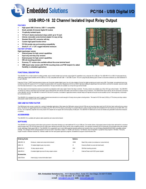
USB-IIRO-16 32 Channel Isolated Input Relay OutputFEATURES• High-speed USB 2.0 device, USB 1.1 compatible• Small, portable 32-channel digital I/O module• 16 optically isolated inputs• 16 Form C electro-mechanical relays switch up to 1A each• Internal, removable screw terminal adaptor for easy wiring• Standard 50-pin IDC connector with key• Custom high-speed function driver• PC/104 module size and mounting compatibility• Small (4" x 4" x 1.25") rugged industrial enclosureFACTORY OPTIONSEight input/output version• External power for high current capabilities• Input only and relay only versions• External power for high current capabilities• DIN rail mounting provision• Economy "E" version also available without the screw terminal board• OEM (board only) version with PC/104 mounting holes and PCB footprint for addedflexibility in embedded applicationsFUNCTIONAL DESCRIPTIONThe USB-IIRO-16 is an ideal solution for adding portable, easy-to-install isolated input and relay output digital I/O capabilities to any computer with a USB port. The USB-IIRO-16 is a USB 2.0 high-speed device, offering the highest speed available with the USB bus. It is fully compatible with both USB 1.1 and USB 2.0 ports. The unit is plug-and-play allowing quick connect or disconnect whenever you need additional I/O on your USB port.Featuring 16 Form C (SPDT) electromechanical relays and 16 optically isolated digital inputs, the unit is the smallest of its kind for digital monitoring and control using USB. The isolated, non-polarized inputs may be driven by either DC sources of 3-31 V (or higher by special order) or AC sources at frequencies of 40 Hz to 10KHZ. Optically isolating the digital inputs from each other, and from the computer, assures smooth, error-free data transmission in noisy, real-world environments. The input channels are available via a 34-pin IDC type vertical header.The relay outputs are de-energized at power-up to prevent an unintended control output signal. Data to the relays is latched. The relay contacts are available via a 50-pin IDC type vertical header. The USB-IIRO-16 contains an internal, removable screw termination board (USB-STB-84) with onboard removable screw terminals to simplify wiring connections. The USB-STB-84 mounts directly into the vertical IDC connectors of the USB-IIRO-16 PCB. The USB-IIRO-16, like the PC/104 and PCI versions, is excellent in applications where on-board relays are required and inputs must be isolated such as in test equipment, instrumenta-tion, and process control.The USB-IIRO-16 is designed to be used in rugged industrial environments but is small enough to fit nicely onto any desk or testing station. The board is PC/104 sized (3.550 by 3.775 inches) and ships inside a steel powder-coated enclosure with an anti-skid bottom.OEM USB/104 FORM FACTORThe OEM (board only) version is perfect for a variety of embedded applications. What makes the OEM option unique is that its PCB size and mounting holes match the PC/104 form factor (without the bus connec-tions). This allows our rugged digital board to be added to any PCI-104 or PC/104 stack by connecting it to a simple USB port usually included on-board with embedded CPU form factors such as EBX, EPIC, and PC/104. This is especially important since many newer CPU chipsets do not support ISA and have plenty of USB ports. The USB-IIRO-16 OEM board can also be installed using standoffs inside other enclosures or systems.ACCESSORIESThe USB-IIRO-16 is available with optional cable assemblies and screw terminal board.SOFTWAREThe USB-IIRO-16 is plug-and-play which allows quick connect or disconnect whenever you need additional I/O on your USB port. The module utilizes a high-speed custom function driver optimized for a maximum data throughput that is 50-100 times faster than the USB human interface device (HID) driver used by many competing products. This approach maximizes the full functionality of the hardware along with capitaliz-ing the advantage of high-speed USB 2.0. The USB-IIRO-16 is supported for use in most USB supported operating systems and includes a free Linux and Windows 98se/Me/2000/XP/2003 compatible software package. This package contains sample programs and source code in Visual Basic, Delphi, C++ Builder, and Visual C++ for Windows. Also incorporated is a graphical setup program in Windows. Third party support includes a Windows standard DLL interface usable from the most popular application programs. Embedded OS support include Windows XPe.Ordering Guide OptionsUSB-IIRO-16Enclosure, module and screw terminal board -OEM Board Only version (no enclosure or screw terminal)USB-II-1616 isolated digital inputs only version -E Economy Model (no screw terminal board)USB-RO-1616 relay outputs version -DIN DIN Rail mounting provisionUSB-IIRO-88 isolated digital inputs and 8 relay outputs version -P External Power and AC/DC power adapterAccessoriesUSB-STB-84 Internal plug in screw termination boardBlock Diagram Isolated InputsNumber:Sixteen (16) Type:Non-polarized, optically isolated from each other and from computer (CMOS compatible) Voltage:3 to 31 DC or AC RMS (40 to 1000 Hz)Isolation:500V* (see manual) channel-to-ground and channel-to-channel Resistance:1.8K ohms in series with opto-coupler Filter Response:Rise Time = 4.7 mS / Fall Time = 4.7 mS Non-filter Response: Rise Time = 10 uS / Fall Time = 30 uS SpecificationsBus Type: USB 2.0 Hi-speed, USB 1.1 Full-speed compatible Relay OutputsNumber:Sixteen (16) SPDT Form C Contact Type:Single crossbar; Ag with Au clad AC Load:0.5 A at 125 VAC (62.5 VA max.)DC Load:1A at 24 VDC (30 W max.)Switching Voltage:125 VAC, 60 VDC (max.) Switching Current:1A (max.) Contact Resistance:100 mOHM (max.)Contact Life (Mechanical):5 million operations (min.)Operating Time:5 msec (max.)Release Time 5 msec (max.)EnvironmentalOperating Temperature Range0º to +70º C Storage Temperature Range-40º To +85º C Humidity:Maximum 90% RH, non-condensing Board Dimension:3.550 x 3.775 inches.Box Dimension:4.00 x 4.00 x 1.4 inches.Power+5VDC provided via USB bus up to 500mA**5V @ 30mA, typical (all relays OFF, add 30mA per turned on relay)5V @ 510mA, typical (all relays ON)** Optional on-board external power circuitry and AC/DC adapter can be ordered (“-P” option) if current use is expected to be greater than what can be supplied by the USB bus. Please check to see how much current your USB port can supply and how much current you anticipate using.。
洛雷克16通道彩色多路复用器说明书

Manual De InstrucciónINTRODUCCIÓNFelicitaciones en su compra del multiplexor de color de 16 canales de Lorex. El mulitplexor de 16 canales facilita un sistema avanzado de la seguridad en cualquier monitor auxiliar. Conecte hasta16 cámaras conel multiplexor y opinión las16 localizaciones simultáneamente. Siete diversos modos de exhibición están disponibles, ofreciendo una variedad amplia de opciones de visualización.Cuando se estáutilizado conjuntamente con una grabador de seguridad profesional( tal como un VCR del lapso de tiempo o un DVR), el multiplexor de 16 canales registra simultáneamente cada cámara enPantalla Compelta, permitiendo al usuario a reproducir las grabaciones en Pantalla Completa o Pantalla Dividida. La detección Pixel-basada en movimiento también se incluye.Para aprender más sobre este sistema o para descubrir más sobre otris productos disponibles, visite porfavor nuestro Web site en CARACTERÍSTICAS16 Características Del Multiplexor Del Color Del Canal•Multiplexación Completa Del Duplex: 16 cámaras pueden grabar/ reproducir/ despliega de video en vivo al mismo tiempo•La función de multiplexación soporta de 4 a 16 canales•Opciones de Visualización: 7 diversos modos de exhibición incluyendo: Pantalla completa, cuadrángulo,7 can, 9 can, 10 can, 13 can, 16 can•Los modos de exhibición son seleccionables durante la reproducción del video en vivo o la visualización •Exhibición de la pantalla y la función del reloj en tiempo real•Cuadro en el cuadro, aumento digital 2x•Detección Digital pixel-basada en movimiento•Cuadro ajustable por el canal•16 entradas de alarma, una salida de alarma•Alarma de pérdida de video•Almacenamiento de la memoria de hasta50 acontecimientos•Control externo del anfitrión RS-232/485NOTA:El multiplexor de 16 canales se utiliza normalmente en conjunto con un grabador de seguridad, tal como un VCR del lapso de tiempo o un DVR. Para la instrucción en la conexión a un VCR / aun DVR, refierase por favor a los diagramas en los apéndicesADVERTENCIA DE SECURIDADTodas las instrucciones de seguridad y de funcionamiento deben ser leídas antes de que se utilice el equipo. La operación incorrecta puede causar daño irremediable al equipo.•Por favor levante y coloque este equipo suavemente.•No exponga este equipo debajo de la luz del sol directa.•No utilice este equipo cerca del agua o en contacto con agua.•No derrame líquido de cualquier clase encima del equipo.•No desenchufe el conectador de energía antes de apagar la energía correctamente.•Este equipo se debe funcionar usando solamente la fuente de energía del paquete estándar.•Reparaciones o repuestos no autorizados pueden resultar en fuego, descarga eléctrica u otros peligros.•No encienda ni apague la energía dentro de un período de tiempo corto(en el plazo de 3 segundos).•No intente darle servicio a este equipo. Refiera todos los trabajos de servicio al personal de servicio calificado.•Esta unidad se debe utilizar solamente con el tipo de fuente de energía indicada en la etiqueta del fabricante.•Esta instalación debe conformarse con todos los códigos locales.PRECAUCIÓN!RIESGO DE DESCARGA ELÉECTRICA.NO ABRIRPRECAUCIÓN! PARA REDUCIR EL RIESGO DE DESCARGA ELÉCTRICA.NO RETIRE LA CUBIERTA (NI EL RESPALDO). EN EL INTERIOR NO HAYPIEZAS QUE PUEDAN SER MANTENIDAS POR EL USUARIO. ENCARGUEEL MANTENIMIENTO A PERSONAL CALIFICADO DE SERVICIO.Explicación de dos símbolosEl símbolo del rayo con punta de flecha, dentro de un triángulo equilátero,es para alertar al usuario sobre la presencia de “voltage peligroso" no aisladodentro del gabinete del producto que puede ser de suficiente magnitud paraconstituir un riesgo de descarga eléctrica a la personas.El punto de admiración dentro de un triángulo equilátero tiene laintención de alertar al usuario acerca de importantes instrucciones de!operación y mantenimiento(servicio) en la documentación queacompaña al artefacto.CONTENIDO PAGINA1. El SISTEMA INCLUYE ----------------------------------------------------------------------------2. CONTROLES DEL PANEL DELANTERO ----------------------------------------------------3. INDICADORES DE LED --------------------------------------------------------------------------4. CONTROLES DE MENÚ-------------------------------------------------------------------------5. OPCIONES DEL MENÚ--------------------------------------------------------------------------6. CHANNEL SETUP MENÚ-----------------------------------------------------------------------7. PANEL TRASERO ---------------------------------------------------------------------------------8. AUTO SECUENCIA -------------------------------------------------------------------------------9. ALARMAS Y PERDIDA DE VIDEO ------------------------------------------------------------10. PROTOCOLO DEL TELECONTROL RS232 ------------------------------------------------11. DETECCIÓN DE MOVIMIENTO ---------------------------------------------------------------12. SOLUCIONES A PROBLEMAS ----------------------------------------------------------------13. ESPECIFICACIONES TÉCNICAS ------------------------------------------------------------14. ACCESORIOS OPCIONALES -----------------------------------------------------------------15. APÉNDICE #1 –CONFIGURACIÓN TÍPICA -----------------------------------------------16. APÉNDICE #2 –CONEXIÓN A UN SENSOR DE MOVIMIENTO PIR --------------17. APÉNDICE #3 –CONEXIÓN A un VCR Del LAPSO De TIEMPO De LOREXPARA La GRABACIÓN Y La SINCRONIZACIÓN De LaALARMA -----------------------------------------------------------------------18. APÉNDICE #4 –CONFIGURACIONES DE LOS PINES PARALA CONEXIÓN TO PC ----------------------------------------------------19. APÉNDICE #5 –CARTA DE REGISTRO DE LA TARIFA -------------------------------4466789101011121313141516171819Fuente de Poder Multiplexor a Colores de 16 CanalesMENÚ DE CONTROLES DEL PANEL DELANTERO MENU LIVELine MotionESC :EL VCR [ ]VCR o DVR del lapsoZOOM [ ] /MODO DE EXHIBICIÓN DE 16 CANALES [ ] / ▲a) Presionando este botón lo dirige a un modo de exhibición de 16 canales.b) Este botón también sirve como flecha ascendente en la navegación del menú, mueve el cuadro secundario para arriba en modo de PIP, y explora hacia arriba en modo de zoom. SELECCIONAN EXHIBICIÓN MODO [ ] / ▼a) Presionando este botón permite que usted seleccione entre seis diversos modos de visualización en la pantalla (4 can / 7 can / 9 can / 10 can / 13 can / 16 can). Después de presionar este botón, presione un botón válido del canal (a partir de la 4-16, correspondiendo a las seis opciones arriba) para seleccionar el modo de la visualización.Por ejemplo, si usted desea visualizar un despliegue de 7 canales, presione el botón del canal 7.b) Este botón también sirve como la flecha que va hacia abajo en la navegación del menú, mueve el cuadro secundario abajo en modo de PIP, y explora hacia abajo en modo del zumbido.9.10.INDICADORES DE LEDEn cada botón estáun indicador rojo del LED, que demuestra el estado de sistema y ayuda a navegar en modo del menú.Por ejemplo, cuando en modo de PIP los indicadores siguientes del LED se encienden por las razones siguientes: Botón dePIP –muestra que usted estáen modo de PIPCuatro botones con flechas –muestra que moviendo la subpantalla hacia los botones con flechas es posible Botón del VCR –demostraciones en las que usted puede intercambiar las pantallas para visualizar el aparato delectura del VCR en modo PIPBotón LIVE –muestra que usted intercambiar las pantallas para visualizar otros canales en modo de PIP Botón deESC –muestra que usted puede salir de la PIP presionando este botón.Cuando en la duda con respecto a los botones son los correctos a presionar, los indicadores del LED son una referencia provechosa pues demuestran quéllaves son aplicables en ciertas situaciones.CONTROLES DE MENÚPresionando ENTER y ESC simultáneamente para que salga la pantalla del menu. Se contornean abajo los botones usados para la navegación al usar el menú. ▲y ▼: Busque hacia arriba y abajo enter las opciones del menú.◄ y ►: Busque de lado a lado entre una opción que se ha seleccionado.Hace selecciones cuando hay una opción entre 2 opciones (por ejemplo: ON o OFF).: Lo dirige a la pantalla de configuración del canal desde el MenúPrincipal.Aumenta un valor alfanumérico de una opción del menu cuando se eata editando (cuando estáparpadeando).: Regresa al MenúPrincipal desde la pantalla de la Configuración del Canal.Disminuye un valor alfanumérico de una opción del menúal corregirlo (cuando estáparpadeando).ENTER:Selecciona un submenú/ una opción en un submenúpara búsqueda / modificación.ESC: Completa la modificación de una opción del menú; sale de un menú.[ y ] de la alarmaLOOP (Canales 1-16)Permite la conexión a otros dispositivos video, transmitiendo una salida de la entrada video en el canal respectivo.ENTRADA VIDEO (Canals 1-16)16 entradas de la cámara de vídeo de BNC, para los canales 1-16. Conecte hasta 16 cámaras con estas entradas (conectores de BNC requeridos).SALIDA AL VCRUse con un cable de video (no provisto) para transmitir el vídeo del multiplexor a un VCR o a un DVR.ENTRADA AL VCRRecibe el vídeo de un VCR o de un DVR.SALIDA DEL MONITORTransmite el vídeo a un monitor auxiliar (una TV o monitor de seguridad).LLAMADATransmite el vídeo a un segundo monitor. El monitor de Llamada despliega los 16 canales en Auto Secuencia.Durante una alarma, el monitor de Llamada despliega la Pantalla Compelta del canal en donde estáocurriendo la alarma.Si dos canales tienen alarmas simultáneamente, el monitor de Llamada desplegaráesos dos canales en Secuencia en la visualización de la Pantalla Compelta.SALIDA DEL SVHSConecte este puerto de salida con la entrada de SVHS de un VCR (si estádisponible). ENTRADA DEL SVHSConecte este puerto de entrada con la salida de SVHS de un VCR (si estádisponible).ENTRADA DE ENERGÍAConecta con el adaptador de la energía de la C.C. 12V.INTERRUPTOREste interruptor controla la energía a la unidad. Presione el lado con “I” para ENCENDERLO, o el lado con “O” para APAGARLO.RS232 / ENTRADA DE LA ALARMA / EXTERNAL I/OSe conecte con un Bloque de la Alarmar, que acomoda la conexión del sensor de movimiento de PIR y activa las Alarmas Externas. Alternativomente, esta salida puede servir como Protocolo Remoto para el control vía una PC. Refiera por favor a los apéndices #2-4 para los diagramas de las conexiones del bloque del alarmar. GND –la conexión de tierra del bloque de la alarma.1.2.3.4.5.6.7.8.9.1011.12.PANEL TRASEROel iconoel iconoPROTOCOLO DEL RS232 REMOTO La entrada de RS232 de la alarma permite que usted controle el sistema del multiplexor de su PC. Para alcanzar esto, usted requeriráun programa portuario de la comunicación de COM RS232 instalado en su PC. Hay muchos de estos programas del software disponibles en el Internet, algo de el cual estálibre.La conexión remota en el multiplexor utiliza8 bits de datos, 1 bit de inicio, y 1 bit de parada. Debajo estáun ejemplo de la secuencia de datos con los códigos de control demostradosACT –OxFF OxCO ID FUNCTION STOP –Ox7F El teclado de la PC simula el teclado numérico del procesador del cuadrángulo. Por ejemplo, presionar“z”haráque el multiplexor va a enfocar modo. Observe que las letras son caso sensible. Debajo estáuna lista de llaves correspondientes, y sus códigos.FUNCIÓN CÓDIGO LLAVE FUNCIÓN CÓDIGO LLAVE MENÚ0x4D M140x45EESC0x1B ESC150x46F CONGELAR0x5A Z160x47G EN VIVO0x49I ENTER+FREEZE0x48HVCR0x56V ENTER+LIVE0x4A J ZUMBIDO0x7A z ENTER+VCR0x4F O PIP0x50P ENTER0x0D ENTER IZQUIERDO0x4C L SECUENCIA 10x61a DERECHA0x52R SECUENCIA 20x62b ARRIBA0x55U SECUENCIA 30x63c ABAJO0x4E N SECUENCIA 40x64d KEY_LOCK0x4B K SECUENCIA 50x65e 10x311SECUENCIA 60x66f20x322SECUENCIA 70x67g30x333SECUENCIA 80x68h40x344SECUENCIA 90x69i50x355SECUENCIA 100x6A j60x366SECUENCIA 110x6B k70x377SECUENCIA 120x6C l80x388SECUENCIA 130x6D m90x399SECUENCIA 140x6E n100x41A SECUENCIA 150x6F o110x42B SECUENCIA 150x6F o120x43C SECUENCIA 160x70p130x44Dde la [ = ON / = OFF ] del cursor ON o OFF. Puesto que•Usted puede que note que una pantalla azul aparezca brevemente a medida que usted navegue entre los modos de visualización. Esto es normal -espere simplemente 2 segundos para que la pantalla azul desaparezca.Pantalla Azules•Fije la Polaridad de la Alarma según si su sensor de movimiento PIR es Normalemente Abierto o Normalmente Cerrado.•Si no se conectan ningunos sensores de movimiento, APAGUE la Polaridad de la Alarma.Alarma Continuo•Compruebe las conexiones del cable de fuente de energía•Compruebe que haya energía en el enchufeNinguna Energía•Si usted estáutilizando una TV como monitor auxiliar, usted va a necesitar fijar el canal como AUX.(o referido a veces como “TV / Video”).•Compruebe por favor si el cableado entre el monitor y Multplexer estácorrecto.•Verifique que las cámaras estén recibiendo energía Incapaz de visualizar cámarasREMEDIOPROBLEMALOCALIZACIÓN DE AVERÍASESPECIFICACIONES TÉCNICASDebido a que nuestros productos están sujetos a mejoras continuas, SVC se reserva el derecho de modificar el diseño y especificaciones del producto sin aviso previo y sin incurrir en ninguna obligación. S.E. u O.Entrada de la Cámara fotográfica 16 Canal BNC Entrada del VCR1 BNC, 1 S-VIDEO Parte posteriora Del Loop de la cámara 16 Canal BNCSalida Principal Del Monitor 1 Vp-p 75 Ohms, BNC Salida Del Monitor De llamada 1 Vp-p 75 Ohms, BNC Salida del VCR1 BNC, 1 S-VIDEOArea de Detección de Movimiento15 x 12 blancos por la cámara (NTSC)Sensibilidad de Detección de Movimiento 256 niveles Detección de Pérdida de video SíCongelamiento de Imagen SíRestaurar Rango 30 marcos por el Sec.Rango De Grabación 15 cuadros por el Sec.Resolución704(H)x468(V) full screen Prioridad Dinámica De la Grabación Sí(Programable)Tiempo De Detención Programable (1~10 Sec)Cuadro en cuadro Sí(Mueble)Key LockSíAumento de la Imagen 2 x 2 (mueble)Título De la Cámara 6Ajustes videoColor/Contraste/Brillo ajustable por el canal Entrada de la Alarma Entrada de la TTL, hi (5V), bajo (GND)Salida de la Alarma COM, N.O.Historia de la Alarma 50 acontecientos Control RemotoRS232 or RS485Salida Del Disparador del VCR Sí(TTL hecha salir)Formato de Hora YY/MM/DD, DD/MM/YY, MM/DD/YY, OFF Fuente de PoderDC12V, 1.25ARS-232C / RS-485 (bps)115200/57600/19200/9600/4800/3600/2400/1200Dimensiones 432 (W) x 76(H) x 311(D)Peso5,200gGraba imágenes digitales enAccesorio de visión nocturnaGira la cámara hasta270°Nota : Si esta usando una TV como monitor auxiliar, puede tener que ser fijado en el modo AUX. (designado a veces como TV / Video)APÉNDICE #1 –CONFIGURACIÓN TÍPICA16Video Camera . (2)VCRCall MonitorRecordPlay1Main MonitorGNDVCRPCRS232Alarm InputSensorAlarm USTED PUEDE TAMBIÉN CONECTAR DOS MONITORES USANDO LA CONFIGURACIÓN DEMOSTRADA ABAJO:EL MULTIPLEXOR DE 16 CANALES TIENE DE BNC QUE SE CONECTAN CON OTRAS FUENTES DE VIDEO. LOS CABLES DEL ACOPLADOR DE BNC Y VIDEO ESTAN INCLUIDOS.PCAlarm InputVCR.Video Camera (16)....12Record PlayGNDMain MonitorRS232SensorAlarmde de10114APÉNDICE #4 –CONFIGURACIONES DE LOS PINES PARA LA CONEXIÓN A LA PC PUERTO COMDE 25 PINESPUERTO COMDE 9 PINESAPÉNDICE #5 –CARTA DE REGISTRO DE LA TARIFA002H ~ 15.000~ 3.750~ 0.938006H ~ 10.000~ 2.500~ 0.625 008H ~ 7.500~ 1.875~ 0.469 012H ~ 5.000~ 1.250~ 0.313015H ~ 4.000~ 1.000~ 0.250016H ~ 3.750~ 0.938~ 0.235018H ~ 3.333 ~ 0.833~ 0.208020H ~ 3.000 ~ 0.750~ 0.188024H ~ 2.500 ~ 0.625~ 0.156036H ~ 1.667 ~ 0.417~ 0.104040H ~ 1.500~ 0.375~ 0.094048H ~ 1.250 ~ 0.313~ 0.078060H ~ 1.000 ~ 0.250~ 0.063072H ~ 0.833 ~ 0.208~ 0.052080H ~ 0.750 ~ 0.188~ 0.047084H ~ 0.667 ~ 0.167~ 0.042120H ~ 0.500 ~ 0.125~ 0.031160H ~ 0.375 ~ 0.094~ 0.024168H ~ 0.333 ~ 0.083~ 0.021240H ~ 0.250 ~ 0.063~ 0.016360H ~ 0.167 ~ 0.042~ 0.011480H ~ 0.125 ~ 0.031~ 0.008720H ~ 0.083~ 0.021~ 0.005960H~ 0.063~ 0.013~ 0.003Modo deGrabación CANAL 1 (Imagen/segundo)CANAL 4 (Imagen/segundo)CANAL 16 (Imagen/segundo)。
ECOM串口助手V2.60使用说明书
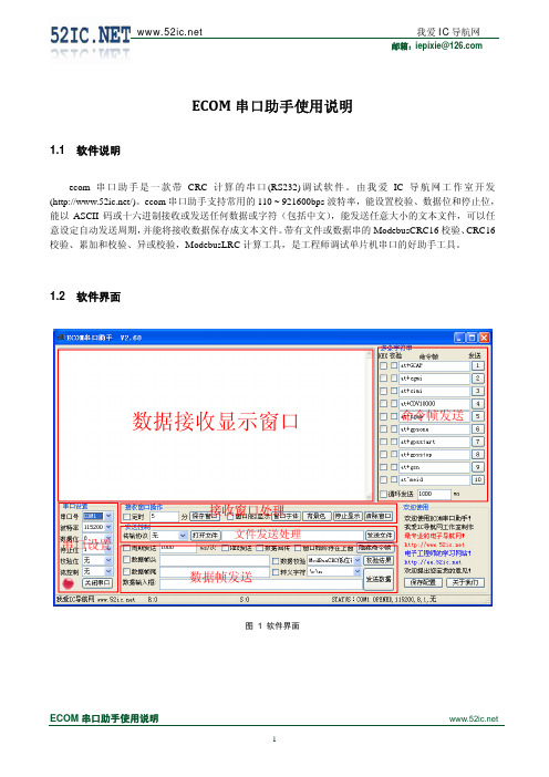
我爱 IC 导航网
邮箱:iepixie@
1.4.7 文件及数据校验 1. 文件校验
Ecom 串口软件带有计算文件 ModebusCRC16 校验、 CRC16 校验、 累加和校验、 异或校验, ModebusLRC 的计算工具,计算方法是在“传输协议”打开文件对话框中打开待计算的文件,选择“数据校验格式” ,点 击“校验结果”按钮,对话框中将显示计算结果,如果需要保存结果,点击“保存窗口”按钮即可。
1.
ModebusCRC16 校验算法
//********************************************************************************************************** //* 函数名称 : GetModbusCRC16 //* 函数功能 : ModbusCRC16 校验 //* 入口参数 : cp //* //* 备 注 : 要检验的字符 leng 长度
ECOM 串口助手使用说明
5
我爱 IC 导航网
邮箱:iepixie@
DATAHEAD3=AA AA TAIL3=1 DATATAIL3=BB BB DATA3=01 02 03 04 05 06 07 08 09 0A 0B 0C 0D 0E 0F 10 12 13 14 15 16 17 18 19 DELAY3=1000 [END]
[] ;发送命令条的起始条数 start_52ic=0 ;命令条总数,不要写错了,否则会出错,最大 100 条。 total_52ic=4 ;循环多少次后退出。最大 100 次循环。 cycle_52ic=5 ;检验方式。 check_52ic=4 [Sending] ;发送对话框是否 HEX 格式发送 HEX0=0 ;包尾是否加校验 CHECK0=1 ;是否使用转义符 TAILED0=0 ;数据头是否选择 HEAD0=0
16路开关量采集模块使用说明书
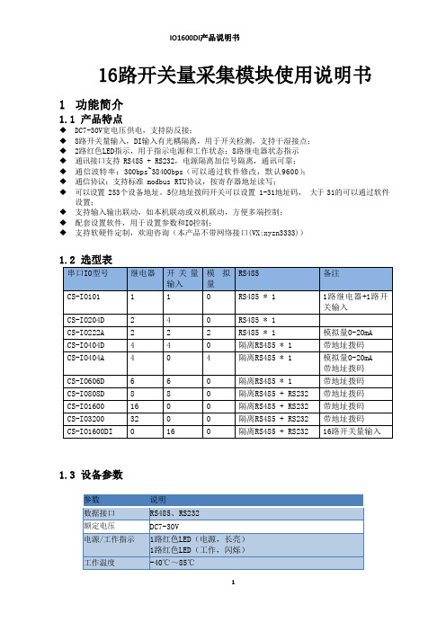
16路开关量采集模块使用说明书1功能简介1.1产品特点◆DC7-30V宽电压供电,支持防反接;◆8路开关量输入,DI输入有光耦隔离,用于开关检测,支持干湿接点;◆2路红色LED指示,用于指示电源和工作状态;8路继电器状态指示◆通讯接口支持 RS485 + RS232,电源隔离加信号隔离,通讯可靠;◆通信波特率:300bps~38400bps(可以通过软件修改,默认9600);◆通信协议:支持标准 modbus RTU协议,按寄存器地址读写;◆可以设置 253个设备地址。
5位地址拨码开关可以设置 1-31地址码,大于 31的可以通过软件设置;◆支持输入输出联动,如本机联动或双机联动,方便多端控制;◆配套设置软件,用于设置参数和IO控制;◆支持软硬件定制,欢迎咨询(本产品不带网络接口(VX:xyzn3333))1.2选型表1.3设备参数2产品图片2.1通讯接线本产品默认地址为1,拨码开关出厂均在off状态。
上位机软件可以使用默认地址1来跟设备通讯(或者广播地址254,仅适用网内挂载一台设备的情况)。
2.1.1RS485接线2.1.2RS232接线2.2开关量输入接线开关量输入接口兼容干湿节点,请注意有源信号和无源信号的不同接法。
开关量采集端子的内部光耦电路如下,V-(DGND)为光耦负公共端,传感器信号分别接V+(VIN) 和Inx即可。
2.2.1有源信号接线示意图适用测量带电压的信号,如电平高低,脉冲输出。
2.2.2无源开关量(干接点)接线适用于采集无源触点信号,如开关,按键。
3参数及工作模式配置3.1设备地址3.1.1设备地址的介绍本设备的软件地址默认为 1,使用广播地址为 254 也可进行通讯,用0无法通讯。
注意:没有拨码开关的设备,通讯地址 = 软件地址。
拨码开关地址表通讯地址 = 硬件地址(拨码开关地址) + 软件地址。
出厂设备使用通讯地址1即可通讯。
3.1.2设备通讯地址的读取设备正常链接后,然后点击串口继电器配套调试软件上方“读取地址”,即可读到设备的当前地址【仅支持总线上存在一台设备时,进行广播读取地址】。
诺控通讯teri优质设备联网服务器用户手册M0802 V1.4
目录第一章系统简介 (3)1.1概述 (3)1.2功能特点 (3)1.3规范与标准 (4)第二章硬件安装 (6)2.1 设备结构 (6)2.2 设备安装 (7)2.2.1 连接电源 (7)2.2.2 连接网络 (7)2.2.3 连接串口设备 (8)2.2.4 指示灯说明 (9)2.2.5 设备启动及Reset复位开关的使用 (10)第三章设备配置和管理 (10)3.1 设备管理方式 (10)3.1.1 Web浏览器管理方式 (10)3.1.2 Telnet管理方式 (12)3.1.3 Console控制台管理方式 (14)3.2 设备参数设置 (16)3.2.1 设备参数结构 (16)3.2.2 设备配置 (16)第四章软件安装 (42)4.1 软件安装 (42)4.1.1 系统要求 (42)4.1.2 软件安装 (42)4.2 软件设置 (42)4.2.1 软件运行、设置 (42)4.2.2 固件程序升级 (43)第五章故障排除 (45)5.1 常见故障排除 (45)附件: (45)A. 接口线序 (45)B. Modbus功能码、地址、数据类型: (47)第一章系统简介1.1概述M0802串口、I/O设备联网服务器(简称:M0802)是我司自主研发的RS-232/485/422串口、Digital Input/Output接口设备联网产品。
M0802系列产品采用32位处理器,结合高效的嵌入式系统,使设备运行更加安全、稳定。
M0802系列串口、I/O联网服务器产品让用户无需投入大量资金来进行更换或升级,就可以使原有的RS-232/485/422串口、开关量工业控制设备立即具备网络互联能力,为串口数据信息提供高效、安全、稳定的数据通道。
M0802系列产品被广泛应用于通信、控制领域,如电力监控、机房监控、PLC、智能电表、煤气表、生物识别装置、读卡机等环境,是连接串口设备及TCP/IP以太网络的桥梁。
16-Port Console Server 产品说明说明书
16-Port Console Server with USB - Built-In Modem, Dual GbE NIC, 16 Gb Flash, 1U Rack, TAAMODEL NUMBER:B096-01616-port console server lets you remotely access and control serial-based networking equipment through one highly secure gateway.FeaturesAccess All Your Serial and Network Devices from Anywhere in the World at Any Time This USB console server provides secure in-band (primary network) and out-of-band (alternate channel) remote access to serial- and network-connected routers, network switches, firewalls, PBX systems, UPS systems, PDUs and other devices. It offers reliable network connectivity with dual Gigabit primary and failover Ethernet ports (the second port can also be used as a gateway port) and dual power supplies. You can use the B096-016 in a wide variety of locations, including wiring closets, branch offices, kiosks, point-of-sale and other remote sites where a quick identification and resolution of network issues is imperative.Simple and Flexible Accessibility The 16 RJ45 ports are configured to use standard Cat5e/6 patch cable when connecting to Cisco devices. They integrate with industry-standard directory servers using TACACS+, RADIUS, LDAP and Kerberos authentication. 16 Gb of internal NAND flash memory can be used for log storage and file storage.Built-In V.92 Modem for Out-of-Band Access A serial data/fax modem enables 3G cellular out-of-band (alternate channel) access when remote sites experience a network outage. You can dial into the rack console from anywhere at any time, eliminating the costly need for additional USB modems that can be accidentally disconnected or have compatibility issues. However, if desired, you may connect one of the RJ45 ports to an external Multitech MT9234MU-CDC-XR or US Robotics USR5637 USB modem (not included) to receive out-of-band access.Router/Gateway Each gateway can port forward to an unlimited number of locally networked hosts (computers, routers). This rack console also includes a built-in stateful firewall and embedded DHCP server to host a separate management LAN for critical traffic.The Utmost in Security to Keep Your Sensitive Data Private This 16-port console server supports the following security features and standards: FIPS 140-2, SSL and SSH, stateful firewall, OpenVPN and IPSec VPN. The embedded FIPS 140-2 OpenSSL cryptographic module is validated to meet FIPS 140-2 standards and has received Certificate #1051.PowerMan PDU and UPS Support This IP terminal server uses PowerMan for PDU and RPC HighlightsManage routers, UPS systemsand other serial-basedequipment from anywhere 24/7 qValidated to meet FIPS 140-2standards to ensure utmostprotection of private dataqDual 10/100 Ethernet ports forprimary network connection and automatic failoverqAdvanced authentication withLDAP, RADIUS, TACACS+ and Kerberos serversqUSB ports connect to PDUs and UPS systems with remotemanagement abilitiesqApplicationsSecurely access and controlservers, routers, KVM switchesand other serial-connecteddevices in your data center 24/7 qManage diverse server anddevice platforms using anetwork connectionqDiagnose and fix issues withyour IT infrastructure remotelywith little or no downtimeqTroubleshoot equipment issueswithout spending time/moneytraveling to remote locationsqPackage IncludesB096-016 16-Port Serial Serverwith USBq(2) Cat5 patch cables, 6 ft.qDB9 to RJ45 straight connector qDB9 to RJ45 crossoverconnectorq(2) C13 to NEMA 5-15P powercords, 6 ft.qRack-mounting hardwareqCD with owner’s manualqQuick Start GuideqSpecificationsmanagement and Network UPS Tools for UPS system monitoring and management. It provides support for Tripp Lite and other power products, so you can remotely manage power to your connected equipment.USB Ports Two USB 2.0 ports and one USB 1.0 port allow connection to newer devices with USB ports,such as Tripp Lite’s wide variety of PDUs and UPS systems with WEBCARDLX or other LX Platform remote management cards.Compact Design for Convenient Mounting The heavy-duty steel housing comes with mounting brackets for 1U installation in an EIA-standard 19-inch rack.TAA-Compliant for GSA Schedule Purchases The B096-016 is compliant with the Federal TradeAgreements Act (TAA), which makes it eligible for GSA (General Services Administration) Schedule and other federal procurement contracts.© 2023 Eaton. All Rights Reserved. Eaton is a registered trademark. All other trademarks are the property of their respective owners.。
串口控制管理服务器的使用CCM-16[仅供借鉴]
![串口控制管理服务器的使用CCM-16[仅供借鉴]](https://img.taocdn.com/s3/m/72d7eaa684254b35effd3455.png)
特选课件
55
在学生机上的配置 安装软件
特选课件
56
在学生机上的配置
启动COM port 软件
特选课件
57
在学生机上的配置
把192.168.1.10这个 设备(CCM)的1号 端口,(虚拟)设置 为本PC的COM8口;
特选课件
35
网络设备
RJ45口 Console口
10M/100M 以太网口
CCM
192.168.1.10/24
192.168.1.11~ 192.168.1.18
特选课件
交换机
36
特选课件
37
CCM的配置
特选课件
返回
38
CCM的配置
1. 登录CCM
2. TCP Port 工作模式
(超级终端)
特选课件7Fra bibliotek4.4.1 通过console口管理交换机 DB-25串口
特选课件
DB-9串口
8
4.4.1 通过console口管理交换机
console线
无论交换机的console口是采用串行接口,还是 采用RJ-45接口,都需要通过专门的Console线 连接至计算机的串行口,然后进行配置。
通过console口管理交换机的方式,属于CLI方式。 CLI(command-line interface,命令行界面)
特选课件
17
4.4.1 通过console口管理交换机
交换机的命令行工作模式
特选课件
18
4.4.1 通过console口管理交换机
16路串口服务器NB1A1产品基本功能详解
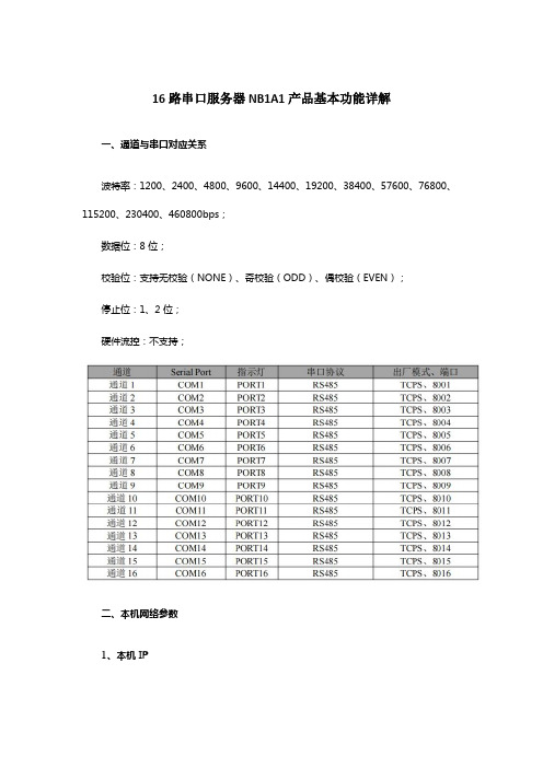
16路串口服务器NB1A1产品基本功能详解一、通道与串口对应关系波特率:1200、2400、4800、9600、14400、19200、38400、57600、76800、115200、230400、460800bps;数据位:8 位;校验位:支持无校验(NONE)、奇校验(ODD)、偶校验(EVEN);停止位:1、2 位;硬件流控:不支持;二、本机网络参数1、本机 IPSTATIC(静态 IP):用户可以定义配置 IP、子网掩码、默认网关、域名解析服务器(DNS 服务器);DHCP(动态 IP 获取):设备登录服务器自动获得服务器分配的 IP 地址、子网掩码、网关地址、DNS 服务器地址参数并配置使用;2、DNS(域名解析)用户输入域名的时候,会自动查询 DNS 服务器,由 DNS 服务器检索数据库,得到对应的IP 地址,在静态 IP 模式下用户可自定义域名解析的服务器,用于解析私有域名服务器数据,动态 IP 模式下设备自动跟随路由设备配置的域名解析服务器,用户只需修改路由设备的 DNS服务器即可,无需配置本设备。
3、断网重连周期设备检测到与服务器断开连接时周期发起重连请求,因此“断线重连时间”并不会影响正常情况下的连接建立时间,用户可自定义配置请求周期,默认5s。
4、超时重启(无数据重启)设备监控数据收发情况,若长时间设备未进行数据收发,设备自动执行重启,以保证长时间工作的稳定性。
该功能默认开启周期为30分钟,用户可自定义开启或关闭超时重启也可自定义无数据重启的周期。
三、硬件恢复出厂设备的Reload引脚,持续按下5-10s秒后松开,除NET外其余LED亮起,设备重启,重启后设备恢复出厂完成。
四、设备工作模式1、TCP ServerTCP Server即TCP服务器。
在TCP Server模式下,设备监听本机端口,接受客户端的连接请求并建立连接进行数据通信。
在关闭Modbus网关功能时,设备将串口接收到的数据发送给所有与设备建立连接的客户端设备。
串口服务器用户手册

深圳市天地华杰科技有限公司串口服务器用户手册RS-232/485/422 —TCP/IP深圳市天地华杰科技有限公司深圳市天地华杰科技有限公司目录1产品简介 (1)1.1产品特色 (1)1.2技术规格 (1)1.3外部接口 (2)1.4安装 (3)2使用指南 (4)2.1串口服务器配置 (4)2.2通讯测试 (7)2.2.1单机测试 (7)2.2.2运行测试 (10)串口服务器用户手册1产品简介1.1产品特色串口服务器是RS232/485/422串口到以太网TCP/IP协议的双向转换传输设备,变传统的串口通讯为网络通讯,实现串口设备的快速联网。
转换器采用透明传输的方式,用户不用知道复杂的TCP/IP协议,不用更改程序即可实现原有串口设备的网络连接,节省您宝贵的时间和已有投资。
其极低廉的价格能提升您产品的核心竞争力;简单灵活的配置和极高的可靠性能满足您任何苛刻的应用,是您理想的选择。
1.2技术规格●接口:10Base-T, RS232/485(DB9母头)●协议:TCP/UDP/IP/ICMP, Ethernet, ARP●串口:300bps – 115200bps●电源:DC 5V ± 10%●尺寸:92X64X24mm(高级铝合金屏蔽外壳)1串口服务器用户手册21.3外部接口串口服务器用户手册1.4安装串口服务器采用WINDOWS应用程序ezConfig通过网络配置参数,因此,客户计算机应安装网卡并配置好网络环境,如需连接多个串口服务器设备,则还需网络交换机或HUB。
1、如客户计算机已安装网卡并配置好网络环境,则省略本步骤。
如尚未安装网卡,则应首先安装网卡并配置IP 地址及子网掩码。
客户的机器如未与其它计算机联网,则该机器的IP地址可任意配置:一般采用保留三类IP地址,即192.168.X.Y(注:同一局域网网中X均相同,Y任意,但不能重复),子网掩码为255.255.255.0。
如该计算机已在局域网中,请遵循系统管理员的安排;2、客户方的网络环境配置完后,可通过交叉网线连接客户机网卡的接口及串口服务器上的RJ45接口,或两者都用直连网线接在网络交换机或HUB上;3、用RS232电缆将串口服务器上的串口同嵌入式设备上的串口或PC机的串口(用于测试串口服务器)连接起来;4、串口服务器接通电源后即开始工作,电源指示灯PWR 点亮,同时运行灯RUN有规律的闪烁,说明电源正确接通串口服务器工作正常。
Orion 16 E1 + 光纤多服务复用器说明书
16E1+(Wire-Speed)Optical MultiplexerGigabit Ethernet Product BrochureORION TELECOM NETWORKS INC.RIONTELECOMNETWORKSHeadquarters:Phoenix,Arizona Orion Telecom Networks Inc.E-mail:Website:Address:20100,N 51stAve,Suite B240,GlendaleAZ 85308U.S.A.Phone:+1480-816-8672Fax:+1480-816-0115**********************Regional Office:Miami,Florida Orion Telecom Networks Inc.Fax:E-mail:Website:4000Ponce de Leon Blvd.Suite 470,Coral Gables,FL 33146U.S.A.Phone:1-305-777-0419,1-305-777-0201**********************Orion’s 16E1+Gigabit Ethernet (Wire-Speed)Optical Multiplexer is a unique Gigabit multi-service optical fiber transport solution which transmits both Gigabit Ethernet (Gigabit Wire-Speed)data along with upto 16E1(TDM)channels over an optical fiber link.1+1optical fiber redundancy is also available for minimizing the possibility of transmission loss due to an optical link failure.The Gigabit (Wire-Speed)Ethernet traffic along with 16E1's are multiplexed into 1.25Gbps optical link to provide a compact,high performance,high throughput and cost effective broadband network access solution.Product OverviewFeatures!!!!!!!!!!!!!!!!!!!!!!!1U height,19-Inch standard rack-mountable chassisWire-Speed Gigabit Ethernet traffic with 16E1data are transported simultaneously Optical line bit rate 1.25Gbps1Gbps data throughput for aggregate Ethernet trafficSupports jumbo frame size (upto 2048bytes)transmissionSupports 1+1optical link protection andAPS with less then 50ms switching timeMSA compliant SFP (Small Form-Factor)based design for improved and easy serviceability.SFP based design provides the flexibility to the customer to change service distance and support different types of optical fiberMSAstandard compliant SFP (INF-8074i,ITU-T G.695and FC-PI V2.0)SupportsAutomatic Laser Shutdown (ALS)option for added safetyPerformance analysis of optical ports Optical Transmission Failure,Loss of Optical Link,Loss of Frame and Errors (E-3/E-6)E1port complies to ITU-T G.703and G.704Jitter tolerance,jitter transfer characteristic and jitter generation fully comply with ITU-T G.823and G.742recommendationsPerformance analysis of E1ports Loss of Signal and Code ViolationPerformance Analysis of GigE port -All Received Packets,All Received Bytes,Received Broadcasts,All Transmitted Packets,All Transmitted Bytes,Transmitted Broadcasts,Received Error PacketsProvides Engineering Order Wire (EOW)Remote access and management over TCP-IP Telnet and SNMP Supports SNMP V2monitoring and trapsRemote Power Down detection (RPD)alarm.Allows the local end to detect if the remote unit is unavailable due to optical link failure or due to power down Remote software ungradableAC and DC power redundancy {-48V DC (-18V to -72V),100-250VAC options available}Complies to electrostatic discharge immunity (ESD)IEC 61000-4-2level 2RoHS and EMI/EMC compliant.Supports Command Line Interface (CLI)based on RS232(COM Port)and TCP-IP (Telnet)16E1+Gigabit Ethernet! ! !!! ! !!!!! ! ! ! ! ! ! ! ! ! ! ! ! !!Gigabit(Wire Speed)data transmissionGigabit multi-service fiber optic transport solution-Transmits both E1s and Gigabit Ethernet data over an optical fiber link/or over1+1redundant optical fiber links for added protection against link failuresCompact,high performance,high throughput and cost effective broadband network access solutionSFP based design for customer convenience,flexibility to change services distance and serviceabilityOptical distance support for550m,10Kms,20Kms,40Kms and80KmsSupports remote power down detect functionEthernet data port complies to IEEE802.3,IEEE802.3u,IEEE802.ab,IEEE802.3x recommendationsEthernet data port supports auto-negotiation function and can work in10M full/half duplex,100M full/half duplex,1000M full duplex mode(1000M half duplex is not supported)Ethernet Transmission media is Category6UTP,RJ-45connector(electrical)for Gigabit Ethernet channel with upto1000Mb/s data ratesEthernet Transmission media is optical fiber pair,LC connector(optical),for Gigabit Ethernet electrical channel with up to1000Mb/s bandwidthEngineering Order Wire(EOW)Supports Command Line Interface(CLI)for configuration and managementSupports TELNET for remote configuration and managementSupports SNMP V2GUI for easy configurationNetwork Management System for monitoring multiple units from a single,central location Supports multiple type of alarm notificationsSupports E1and optical loop back configuration,etc.1U(44mm)high19Inch Rack Mount standard rack designAvailable with Single100V-250VAC and/or-48V DC(18V to72V)power supplySupports100V-250VAC and-48V DC(18V to72V)redundant power supplyLow power consumption(Less than11W)Provides E1's with120Ohms(RJ-45)or E1's with75Ohms(BNC)connections-optionalE1G.703,G.703channels support all protocols sent over it,e.g.SS7signaling,PRI for PABX interconnectionSupport for Base Station backbone development for CDMA,GSM,3G and other applications where E1G.703channels and Gigabit Ethernet data are required to send over the same fiber link.Highlights! ! ! ! ! !Serial Management Port–RS232interface(COM Port)TCP/IP–10/100BaseT for remote management over a LAN/TCP/IP networkSNMP V2(MIB File provided with the equipment)Telnet–CLI(Command Line Interface)Windows XP and Windows7compatible Graphical User Interface(GUI)Network Management System(to monitor multiple units from a single central location).Configuration,Maintenance and Management options!!!!!!!!!!!!!Power IndicatorCurrent Status (integrity and activity)Indicator General Alarm Indicator (any alarm)Working Optical Link IndicatorOptical Signal Loss Alarm IndicatorRemote Device Power-Down (RPD)Indicator Ethernet Link Indicator Ethernet Speed IndicatorE1Signal Loss Alarm Indicator Frame Loss IndicatorOptical Errors (E-3/E-6)Indicator Audible Buzzer AlarmSNMP V2Diagnostic and Monitoring.Alarm and Indicator MonitoringApplicationWirePBXGigabit Ethernet SwitchTechnical SpecificationsE1Interface SpecificationsNumber of Interfaces 1Interface RJ-45Ethernet 10/100/1000BaseT (auto sensing)Full /Half DuplexInterface Rate Upto 1000Mbps Ethernet data transmission rate ConnectorRJ-45Gigabit Optical (Network Transmission Side)Interface options (SFP options)S.No.Wave Distance SFP StandardsLength 1850nm-LD 20k 5540k 5540k 5580k 550m 21310nmFP-LD 10km 31310nmDFB-LD m 410nmDFB-LD m 510nmDFB-LD m 610nmDFB-LDm1.Supports 1.25Gbps bit rate.2.Connector type is LCMSA (INF-8074i)Compliant SFF-8472v9.3IEEE802.3z Gigabit Ethernet DDM,RoHS &WEEE.International Class 1laser safety certified (IEC 60825)Complied to GR-468-CORE plied to ITU-T G.6953.and4.plied to FC-PI V2.0StandardGibabit Ethernet (customer side)Interface 10/100/1000BaseT (Electrical)!!!!!!Serial Management Port –RS232interface (COM Port)TCP/IP –10/100BaseT for remote management over a LAN /TCP/IP network SNMP V2(MIB File provided with the equipment)Telnet –CLI (Command Line Interface)Windows XP and Windows 7compatible Graphical User Interface (GUI)Network Management System (to monitor multiple units from a single central location).!!lass 1LaserAuto Laser Shut Down (ALS)in the event of fiber break.C !EOW (Engineering Order Wire)-RJ11ConnectorConfiguration,Maintenance and Management InterfacesSafetyEngineering Order Wire (EOW)Power Input AC,DC,AC +DCDC power DC -48V (Input range -18~-72V)AC powerAC 100~250V,50/60Hz Power consumption<11WattsTemperature -5C ~+55C for operation -40C to +70C for storage Humidity5%to 95%(35C)00000Width 440mm.Depth 210mm.Height 44mm.Weight 2.7kgRack TypeEIA 19inchPower SupplyEnvironment Mechanical SpecificationsOrdering InformationS.No.Part #Description116E1+Gigabit Ethernet (Wire-Speed)Optical Multiplexer 19"Metal box /case 1U High Rack Mount Version Supports:16x E1Ports [120Ohm RJ45(F)1x Ethernet Port [1000Mbps,Gigabit,Electrical RJ45(F)](Customer Side)2x Optical Ports [Gigabit,SFP based /without SFPs](Network Transmission Side)1x System Core Cables,Installation accessories,Documentation,System User Manual /Disk etc (Set)216E1-075-GigEoOPT16E1+Gigabit Ethernet (Wire-Speed)Optical Multiplexer 19"Metal box /case 1U High Rack Mount Version Supports:16x E1Ports [75Ohm DB37(M)with DB37(F)to BNC (F)]1x Ethernet Port [1000Mbps,Gigabit,Electrical RJ45(F)](Customer Side)2x Optical Ports [Gigabit,SFP based /without SFPs](Network Transmission Side)1x System Core Cables,Installation accessories,Documentation,System User Manual /Disk etc (Set)!!!!!!!!16E1-120-GigEoOPTS.No.Part #Description1AC2201x 100-240V AC Power Supply Input 2DC0481x (-)48V DC Power Supply Input 3AC220DC0481x 100-240V AC Power Supply Input 1x (-)48V DC Power Supply InputPower Supply Options16E1+Gigabit Ethernet (Wire-Speed)Optical Multiplexer (Common Equipment)S.No.Part #Description1VCL-EMOD 0231 1.25Gbps SFP Transceiver Duplex LC,1310nm,20Km,SMF,+3.3V,MSA,DDM,Internal Calibration,RoHS2VCL-EMOD 0255 1.25Gbps SFP Transceiver Duplex LC,1310nm,40Km,SMF,+3.3V,MSA,DDM,External Calibration,RoHS3VCL-EMOD 02561.25Gbps SFP Transceiver Duplex LC,1550nm,80Km,SMF,+3.3V,MSA,DDM,External Calibration,RoHSGigabit SFP OptionsTechnical specifications are subject to changes without notice.Revision 05a -November 15,2016S.No.Part #Description1VCL-HRNS 1229Optical Patch Cord Connectorized Cable [2LC-2LC,3m,SM]2VCL-HRNS 1238Optical Patch Cord Connectorized Cable [2LC-2LC,10m,SM]3VCL-HRNS 1242Optical Patch Cord Connectorized Cable [LC-FC,10m,SM]4VCL-HRNS 1243Optical Patch Cord Connectorized Cable [2LC-2FC,10m,SM]5VCL-HRNS 1239Optical Patch Cord Connectorized Cable [LC-SC,10m,SM]6VCL-HRNS 1258Optical Patch Cord Connectorized Cable [2LC-2SC,10m,SM]7VCL-ECON 1172Connector (Attenuator LC-LC (10db.))8VCL-ECON 1173Connector (Attenuator LC-LC (20db.))9VCL-ECON 1186Connector (Attenuator FC-FC (10db.))10VCL-ECON 1187Connector (Attenuator FC-FC (20db.))11VCL-ECON 1197Connector (Attenuator SC-SC (10db.))12VCL-ECON 1198Connector (Attenuator SC-SC (20db.))Cables and Accessories Options Headquarters:Phoenix,Arizona Orion Telecom Networks Inc.E-mail:Website:Address:20100,N 51stAve,Suite B240,GlendaleAZ 85308U.S.A.Phone:+1480-816-8672Fax:+1480-816-0115**********************Regional Office:Miami,Florida Orion Telecom Networks Inc.Fax:E-mail:Website:4000Ponce de Leon Blvd.Suite 470,Coral Gables,FL 33146U.S.A.Phone:1-305-777-0419,1-305-777-0201**********************。
16路继电器控制卡说明书RTUDTU远程测控终端GPRS
16路继电器控制卡DO1600-K说明书产品特点●宽压供电●通讯隔离,控制驱动隔离●通讯方式众多,支持RS232、RS485、RF。
●支持标准modbus协议,同时支持ASCII/RTU格式●支持手动和自动控制模式●支持联网运行产品功能●16路继电器控制●单路触点容量250V/10A●支持固定频率自动开关设定次数●支持软件地址0~255产品选型主要参数寄存器说明本控制卡主要为线圈寄存器,主要支持以下指令码:1、5、15线圈寄存器地址表:备注:①:Modbus设备指令支持下列Modbus地址:00001至09999是离散输出(线圈)10001至19999是离散输入(触点)30001至39999是输入寄存器(通常是模拟量输入)40001至49999是保持寄存器(预留)采用5位码格式,第一个字符决定寄存器类型,其余4个字符代表地址。
地址1从0开始,如00001对应0000。
通讯格式本产品支持标准modbus指令,详细指令格式可参照《MODBUS协议.pdf》。
本产品同时支持modbus ASCII/RTU 格式。
应用举例及其说明:本机地址除了拨码开关地址之外,默认254为本机地址。
\详解:1:继电器查询查询6路继电器继电器卡返回信息:查询光耦继电器卡返回信息:机械尺寸图接线方式电源接线示意图继电器接线示意图RS485接线示意图手动模式手动模式下本产品不进行自动控制,用户使用“16路继电器串口控制软件”对每一路进行手动控制1、串口版手动控制软件使用方法软件界面将产品通过串口与计算机连接,通过默认广播地址(254)或软件设置地址(1-253),在设备地址一栏输入相对应的数值,选择正确串口及串口波特率,点击打开串口,设备即可正常通信。
用户点击需要控制的某一路继电器开关,即可控制相应继电器的开闭。
按钮旁边的指示灯表示当前继电器状态,常开触点闭合即亮红灯,否则为灰色。
空管系统常用串口服务器配置方法简介

空管系统常用串口服务器配置方法简介摘要:民航河北空管分局目前采用DIGI TS 16MET 串口服务器,将232/422/485等串口数据集成到有线以太网中,再经由交换机发送至CDU。
本论文详细介绍了DIGI TS 16MET 串口服务器的配置方法,旨在帮助读者了解如何正确配置和使用该设备。
关键字:TS16 配置方法引言DIGI TS 16MET 串口服务器是一种用于远程管理和控制串口设备的网络设备。
它具有简单易用、高效稳定的特点,广泛应用于各种行业和领域。
正确配置和使用串口服务器对于提高网络管理效率、及时恢复数据具有重要意义。
一:DIGI TS 16MET 串口服务器概述DIGI TS 16MET 串口服务器是一种专门设计用于远程管理和控制串口设备的网络设备。
它具有多个串口接口,可以将串口设备连接到网络上,实现远程访问和控制。
该设备支持多种串口协议和通信方式,适用于各种串口设备的管理和控制。
DIGI TS 16MET 串口服务器具有以下功能特点:多串口支持:该设备提供多个串口接口,可以同时连接多个串口设备,实现对多个设备的远程管理和控制。
网络连接:通过网络连接,可以实现远程访问和控制。
支持以太网和无线网络连接方式,灵活适应不同的网络环境。
串口协议支持:支持多种串口协议,如RS-232、RS-422、RS-485等,兼容性强,适用于各种串口设备的管理和控制。
安全性保护:提供多种安全机制,如加密传输、用户认证、访问控制等,保护设备和网络的安全性。
远程管理:支持远程管理功能,可以通过Web界面、命令行界面等方式进行设备的配置和管理,方便快捷。
事件通知:支持事件通知功能,可以实时监测设备状态和异常情况,并发送通知给管理员,及时处理问题。
可靠性和稳定性:设备具有高可靠性和稳定性,能够长时间稳定运行,保证设备的正常工作。
通过了解DIGI TS 16MET 串口服务器的概述和功能特点,读者可以更好地理解该设备的作用和优势,并为后续的配置步骤做好准备。
- 1、下载文档前请自行甄别文档内容的完整性,平台不提供额外的编辑、内容补充、找答案等附加服务。
- 2、"仅部分预览"的文档,不可在线预览部分如存在完整性等问题,可反馈申请退款(可完整预览的文档不适用该条件!)。
- 3、如文档侵犯您的权益,请联系客服反馈,我们会尽快为您处理(人工客服工作时间:9:00-18:30)。
用户手册Pro Series Use’s ManualUser’s ManualVersion 2.02nd Edition,Sep 2010目录第一章系统简介 (2)1.1概述 (2)1.2功能特点 (3)1.3规范与标准 (4)第二章硬件安装 (6)2.1 设备结构 (6)2.2 设备安装 (6)2.2.1 连接电源 (6)2.2.2 连接网络 (7)2.2.3 连接串口设备 (7)2.2.4 指示灯说明 (8)2.2.5 设备启动及Reset复位开关的使用 (9)第三章设备配置和管理 (11)3.1 设备管理方式 (11)3.1.1 Web浏览器管理方式 (11)3.1.2 Telnet管理方式 (13)3.2 设备参数设置 (14)3.2.1 设备参数结构 (14)3.2.2 设备配置 (14)第四章软件安装 (28)4.1 软件安装 (28)4.1.1 系统要求 (28)4.1.2 软件安装 (28)4.2 软件设置 (28)4.2.1 软件运行、设置 (28)1系统简介1.1概述5216串口设备联网服务器(以下简称:5216)是我公司自主研发的十六口RS-232/485/422等串口终端设备联网产品。
5216系列产品采用32位220MHz处理器,结合高效的嵌入式实时操作系统,使设备运行更加稳定、可靠。
5216串口设备联网服务器可让您的串口设备立刻联网,可通过软件直接访问网络中的串口设备。
设计精巧,界面友好,让您仅需简单的几步设置就可以快速完成配置和部署。
5216充分考虑了客户投入成本及产出效益等多方面因素,所以分别设计了不同型号的串口联网设备,为客户在串口通信网络的组建方面提供最为高效、合理的解决方案。
自面世起,就深受广大客户的青睐。
广泛应用于通讯,控制领域。
如:◢门禁、考勤、售饭、一卡通系统◢ POS 系统◢楼宇自控系统◢智能电表,水表◢自助银行系统,电信机房监控◢电力监控,动力环境监控◢远程分散式设备控制◢智能自动报警及消防联动系统◢工厂自动化等等1.2功能特点◆采用32位高性能处理器◆低成本、高效能,低功耗◆10/100M自适应以太网接口,支持MDI/MDI-X自动线序翻转◆所有串口信号内置15 KV ESD保护◆保证最高波特率下,长时间双向文件传输不丢1个bit◆支持Windows实COM串口驱动程序,支持离线设置虚拟串口◆支持通用Socket操作模式,包括TCP Server/Clint和UDP。
◆支持最大同时8个socket连接,支持最大8台服务器同时备份。
◆支持两台串口服务器成对Pair背靠背连接使用◆支持断网自动重连。
◆支持UDP广播◆支持DNS(仅TCP Client)◆支持SNMP◆支持Email 报警◆支持在线式,串口,TCP/UDP,系统状态监视◆支持Web/Telnet/Console控制台多种方式参数配置◆增强的网络安全设置和IP/MAC过滤规则。
◆提供网络固件升级方式,保证不断提升产品可靠性和性能。
1.3规范与标准LAN以太网:10/100 Mbps,RJ45(含双色指示灯)保护:内置的1.5 KV电磁保护串口数量:16个RS-232或RS485或RS422接口端口类型:接线端子或者RJ45头RS-232信号:TXD, RXD, RTS, CTS, R, DSR, DCD, GND(接线端子3线) RS-422信号:TX+, TX-, RX+, RX-, GNDRS-485信号:RS485+, RS485-, GND串口保护:所有信号15 KV ESD保护,RS422/485 400W TVS保护串口通讯参数:校验位:None, Even, Odd数据位:5, 6, 7, 8,9停止位:1, 1.5, 2流控:RTS/CTS, DSR/R, Xon/Xoff速度:110~115.2Kbps软件特性协议:ICMP, IP, TCP, UDP, DHCP, Telnet, SNMP, HTTP等工具:支持Windows 2000/XP/2003的管理软件驱动支持:Windows 2000/XP/2003 Real COM driver配置:Web网络浏览器、Telnet、Console控制台电源要求电源输入:220V AC或-48V DC)功耗:典型工作在100M时,静态 50mA@-48V机械特性材料:材料:铁 (1.2 mm)体积: 427.5*220*44.5mm(L*W*H)高度1U 工作环境操作温度:-20~70˚C (-4~158˚F)储藏温度:-40~85˚C (-40~185˚F)工作湿度:5~95%RH保修:1年订购信息可以定制不同组合2硬件安装2.1设备结构2.2 设备安装2.2.1 连接电源5216串口服务器产品提供220V AC或-48V DC电源输入,可以根据用户现场环境进行选择。
设备默认提供220V AC供电方式。
如需-48VDC输入,请联系您的设备供应商。
注意:连接电源之前,请先确认电源的电压范围,不要超过设备电压要求,否则会使设备造成损毁等意外情况。
2.2.2 连接网络5216串口服务器产品提供标准的以太网端口,可以与交换机、HUB,路由器,网卡等设备连接。
由于5216支持MDI/MDI-X,一般情况下,我们不用区分连接网线是否直通或者交叉,串口服务器能自动识别并翻转线序,方便了客户的使用。
2.2.3 连接串口设备5216串口服务器提供接线端子接线方式或者RJ45接线方式,支持全线RS-232(E)串口信号和四线RS422,及两线RS485。
RJ45串口接口定义如下:5216串口服务器提供RJ-45接口,支持全线RS-232(E )串口信号,并且可以选配RS-485/422业务接口。
RJ-45接口定义如下:4位接线端子定义如下2.2.4 指示灯说明5216串口服务器产品提供共计42个状态指示灯,可以清晰的指示出系统的运行状态,及各个端口的数据收发状态,具体如下:5216提供Reset复位开关,此开关可以提供用户手动对产品进行恢复出厂设置的操作,使用户无需登陆5216就可以将其恢复到最初的出厂设置。
设备上电启动步骤如下:①将电源线连接到5216的电源接口② PWR红灯点亮,系统上电成功③系统正常启动后RUN指示灯以1秒钟频率闪烁,如果设备启动一分钟后RUN灯仍没有闪烁,则可能是系统出现故障,请与销售商联系。
Reset复位操作步骤:①按下Reset复位按键②接通5216电源,PWR红灯点亮③等待5秒钟左右,FUC灯频繁闪烁,说明配置参数已经恢复到出厂设置,然后断开电源,重新上电即可。
3设备配置和管理3.1 设备管理方式5216串口服务器可以通过Web浏览器、Telnet、Console控制台三种方式进行配置和维护,可以根据现场情况选择相应的管理方式。
3.1.1 Web浏览器管理方式在确认5216串口服务器正常连接到网络里,并且和需要访问设备的计算机处于同一网段,如果不知道设备IP是多少的情况下,可以通过Console控制台或虚拟串口软件搜索来查询设备IP,并设置串口服务器临时IP和计算机在同一个网段。
例如:电脑IP是192.168.18.2,串口服务器默认IP是192.168.0.200,搜索到串口服务器后,设置临时IP为192.168.18.200,设置为和电脑在同一个网段设置成功后在Web浏览器中输入5216的IP地址192.168.18.200按回车键后出现设备管理界面,如图:5216出厂默认用户名和密码均为admin3.1.2 Telnet管理方式通过操作系统的Telnet应用程序或其他终端工具,可以直接登录到5216的控制台界面,如图在Windows命令行状态,输入:Telnet 192.168.18.200登录到设备:进入Telnet登录界面以后系统会提示输入用户名和密码,5216默认的用户名和密码都是admin在Telnet登录方式下,可采用命令行方式配置串口服务器,如需命令提示帮助,输入“help”命令回车即可显示所有可用操作命令及命令格式。
重要提示:3.2 设备参数设置3.2.1 设备参数结构5216串口服务器配置界面采用了树形结构,可以使用快速配置向导进行快速配置,也可以采用单项配置单独设置,每一项设置都在保存重启后才能生效。
3.2.2 设备配置快速设置5216提供快速设置向导功能,用户可以通过系统的快速设置向导一步一步对串口服务器进行设置,操作简单易懂,即使用户从来没有使用过串口服务器产品,通过快速设置功能也可以很容易配置好5216。
快速设置之需要3步即可完成配置步骤1:设置串口服务器的IP地址、子网掩码、网关,DNS等步骤2:设置串口参数步骤3:设置5216的应用模式,系统默认是Real COM方式。
最后,保存/重启,将上面配置的内容保存重启生效。
完成上述3步设置以后,串口服务器就能够正常工作了,只需在计算机等终端上安装我们提供的驱动程序即可通过网络正常与5216的串口进行通信。
服务器设置在串口服务器设置界面中,可以配置5216设备的网络参数,包括设备名称、IP 地址、子网掩码、网关、DNS,DHCP、以太网工作模式:以太网模式默认为Auto自适应,用户可以手动设置为100M全/半双工和10M 全半双工。
温馨提示:1)设备名称建议使用英文字母或者数字,不建议使用中文,否则在保存重启后,搜索或者重启进入网页中可能看到设备名称变成了乱码2)串口服务器当和所使用的计算机在同一个网段里使用时,可以不用理会网管的设置,但是如果是计算机不在一个网段,网管一定要正确的填入串口服务器所在的当前网段的网管,才能确保正常通讯。
3)DNS服务是提供串口服务器作为TCP Client工作模式时,对端主机可以填入一个域名,而非一个IP地址。
其通过填入的DNS服务器的IP地址,串口服务器就可以解析对端主机的域名所对应IP地址。
另外我们DNS解析会自动跟踪域名的对应的IP地址的变化,如果所对应的IP地址发生了改变,我们一样能成功解析并保证通讯正常。
串口设置串口设置界面中包括:串口的接口类型:232/485/422波特率:110~115.2kbps数据位:5,6,7,8,9停止位:1、1.5、2奇偶校验:None、Odd、Even流量控制:None、CTS/RTS、DSR/R、Xon/Xoff接收空闲时间:5~5000毫秒接收空闲字节:1~1024字节当5216从串口接收数据且接收空闲时间超过设置的数值时,它会把收到的数据封装到一个IP包中转发出去。
系统默认数值为10ms当5216从串口接收的数据达到接收空闲字节中设置的数值时,它会直接把该长度字节的数据包转发出去。
系统默认数值为1024字节。
