常州坚力电压滤波器D,DX,DT系列
变频调速装置dv/dt滤波器设计

击 穿 ,缩 短 了 电动 机 使 用 寿 命 , 严 重 时会 使 电动
机烧 毁 、 电 缆爆 裂 。
Ab s t r a c t : Wh e n f r e q u e n c y c o n v e r t e r i s u s e d i n e l e c t r i c p r o p u l s i o n s y s t e m. P WM i n v e r t e r c o n n e c t e d wi t h
a t mot o r t e r mi n a l s, h e nc e r e s u l t i n g i n t h e v o l t a ge at mot o r t e r mi nal s d ou bl e d an d l e a di n g t o t h e wi n di n g
c o n v e r t e r i s p r o po s e d wi t h H- b r i d g e i n v e r t e r a n d Fu l l - b r i d g e i n v e r t e r .T h e s i mu l a t i o n a n d e x pe r i me n t a l
文 献标识 码 :A
De s i g n o f d v / dt Fi l t e r f o r Fr e que n c y Co nv e r t e r
Ti a n J un, Di n g Zho ng hu i
( Wu h a n I n s t i t u t e o f Ma r i n e E l e c t r i c P r o p u l s i o n , Wu h a n 4 3 0 0 6 4 , C h i n a)
认识无滤波器D类放大器

一
型号 L 64 M4 6
L 65 M4 6 L 66 M4 6 L 67 M4 6
电源 电压
输 出功率
T + HD N
封装
备注
制造商
27~55 11 X1 Q,V 2 . .V . W @8 5 , %
2 7~55 1 W X1 Q ,V 3 .V . 4 @8 5 , %
L 63 M4 7 L 64 M4 7
24~55 3 ×1 Q,V,0 . . V W @4 5 1 %
03 % mi oS 9 L F .5 c MD P 非必须 , r 固定增益, 关断控制 , 短路保护 S N C
24~55 25 ×1 Q,V,0 . . V . W @4 5 1 % 01 % mi oS 9 L F非必须 , .2 c MD P r 固定增益 , 关断控制
.
O3 % mir MD L F非必须 , .5 coS 9 P 增益可设定
O8 .% LP 0 L 1
L F非 必须 , 益 可 设定 , 断控 制 , 路 P 增 关 短 保 护 L F非 必须 , 益可 设 定 , 断控 制 , 路 P 增 关 短 保 护
2 8 55 1 W X2 Q ,V, % .V . 2 @8 5 1
SFD系列气动滤波器操作手册说明书

MaintenanceWarningSelection1. Thoroughly and carefully check the purpose of use, required specifications and operatingconditions then select a model with the appropriate specifications.2. Contact SMC beforehand when the product will be used in applications such as a caisson shieldand for breathing and/or medical treatment that affects the human body either directly or indirectly.Mounting1. Operation ManualRead and understand this Operation Manual carefully before mounting and using the productand keep it available for future reference. 2. FlushingFlush and clean the piping before connecting it to the product. If the piping has dust or other contaminants the product may fail or break. Also, ensure that all required mounting parts are firmly fixed before using the product.3. Use tube fittings with resin threads for the piping to the IN and OUT ports. If a fitting with metalthreads is used it may damage the ports. (Only for SFD100)4. Follow directions for the one-touch fitting to connect tubing to the one-touch fitting at the IN andOUT ports.5. Check the flow direction for the tubing indicated by an arrow. Connecting the tubing incorrectlymay damage the element.Installation1. The element may lose its given performance if the pressure difference (pressure drop) betweenthe primary pressure and secondary pressure exceeds 0.1MPa.2. Design your system to allow this product to be mounted in a place without vibrations, which cancause the pressure difference to exceed 0.1MPa.3. Beware of dust from air equipment mounted at the secondary side. If such equipment is mountedthere it may generate dustand decrease the cleanliness of the product. Check the mounting position of the air equipment.4. Set the air-flow capacity with an initial pressure drop of 0.03MPa or less. If the initial pressuredrop exceeds the required value the flow over the rated value will clog the element, which may shorten the product’s life span.5. Determine the appropriate model by assessing the maximum consumption flow rate. When usingcompressed air for an air blow application, calculate the maximum volume of air that will be consumed before selecting the SFD series product size.6. Generally compressed air could contain the following particle contaminants:・Moisture (drain)・Dust sucked from ambient air・Deteriorated oil discharged from compressor・Solid foreign matter such as rust and oil in the piping1) The SFD series is not available for compressed air containing a liquid such as water and oil. 2) Install a dryer, mist separator, micro mist separator, super mist separator, odor removal filter, etc. for the air source used for the SFD series.Piping1. The filter was packed in anti-static closing double packaging in a clean room and the innerpackage should be removed in a clean environment (clean room, etc.).2. For the piping, apply a wrench to two chamfered flats or width-across flats on the IN or OUT side to prevent the product housing from rotating.3. Use the following torque specifications to screw fittings into the product.4. Flush (air blow) the product when the filter is used for the first time or has been replaced. When connecting piping and other fittings flush before first use or when replacing parts to reduce the effect of dust and other contaminants. Also flush the line to eliminate contaminants that may result from installing the pipe line. Be sure to flush the line before actually running the system.1. Follow the procedure described in this manual to replace the element. When the element isreplaced incorrectly it may cause damage and failure to equipment and the machine. 2. Exhaust the air supply completely to release all pressure in the product.3. When the element comes to the end of its life immediately replace it with a new filter orreplacement element (cartridge type). -When to replace the element- ・After one year of operation.・The pressure drop has reached 0.1MPa even before a year elapses.4. Do not disconnect and replace the one-touch fitting.EnvironmentWarningWarning1.Do not use the product in the following environments, which could cause failure.・In or near a place that may be exposed to a corrosive gas, organic solvent or chemicals. ・A place exposed to water, steam or oil. Direct sunlight (ultraviolet) and high temperatures that may deteriorate resin.・A place with a heat source and poor ventilation. (Shade the heat source with heating insulation.)・A place exposed to impact and vibration.・A place exposed to excessive humidity and dust.3. How to mount・Check which side is IN and OUT before connecting.The direction of IN and OUT must follow the arrow marking on the product housing. Arrow marking OUT IN 2.When air blowing, be careful not to contaminate a work piece with entrained ambient air. If air blowing with compressed air the air emitted from a blow nozzle may entrain foreign matter (solid and/or liquid) from the ambient air and attach it to the work piece. Check the ambient environment.1. Description and Function of Each Part・Ensure that each sealing part does not leak.*The figure shows SFD100-C08. ・Keep a space on the cover (at the IN side) to remove the element for maintenance. ・Follow the instructions for the one-touch fitting to connect and disconnect tubing.Warning4. How to replace the elementThe SFD200 element can be replaced. Follow the procedure shown below to replace it.The SFD100 element cannot be disassembled or replaced. It is therefore necessary to replace the entire housing to replace the element. «Reference for the replacement of element»Refer to the following pressure loss value to replace the element.Referential pressure loss for the replacement of element: 0.1MPa (initial pressure loss: 0.03MPa )«How to replace the element»«Element for replacement»Applicable size Part numberIncludingSFD200 SFD-EL200Element + O-ring (3 pcs)Thread size Material torque (N ・m)Resin 2 to 3 Rc1/4Metal 12 to 141)Stop the operation ・Stop the operation of the product and release the internal pressure.2)Remove the cover・Remove the nut and pull out the tie rod. ・Pull out the cover (1) from the elementand remove the rod cover.・Pull out the element from the cover (2). ・Eliminate dust attached to the inside of the case by air blowing.(Ensure there is no damage on the O-ring.)3)Mount the element・Mount a new element on the cover and return the rod cover.4)Mount the rod cover・Line up the flange on the rod cover with the matching socket on the cover, bottom out the rod cover, insert the tie rod, replace the nuts and tighten.Ensure that the cover cannot be pulled out. ・Mount the plain washer to the tie rod which the bracket does not pass.5)Start the operation・Follow the procedure described in “3.How to mount” to start the operation.WarningNut Cover 2 Element Cover socket Plain washer。
vacon dU dt 滤波器技术手册说明书
WARNING! Only qualified electricians are allowed to do installation and service work.
WARNING! Do not do repair work on a defective product.
HOT SURFACE!
Usually there is no need for additional protection with motors designed for a 400 V supply. Such motors are typically designed for a voltage level of 1200 V, which exceeds the induced stress of the AC drive.
vacon® 100 industrial vacon® 100 flow vacon® 100 hvac vacon® 100 x
ac drives
du/dt filter
technical guide
vacon • 1
TABLE OF COte: 12.1.2017
2 • vacon
Introduction
1.Introduction
1.1 INTENDED USE
This manual describes the dU/dt filters used with VACON® 100 Family AC drives. The filter range is designed for the wall-mounted drive up to a current rating of 208 A.
英威腾Goodrive35系列闭环矢量控制变频器产品说明书_V3.6

i
Goodrive35 系列闭环矢量控制变频器
目录
目录
前 言 ................................................................................................................................................ i 目 录 ............................................................................................................................................... ii 1、 安全注意事项............................................................................................................................ 1
Goodrive35 系列变频器采用模块化设计,在满足客户通用需求的前提下,通过扩展设计可以灵活地满 足客户个性化需求、行业性需求,顺应了变频器行业应用的趋势。强大的速度控制、转矩控制、简易 PLC、灵活的输入输出端子、脉冲方向与频率给定、摆频控制等,支持多种编码器信号处理,满足各种 复杂高精度传动的要求,同时为设备制造业客户提供高集成度的一体化解决方案,对降低系统成本,提 高系统可靠性具有极大价值。
Goodrive35 系列变频器通过电磁兼容性整体设计,满足用户对应用场所的低噪音、低电磁干扰的环保 要求。
本说明书提供用户安装配线、参数设定、故障诊断和排除及日常维护相关注意事项。为确保能正确安装 及操作 Goodrive35 系列变频器,发挥其优越性能,请在装机之前,详细阅读本说明书。
PCB安装直流电源滤波器系列

电路原 结构尺寸 10MHz 30MHz 理 图 图
JLC6101-3DAE
20/3 30/20 35/28 Q/RQ25096-2007 27/VDC 1/A
32/26 50/50 55/55 35/50 28/40 图(1) 图(1)
JLC6101-2DBE (JLC-2DW) JLC6101-1DBE (JLC-1DW) JLC6101-3YBE
24/9 40/15 48/20 Q/RQ25096-2007 28/VDC 3/A
—— 70/52
60/40 75/75
50/40 75/75
图(7) 图(5) —— ——
75/75 50/65 图(9) 图(11)
26/5 40/6 Q/RQ25096-2007 50/VDC 10/A
40/11
50/40
52/42
39/38 37/35 30/30 图(10) 图(7)
29/3 30/6 Q/RQ25096-2007 50/VDC 3/A
40/44
44/50
44/50
40/45 35/35 25/20 图(11) 图(8)
Q/RQ25096-2007
28/VDC
(500VDC)
Q/RQ25096-2007 50/VDC
30/25 40/40 2/A
45/45
55/55
50/50
50/50 50/50 45/47 图(5) 图(3)
JLC6101-9YBE (JLC-1YW)
JLC6101-4YBE
4/ 15/
20/
Q/RQ25096-2007 50/VDC 2/A
34/
40/
45/
UC9000系列AC DC IR多功能耐压测试仪使用手册说明书
常州市优策电子有限公司UC9000 系列AC/DC/IR多功能耐压测试仪用户使用手册(V1.0)公司:常州市优策电子科技有限公司地址:江苏省常州市钟楼区迎宾路58-18号(213002)电话:*************传真:*************网址: 版本历史:本说明书将不断完善以利于使用。
由于说明书可能存在的错误或遗漏,仪器功能的改进和完善,技术的更新及软件的升级,说明书将做相应的调整和修改。
第1章准备使用 (1)1.1开箱检查 (1)1.2使用注意事项 (1)1.3移动时的注意要点 (2)1.4检查电源和保险丝 (3)1.4.1切换电源电压 (3)1.4.2检查并替换保险丝 (3)1.5连接交流电源线 (3)1.6接地 (4)1.7操作检查 (4)1.8仪器的其它特性 (5)第2章操作规范和措施 (6)2.1禁止的操作行为 (6)2.2紧急情况的处理 (6)2.3测试中的预防措施 (7)2.4高压测试警告 (7)2.5有故障仪器的危险状态 (8)2.6保证长时间无故障使用的条件 (8)2.7日常检查 (9)第3章仪器面板概述 (10)3.1前面板说明 (10)3.2后面板说明 (11)3.3仪器性能概述 (13)第4章基本操作 (17)4.1仪器界面结构概述 (17)4.2显示页面和参数说明 (17)4.2.1 测量显示页面 (18)4.2.2 列表显示页面 (18)4.3测量设置页面 (19)4.3.1 测量配置页面 (19)4.4测试项目页面和参数说明 (20)4.4.1 AC交流耐压参数设置 (21)4.4.2 DC直流耐压参数设置 (21)4.4.3 IR绝缘电阻参数设置 (22)4.4.4 OS开短路检测参数设置 (23)4.5测试功能原理与使用说明 (23)4.5.1 启动测试 (24)4.5.2 接地连接测试 (24)4.5.3 测试电压上升 (25)4.5.4 DC充电电流检测 (25)4.5.5 高压测试 (25)4.5.6 测试电压下降 (25)4.5.7 防电墙功能 (26)4.5.8 电流超限与电弧侦测(ARC)功能 (26)4.5.9 不合格判断 (27)4.5.10 测试结果处理 (27)4.5.11 STOP (28)第5章系统设置 (29)5.1系统设置(SYSTEM SETUP) (29)显示风格(SKIN) (29)语言(LANGUAGE) (29)按键音(KEY SOUND) (29)密码(PASSWORD) (29)日期和时间 (30)5.2接口设置(INTERFACE SETUP) (30)接口模式 (30)RS232C设置 (30)5.3系统信息(INTERFACE SETUP) (30)5.4固件升级(FIRMWARE UPDATE) (31)第6章存储与调用 (32)6.1存储系统概述 (32)6.2文件列表(FILE LIST) (32)第7章附录接口 (34)第1章准备使用本章讲述当您收到仪器后必须进行的一些检查,在安装使用仪器之前必须了解和具备的条件。
Kinco CD2(S)系列伺服驱动器使用手册20181224
目录
第一章 产品确认与型号说明..................................................................................................................................................... 4 1.1 产品确认................................................................................................................................................................................. 4
1.1.1 产品确认事项.................................................................................................................................................................. 4 1.1.2 伺服驱动器铭牌.............................................................................................................................................................. 4 1.1.3 伺服电机铭牌......................................................................
交流伺服电动机中的滤波
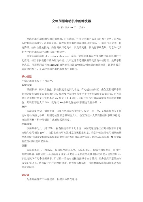
图 2 陷波滤波器设置图
在谐振频带太宽时该滤波器不能滤除干净。 速度反馈滤波器
速度反馈滤波器也为一阶延迟滤波器,这是一个纯粹的惯性环节,相移趋于 90°。在 高频时增益小,当高频处有几个谐振点时适用。增益在-3db 规定为带宽频率,设置范围从 50~1000hz(见图 3)。注意使用时相移可到 90°,可能会发生相移引起的振荡。
范围)。若自调整时振荡则降低伺服刚度直到谐振停止。再重复执行自调整,滤波器调整。 各种型号的这类电动机和驱动器均有它自己的调试、控制和设置参数的软件界面,或对
控制器,或对驱动器,但都大同小异,这里不做介绍。在调试的过程中须反复实验观察,根 据使用要求灵活应用。例如在对一个由这类电动机构成的转台测试设备,测量时对转速稳定 要求严格,而对加速度并不做严格要求,只要加速区不是太长就行,被测对象种类较多,重
交流伺服电动机中的滤波器
作 者:西安 786 厂 吴南江
交流伺服电动机的应用已很普遍。许多国家,许多公司的产品在国内都有销售。国内先 从控制器开始开发,再到驱动器,现在也有类似的电动机出现在市场上。随着技术完善,价 格降低,控制性能的提高,操作调试日趋简单,以及系列化、模块化不断发展,用它取代其 他类型的伺服控制电动机已成一种趋势。
图 3 速度反馈滤波器 bode 图
调试设定步骤 1. 先调陷波滤波器 1 和 2 使其振荡值到最小,如果无效果就关闭该滤波器。 2. 再调整相位滞后补偿滤波器。 #24= n×#2 #25= 4×#24 参数#24 为一阶滞后补偿频率#1; 参数#25 为一阶滞后补偿频率#2; 参数#2 为速度控制带宽#1。 设置参数#24 用 n=3,n=2,n=1 来试,不能使振荡停止就关闭该滤波器。 3. 减低参数 #1 的值(伺服刚性设置)。返回到步骤 1。反复调整直至满意。 若自调整时出错,可将负载惯量设置为零,并增加自调范围(参数 #51,自调模式执行
d类功放的rc滤波器

d类功放的rc滤波器
D类功放的RC滤波器是一种用于减小输出信号中脉冲宽度调制(PWM)带来的高频噪音的电路。
在D类功放中,输出信号是以脉冲
的形式进行调制的,这可能会引入一些高频噪音。
为了滤除这些噪音,通常会在输出端添加一个RC滤波器。
RC滤波器由一个电阻(R)和一个电容(C)组成。
当输出信号
通过RC滤波器时,电容会对高频成分进行短路,从而将这些高频成
分滤除掉,只留下较低频的信号。
这样就可以减小输出信号中的高
频噪音,使得输出信号更加平滑。
在D类功放中使用RC滤波器可以帮助提高音频质量,减小输出
信号中的失真和噪音。
然而,需要注意的是,选择合适的电阻和电
容数值是非常重要的,这会影响到滤波器的截止频率和响应特性。
此外,RC滤波器也会引入一定的相位延迟,需要在设计中加以考虑。
总的来说,D类功放的RC滤波器在音频放大电路中起到了重要
作用,能够有效地减小高频噪音,提高音频质量。
在实际应用中,
需要根据具体的要求和条件来设计和选择合适的RC滤波器电路。
德力西电气 DVDT滤波电抗器样本 产品说明书

线圈采用H级漆包扁线(大电流用箔)紧密绕制,能承受极高的dv/dt的电压冲击采用高性能的销式绕组结构,铜排引出,具有直流电阻小、抗电磁力能力强、短时间过载能力强采用环氧树脂浸漆工艺,降低产品噪声,提高耐热等级DV/DT滤波电抗器在远离电机300米处仍能保证满足电机的最大峰值电压规格,延长电缆1000米处仍表现有卓越的性能采用自愈能力更强、损耗角正切值更小、高耐压特性更好、绝缘电阻更高的滤波补偿用电容器,和高负荷、散热特性好、不燃性、高频特性好、抗脉冲性电阻器,与电抗器共同形成谐振回路,实现对高频信号的滤波作用电源类产品G 海拔高度:≤2000m环境温度:-25+50℃空气相对湿度:最湿月的月平均最大相对湿度为90%,同时该月的月平均温度为+25℃工作环境:a.大气中无严重影响电抗器绝缘的污秽及易蚀易爆介质 b.安装场所无剧烈震动和颠簸c.不受雨雪侵袭的场所d.周围环境应有良好的通风条件,如装在柜内,应加装通风设备■工作条件及安装条件主要应用于工业自动化系统中,用于保护电机不受峰值电压的影响。
DV/DT滤波电抗器安装在变频器输出侧,主要功能:有效降低变频电动机端的DV/DT瞬变电压,延长变频器的有效传输距离至300米;防止传输电缆和电机线圈的过早老化和击穿;降低对邻近设备或线路的干扰传播;减少电机接地泄露电流;延长电动机的使用寿命,提高电动机的可靠性和正常运行时间;有效降低电机端脉冲尖峰电压。
■适用范围■认证与标准标准:GB/T19212 Q/DLX368 ■产品特征■ DUT-0150-0.38SC及以上■ DUT-0010~0120-0.38SC电源类产品G注:以上外形尺寸标注误差±10mm,安装尺寸标注误差±5mm,如有变动,以实物尺寸为准。
d类运放rc滤波
D类运放是一种高效的音频放大器,通常用于音频系统中的功率放大。
然而,在某些应用中,可能需要使用RC滤波器来减少D类运放的输出噪声和干扰。
RC滤波器是一种由电阻器和电容器组成的滤波电路,用于将高频噪声从信号中滤除。
D类运放的输出噪声通常是由功率放大产生的电磁干扰(EMI)和热噪声引起的。
这些噪声在高频范围内,因此可以通过RC滤波器进行过滤。
在D类运放中使用RC滤波器需要注意一些关键因素。
首先,电阻器和电容器的值必须精确匹配电路中的其他元件以获得最佳滤波效果。
其次,电阻器和电容器的值和电路设计应考虑到运放的频率响应和其他性能要求。
此外,在使用RC滤波器时还需要考虑电阻器和电容器的功率容量和耐压。
如果电路中的其他部分需要从滤波器中获得电流或电压,那么电阻器和电容器可能需要足够的大以承受这些负载。
同时,还需要考虑滤波器的热稳定性,以避免由于热量积聚而对电路板和其他组件造成损害。
在实际应用中,可以通过实验和调试来优化RC滤波器的设计和配置,以达到最佳的输出性能和噪声抑制效果。
一般来说,对于不同类型的D类运放和电路设计,可能会有不同的最佳滤波器配置和参数。
总之,使用RC滤波器来减少D类运放的输出噪声和干扰是一个常见的做法,但需要注意一些关键因素,包括电阻器和电容器的精确匹配、电路设计、功率容量和热稳定性等。
通过实验和调试,可以优化滤波器的设计和配置,以达到最佳的输出性能和噪声抑制效果。
d类功放 滤波电感

d类功放滤波电感
D类功放滤波电感是一种用于D类功放电路中的电子元件,主要用于实现滤波功能,即滤除不需要的信号或噪声,以提高功放电路的输出质量和稳定性。
D类功放滤波电感通常由线圈和磁芯组成,其工作原理是利用线圈的电感量和磁芯的磁导率来抑制特定频率的信号通过。
在D类功放电路中,输入的音频信号首先经过开关晶体管进行放大,然后通过一个LC滤波网络(由电感和电容组成)来滤除开关晶体管产生的脉冲宽度调制(PWM)信号中的高频噪声。
这个LC滤波网络中的电感就是D类功放滤波电感。
它能够阻止高频噪声通过,只让低频的音频信号通过,从而得到较为纯净的音频信号,再经过输出滤波器滤除载波成分后,最终输出给负载。
D类功放滤波电感的设计和参数选择对整个功放电路的性能具有重要影响。
需要根据具体的电路参数、音频信号特性和使用要求来选择合适的电感值、线圈匝数、磁芯材料等参数。
同时,在应用中也需要考虑电感的散热性能和稳定性等因素,以确保其长期稳定工作。
有源电力滤波器 无功补偿 无源电力滤波器
有源电力滤波器无功补偿无源电力滤波器北京华腾开元电气有限公司属于北京市高新技术企业,坐落于清华科技园区。
公司以清华大学电力系统国家重点实验室为技术依托单位,专业从事电力系统及其自动化领域理论研究、新技术转化、新产品开发及推广。
公司现有员工100余人,其中技术人员60余人,拥有博士、硕士40余名,85%来自清华大学。
公司注重知识创新,目前拥有9项产品专利,3项软件著作权,其中多项产品分别荣获省部级科学进步一等奖一项、二等奖三项、三等奖三项。
公司主要产品:HTAPF-I型有源电力滤波器有源电力滤波器产品概述随着电力电子技术的发展,各种整流器等电力电子装置在工业、交通运输和家用电器中的应用日益广泛,这些非线性负荷带来的谐波问题也日益严重。
谐波使电网损耗增加,占用系统容量,降低电网效率,导致继电保护设备拒动或者误动,干扰工业生产设备的正常运行,严重时导致大面积停电。
谐波电流在有无功补偿电容器等容性设备的电网中流动时,可能由于系统谐振而放大数十倍或者更多,导致电网设备过电压损坏等严重问题。
有源电力滤波器是解决电力系统谐波问题的新型方案,是谐波治理领域的最新成果。
北京华腾开元电气有限公司自成立以来一直跟踪技术前沿,致力于电能质量治理和电力节能设备的研制,开发出CleanPowerTM系列电能质量治理产品,其中HTAPF-I型有源电力滤波器响应速度快,具备连续补偿和动态跟踪补偿能力,谐波滤除率高,与无源滤波器相比不会与电网发生谐振而且还能有效抑制电网本身的谐振,同时根据设定可兼顾无功补偿和三相平衡,是国内有源滤波领域最先进的产品之一。
HTAPF-I型有源电力滤波器可广泛应用于工业、商业和机关团体的配电网中,如:电力系统、电解电镀企业、水处理设备、石化企业、大型商场及办公大楼、精密电子企业、机场/港口的供电系统、医疗机构等。
根据应用对象不同,HTAPF-I型有源电力滤波器的应用将起到保障供电可靠性、降低干扰、提高产品质量、增长设备寿命减少设备损坏等作用。
IGBT模块变流器用DVDt滤波器

IGBT模块变流器用DV/Dt滤波器一.功能和作用◆有效降低变频电动机端的dV/dt电压;◆防止传输电缆和电机线圈的过早老化和击穿;◆显著延长电动机的使用寿命,提供电动机的可靠性和正常运行时间;◆降低对邻近设备或线路的干扰传播;◆减小电机接地泄露电流◆减小打开滤波器与电机之间的接触器所引起的干扰◆有效降低电机端脉冲尖峰电压二.无DV/Dt滤波器对系统产生的影响◆高dV/dt将电机端子处发生严重的电压过冲,使电机匝绝缘击穿,从而使电机过早失效。
◆驱动由于电机载荷产生的浪涌发生跳闸◆由于存在谐波,电机的工作温度升高,从而降低了系统效率并缩短了电机使用寿命。
◆谐波导致电机产生高频噪音。
三.有DV/Dt滤波器对系统产生的益处◆确保电气设备的可靠性、性能和长使用寿命。
◆降低主电源谐波,减小换相缺口◆降低浪涌和峰值电流◆降低低频传导发射◆提高低频传导抗扰◆避免因为电力线干扰发生跳闸三.技术参数:1.冷却方式:自然通风2.绝缘等级:F级3. 感抗:2%或3%压降(允许偏差:±5%)4. 额定电流(有效值):2-490A/相5. 额定电压(有效值):380-4806. 基波频率:≤100Hz7. 相数:三相,两两相之间最大电感量差:<3%8. 开关频率:逆变桥开关频率2-6kHz。
9.相与相之间的电压波形: PWM脉冲电压,峰值1500V10. 电动机电缆最长150M,电缆更长可以多台串联11.最大dv/dt 为3000V/μs,使之小于500V/μS12.过载要求:过载5%(长期运行), 过载10%(30 min), 过载50%(1min) a. 过载期间电抗器不饱和,既电感量变化小于5% b. 过载期间线圈温升小于100K; c. 过载期间铁芯温升小于120K;13.温升:线圈温升小于80K,磁芯温度小于100K14.耐受电压:绕组、磁芯、支架两两之间,AC3500V/50Hz/10mA,1min 绝缘电阻:绕组、磁芯、支架两两之间,>100MΩ(DC1000V)15.热保护:温度控制开关16.跳闸温度:125℃17.最大电压:250V/50Hz18.最大电流:2A19.噪声等级:小于75dB(1米处)20.绝缘材料阻燃等级:UL94V-1或更高21.防护等级:IP00;22.存储条件:温度-40℃~70℃ 23.相对湿度≤90%,无凝露 24.气压70~106KPa 25.工作温度:-30℃~55℃,50℃以上降额使用 26.应用海拔:1000米以下额定电流,1000米以上每升高100米降额1%。
