PacketShaper百科迪产品培训
PKICA基础知识培训

Hi Bob AAlilcicee
解密 Bob
A 发送机密信息给 B, 知道只有 B 可以解密 A 用 B 的公钥加密 (公开) B 使用自己的私钥解密 (保密)
常用的公开密码算法
RSA ➢ Ron Rivest, Adi Shamir和Len Adleman于1977年研制并且1978年 首次发表 ➢ 可以用私钥加密和公钥加密
另一个公开发布(公钥) 如果乙想送秘密信息给甲
➢ 乙获得甲的公钥 ➢ 乙使用该公钥加密信息发送给甲 ➢ 甲使用自己的私钥解密信息
密钥长度:512-2048位(4096)
公钥算法-加密模式
B 的公钥 明文
B 的私钥 明文
HHi iBBoobb AAliclicee
Alice 加密
Ciphertext
数字证书实际上是存于计算机上的一个记录,是由CA签发的一个声明, 证明证书主体(“证书申请者”被发放证书后即成为“证书主体”)与 证书中所包含的公钥的惟一对应关系。证书包括证书申请者的名称及相 关信息、申请者的公钥、签发证书的CA的数字签名及证书的有效期等 内容。数字证书的作用是使网上交易的双方互相验证身份,保证电子商 务的正常进行。
数字证书的基本内容
证书采用格式
辨识数字证书的标识
签名证书采 用的算法
证书有效期限
证书格式: 序列号 签名算法 颁证机构 有效期限
持有人姓名 持有人公钥
颁证机关签名
颁证机构名称
公钥数值及演算标示 确保证书资料不被篡改
• 它不能避免通过附加在其他文档中被伪造, • 无法防止对机密文档(比如支票)的篡改
数字签名的实现
需要一个数字码唯一标识一个人或实体 ➢ 身份证号码? No, 不保密 ➢ 私钥? Yes!
BOL数字IP网络广播产品手册

IP PAS Distribution System BOL-2880网络广播终端 接口说明
1、AC 220 IN: 交流电源输入口. 2、AC 220V SWITCH OUT: 交流电源控制输出.当有音频信号3、输 出时,此端口将输出AC 220V给功放设备.这样,空闲时4、功放设备将 不工作,可节能并提高功放的使用寿命. 5、LINE AUDIO OUT: 音频线路输出.外接功放设备. 6、SPEAKR OUT: 音频功率放大输出监听用.外接两个8Ω/5-8W的定 阻音箱.为正相位端, 为负相位端. 7、FIXED PRESSURE: 定压备份输入端.此功能模块为选配. 8、DATA PORT: 升级调试端口 9、LAN2 OUT/LINE IN: 网络连接端口/扩展线路输入.当内置交换 机模块时,此端口为标准100以太网端口,可连接外接的网络设备;交 换机模块为选配. 10、LAN1 OUT: 网络连接端口.网络端口功能等同于LAN2 OUT. 11、LAN IN: 网络连接输入口.
IP PAS Distribution System BOL-2880网络广播终端 操作简要说明
终端分为脱机、设置和联机三种模式,在液晶屏左上角有提示,如下图.脱 机指终端还没有登录到服务器,原因可能是网络不通或设置不正确;设 置是通过按遥控器的设置键进入的;联机指终端已经登录到服务器,可 以正常工作;
按遥控器的←→方向键可以移动光标,按数字键可修改参数;按↑↓方向键调节 液晶屏对比度;
设置完毕后,按遥控器上设置键退出.如果设置正确,立即会登录到服务器,液晶屏 左上角显示联机;如果设置不正确,液晶屏左上角始终显示脱机;
IP PAS Distribution System BOL-2880网络广播终端 操作简要说明日常使用
Pocket PC 基础知识

Pocket PC 基础知识Pocket PC及PDA近年来在世界各地都风行了起来,但想选购一台合适的机种之前,大概会被市面上乱七八糟的名词弄得晕头转向,因此就先做好功课,充实充实自己的知识吧。
什么是PDAPDA是Personal Digital Assistant的缩写,照中文翻译称为"个人数位助理",它只是个概念,大体上就是一个能更有效率帮忙完成日常杂事的电子设备,主要就是绕着个人资讯管理(PIM)这个议题在打转,广义的来说任何能达到PIM功能的电子设备都能称为PDA,实际上多专门指能方便携带的手持产品。
什么是PIMPIM就是Personal Inforation Manage的缩写,照中文翻译称"个人资讯管理",大体上对商务人士而言包含行程管理、工作管理、名片管理及邮件管理这四个议题(当然还能再延伸),主要就是提供一个介面及资料库来让使用者方便的纪录分析生活周遭中的资讯。
什么是Windows CEWindows CE是微软开发的一套嵌入式作业系统,主要运用在携带型装置及一些自动控制装置的解决方案,它最大的特徵是发展自桌上型的Windows系统,有档案相容性高、功能多样化的特点。
Windows CE能使用Windows 98/Me的软体吗?不行,基本上这是两种硬体架构截然不同的作业系统(98使用x86相容的处理器,CE则大多都不是使用x86的处理器),不过Windows CE保证有限度的支援桌上型PC所使用的档案及文件,且不需要转换。
Windows CE有哪些版本?Windows CE的核心至今已经有1.0、2.0、3.0叁种版本,若细分小改版则是不计其数,因为Windows CE 并非是专为单一装置设计的,所以微软为旗下采用Windows CE作业系统的产品大致分了叁条产品线,Pocket PC、Handheld PC及Auto PC。
什么是Palm size-PC及Pocket PCPocket PC依照翻译称为"口袋型电脑",大多具有直式(2:3)的触控显示幕并采用笔来输入,使用Windows CE 2.x版以前的称为Palm size-PC,最新采用Windows CE 3.x版的则称为Pocket PC。
Blue Coat
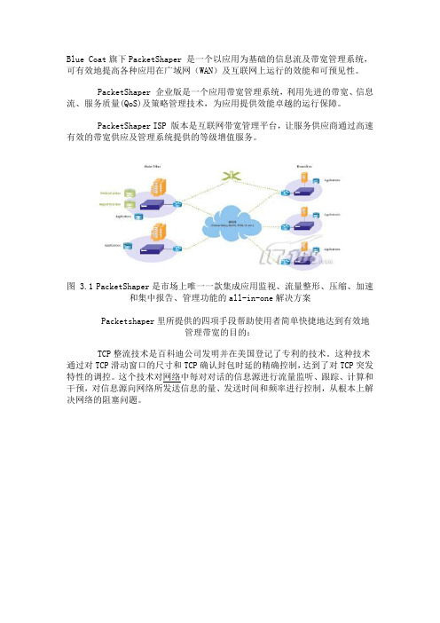
Blue Coat旗下PacketShaper 是一个以应用为基础的信息流及带宽管理系统,可有效地提高各种应用在广域网(WAN)及互联网上运行的效能和可预见性。
PacketShaper 企业版是一个应用带宽管理系统,利用先进的带宽、信息流、服务质量(QoS)及策略管理技术,为应用提供效能卓越的运行保障。
PacketShaper ISP 版本是互联网带宽管理平台,让服务供应商通过高速有效的带宽供应及管理系统提供的等级增值服务。
图 3.1 PacketShaper是市场上唯一一款集成应用监视、流量整形、压缩、加速和集中报告、管理功能的all-in-one解决方案Packetshaper里所提供的四项手段帮助使用者简单快捷地达到有效地管理带宽的目的:TCP整流技术是百科迪公司发明并在美国登记了专利的技术。
这种技术通过对TCP滑动窗口的尺寸和TCP确认封包时延的精确控制,达到了对TCP突发特性的调控。
这个技术对网络中每对对话的信息源进行流量监听、跟踪、计算和干预,对信息源向网络所发送信息的量、发送时间和频率进行控制,从根本上解决网络的阻塞问题。
图 3.2 PacketShaper整形效果经过TCP整流技术处理后的信流变得很平滑,不再严重突发影响其他信流,传输效率大大提高,使广域网资源得到充份利用。
由于TCP整流技术不采用队列技术,大大地减少了信息包的丢失,降低了信息包重发率。
利用TCP整流技术,网络中所有机器的发送量都受到统一控制,从路由器流过的流量如果被控制到与广域网瓶颈带宽相一致,路由器上再不会有大量的队列,这就减轻了路由器的负担使信息包通过路由器的所需时间大大减少响应时间管理(RTM)可使用户的业务在受到破坏之前具体化用户抱怨或评估性能问题。
利用比较实际与预计性能的机制,服务水平协议变得更具有效力。
此外,量化与校验性能要求的能力有助于推断新应用和业务的需求是否能为网络资源所承载,更好为未来规划。
PacketSeeker/PacketShaper的RTM功能可提供性能统计、阈值监视、高级故障指示器和性能图形。
PacketShaper系统恢复手册_v1.0

文件编号:/pk8Packet Shaper系统恢复手册版本:1.0xx网络2010年4月文件说明本程序文件对公司为客户提供的系统集成及相关服务、网络安全服务的实施过程进行了策划和控制。
公司名称:x x x x x x x x系统股份有限公司网址:w w w.x x x.x x x电话:8610-x x x x x x x x传真:8610-x x x x x x x x地址:北京市朝阳区x x x x x x x x x x x x邮编:100x x x文件修订记录公司名称:x x x x x x x x系统股份有限公司网址:w w w.x x x.x x x 电话:8610-x x x x x x x x传真:8610-x x x x x x x x 地址:北京市朝阳区x x x x x x x x x x x x邮编:100x x x目录1Packet Shaper无法启动现象 (5)2系统恢复 (7)2.1方法1 (7)2.2方法2 (10)3管理口总结 (15)公司名称:x x x x x x x x系统股份有限公司网址:w w w.x x x.x x x电话:8610-x x x x x x x x传真:8610-x x x x x x x x地址:北京市朝阳区x x x x x x x x x x x x邮编:100x x x1Packet Shaper无法启动现象设备启动后,Console显示如下:M200 Boot Monitor v1.1Copyright(c) Packeteer Inc., 2000-2006================================================Boot Monitor Menu Secondary: Flash================================================A) Display System ConfigurationB) Configure IP AddressC) Browse Directory ContentsE) Download File via LAN (TFTP GET)F) Upload a File via LAN (TFTP PUT)G) Erase and reload PacketShaper Compact FlashH) Erase and reformat PacketShaper Hard DiskI) Upgrade BIOSJ) Perform Hardware ResetK) PingL) Upgrade Boot MonitorMonitor Selection (menu=?):下面是设备具体启动信息,备注而已:Booting 'Packeteer Monitor'kernel /vmlinuz rw root=/dev/ram ramdisk_size=120000 console=ttyS0,9600 quiet i de=nodma[Linux-bzImage, setup=0x1400, size=0x16960d]initrd /m200rd.gz[Linux-initrd @ 0x3d26b000, 0x1d544cc bytes]audit(1271675449.502:0): initializedINIT: version 2.85 booting公司名称:x x x x x x x x系统股份有限公司网址:w w w.x x x.x x x电话:8610-x x x x x x x x传真:8610-x x x x x x x x 地址:北京市朝阳区x x x x x x x x x x x x邮编:100x x xStarting udev: [ OK ]Initializing hardware... storage network audio done[ OK ]Configuring kernel parameters: [ OK ]Setting clock (localtime): Mon Apr 19 11:11:06 PDT 2010 [ OK ]INIT: Entering runlevel: 2:Entering non-interactive startupStarting lm_sensors: [ OK ]M200 Boot Monitor v1.1Copyright(c) Packeteer Inc., 2000-2006================================================Boot Monitor Menu Secondary: Flash================================================A) Display System ConfigurationB) Configure IP AddressC) Browse Directory ContentsE) Download File via LAN (TFTP GET)F) Upload a File via LAN (TFTP PUT)G) Erase and reload PacketShaper Compact FlashH) Erase and reformat PacketShaper Hard DiskI) Upgrade BIOSJ) Perform Hardware ResetK) PingL) Upgrade Boot MonitorBooting 'Packeteer Monitor'kernel /vmlinuz rw root=/dev/ram ramdisk_size=120000 console=ttyS0,9600 quiet i de=nodma[Linux-bzImage, setup=0x1400, size=0x16960d]initrd /m200rd.gz[Linux-initrd @ 0x3d26b000, 0x1d544cc bytes]audit(1271675811.208:0): initializedINIT: version 2.85 bootingStarting udev: [ OK ]Initializing hardware... storage network audio done[ OK ]Configuring kernel parameters: [ OK ]Setting clock (localtime): Mon Apr 19 11:17:07 PDT 2010 [ OK ]公司名称:x x x x x x x x系统股份有限公司网址:w w w.x x x.x x x电话:8610-x x x x x x x x传真:8610-x x x x x x x x 地址:北京市朝阳区x x x x x x x x x x x x邮编:100x x xINIT: Entering runlevel: 2:Entering non-interactive startupStarting lm_sensors: [ OK ]M200 Boot Monitor v1.1Copyright(c) Packeteer Inc., 2000-2006================================================Boot Monitor Menu Secondary: Flash================================================A) Display System ConfigurationB) Configure IP AddressC) Browse Directory ContentsE) Download File via LAN (TFTP GET)F) Upload a File via LAN (TFTP PUT)G) Erase and reload PacketShaper Compact FlashH) Erase and reformat PacketShaper Hard DiskI) Upgrade BIOSJ) Perform Hardware ResetK) PingL) Upgrade Boot MonitorMonitor Selection (menu=?): ?从上述信息判断,PacketShaper设备是启动到Boot Monitor模式,可以换句话说是启动到“故障恢复”模式。
ESPRIT 初级培训手册

ESPRIT图形用户界面..................................................1-2 菜单................................................................1-3 缺省工具条..........................................................1-3 Smart Toolbar.......................................................1-3 使用ESPRIT..........................................................1-4 文件管理............................................................1-4 ESPRIT选项......................................................... 1-8 工具条..............................................................1-12 元素选择............................................................1-12 平移,缩放和旋转视图.................................................1-14 几何创建............................................................1-15 输入数值............................................................1-15 不带边界几何....................................................... 1-15 边界几何............................................................1-16 工作平面............................................................1-16 特征................................................................1-17 特征类型............................................................1-17 特征创建............................................................1-18 编辑特征............................................................1-18 特征属性............................................................1-19 特征与工作平面关联..................................................1-19 练习:创建特征.......................................................1-19
Packeteer产品使用手册
Packeteer产品使用手册产品使用详解1-1适用Packeteer公司 PacketShaper®产品For Packeteer’s PacketShaper® and PacketShaper Xpress Products2004年1月Packeteer, ChinaCupertino, CA 95014408.873.4400info@ | Packeteer、Packeteer徽标、Packeteer与Packeteer徽标的各种结合、及 AppCelera、PacketSeeker、 PacketShaper、 PacketXpress、PacketShaper Xpress、PacketWise和PolicyCenter是Packeteer公司在美国以及其他国家的商标和注册商标。
本文档中使用的其他产品和公司名称仅用于标识目的,可能是其他公司的商标,为其各自所有者的财产。
Copyright © 2001-2003 Packeteer, Inc.。
保留全部权利。
未经Packeteer公司明确书面许可,均不得对本出版物的任何部分进行复制、影印、存储于检索系统、传播或翻译成其他语言。
Packeteer软件并不出售,仅发放许可证,其使用受最终用户协议中规定的许可条件约束。
PacketShaper提供三种的管理及使用界面,包控制台管理界面、WEB管理界面及Telnet管理。
下面将详细介绍其功能。
1控制台管理界面(Console Interface)1.1 超级终端或其它终端工具设置终端的设置如上图,9600 bps, 8 data bits, 1 stop bit, no parity, hardware flow control。
1.2 向导设置首次启动PacketShaper时会要求输入口令,PacketShaper出厂的口令为空,回车即可。
回车以后紧接着提示是否要初始化PacketShaper,输入“yes”或“Y”回车即可。
Packeteer

产品引入
美国百科迪-PacketShaper
12
Packeteer 实现的第一步
对网络上应用流有 能见度
分类
应用
Slide 13
分类--能见度
Packeteer 自动寻找450种 以上不同协议和应用
Slide 14
分类的标准
▪ Inbound/Outbound (连接分类) ▪ 协议分类 ▪ 端口分类 ▪ IP地址, MAC 地址, 主机名称, 主机列表 ▪ 网段分类 ▪ URL ▪ 具体的应用分类
Listener)
▪ 饼图显示了前10位应用最大的带宽
占用分布情况
▪ 应用响应情况分析 ▪ 最差主机/ 服务器
峰值更能说明真实情况: 突发情况会耗费3 Mbps链 接的100%,而一般情况
只会使用小于900kbps 告诉你是谁在使用 您的广域网资源
Slide 18
分析 –是网络还是应用问题
瞬间网络拥堵 导致:
Slide 38
成功案例
▪ 进出口银行、中行上海分行、民生银行、光大银行、
中信银行、华夏银行
▪ 南方航空公司、北方航空公司、新疆航空公司 ▪ 海关总署、北京海关、厦门海关、广东海关、天津海
关等
▪ 上汽集团 ▪ 江苏省烟草局 ▪ 中国海洋石油、中国石油、 ▪ 华为公司、UTstarcom、中兴等 ▪ 农业部、外交部、商务部
Slide 39
华能国际
华能国际总部
视频终端
MCU 服务器
用户
Packeteer Packeteer ReportCenter PolicyCenter
PACKETEER
PacketShaper 2500
SPFTCAOALTIOUTLNWOIT/NRIN/LTLSUNRUETLKTIS/ISNKRTIDR/ONRSKEKLIPDESE8500
五大工具培训

五大工具培训五大工具培训是指针对企业中五大工具应用进行的培训。
五大工具包括:APQP(Advanced Product Quality Planning,高级产品质量策划)、FMEA(Flure Modes and Effects Analysis,故障模式与影响分析)、MSA(Measurement System Analysis,测量系统分析)、SPC(Statistical Process Control,统计过程控制)和PPAP (Production Part Approval Process,生产件批准过程)。
五大工具在企业中具有重要的应用价值,可以帮助企业提高产品质量,降低生产成本,提高生产效率。
本文将对五大工具培训进行详细解析。
一、APQP培训APQP培训旨在帮助企业掌握高级产品质量策划的方法和技巧。
通过APQP培训,企业可以了解如何从产品设计、工艺策划、生产准备、生产过程控制等方面全面策划产品质量,确保产品从设计到生产的每一个环节都符合质量要求。
培训内容包括:APQP的基本概念、策划过程、策划工具、策划文件的编制等。
二、FMEA培训FMEA培训旨在帮助企业掌握故障模式与影响分析方法。
FMEA 是一种系统化的风险识别方法,可以帮助企业在产品设计、工艺策划和生产过程中识别潜在的质量问题和风险,并采取相应的预防措施。
培训内容包括:FMEA的基本概念、分析方法、实施步骤、案例分析等。
三、MSA培训MSA培训旨在帮助企业掌握测量系统分析方法。
测量系统是产品质量控制的重要手段,MSA可以帮助企业评估测量系统的准确性、可靠性和稳定性,确保测量数据的有效性。
培训内容包括:MSA的基本概念、分析方法、实施步骤、案例分析等。
四、SPC培训SPC培训旨在帮助企业掌握统计过程控制方法。
SPC是一种通过对生产过程进行实时监控和数据分析,及时发现和解决生产过程中出现的问题,保证产品质量稳定的方法。
培训内容包括:SPC的基本概念、控制图制作、过程能力分析、实施步骤等。
PacketShaper Manual v2.0

PacketShaper产品使用手册本手册适用于PacketShaper 1400,1700,3500,7500,10000一、 序言本章将介绍PacketShaper产品的初始化安装和设置。
Packeteer公司PacketShaper的用户使用手册提供了帮助菜单栏里从标准Web-Base用户接口到PacketShaper的帮助信息。
如需要全部的PacketShaper产品文档,包括PacketShaper 用户手册,请查看Packeteer公司的网站:/documentation/packetguide/7.3/documents/。
当然也可从随机光盘中找到。
二、 硬件安装1)设备上架,设备为1U或2U高度,标准19英吋机架2)设备连线下图为PacketShaper的标准连接方法,可根据实际拓朴情况进行适当调整(PacketShaper与交换机相连用普通直通双绞线,与路由器相连采用交叉双绞线,如果是光纤接口则无此要求)图13)使用 Console Cable 一端接 Packetshaper Console Port 另一端接PC / NoteBook 的 COM1 或 COM2 Port4)使用 Windows Terminal (9600,n,8,1)或者其它终端工具连接至PacketShaper Console端口执行一些基本参数设置,如IP地址和子网掩码及网关Setup ipaddress x.x.x.x 255.255.255.0Setup gateway x.x.x.x5)通过标准浏览器,以web方式登录设备进行相关设置。
Sample:Setup ipaddress 10.4.7.19 255.255.255.0Setup gateway 10.4.7.2注:如果设备在出厂设置状态,还可以通过标准浏览器登录http://207.78.98.254访问设备,初始密码为空。
三、 软件配置1) 浏览器设置IE 7.0设置如下图2点击图中红色标记处,打下图图3将PacketShaper的IP地址输入到红色标记处,点击右边的“Add”按钮,如下图图4确认PacketShaper地址被加入到IE弹出窗口允许列表中图5在IE的地址栏中输入PacketShaper设备的地址,http://10.4.7.19,出现登录界面,此为普通登录界图6在IE的地址栏中输入PacketShaper设备的地址,http://10.4.7.19/,出现登录界面,此为安全登录界图7显示当前设备相关信息(产品型号,IP地址,序列号,软件版本,接口类型和当前速率,访问权限以及相关的错误信息(如果有的话))图8“setup Æ basic”标签,配置设备基本信息:“Shaping:”显示当前设备状态(”on”,表示控制功能有效状态,”off”,无控制功能,只能监测,”watch”,端口镜像模式);“Traffic Discovery:”显示当前设备是否自动发现链路中的应用类型(”on”,表示自动发现,”off”,表示不自动发现);“Compression:”显示设备是否具有数据压缩功能;“Adaptive Response:”显示设备异常监测功能是否有效;“Unit Name:”设备名称,如”BeijingDevice”;“IP Address:”设备IP地址,如”10.4.7.19”;“Net Mask:”设备子网掩码,如”255.255.255.0”;“Gateway:”网关地址,如”10.4.7.2”;“Site Route:”选择需要管理哪个路由器(如果有多个路由器和接入线路的话,设置成”none”,表示管理所有经过Packeteer设备的流量)流入的数据流,如”10.4.7.2”或”none”;“Domain:”设置设备所有域的域名(可选项),如””;“DNS Server(s):”设置DNS服务器,(可选项,最多可设置8个,每个IP地址之间中间用空格分隔),如”10.4.30.252”;“Inbound/Outbound Rate:”设置链路的带宽(流入和流出);“Inside/Outside Fast Ethernet NIC Mode:”设置网络接口匹配模式(根据接口类型(光口或电口)可能会有不同的选择项);“setup”选项下的各设置参数图10“setup Æ date&time”标签,配置时间和日期选项:“Time Zone:”选择设备所在地的时区;“Date:”设置设备日期;“Time:”设置设备时间;“SNTP Client:”设置是否使用时间同步服务器;“SNTP Poll Seconds:”与时间同步服务器同步时间间隔;“SNTP Primary:”第一时间同步服务器地址或域名;“SNTP Secondary:”第二时间同步服务器地址或域名;“setup Æ security”标签,配置相关安全选项“Look Password:”设置只可查看的密码;“Touch Password:”设置可更改配置的密码;“Inside/Outside Interfaces:”设置是否可以通过Inside/Outside端口来管理设备(”unsecure”不作任何限制,”secure”禁止从此端口来管理设备,”list”只有list指定的IP地址可以通过此端口管理设备);“Modem On Console”设置成默认值;“Offline Reports:”设置是否支持离线报告;“Unit Access:”设置可能通过哪些方式访问设备(HTTP,HTTPS,TELNET,SSH,FTP,SNMP,TCP ECHO);“Login Message”设置登录提示信息。
过电缆封隔器培训手册

贝克“DESP”封隔器培训手册贝克公司产品系列号为H78560的“DESP”型封隔器是为便于电潜泵(ESP)生产而设计的。
本手册将针对该型号过电缆封隔器的特点、结构、原理、操作规程及注意事项等方面进行逐一阐述。
一、“DESP”型封隔器的特点1、部件较少,设计简单,可方便的回收及修理。
2、坐封及解封容易,液压坐封,上提管柱剪断剪切环解封。
3、设计简短紧凑,长度不足3英尺,便于下入及操作。
4、有单独的气体排放管。
5、有可选的通过封隔器的通道。
6、油管与电缆之间没有相对运动,消除电缆应变。
7、在坐封位置机械锁定,整体锁环使封隔器可保持在坐封位置。
8、双向、整体卡瓦不需要液压控制,上下锥体使卡瓦锚定住套管壁,可使封隔器双向承受载荷。
9、双向承压,当压力从上下两个方向增加时,密封元件密封更好、卡瓦锚定更牢靠。
10、螺纹连接可用于大多数其他直通系统。
二、不同规格“DESP”封隔器相关参数:三、“DESP”封隔器结构该封隔器主要由以下几部分构成:①本体部分,包括本体、上下通径环、下端盖、开口环、止动块、定位销钉。
②密封部分,包括封隔器胶筒及所有“O”形盘根及“O”形盘根支撑环。
③坐封部分,包括活塞套、坐封活塞、坐封销钉。
④锁紧部分,包括主体锁环、键。
⑤锚定部分,包括上下锥体、卡瓦套、卡瓦、卡瓦弹簧、弹簧、滑动销钉。
⑥解封部分,包括剪切套,剪切环。
⑦附件部分,包括过电缆密封筒,放气阀,压力计电缆/毛细管和注入管线穿越孔。
各部分元件的分布及结构详见附图。
四、“DESP”封隔器的工作原理封堵住封隔器大通径底部,向封隔器加液压,液体通过本体上的传压孔作用于坐封活塞上,当压差达到800—1100PSI时,剪断坐封销钉,同时,卡瓦套及下锥体上的剪切销钉也被剪断,当压差达到1200—2000PSI时,卡瓦套及上锥体上的剪切销钉被剪断,卡瓦锚定住管柱,保持2500PSI的压力,使封隔器胶筒压缩完全。
锁紧部分使封隔器始终保持密封状态。
迪普科技产品培训资料

虚拟防火墙
虚拟防火墙
虚拟防火墙
安全域1 安全域
安全域2 安全域
安全域3 安全域
虚拟防火墙组网示意
Page 12
全千兆网络接口
千兆到桌面已是趋势,千兆口和百兆口在对接时,由于各厂商芯片不同,可能出现 不兼容 即使性能升级,受百兆接口最大转发能力限制,也无法实现性能的真正升级。 内网交换流量极易超过百兆 需要多少个千兆接口?
有线无线一体化
•支持WIFI模块与3G模块,业界唯一
Page 17
17
友商竞争分析
厂商
TRX
说明
1、组网限制多:在山西电子政务网MPLS VPN中不支持MCE功能、在山西省委项目中不支持 路由模式下的双机、在山东农行中无法部署在开启STP环境中,不支持子接口功能,无法实现 多VLAN业务处理。 2、不支持3G模块和WIFI模块 3、不支持协议库和URL库 4、研发投入停滞:投入不足,研发遇到瓶颈,近两年FW无新产品、万兆防火墙迟迟没有商用
DPtech UTM多功能开启后性能下降最少! 多功能开启后性能下降最少! 多功能开启后性能下降最少
Page 23
License功能扩展 :基于网络的病毒防护 功能扩展1: 功能扩展
病毒
办公PC
有病毒样本的主机或网站
目标网络 DPtech UTM
办公PC
HTTP、FTP、Email、IM、P2P...
Page 18
18
应用防火墙关键引导点
面向应用防火墙,支持协议库、URL库等功能扩展 面向应用防火墙,支持协议库、URL库等功能扩展 接口引导是关键 全千兆,且接口数>=6个 全千兆,且接口数>=6个 >=6 百兆产品支持千兆光口 千兆产品支持万兆接口 全内置硬件IPSec、 VPN加密 全内置硬件IPSec、SSL VPN加密 IPSec 支持丰富的路由协议 支持WIFI模块(预计10月份可提供) 支持WIFI模块(预计10月份可提供) WIFI模块 10月份可提供 支持3G模块 支持3G模块 3G
PacketShaper 产品说明书
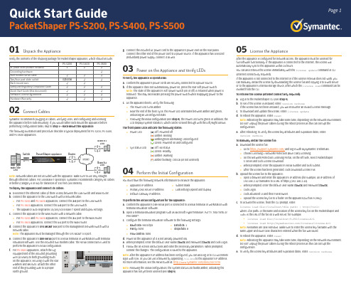
Page 101 Unpack the ApplianceVerify the contents of the shipping package for PacketShaper appliance, which should include:PS-S200PS-S400PS-S500AC power cords (number included)122Grounding hardware √Null-modem serial cable √√√Two/four post slide-rail kit Optional√√Rack-mount ears√√Safety and Regulatory Compliance Guide √√√Quick Start Guide (this document)√√√Software License Agreement √√√Hardware Warranty√√√02 Connect CablesSymantec recommends plugging in cables, verifying LEDs, and configuring and licensingthe appliance before rack-mounting. If you would rather rack-mount the appliance before performing configuration tasks, skip to Step 7—Rack-Mount the Appliance .The following illustration and procedure describe a typical deployment for PS-S200, PS-S400, and PS-S500 appliances.Note: Network cables are not included with the appliance. Make sure to use only straight-through Ethernet cables. For 1000Base-T operation, Symantec recommends Category 5E cables or better (Category 6 or 6A) for distances of 330 feet (100 meters). To deploy the appliance and connect its cables:a. Disconnect the Ethernet cable (if there is one) between the LAN switch and WAN router.b. Connect the appliance to the LAN switch with a network cable:o For PS-S200 and PS-S400 appliances, connect the 2:0 port to the LAN switch. o For PS-S500 appliances, connect the 1:0 port to the LAN switch.o The appliance auto-negotiates 10/100/1000 Base-T speed and duplex settings.c. Connect the appliance to the WAN router with a network cable:o For PS-S200 and PS-S400 appliances, connect the 2:1 port to the WAN router. o For PS-S500 appliances, connect the 1:1 port to the WAN router.d. Connect the appliance’s SYS MGMT 0:0 port to the management network switch with a network cable.Note: The appliance must be managed through the SYS MGMT 0:0 port.e. Connect the appliance’s DB9 seria l port to a serial terminal or workstation with terminal emulation software. Use the included null-modem cable. The serial connection is used to perform the appliance’s initial configuration.f. For PS-S500 appliances, attach the lug-equipped end of the included grounding wire (10 AWG) to both grounding studs on the appliance, securing it with the star washers and M5 nuts. Attach the other end of the grounding wire to a proper earth-ground.g. Connect the included AC power cord to the appliance’s power inlet on the rear panel. Connect the other end of the power cord to a power source. If the appliance has a second (redundant) power supply, connect it as well.03 Power on the Appliance and Verify LEDsTo verify the appliance is operational:a. Confirm the appliance’s power cords are securely connected to a power source.b. If the appliance does not automatically power on, press the rear soft power switch.Note: The state of the appliance’s soft power switch (on or off) is retained when power is removed. This may necessitate pressing the power switch when reapplying power to the appliance.c. As the appliance boots, verify the following: o The Power LED turns amber.o Near the end of the boot cycle, the Power LED alternates between amber and green, indicating an unconfigured state. o Following the initial configuration (see Step 4), the Power LED turns green. In addition, the LCD displays system statistics, which can be scrolled through with the Left/Right Arrows.The front-panel LEDs indicate the following states:: o Power LED (•) Off: Powered off (•) Amber: Booting(•) Amber/green alternating: Unconfigured (•) Green: Powered on and configuredo Sys Status LED (•) Off: No status (•) Green: Healthy (•) Amber: Warning (*) Amber blinking: Critical (or not licensed)04 Perform the Initial ConfigurationYou must have the following network information to initialize the appliance: o Appliance IP addresso Subnet masko Primary DNS server IP address o Link settings (speed and duplex)o Default Gateway IP addressTo perform the initial configuration for the appliance:a. Confirm the appliance’s DB9 serial port is connected to a serial terminal or workstation with terminal emulation software.b. Open a terminal emulation program such as Microsoft HyperTerminal®, PuTTY, Tera Term, or ProComm™.c. Configure the terminal emulation software to the following settings: o Baud rate: 9600 bps o Data bits: 1 o Parity: none o Stops bits: 8 o Flow control: noned. Power on the appliance (if it is not already powered on).e. When prompted, enter the default User Name [touch ] and Password [touch ] and click Login.f. Follow the on-screen instructions and enter the necessary parameters. When prompted, commit the changes. The configuration is saved to the appliance.Note: After the appliance’s IP address has been configured, you can also log in to CLI via remote login with SSH, or you can use a browser by appending /cli.htm to the appliance’s IP address. For more information, see the PacketGuide at: /docs/DOC9776Note: Following the initial configuration, the System Status LED blinks amber, indicating the appliance has not yet been licensed (see Step 5).05 License the ApplianceAfter the appliance is configured for network access, the appliance must be licensed for full software functionality. If the appliance is connected to the Internet, the license will automatically sync to the appliance within 24 hours.You can also retrieve the license immediately with the license update command in CLI (Internet connectivity required).If the appliance is not connected to the Internet or if the license retrieval does not work, you can manually install the license by downloading the license file and copying it to a web server or to the appliance’s internal storage device, after which the license load command can be invoked from the CLI.To retrieve the license (Internet connectivity required):a. Log in to the PacketShaper CLI (see Step 4).b. To see if the license is installed, enter: version verboseIf the license has not been installed, you will encounter an Invalid License message.c. To download and update the license, enter: license update d. To reboot the appliance, enter: resetNote: Rebooting the appliance may take some time, depending on the network environment. DO NOT unplug the power cables during the reboot process as this can corrupt the configuration.e. After rebooting, to verify the license key attributes and expiration dates, enter: version verbose To manually install the license file:a. Download the license file:o Go to https:/// and log in with MySymantec credentials. o Choose Licensing > Network Protection (Blue Coat) Licensing.o On the Network Protection Licensing Portal, on the left side, select PacketShaper S Series and click License Download. o When prompted, enter the appliance’s serial number and click Submit. o After the license has been generated, click Download License File.b. Upload the license file to the appliance:o Open a browser and enter the appliance’s IP address (for example, an IP address of 192.168.2.42 translates to a URL of https://192.168.2.42). o When prompted, enter the default User Name [touch ] and Password [touch ]. o Click Login.o Click Advanced UI and then File Browser.o Upload the license key file to a folder on the appliance (such as 9.256/).c. To activate the license, from the CLI prompt, enter:license load file://localhost/<file path> | http://<url>where <file path> is the name and location of the license key file on the PacketShaper and <url> is the URL of the file on a web server, for example:• license load file://localhost/9.256/license.bcl• license load /licenses/license.bcl Note: Filenames are case sensitive. Make sure to enter the license key filename with the same upper and lower case characters entered when the file was saved.d. To reboot the appliance, enter: resetNote: Rebooting the appliance may take some time, depending on the network environment. DO NOT unplug the power cables during the reboot process as this can corrupt the configuration.e. To verify the license key attributes and expiration dates, enter:version verbosePacketShaper PS-S200, PS-S400, PS-S500RouterSwitch Main Site LANBranch 1LANBranch 2LANPacketShaper AppliancePage 2PS-S200, PS-S400, PS-S500 Quick Start Guide 06 Perform a Graceful ShutdownBefore proceeding to rack-mounting the appliance, log in to the PacketShaper CLI and perform a graceful shutdown of the appliance.To perform a graceful shutdown:a. Log in to the PacketShaper CLI (see Step 4).b. Enter: shutdownWarning: Do not power off the appliance with the soft power switch or by removing the power cables! Abruptly removing power can result in irreparable data loss. Always use the shutdown command from the CLI to power off the appliance.07 Rack-Mount the ApplianceThe slide-rail mounting kit included with the PS-S400 and PS-S500 appliances (available as an option for PS-S200 appliances) allows the appliance to be rack-mounted in a two- or -four-post equipment rack. The slide-rail kit includes the following parts:Note: To rack-mount the appliance, you may need an M4 nut driver or adjustable wrench, #2 Phillips head screwdriver, and rack screws.Note: The following procedure documents how to install the appliance in a four-post equipment rack. For comprehensive information on rack-mounting the appliance, including other configurations, see the S-Series Maintenance and Upgrade Guide at: /docs/DOC9795To install the appliance in a four-post equipment rack:a. Disassemble the two slide-rail assemblies:o Fully extend each slide-rail by sliding out the inner rails until they reach the stop.o Release the white slide latches (toward the rear of the inner rails) and slide the inner rails all the way out. o Slide-rails are symmetrical and can be used with either side of the chassis.b. Attach the two inner rails to the appliance:o Align each inner rail to the mounting posts on each side of the chassis. Slide the rail toward either the front (PS-S200 and PS-S400) or rear (PS-S500) of the chassis until each of the mounting posts snap into place.o Secure the inner rails to the appliance with M3 screws:• For PS-S200 and PS-S400 appliances, use one M3 screw in the center of each rail.• For PS-S500 appliances, use two M3 screws in each rail.c. For PS-S200 and PS-S400 appliances, install the two rack ears. Align them with the mounting posts on the chassis sides near the front of the appliance and secure them with the included fasteners.d. Assemble the two slide-rails and install them in the rack:o Loosely attach Rail_C to Rail_A. Secure the rails with three M3 screws inserted through the slot in Rail_C and screwed into three holes in Rail_A. Make sure the screws areequidistant from each other so the load will be evenly distributed on the rail. Do not yet fully tighten the screws.Note: The precise attachment location of the screws will depend on how far Rail_C will extend or retract to fit the rack. It may be necessary to remove Rail_C from Rail_A to determine the proper installation length. o Install the assembled slide-rails in the rack:• Secure the front bracket for Rail_A to the outside front of the rack using two rack screws. Do not yet fully tighten the screws. You will do so after the appliance is installed in the rack.• Extend or retract Rail_C to align the rear bracket with the outside rear of the rack. Secure the bracket with two M3 screws. Do not yet fully tighten the screws. You will do so after the appliance is installed in the rack.• Tighten the side-mounting screws for Rail_C.• Verify the slide-rail assemblies are installed at the same rack eight.e. Install the appliance in the rack:o Align the inner rails attached to the appliance with the slide-rails in the rack and slide the appliance half-way into the track.o Press the gray locking tabs on the inner rails to slide the appliance all the way into the rack. o Slide the appliance out of the rack, far enough to access the rack screws. Fully tighten the rack screws for the front and rear brackets to secure the slide-rails to the rack.o Gently push the appliance all the way to the back of the rack and tighten the thumbscrews on the retaining ears to prevent the appliance from sliding out.f. Reconnect the cables as documented in Step 2—Connect Cables and verify the appliance is functioning as in Step 3—Power On the Appliance and Verify LEDs .Technical Supporto Contact Informationhttps:///en_US/contact-support.html o MySymantechttps://DocumentationPacketShaper Software Documentationo /docs/DOC9776Appliance Documentationo S-Series Maintenance and Upgrade Guide /docs/DOC9795o S200 Series Safety and Regulatory Compliance Guide /docs/DOC10311 o S400 Series Safety and Regulatory Compliance Guide /docs/DOC9996 o S500 Series Safety and Regulatory Compliance Guide/docs/DOC10248CAUTION:Before rack-mounting the appliance:o Power off the appliance and disconnect all cables.o Verify that the weight of the system does not exceed the rack’s fully populated weight limit. For more information, refer to the manufacturer’s instructions included with the rack. o For weight stability, load the rack from the bottom up. o Read the “Rack Mount Warnings” section of the Safety and Regulatory Compliance Guide . o Take adequate safety and grounding measures to avoid creating anelectrical shock hazard and to prevent bodily injury.Rail_CRail_ARail_B (2)(used only for 2-post racks)Rail_C。
布迪-1S-SP产品安装说明书

BUDI-1S-SPI N S T A L L A T I O N I N S T R U C T I O NBuilding distributor• BoxKit contentAccessoriesIntroductionThe Budi is a building distributor for a fiber managment system thatoffers the functions of splicing. Provides a mechanical and environmentalprotection for the fiber optic components.• Loop bracketLoop of 8 loose tubes (ø 2.4 mm).Maximum window of 2 m.SealsWrap around cable seals Sealblock 4 x 10 mm Cable diameter (mm) Foam (± 5 mm)3 954 905 806 757 708 609 50 10 40Sealblock 4 x 15 mm Cable diameter (mm) Foam (± 5 mm)9 125 10 115 11 105 12 95 13 85 14 70 15 60Sealblock 2 x 20 mm Cable diameter (mm) Foam (± 5 mm)14 155 15 140 16 125 17 110 18 95 19 85 20 75Sealblock 24 x 8 mm Cable range 1.8 – 7 mm Sealblock rubber 1 x 18To use in ports S4-S5 only Cable range 3 – 18 mm Standard seals PG 16PG 21PG 29PG 29 (PTS 24)TC-988-IPRev A, Feb 20171.1 Different wrap-around ports are available (including brackets). Use two guiding pins to open the ports and to secure the bottom part tothe box. Cut out the plastic part if you want to install a cable.1.3 Use a hacksaw to reach the onion rings, which can be opened with a plier to open the in-line ports (S4/S5).1.2Install the cable bracket depending the cable seal.1 Preparation of the boxS4S52.1 Install the looped cable into the ports. Check the foam lengthon page 1.1.4Install the wrap-around rubber seal into the port.2Looped cable2.2Store the looped tubes into the loop bracket.3.3Route the fibers or tubes towards the FAS block.3 Drop cables4 Fiber routing3.1 Install the drop cables into the ports. In this case it’s a pushthrough sealing block.3.2 Install the cable into the port and secure with hook and loop fastener tape onto the bracket and seal with foam (see length page 1).FoamHook and loop fastener Hook and loop fastener4.1 Secure the wraparound groove plate on the UMS by putting the plate with the long protrusions in the S1 UMS-profile and sliding the plate in the S2 UMS-profile until it snaps. (Do not leave gaps between groove plates).S1S22.3Route the loose tube towards the FAS block.4.2 To remove push the two snapfits at S2 UMS-profile and slidethe wraparound plate towards S1 UMS-profile.4.3 Place a tray in the wraparound groove plate; do this by pushing the lip on the groove plate (lowest possible position) slightly down with the tray and move the tray lateral into the hinge-cavities of the groove plate. To snap the High Capacity Single Element tray (HCSE) in the W/a single fiber groove plate leave always one hinge facility open between Fasblock or previous tray and the HCSE-tray.4.4 To remove the tray put the fiber guiding pin between lip onwraparound groove plate and tray and move lateral towards S1.4.6 Pull gently on the fibers in the tray and make sure that the fibersare well contained in the routing block and wraparound groove plate.4.5 Position the wedge carefully such that the groove is stillaccessible for the fibers and be careful not to push the wedge against fibers. To remove the wedge,use two hands to pull on both ends (near the groove plate). Route the fiber in the grooves of the wraparound groove plates to the entrance of the identified tray. Fiber must be routedin the groove below the hinge of the tray!5.4RECORDsplice in SC tray.5.5RECORDsplice in SE tray.5.6RECORDsplice/ANT in SC tray.5 Trays5.1SMOUV in SC tray.5.2ANT in SE tray.5.3ANT in SC tray.4.7 Store the fibers temporarily on a tray (picture shows the case of a loopback).4.8 Storing dark fibers can be done in different ways.1) Organise dark fibers into the different trays, following instructions as described.2) Organise dark fibers together into the first available tray (i.e. with amax. of 24cut or 12 loops primary coated fibers in one SE-tray).5.7 Ribbon 4/8 tray.5.8 Ribbon 12 tray.5.9 Use a permanent marker to write on the tray.6.1Close all the ports and the box.6 Closing the box© 2017 CommScope, Inc. All rights reserved.SMOUV , RECORDsplice and all trademarks identified by ® or ™ are registered trademarks or trademarks, respectively, of To find out more about CommScope® products, visit us on the web at 。
SPPID中文培训教材
目录1概述 (5)2项目定制 (5)2.1 模板的定制 (5)2.1.1 I NTERGRAPH缺省的模板文件 (5)2.1.2 修改已有模板 (6)2.1.3 新建模板文件 (6)2.1.4 S MART F RAME P ROPERTIES对话框 (6)2.2 图形符号和标注的定制 (8)2.2.1 图形符号的定制 (8)2.2.1.1 图形符号定制的主要步骤 (8)2.2.1.2 定制图形符号的注意事项 (10)2.2.2标注的定制 (13)2.2.2.1 标注定制的主要步骤 (13)2.2.2.2 定制图形符号的注意事项 (16)2.3 F ILTER M ANAGER (24)2.3.1 新建简单过滤器 (24)2.3.2 新建复合过滤器 (26)2.4 O PTIONS M ANAGER (28)2.4.1 S YMBOLOGY页面 (29)2.4.2 G APPING页面 (31)2.4.3 T RACING页面 (32)2.4.4 F ORMATS页面 (33)2.4.5 D ISTANCES页面 (34)2.4.6 S ETTINGS页面 (35)2.5 R ULE M ANAGER (39)2.5.1 G ENERAL页面 (40)2.5.2 I TEMS页面 (41)2.5.3 C ONSISTENCY页面 (42)2.5.4 I MPLIED I TEMS页面 (43)2.6 F ORMAT M ANAGER (44)2.6.1 新建格式 (45)2.6.2 修改已有格式 (45)2.6.3E DIT F ORMAT P ROPERTIES/A DD F ORMAT对话框 (46)2.6.4 F IELD P ROPERTIES对话框 (46)2.7 I NSULATION M ANAGER (50)2.7.1 新建项目隔热规格文件 (51)2.7.2 创建和编辑隔热规格 (51)2.7.2.2 I NSULATION S PECIFICATION P ROPERTIES对话框 (52)2.8报表的定制 (56)2.8.1 模板的种类及位置 (56)2.8.2 报表编辑器 (57)2.8.2.1 创建报表模板 (57)2.8.2.2 修改报表模板 (58)2.8.3报表的生成 (60)2.8.3.1报表的范围 (60)2.8.3.2选择报表模板 (60)2.8.3.3报表的保存 (60)2.8.3.4报表的后续处理 (61)2.9D ATA D ICTIONARY M ANAGER (65)2.9.1D ATABASE T ABLES页面 (66)2.9.2D ATABASE I TEM T YPES页面 (67)2.9.3S ELECT L IST页面 (68)2.9.4S ELECT E NTRY (68)3图纸管理 (73)3.1 项目信息的设置 (73)3.2 创建空图 (74)3.3 修改PID图的信息和删除PID图 (76)3.4 批打印 (76)3.5 同时选择不同单元中的图纸 (76)3.6 更新图纸 (78)3.6.1 T OOLS>O UT-OF-D ATE D RAWING C RITERIA命令 (78)3.6.2 O UT-OF-D ATE D RAWINGS命令组 (79)3.7 F ILES>I MPORT D RAWINGS (79)4图纸绘制 (80)4.1 SPPID图形环境介绍 (80)4.1.1 菜单和工具栏 (82)4.1.2 属性窗口(P ROPERTIES W INDOWS) (85)4.1.3 E NGINEERING D ATA E DITOR窗口 (86)4.1.4 C ATALOG E XPLORER窗口 (86)4.2 S MART P LANT P&ID中图形符号的分类及基本应用 (87)4.2.1 设备 (88)4.2.1.1 设备的放置及属性的输入 (88)4.2.1.2 设备标注 (88)4.2.1.3 设备部件的放置及属性的输入 (89)4.2.1.5 TEMA换热器的放置 (89)4.2.1.6 驱动设备与驱动标注的区分 (89)4.2.2 管线 (90)4.2.2.1 管线的放置及属性的输入 (90)4.2.2.2 管线的标注 (91)4.2.2.3 管件的放置及属性的输入 (91)4.2.2.4 管件的标注 (91)4.2.3 仪表 (92)4.2.3.1 在线仪表的放置及属性的输入 (92)4.2.3.2 在线仪表标注 (93)4.2.3.3 离线仪表的放置及属性的输入 (93)4.2.3.4 离线仪表标注 (93)4.2.3.5 仪表与仪表标注的区分 (93)4.2.4 组合件(A SSEMBLY) (94)4.2.4.1 创建组合件 (94)4.2.4.2 放置组合件 (94)4.2.5 D ESIGN目录 (94)4.3 图形相关操作 (96)4.3.1 工具栏与快捷菜单 (96)4.3.1.1 鼠标选取控制工具栏 (96)4.3.1.2 标注对齐工具栏 (96)4.3.1.3 对齐示意线 (96)4.3.1.4 图形符号操作点 (96)4.3.1.5 管线的快捷菜单 (97)4.3.1.6 S ELECT C ONNECTED I TEMS对话框 (98)4.3.1.7 标注快捷菜单 (99)4.3.2 图形符号的替换 (100)4.3.3 M OVE T O D RAWING命令 (100)4.3.4 特殊内容的绘制 (101)4.4 属性相关操作 (101)4.4.1 属性输入的自动化 (101)4.4.1.1 I TEM T AG属性 (101)4.4.1.2 与隔热要求相关的属性 (101)4.4.1.3 与管道材料等级相关的属性 (102)4.4.2 属性的快速修改 (102)4.4.2.1 S YSTEM E DITING选项 (102)4.4.2.2 多个物体的属性同时修改 (104)4.4.2.3 属性的复制 (104)4.4.3 属性变化的处理 (104)4.4.4 SPPID数据模型概述 (106)4.4.5 A PPLY D ISPLAY S ETING命令 (106)4.4.5.1 A PPLY D ISPLAY S ETING对话框 (107)4.4.5.2 S ELECT F ILTER对话框 (108)4.4.5.3 在图面上突出显示特定物体 (108)4.4.5.4 隐藏特定的物体 (112)4.4.6 E NGINEERING D ATA E DITOR的使用 (113)4.4.6.1 命令说明 (113)4.4.6.2 S TOCKPILE (116)4.4.6.3 OPC的放置 (116)4.4.6.4 回路号的输入 (117)4.4.6.5 隐含物体属性的输入 (118)4.4.6.6 图面物体的定位 (120)4.4.7 数据报表及外部数据导入 (120)4.4.7.1 报表的生成 (121)4.4.7.2 外部数据导入 (122)4.5 图纸版本管理 (123)4.5.1 保存一张图纸的版本 (123)4.5.2 保存所有图纸的版本 (123)4.5.3 恢复到以前的版本 (123)4.5.4 恢复一张被删除的图纸 (124)4.5.5 恢复图纸过程中应注意的问题 (124)4.5.6 版本比较 (125)4.5.6.1 比较同一数据库中的不同版本 (125)4.5.6.2 C OMPARE对话框 (125)4.5.6.3 C OMPARE AND R EFRESH命令 (127)4.6 实用工具 (128)4.6.1 图形符号路径检查工具-C HECK F ILE P ATH C MD.DLL (128)4.6.2 删除孤儿数据工具-D EL O RP M OD I TEMS.DLL (128)4.6.3 重复位号查找工具-D UPLICATE T AG R EPORT.EXE (129)4.6.4 关系标志符修复工具-R EPAIR R EL I ND C MD.DLL (129)4.6.5 S YMBOLOGY更新工具 (130)4.6.6 设置更新工具-A PPLY S ETTINGS C MD.DLL (130)4.6.7 标注更新工具-U PDATE L ABELS C MD.DLL (130)4.6.8 重新生成图纸工具-R ECREATE D RAWING.DLL (130)1 概述SPPID软件完全安装后,会在程序目录下创建Intergraph SmartPlant Engineering Manager和Intergraph SmartPlant P&ID程序组,这些程序组中的应用程序按功能可分为以下四类:z项目管理Engineering Manager-用于项目的创建、删除、备份、恢复;用户的授权;工厂结构的创建和修改;共享工作模式的创建;Project模式的创建等。
SPPID培训教材
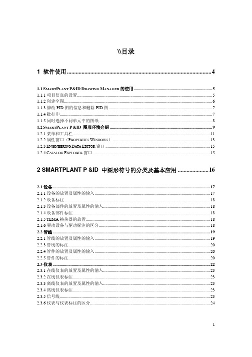
1 软件使用 ...................................................................................................4
1.1 SMARTPLANT P&ID DRAWING MANAGER 的使用 ........................................................................ 5 1.1.1 项目信息的设置............................................................................................................................ 5 1.1.2 创建空图........................................................................................................................................ 6 1.1.3 修改 PID 图的信息和删除 PID 图 ............................................................................................... 7 1.1.4 批打印............................................................................................................................................ 7 1.1.5 同时选择不同单元中的图纸........................................................................................................ 8 1.2 SMARTPLANT P &ID 图形环境介绍 .............................................................................................. 9 1.2.1 菜单和工具栏.............................................................................................................................. 11 1.2.2 属性窗口(PROPERTIES WINDOWS) ......................................................................................... 13 1.2.3 ENGINEERING DATA EDITOR 窗口 ................................................................................................ 15 1.2.4 CATALOG EXPLORER 窗口............................................................................................................ 15
讲义四:服装与环保-bottilippt-Diaposi

法规第33条例所涉及的义务
物质一被列入侯选名单就自动给接受者这提供消息。需注意上述所 提到的接受者是指行业或专业用户及分销商,而不是消费者.
. 供应商根据法规33项第2款所要求的确保物品使用安全的物品信息会 提供给消费者。消费者将在45天内按要求收到该信息。
法规第33条例所涉及的义务(接续)
这些义务不仅限于1吨以上的物品 (也就是这些义务也适用于每年1吨以下).
2)检查供应链是否有列如侯选名单的物质,或用来投入生产的物质,或 未在物品中高度关注物质的确认。核查供应链并要求是否能确认芳香物 质供应商的身份。如果是,服装进口商可以取一份安全数据清单。
4) 核查所确认的物质是否例如侯选名单(排放测试发现合成物质分 成R50/30和R51/53。这些合成物可能达到PBT/vPvB物质的标准, 这些被认为是高度关注物质。
3.物质的释放是物品功能中不可避免的副作用,但是这种释放对物品的功能没有 影响. 例如:在高强度的摩擦的情况下出现磨损及撕裂,例如衬里、轮胎的破损以及用 来减少两个零件之间摩擦的润滑油的泄漏。
4. 物质的释放形成于各种化学反应。 例如:复印机中释放出来的臭氧或者着火物品中释放出来的燃烧物。
5. 意外事件中的物质释放 例如:一支温度计掉落并打破而导致的物质释放。
REACH 化学品的注册、评估及授权
物质: 是指一种化学元素及它的天然状态或在生产加工被赋予的合成物 质,包括能保持物质稳定性的添加物以及加工过程中产生的杂质,但 是并不包括可以被分离出来且并不影响其物质稳定性或能改变其成分 的溶剂;
混合物(配制品): 指一种混合物质或由2种或以上物质组成的混合物;
确认从物品中有意释放的每种物质. 衣服中确认含有11中芳香合成物。在排放测试过程中,发现多种合 成物,一些被发现的合成物都标明CAS NO 及分类。
- 1、下载文档前请自行甄别文档内容的完整性,平台不提供额外的编辑、内容补充、找答案等附加服务。
- 2、"仅部分预览"的文档,不可在线预览部分如存在完整性等问题,可反馈申请退款(可完整预览的文档不适用该条件!)。
- 3、如文档侵犯您的权益,请联系客服反馈,我们会尽快为您处理(人工客服工作时间:9:00-18:30)。
31
Top 10 Report
Report种类 • • • • Total bytes Average Rate Peak Rate Network Efficiency
时间区间 • • • • Hour Day week Month
32
Network Performance summary
• •
Host nn
Host 22
7
网卡类型带来的问题
• •
PS网卡缺省的设置是Auto 但有些老设备不支持auto,唯有手动选择网卡类型
注意事项 :
1. 当机或停电,设备会自动 By Pass 不会影响网络流量 2. 设备会自动检测
1. 使用 Console Cable 一端接 Packetshaper Console Port 另一端接 2. PC / NoteBook 的 COM1 或 COM2 Port 3. 使用 Telix , Windows Terminal (9600,none,8,1) 连接至 PacketShaper 4. Console 执行一些基本参数设置 5. 设置方式 a. 遵循系统指引设置 设置方式: 遵循系统指引设置 b. 手动设置
23
New Traffic Class Matching Rule
24
New Traffic Class Matching Rule
25
如何增加多个规则
设定(请点击 多个Matching Rule 设定 请点击 “class/add Matching Rule”)
当一个分类中需 要多个条件时, 可以增加多个规 则条件,比如刚 才VIP分类,是 一组IP地址时。
经过培训后,你将有能力: • • • • • • • • 有能力安装、配置所有型号的PacketShaper 了解PacketShaper 的各个界面的功能. 对流量进行识别与分类. 为独立的信息流(per-flow)分配实时的带宽策略. 为各种流量划分虚拟通道(Partition). 分析带宽的使用量及其相应的图形报表. 升级软件 故障排除,分析PacketShaper 的状态.
45
Partition最主要的两个目的 最主要的两个目的
Partition可以:
44
整体流量与单一流量 Aggregate vs Flow
• PacketShaper管理流量的两种方式: • Flow(flow-by-flow的管理方式) • 整体流量Aggregate(把整个流量视为一体) • Policies管理单一流量 • Partitions管理整体流量 • Partition主要是在保护重要应用,抑制非关键应用
22
自定义流量分类
• PacketShaper可以自动识别 可以自动识别500种以上的应用 可以自动识别 种以上的应用 • 有些无法识别的流量,可以通过Matching rule方式手工分类 有些无法识别的流量,可以通过 方式手工分类 • 选择 选择Inbound或Outbound,然后点选 或 里的add,即可进 ,然后点选Class里的 里的 , 入自定义流量界面
点选Report进入 进入 点选 将看到Inbound和Outbound各3种 和 将看到 各 种 图形: 图形: - 链路使用率 Link Utilization - 网络效能 Network Efficiency - 前十大用两者 Top 10 Classes
33
连结效率(Link Utilization) 连结效率
3
PacketShaper 流量基本概念
outbound/HTTP/outside (get) inbound/HTTP/outside (data)
Inside
Outside
Client
Inbound
Server
Internet PacketShaper Outbound
Server
Client
21
内建的分类
PacketShaper有些内建的分类 有些内建的分类 • Inbound and Outbound • Inbound/Default and Outbound/Default 所有访问PS本机的流量 本机的流量( • Localhost: 所有访问 本机的流量(通常 指管理者的流量) 指管理者的流量) 内建的分类无法删除
9
PacketShaper 命令行配置 命令行配
• • setup show (显示配置信息) 示配置信息) 设置管理地址 ° 如 setup ipaddress 192.168.0.1 255.255.255.0 • 设置网关 ° 如 setup gateway 192.168.0.254 • • 确设置信息 ° Set show 其他参考使用手册 其他参考使用手册 Chapter 11 使用
钩选 Class 的 Talkers 及 Listeners 功能作 Host Analysis
37
监测流量
Class Hits/Rates可了解哪个服务最忙
Top Talkers/Top Listeners 可了解哪个 IP地址使用最多的频宽
38
各种网络应用的流量报表
39
查看传输延迟
• 针对单一应用或流量观察传输延迟的详细资料
26
如何增加多个规则
如在此处可以再增加一个IP地址或其他条件
27
如何增加多个规则
增加多个Matching Rule 后出现的画面 多个
此处有两个规则
28
擅用流量分类树
流量分类树对管理网络应用带宽有相当大的帮助
• 流量分类树按其组成可分为: 流量分类树按其组成可分为: 1、以应用程序为基础的流量树树形图 、 2、以位置为基础的流量树树形图: 、以位置为基础的流量树树形图: a、单纯以位置区分的流量树 、 b、以位置和每一位置应用程序为基础的流量 、 树 c、以位置和总体应用程序为基础的流量树 、
• 若尖峰用量(Peak Rate) 远高于平均用量(Average Rate)代表您可以 通过 PacketShaper 管理来增加网络线路整体的使用效率
34
网络效率(Network Efficiency) 网络效率
• 网络效率: ° ° • ° ° ° 用最小的成本达到最大的效能 去除网络重传的隐藏性成本 网络管理者 线路管理者 CIO/CFO
10
PacketShaper IE 配置
执行安装指引
11
PacketShaper WEB 管理功能
•
功能介绍 ° 设置(Setup) ) ° 监视(Monitor) ) ° 管理(Manage) ) ° 报告(Report ) 报告( ° 帮助(Help) )
12
中输入PacketShaper的IP地址并回车 在IE中输入 中输入 的 地址并回车
百科迪产品培训
1
课程内容: 课程内容:
—概论-安装 —介绍TCP速率整形技术 —怎样布署PacketShaper —怎样对应用进行分类 —数据报表分析 —报告形式 —软件升级,操作及常见问题解决办法 —控制与带宽分配 —集中管理-ReportCenter、PolicyCenter介绍
2
培训的目标
or Switch
6
全冗余环境的安装方式
WAN
Network Segment Direct Link (copied traffic) Redundant management link
PacketShaper S LAN
Host 2 Host n
PacketShaper S
Host 1
Host 11
inbound/HTTP/inside (get)
outbound/HTTP/inside (data)
4
安装前的准备
•
设备安装之前,工程师首先需要了解到以下信息: 1、物理拓扑——是否冗余?是否需要另外加插LEM卡? 2、网络的带宽 3、网卡的类型 4、口令分配
5
硬件安装
• 核对下面所述: 核对下面所述: • 确认 PacketShaper 的线路安装是正确的 ° 是否Outside 和 Inside 介面连结到正确 Outside 的设备? —Outside介面对 Router —Inside对 LAN. ° 网络线是否使用正确? —Cross-over线路对 router或 firewall. —Straight-through线路对 hub 或 switch. —网线类型选择错误,PS网卡状态灯不 亮
29
第二步
Analyze Network Traffic
针对你的网络应用进行分析
30
分析控管前的状态
• 分析控管前网络带宽的使用状况及重要应用的使用效能 • 同时分析: 同时分析: • TOP 10 Report——Average、peak、total、Efficiency • 网络线路的执行效能——Network Performance summary • 监测各种网络应用的流量情况——monitor traffic • 监测各种网络应用的响应时间——response time
谁会关心?
35
前十大用量—圆饼图 前十大用量 圆饼图
• 快速了解哪一种应用使用了最多带宽
36
监视界面--分析最大使用者 监视界面 分析最大使用者TopTalker&TopListener 分析最大使用者
• • 最多可列出 前12大 talkers/listeners 名单 (全部). 可针对 Top users 单独分类控管
18
监视界面( 监视界面(Monitor) )
我们可以点选Monitor,在其界面里,我们会看到具体的流量分类树 在其界面里, 我们可以点选 在其界面里 注意: 所产生的, 注意:以下画面中的 Class Tree 是因激活 Traffic Discovery 所产生的, 屏幕分辨率最好是1024x768 屏幕分辨率最好是
