组合电源PS48100-225用户手册
PSPS系列有力的电源子woofer产品说明书

RL
Line Input
PS Subwoofer
RCA Phono Cables
R +-
- L+
RL Receiver, TV, or Amplifie
Ⅵ High Quality Active Equalization Amplifier Circuitry: Integrating the acoustic and electronic systems into a single enclosure enable JBL engineers to employ an equalizer circuit that extends the bass response beyond the limitations of a small enclosure.
3
CONNECTIONS CAUTION: Before making any connections to your subwoofer, make sure the power to your entire system is OFF .
POWER Plug the power cord into a grounded wall outlet or the accessory outlet on the back of your amplifier/receiver.
accompanying the appliance.
WARNING - TO REDUCE THE RISK OF FIRE OR ELECTRIC SHOCK, DO NOT EXPOSE THIS APPLIANCE TO RAIN OR MOISTURE.
CAUTION: TO PREVENT ELECTRIC SHOCK DO NOT USE THIS (POLARIZED) PLUG WITH AN EXTENTION CORD, RECEPTACLE OR OTHER OUTLET UNLESS THE BLADE CAN BE FULLY INSERTED TO PREVENT BLADE EXPOSURE.
PS电源说明书
开关模块
导 轨
机箱
2.插入开关模块后 用 螺丝将前面板固定
输入模块 固定螺丝M3 8
接着安装输出模块
图 2.3 开关模块的安装
4
3.将输出模块沿着指向 插座的导轨插入
输出模块
4.插入输出模块后,用 螺丝将前面板固定
导 轨
插 座
PS 系列电源说明书
输出模块 固定螺丝M3 8
下一个输出模块按3 4 相同的顺序安装
空开采用 4 触点空气开关作为控制输入电源通断的装置 工作电压是 100 220VAC 通过前面板的 螺钉固定在机箱正面左起的第一个单元处 安装方法如图 2.3
每个空气开关的背侧有两对接线端子(LINE/LOAD) 即一个空开可以同时控制两路通断
表 2.1 电源空开
机箱
空开
个数
PS6001U 2
PS6010U 1
2
PS 系列电源说明书
1. 概 要 本电源装置采用模块化结构 包括电源机箱和电源模块两个部分 不同的电源机箱用于不同用途
在机箱中可通过多种输出模块的不同组合配置以满足不同的用电需求 每个电源机箱最多含六个输出模块 每个输出模块功率为 65W 为开关式的模块化直流稳压电源
在每个输出模块中内置有双重化对接二极管, 不需在外部设置双重化装置即可构成电源装置的双重化结 构
PS 系列电源输入和输出之间采用变压器隔离
1.1 机 箱 PS 系列电源机箱分为三类 如表 1.1 所示
表 1.1
机箱类别 型 号
机箱
PS6001U PS6010U
PS6011U
用途 接口供电 控制器机箱供电 PS6010 扩展电源
1.2 模 块
电源输出模块有 4 种 如表 1.2 所示
GE 紧急电源 SPS -48V 瘦胖电源架 Quick Start 指南说明书

Document CC848916296r03 2015 AprilSPS J2007003 L011 - Quick Start Guide 1Tools required:Wire cutters and strippers Torque wrench - 0-65 in-lb (0-10Nm) Cable crimpersSockets - 5/16”, 7/16, etc.Screwdrivers - Philips #1 and #2, Flat smallNo vertical spacing is required, allow a minimum 2 inch clearance at back of shelf for rectifier airflow. Refer to Slimline Power System Brochurefor details and accessories.Quick Start GuideGECritical PowerSPS –48V Slimline Power ShelfModels: J2007003L011 - alpha suffixes per Slimline Power System BrochureAC Cord RetainerChassis Ground optionsDC Reference (CO) GroundStep 2 - Connect Chassis Ground and DC Reference (CO) GroundChassis Ground - 10 AWG min recommendedLug Landing: #10 double-hole on 5/8-inch center (lug not provided)Some applications may rely on frame mounting screws for chassis ground, omitting the chassis ground wire. Torque 10-32 screws to 30 in-lb (3.4 Nm) - 5/16” socket. DC Reference (CO) Ground - 10 AWG min recommended Strip 0.6” (15 mm) and insert wire fully into POS RTN block.Step 3 - Connect AC InputL004 - C13 cords (1 or 2). Secure cord with the AC cord retainer (furnished). L014 - wire to AC terminal blocks. Strip 0.3” (8 mm). Torque to 10 in-lb (1 Nm).Danger: If blunt cut cords are used ensure AC power is OFF and use appropriate lock-out tag-out procedures before continuing with acconnections. Follow all local and national wiring rules when connecting to ac mains. Caution: Route AC cables to avoid contact with sharp or rough surfaces that may damage insulation and cause a short circuit.Step 1 - Mount Shelf1. Reposition mounting ears as required - 1 screw each. Torque to 25 in-lb (2.8 Nm) - Phillips screwdriver.2. Attach shelf to the frame using a minimum of four screws (two on each side) - 12-24 (provided). Torque to 35 in-lb (4 Nm) - 5/16” socket.Document CC848916296r03 2015 AprilSPS J2007003 L011 - Quick Start Guide 2Step 4 - Connect DC Output and Battery, and DC Reference (CO) GroundUSB Craft PortJ2 Alarm inputsJ1 Alarm outputsJ3 1-Wire Battery Temp MonitorJ5 LAN PortStep 5 - Set Jumpers - LAN Port and Relay per Galaxy Pulsar Edge Controller Quick Start Guide Signal ConnectionsDC Outputs - GMT style fused (15A max fuses)Connect outputs and returns to the terminal blocks. 12 AWG max Strip 0.35” (9 mm) Torque to 4 in-lb (0.45 Nm)DC Aux Output - optionalConnect Aux output and return to the terminal blocks. 8 AWG max Strip 0.6” (15 mm) Insert wires fully into blockInsert small flat screwdriver to open clamp..BatteryConnect outputs and returns to the terminal blocks. 8 AWG max Strip 0.6” (15 mm) Insert wires fully into blockInsert small flat screwdriver to open clamp..CAUTION : Verify battery voltage and polarity with a voltmeterbefore proceeding.BatteryDC Outputs 1-6 GMT style fused15A max fusesDC Outputs 7-12 GMT style fusedDC Aux OutputDC Reference (CO) GroundConnectors are on rear.1. J1-2 Alarms and Inputs - Connect to office alarms and signals. See Information: Alarm Connections for Details2. J5 LAN - Connect to Ethernet network.Step 6 - Install Controller per Galaxy Pulsar Edge Controller Quick Start Guide Step 7 - Install Signal and Communications Cables1. Connect 1-Wire Battery Temp and Voltage Monitor to J3Step 8 - Install 1-Wire Battery Temp and Voltage Monitor per Galaxy Pulsar Edge Controller Quick Start Guide - OptionalFirmly push the rectifier into the rectifier slot.Tighten the thumb screw until the rectifier is seated.NOTE: When installing a rectifier in a powered system the RUN LED on the rectifier will blinkuntil communication with the controller is established.Step 9 - Install RectifiersStep 10 - Initial Start UpVerify that all AC, DC and Alarm connections are complete and secure. Turn on AC input breakers. If there are no alarms, make required adjustments to the default settings on the controller for this installation.Document CC848916296r03 2015 AprilSPS J2007003 L011 - Quick Start Guide 1Step 11 - Configure Controller per Galaxy Pulsar Edge Controller Quick Start GuideVerify and edit controller basic configuration parameters per site engineering instructions.Information: Rectifier Options1Output Current at 54.5V. Outputs are power limited, not current limited.Information: Alarm ConnectionsSee the Slimline Power System Brochure for details.Alarm connections are on the rear of the shelf - J1 is Alarm Outputs and J2 is Alarm Inputs. Change alarm descriptions via LAN port (Web pages) or Craft port (EasyView2) when required.Specifications and Application∙ Specifications and ordering information are in the Slimline Power System Brochure available at ∙ External Surge Protective Devices (SPDs) - are required on all AC inputs.Equipment Safety is Approved in IEC 60664-1 Installation Category II environments.∙ Equipment and subassembly ports: 1. are suitable for connection to intra-building or unexposed wiring or cabling;2. can be connected to shielded intra-building cabling grounded at both ends.∙ Grounding / Bonding Network – Connect to an Isolated Ground Plane (Isolated Bonding Network) or an Integrated Ground Plane(Mesh-Bonding Network or Common Bonding Network).∙ Installation Environment - Install in Network Telecommunication Facilities, OSP, or where NEC applies. ∙ Battery return may be either Isolated DC return (DC-I) or Common DC return (DC-C).Reference DocumentsThese documents are available at .Document Title850035894Galaxy Pulsar Edge Quick Start GuideCC848815341 Pulsar Edge Controller Family Product ManualSlimline Power System Brochure3SPS J2007003 L011 - Quick Start Guide2Precautions∙ Install, service, and operate equipment only by professional, skilled and qualified personnel who have the necessary knowledge andpractical experience with electrical equipment and who understand the hazards that can arise when working on this type of equipment.∙ Disconnect batteries from outputs and/or follow safety procedures while working on equipment. Batteries may be connected in parallel with the output of the rectifiers. Turning off the rectifiers will not necessarily remove power from the bus.∙ Do not disconnect permanent bonding connections unless all power inputs are disconnected.∙ Verify that equipment is properly safety earth grounded before connecting power. High leakage currents may be possible.∙ Exercise care and follow all safety warnings and practices when servicing this equipment. Hazardous energy and voltages are present inthe unit and on the interface cables that can shock or cause serious injury. When equipped with ringer modules, hazardous voltages will be present on the ringer output connectors.∙ Use the following precautions in addition to proper job training and safety procedures: ∙ Use only properly insulated tools.∙ Remove all metallic objects (key chains, glasses, rings, watches, or other jewelry).∙ Follow Lock Out Tag Out (LOTO) procedures: customer specified, site specific, or general as appropriate.Disconnect all power input before servicing the equipment. Check for multiple power inputs.∙ Wear safety glasses.∙ Follow Personal Protective Equipment requirements: customer specified, site specific, or general as appropriate. ∙ Test circuits before touching.∙ Be aware of potential hazards before servicing equipment.∙ Identify exposed hazardous electrical potentials on connectors, wiring, etc. ∙ Avoid contacting circuits when removing or replacing covers;.∙ Use a personal ESD strap when accessing or removing electronic components.∙ Personnel with electronic medical devices need to be aware that proximity to DC power and distribution systems, including batteries andcables, typically found in telecommunications utility rooms, can affect medical electronic devices, such as pacemakers. Effects decrease with distance.4 Safety Statements∙ ∙ Do not install this equipment over combustible surfaces.∙ ∙ Rules and Regulations - Follow all national and local rules and regulations when making field connections. ∙ ∙ Compression Connectors∙ ∙ U. S. or Canada installations - use Listed/Certified compression connectors to terminate Listed/Certified field-wire conductors.∙ ∙ All installations - apply the appropriate connector to the correct size conductor as specified by the connector manufacturer, using onlythe connector manufacturer’s recommended or approved tooling for that connector.∙ ∙ Electrical Connection Securing: Torque to the values specified on labels or in the product documentation. ∙ ∙ Cable Dress - dress to avoid damage to the conductors and undue stress on the connectors. ∙ ∙ Circuit Breakers and Fuses∙ ∙ Use only those specified in the equipment ordering guide.∙ ∙ Size as required by the National Electric Code (NEC) and/or local codes.Safety Tested Limits - Refer to the equipment ratings to assure current does not exceed: Continuous Load (List 1) - 60% of protector rating Maximum Load (List 2 - typically end of discharge) - 80% of protector rating.∙ ∙ GMT Style Fuses - Use only fuses provided with safety caps.∙ ∙ Field-wired Conductors - Follow all National Electric Code (NEC) and local rules and regulations. ∙ ∙ Insulation rating: 90°C minimum; 105°C (minimum) if internal to enclosed equipment cabinets.∙ ∙ Size AC field-wired conductors with 75°C ampacity (NEC) equal to or greater than their panel board circuit breaker rating. ∙ ∙ AC and DC input disconnect/protection - Provide accessible devices to remove input power in an emergency. ∙ ∙ Alarm Signals - Provide external current limiting protection. Rating 60V, 0.5A unless otherwise noted.∙ ∙ Grounding - Connect the equipment chassis directly to ground. In enclosed equipment cabinets connect to the cabinet AC service ground bus. In huts, vaults, and central offices connect to the system bonding network.。
艾默生电源

PCB图
单板装配图
单板工艺文件
(加工工艺文件 )
二、系统构成和原理介绍
整流模块工作原理框图
+
(二)整流模块工作原理
交流输入 过压脱离 及软启动 EMI滤波
PFC主电 路
*
+
~
-
直流输出
全桥整流 PFC驱动
风扇电路
PFC控制
高频整流 输出滤波 DC/DC主电路 过压、过流保 PWM驱动 护
PWM控制
智能设备接入和环境量检测
多种智能设备接入:
环境监测仪PEC-1 电池监测仪
绝缘监测仪
智能电能表
环境量的检测
包括烟感、水浸、门碰、红外感应器等开关量。 环境温度、环境湿度等模拟量。
三、艾默生各容量电源系统
25A模块构成的50 ~100A电源系统
适用于小模块局、接入网、传输基站
--48V电源系统
低差自主均流的实现建立速度快可靠性高电流不平衡度低
二、系统构成和原理介绍
交直流电压电流 模块信息 各开关量/环境量 信号采集
(三)监控模块工作原理
数据处理
后台通讯
控制
声光告警
电池保护
模块电压
二、系统构成和原理介绍
(三)监控模块工作原理
电池管理功能
电池 电压
56.5V 53.5V
充份考虑国内外电池对管理的需求,全方位管理电池
适用于24V供电的中大容量交换局、GSM/CDMA 基站
三、艾默生各容量电源系统
1 、系统
系统型号:PS481000-5/100 监控模块:PSM-A 整流器:HD48100-5 整流架 RACK1000-5 RACK 1500 交流配电柜 直流配电柜
施耐德UPS操作手册
施耐德APCSymmetraPX250/500kWUPS电源一部分、操作步骤一、UPS电源第一次开机需要厂家专业工程师进行调试设置好后开机,开机后UPS正常显示如下:液晶显示面板显示3种工作模式1、“正常操作”模式,UPS系统可为关键负载提供调控电源。
在正常运行模式和电池运行模式中,UPS都支持负载。
2、市电断了“电池工作”模式3.请求静态旁路模式/强制静态旁路模式4、电池测试模式“电池测试”模式当UPS进行电池自检或电池运行时间校准时,UPS会进入“电池测试”模式。
注意:测试过程中如果市电电源发生故障,则电池测试将停止。
5、自动开机倒计时自动开机倒计时可设置系统在以下情况下自动开机:系统因电池低电压而停机后,市电交流电源恢复可用。
自动开机倒计时窗口会一直显示在所有屏幕中,直到倒计时结束或通过按stop(停止)按钮手动停止自动开机。
此功能在默认情况下禁用,并且不适用于并联系统。
如需启用此功能,请联系APC。
二、访问由用户密码保护的屏幕1.当屏幕提示输入用户密码时,按一下密码字段,打开键盘。
2.输入用户密码并按Enter(输入)。
注意:用户密码在安装时被设置为“apc”。
3.进入系统后,根据操作屏幕上显示的步骤进行操作就可以了。
三、关闭系统正常操作模式以切换为维护旁路模式注意:按主页按钮转到“UPS摘要”屏幕或“并联系统摘要”屏幕。
1.按显示屏左下角的UPS系统按钮,访问UPS系统屏幕。
2.按操作按钮。
输入用户密码,然后按Enter(输入)。
3.在操作屏幕中按系统关闭按钮。
单机系统并联系统4.请按照屏幕中的步骤进行操作。
屏幕将会按所需的完成顺序依次显示相应步骤。
各步骤最初会以红色显示,一旦操作完成,则会变为绿色。
待完成的下一步骤将会以红色字体、黄色背景高亮显示。
注意:灰色按钮为触摸屏功能。
注意:UPS输入断路器(Q1)断开时,显示屏将会关闭。
当心:当系统处于维护旁路运行模式时,请勿断开Q3断路器,否则可能导致负载下降。
ETP48600用户手册
5.1 硬件安装检查 ........................................................................................................................................................... 19 5.2 电气连接检查 ........................................................................................................................................................... 19 5.3 线缆安装检查 ........................................................................................................................................................... 19
2 产品介绍..........................................................................................................................................3
艾默生开关电源维护操作手册(精简版)

艾默生开关电源维护手册目录第一章基本原理 3一、系统的工作原理 3二、产品型号说明 3三、负载下电和电池保护 4 第二章基本面板图形 5一、全省使用的艾默生开关电源型号清单 6二、几种常见的监控模块面板图形及说明 6三、几种常见的整流模块面板图形及说明7 第三章参数设置部份9一、开关电源常用参数设置9二、几种常用开关电源监控模块参数设置101、PS481000-2/100开关电源(PSM-A监控模块)102、PS48300-1A/30开关电源(PSM-A10监控模块)3136 3、Ps24600-75、PS48400-2C/50开关电源(PSM-A11监控模块)的菜单结构4、PS48600-3/2900开关电源(MF500监控模块)375、PSM-7监控模块(PS24480-40开关电源) 43 第四章维护制度格式流程56第一章 基本原理1、系统的工作原理开关电源的系统工作原理如图1-1所示,所示市电380V/220V 经交流配电(或交流配电柜)分路进入整流模块,经各整流模块整流得到的-48V/24V 直流电通过汇接进入直流配电,分多路提供给通信设备使用;正常情况下,系统运行在并联浮充状态,即整流模块、负载、蓄电池并联工作,整流模块除了给通信设备供电外,还为蓄电池提供浮充电流;当市电断电时,整流模块停止工作,由蓄电池给通信设备供电,维持通信设备的正常工作;市电恢复后,整流模块重新给通信设备供电,并对蓄电池进行充电,补充消耗的电量。
图1-1二、 产品型号说明(这里列举PS48600-3/2900-X1,PS481000-5/100、EPC4875/25户外电源柜三种型号) 系统型号说明:3 / 2900400A,600A 两种)PS 48 XXXPS 48 XXX - 3 / 2900-XX 整流模块额定功率(2900W )电源系统版本号输出额定电流(有400A,600输出额定电压(-48V )电源系统扩展版本号(X1,X2,X3,X4,X5)PS 48 1000 -5 / 100整流模块额定电流(100A )版本号输出额定电流(1000A )输出额定电压(-48V )EPC 48 75 / 25 AA:南方型 B:北方型25A整流模块额定电流75A额定电压48V户外电源柜(Emerson Power Cabinet)整流模块型号说明:版本号输出额定电流(100A)输出额定电压(-48V)监控模块型号说明:3*2U)三、负载下电和电池保护负载下电和电池过放电保护的工作过程如图1-3所示。
PS48100介绍
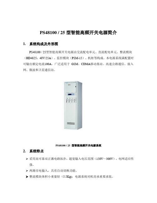
PS48100 / 25型智能高频开关电源简介1. 系统构成及外形图PS48100 / 25型智能高频开关电源由交流配电单元、直流配电单元、整流模块(HD4825:48V/25A)、监控模块(PSM-15)、机柜等构成。
本电源系统满配置时可输出额定电流100A。
广泛适用于GSM、CDMA移动基站、高速公路通信、接入网、微波和卫星通信站。
PS48100 / 25 型智能高频开关电源系统2. 系统特点➢采用高可靠双正激电路拓扑,超宽输入电压范围(150V~300V),电网适应性强。
➢两路市电输入,具有自动切换功能。
➢整流模块体积小重量轻(5.5Kg);电源系统对机房承重要求低。
➢采用国际安全标准EN60950;保证安全可靠运行。
➢超低辐射,达到最高环境等级要求;适用于居民区环境。
➢集散式监控,实时多任务(RTOS)操作系统。
提供多种通信接口;实现无人值守。
➢智能化电池管理和电池低电压保护,提高电池使用寿命保证网络安全。
➢低压差自主均流技术,不平衡度小于±3%;模块均分电流性能好。
➢具备电池仓,可放置48V100AH电池一组。
3. 电源系统技术参数3.1 电源系统交直流配电技术指标进/出线方式:交流上进线;直流上出线。
交流输入:单相三线制两路自动切换额定电流63A交流输出:单相3×16A(MCB)直流输出:2×100A(NT00) (电池熔丝)1×100A(NT00) (负载输出)1×50A(NT00)1×6A(NT00)1×63A(MCB)1×32A(MCB)2×16A(MCB)注:输出路数与容量可依用户需求适当调整电池保护:2×100A3.1 电源系统输出特性均充电压:- 56.5V浮充电压:- 53.5V输出直流电压可调节范围:- 42 ~- 58V系统均流:<±3%温度系数(1/℃):≤±0.2‰3.2 环境条件工作温度:-5~+45℃储存温度:-40~+85℃相对湿度:≤95%RH海拔高度:≤2000m3.3 机械特性4. 整流模块技术参数4.1 输入特性输入电压:150~300Vac输入电网频率:45~65Hz不工作承受最大静态电压:320V, 1小时效率:≥88%4.2 输出特性输出直流电压额定值:48V输出直流电压整定值:53.5V输出直流电压可调节范围:40 ~58V输出功率:1500W效率:≥90%输出电流:0~25A(最大为26A)负载调整率:≤±0.4%电网调整率:≤±0.1%输出限流特性:0%~50%~110%额定电流,三档可调温度系数(1/℃):≤±0.2‰峰-峰值杂音电压:≤100mV(0~20MHz)电话衡重杂音电压:≤1mV宽频杂音:≤50mV(3.4KHz~150KHz)≤20mV(0.15MHz~30MHz)离散杂音:≤5mV(3.4KHz~150KHz)≤3mV(150KHz~200KHz)≤2mV(200KHz~500KHz)≤1mV(0.5MHz~30MHz)音响杂音:≤55dB(A)4.3 保护特性短路保护:回缩电流<30%额定电流。
ETP48600用户手册

用于警示潜在的危险情形,若不避免,可能会导致中度 或轻微的人身伤害。
用于传递设备或环境安全警示信息,若不避免,可能会 导致设备损坏、数据丢失、设备性能降低或其它不可预 知的结果。
“注意”不涉及人身伤害。
文档版本 01
ii
ETP48600-D4A1 用户手册
符号
前言
说明 用于突出重要/关键信息、最佳实践和小窍门等。 “说明”不是安全警示信息,不涉及人身、设备及环境 伤害信息。
修订记录
修改记录累积了每次文档更新的说明。最新版本的文档包含以前所有文档版本的更新 内容。
文档版本 01 (2016-01-08)
第一次正式发布。
文档版本 01
iii
ETP48600-D4A1 用户手册
目录
目录
前 言................................................................................................................................................. ii
表32整流模块指示灯说明指示灯颜色状态说明电源指示灯绿色无交流输入整流模块内部损坏05hz闪烁人工查询状态4hz闪烁整流模块处于应用程序加载状态告警指示灯黄色环境温度过高引发的整流模块限功率预告警环境温度过高或过低保护关机告警交流输入过欠压保护整流模块休眠关机05hz闪烁整流模块与外部通讯中断故障指示灯红色整流模块无故障etp48600d4a1用户手册6系统调测文档版本0110指示灯颜色状态说明输出过压锁死整流模块内部故障引起的无输出34监控单元smu06c外观smu06c外观如图35所示
1 安全注意事项.................................................................................................................................. 1
IPS48100U 200U机架式控制器说明书(第一版)
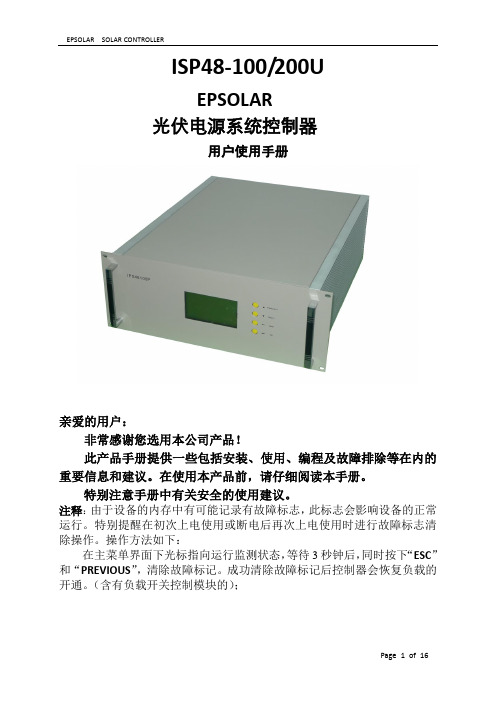
ISP48-100/200UEPSOLAR光伏电源系统控制器用户使用手册亲爱的用户:非常感谢您选用本公司产品!此产品手册提供一些包括安装、使用、编程及故障排除等在内的重要信息和建议。
在使用本产品前,请仔细阅读本手册。
特别注意手册中有关安全的使用建议。
注释:由于设备的内存中有可能记录有故障标志,此标志会影响设备的正常运行。
特别提醒在初次上电使用或断电后再次上电使用时进行故障标志清除操作。
操作方法如下:在主菜单界面下光标指向运行监测状态,等待3秒钟后,同时按下“ESC”和“PREVIOUS”,清除故障标记。
成功清除故障标记后控制器会恢复负载的开通。
(含有负载开关控制模块的);特别注意:1、本设备在与PC 机进行数据通讯时PC 机需要设置与之相对应的ID 号。
本台设备的ID 号为:此ID号已粘贴在设备的明显位置。
2、为了防止发生误操作,本设备的一些操作设置了密码。
输入密码的具体方法如下:在进入需要输入密码的操作界面之前会出现一个输入口令的界面,请按以下顺序按按键:▲ ,▼, ESC , ENTER , ESC ,ENTER。
设备验证口令正确后进入下一个界面。
连续3次输入密码错误,控制器则自动返回到主菜单,输入密码时间过长,如10分钟以上还没有输入完,也会自动返回到主菜单目录1. 概述 (1)2. 特点 (1)3. 参数表 (3)4. 控制器电器布置及结构框图 (4)4.1. DC配电端子 (5)4.2. I/O 信号输入输出板接线端子 (6)4.3. 机箱尺寸 (7)4.4. I PS48-100/200U控制器电气结构框图 (8)5. 控制器电气结构框图的描述 (9)5. 1. 充电控制 (9)5.2. 主控板 (9)5.3. 隔离接口板 (9)5.4. 图形式LCD 显示器及键盘 (9)5.5. 关于通讯 (9)5.6. 显示 (10)6. 安装 (11)7. 显示器及键盘操作说明 (12)1. 概述ISP48-100/200U控制器用于通讯光伏电源、独立光伏电站,以及光伏—柴油/汽油发电机或市电互补的混合电源系统供电控制和管理。
P6100_P8100_P4100详细用户手册
iii
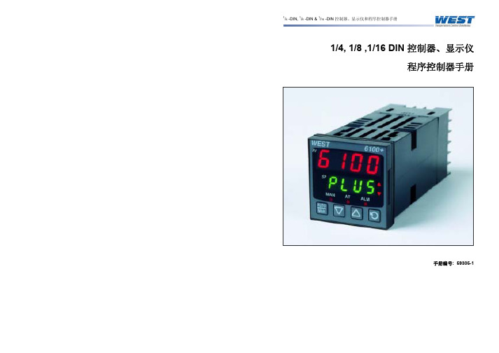
1/4 -DIN, 1/8 -DIN & 1/16 -DIN 控制器、显示仪和程序控制器手册
4.16 选件 A - RS485 通讯 ..................................................15
4.17 选件 A – 数字输入 .....................................................16
7.4 产品信息显示模式 .....................................................25
4.24 输出 2 – SSR 驱动.....................................................18
4.25 输出 2 – 固态继电器 ...................................................18
4.26 输出 2 – 线性直流 .....................................................19
4.21 输出 1 – 线性直流 .....................................................17
4.22 输出 2 - 继电器 ........................................................17
4.23 输出 2 – 双继电器 .....................................................18
5.1 上电步骤 .............................................................21
Omega PSP和PST系列电源供电器说明书
Shoponlineat:e-mail:**************INTRODUCTIONOMEGA®Power Supplies have outputs ranging from 5 to 28 volts, and from 40 mA to 500 mA (Refer to Tables 1 and 2). All styles feature excellent regulation and ripple parameters, and are short circuit protected. Rugged encapsulated construction and generously derated components insure years of reliable operation.Two case styles are available for your installation needs. The pin terminal style can either be soldered into a printed circuit board or plugged into a phenolic accessory socket board with gold plated Teflon insulated contacts. The barrier strip type case is designed to be mounted to a bulkhead or chassis using four 4-40 screws. FEATURESPin Terminal Style• No Derating or Heat Sinking Required• Short Circuit Protected• Small, Lightweight• Completely Sealed Case• Only 7 oz.Screw Terminal Style• 4-40 Screw Terminations and Mounting Inserts• Floating Output• Efficient• Rugged• 15 oz.OPERATING INSTRUCTIONSINPUT VOLTAGE:AC input models operate on 105-125 VAC, 47-420 Hz. (Models with an input of 210-250 VAC, 47420 Hz are available on special order).OUTPUT VOLTAGE ADJUSTMENT:Output(s) factory set to within +1% of the nominal output voltage rating. (AC input models having outputs of I to 9 volts, within 2%.) If necessary, outputs can be more precisely calibrated by the use of an external trim resistor connected between the T/C pin and one of the output pins. With certain units, connecting the resistor from the T/C pin to the (+) output pin increases voltage, and connecting to the (-) output pin decreases it; with other units, the reverse applies. Begin trimming with approximately 1 megohm resistance, and decrease resistance until calibration is attained. Do not use a resistance value of less than 20 K. Trimming the output to a voltage other than the nominal rating may adversely affect performance and may result in damaging the supply. SHORT CIRCUIT PROTECTION:All OMEGA miniaturized power supplies are of rugged construction and designed to withstand substantial overloads or short circuits for reasonable lengths of time. Prolonged operation under overloaded or shorted conditions is not recommended.COMMON POWER SUPPLY SPECIFICATIONSINPUT VOLTAGE:105-125 V ac, 47 to 420 Hz, single phase OUTPUT:See tables 1 and 2REGULATION:0.05% line, 0.05% load RIPPLE:0.5 mV rmsOUTPUT VOLTAGE TRIM ADJUSTMENT:Output is factory preset to ±2% (1 to 9 volt models) or ±1 1% (10 to 75 volt models) of nominal output voltage. Out put may be trimmed to the nominal voltage rating with an external trim resistor.POLARITY:Output is floating. Either positive or negative terminal may be grounded.AMBIENT OPERATING TEMPERATURE:- 20 to + 711 C. No derating required.STORAGE TEMPERATURE:-55 to +85°CTEMPERATURE COEFFICIENT:From 9 to 75 volts, approximate TC is015%/°C; 1 to 8 volts, .03%/°C IMPEDANCE:0.07 ohms at 1 kHz and 0.2 ohms at 10 kHz (approx.)DIMENSIONS:See Figures 1 and 2It is the policy of OMEGA Engineering, Inc. to comply with all worldwide safety and EMC/EMI regulations that apply. OMEGA is constantly pursuing certification of its products to the European New Approach Directives. OMEGA will add the CE mark to every appropriate device upon certification.The information contained in this document is believed to be correct, but OMEGA accepts no liability for any errors it contains, and reserves the right to alter specifications without notice.WARNING: These products are not designed for use in, and should not be used for, human applications.Direct all warranty and repair requests/inquiries to the OMEGA Customer Service Department. BEFORE RET URNING ANY PRODUCT (S) T O OMEGA, PURCHASER MUST OBT AIN AN AUT HORIZED RET URN (AR) NUMBER FROM OMEGA’S CUST OMER SERVICE DEPART MENT (IN ORDER T O AVOID PROCESSING DELAYS). T he assigned AR number should then be marked on the outside of the return package and on any correspondence.The purchaser is responsible for shipping charges, freight, insurance and proper packaging to prevent breakage in transit. FOR WARRANTY RETURNS, please have the following informa-tion available BEFORE contacting OMEGA:1.Purchase Order number under which the product was PURCHASED,2.Model and serial number of the product under warranty, and3.Repair instructions and/or specific problems relative to the product.FOR NON-WARRANTY REPAIRS,consult OMEGA for cur-rent repair charges. Have the following information avail-able BEFORE contacting OMEGA:1. Purchase Order number to cover the COST of the repair,2.Model and serial number of the product, and3.Repair instructions and/or specific problems relative to the product.OMEGA’s policy is to make running changes, not model changes, whenever an improvement is possible. This affords our customers the latest in technology and engineering.OMEGA is a registered trademark of OMEGA ENGINEERING, INC.© Copyright 2007 OMEGA ENGINEERING, INC. All rights reserved. T his document may not be copied, photocopied, reproduced, translated, or reduced to any electronic medium or machine-readable form, in whole or in part, without the prior written consent of OMEGA ENGINEERING, INC.Servicing North America:U.S.A.:One Omega Drive, Box 4047ISO 9001 Certified Stamford, CT 06907-0047Tel: (203) 359-1660FAX: (203) 359-7700e-mail:**************Canada:976 BergarLaval (Quebec) H7L 5A1, Canada Tel: (514) 856-6928FAX: (514) 856-6886e-mail:*************For immediate technical or application assistance:U.S.A. andSales Service: 1-800-826-6342/1-800-TC-OMEGA Canada:Customer Service: 1-800-622-2378/1-800-622-BEST Engineering Service: 1-800-872-9436/1-800-USA-WHEN Mexico:En Espan ˜ol: (001) 203-359-7803e-mail:*****************FAX: (001) 203-359-7807**************.mxServicing Europe:Czech Frystatska 184, 733 01 Karviná, Czech Republic Republic:TEL: +420 (0)59 6311899FAX: +420 (0)59 6311114Tol Free: 0800-1-66342e-mail:*****************Germany/Daimlerstrasse 26, D-75392 Deckenpfronn, Germany Austria:Tel: +49 (0)7056 9398-0FAX: +49 (0)7056 9398-29TollFreeinGermany************e-mail:*************United One Omega Drive, River Bend Technology Centre Kingdom:Northbank, Irlam, ManchesterISO 9002 Certified M44 5BD United KingdomTel: +44 (0)161 777 6611FAX: +44 (0)161 777 6622Toll Free in United Kingdom: 0800-488-488e-mail:**************.uk。
PSC100E24RP电源安装指南说明书

IL155006ENInstallation Instructions for PSC100E24RP POWER SUPPLYREAD INSTRUCTIONS BEFORE INSTALLING OR OPERATING THIS DEVICE. KEEP FOR FUTURE REFERENCE.1. Safety instructions • Switch main power off before connecting or disconnecting the device. Risk of explosion! • To guarantee sufficient convection cooling, keep a distance of > 40mm above and > 20mm below the device as well as a lateral distance of > 25mm to other cold source or heat source. • Note that the enclosure of the device can become very hot depending on the ambient temperature and load of the power supply. Risk of burns! Do not touch. • The main power must be turned off before connecting or disconnecting wires to the terminals! • Do not introduce any objects into the unit! • Dangerous voltage present for at least 5 minutes after disconnecting all sources of power. • The power supplies are built-in units and must be installed in a cabinet or room (condensation free environment and indoor location) that is relatively free of conductive contaminants. • The unit must be installed in an IP54 enclosure or cabinet in the final installation. • CAUTION: “FOR USE IN A CONTROLLED ENVIRONMENT”.2. Device description (Fig. 1) (1) Input terminal block connector (2) Output terminal block connector (3) DC voltage adjustment potentiometer (4) DC OK control LED (green) (5) Universal mounting rail system3. Mounting (Fig. 2) The power supply unit can be mounting on 35 mm DIN rails in accordance with EN 60715.The device should be installed with input terminal block on the bottom. Each device is delivered ready to install. Snap on the DIN rail as shown in Fig. 2: 1. Tilt the unit slightly upwards and put it onto the DIN rail. 2. Push downwards until stopped. 3. Press against the bottom front side for locking.4. Shake the unit slightly to ensure that it is secured. 4. Dismounting (Fig. 3) To uninstall, pull or slide down the latch as shown in Fig. 3. Then, slide the PSU in the opposite direction, release the latch and pull out the PSU from the rail.5. Connection The terminal block connectors allow easy and fast wiring. You can use flexible (stranded wire) or solid cables with cross sections 0.52-3.3mm² (AWG 20-12) and torque of 5.19Kgf-cm (4.5lb in). To secure reliable and shock proof connections, the stripping length should be 4-5mm (see Fig. 4 (1)). Please ensure that wires are fully inserted into the connecting terminals as shown in Fig. 4 (2). In accordance to EN 60950 / UL 60950 and EN 62368 / UL 62368, flexible cables require ferrules. Use appropriate copper cables designed to sustain operating temperature of: 1. 60°C, 60°C / 75°C for USA 2. At least 90°C for Canada. 5.1. Input connection (Fig. 1, Fig. 5) Use L and N connections of input terminal connector (see Fig. 1 (1)) to establish the 100-240 VAC connection. The unit is protected with internal fuse (not replaceable) at L pin and it has been tested and approved on 20A (UL) and 16A (IEC) branch circuits without additional protection device. An external protection device is only required if the supplying branch has an ampacity greater than above. Thus, if an external protective device is necessary, or, utilized, a minimum value of 20A B- or 10A C- characteristic breaker should be used. 5.2. Output connection (Fig. 1 (2)) Use the “+” and “-” screw connections to establish the 24 VDC connection. The output provides 24 VDC. The output voltage can be adjusted from 22 to 24 VDC on the potentiometer. The green LED DC OK displays correct function of the output (Fig. 1 (4)). The device has a short circuit and overload protection and an overvoltage protection limited to 30-34.8 VDC. 5.3. Output characteristic curve The device functions normal under operating line and load conditions. In the event of a short circuit or overload the output voltage and current collapses (I O/L or I S/C is >I surge (110-150%)). The secondary voltage is reduced and bounces until short circuit or overload on the secondary side has been removed. 5.4. Thermal behavior (Fig. 6). In the case of ambient temperatures: 1. At -10°C to -20°C, the output capacity has to be reduced by 2% per degree Celsius increase in temperature 2. Above +55°C, the output capacity has to be reduced by 3.33% per degree Celsius increase in temperature If the output capacity is not reduced when T Amb > 55°C, the device will run into thermal protection by switching off i.e. the output voltage will go into latch-off mode until the component temperature cools down and the AC power is recycled. FOR TECHNICAL ASSISTANCE CALL 1 - 877 - ETN - CAREIL155006ENTECHNICAL DATA FOR PSC100E24RPNominal input voltage / frequency100-240 VAC / 50-60 Hz Voltage range85-264 VAC Frequency47-63 Hz Nominal current< 1.2 A @ 115 VAC, < 0.6 A @ 230 VAC Inrush current limitation (+25°C, cold start)< 35 A @ 115 VAC, < 60 A @ 230 VAC Mains buffering at nominal load25 ms typ. @ 115 VAC, 50 ms typ. @ 230 VAC Turn-on time< 3 sec. @ 115 VAC, < 1.5 sec. @ 230 VAC Internal fuseT 3.15 A / 250 V Leakage current < 1 mA @ 240 VACNominal output voltage U N / tolerance 24 VDC ± 2 %Adjustment range of the voltage 22-24 VDC (maximum power ≤ 91.2W)Nominal current 3.8 ADerating Refer to Fig. 6 -10°C to -20°C (2% / °C), > 55°C (3.33 % / °C) in VerticalStartup with capacitive loads Max. 3,000 μFMax. power dissipation idling / nominal load approx. 0.4 W / 10 WEfficiency at 100% load 87.0% typ. @ 115 VAC, 89.0% typ. @ 230 VACPARD (20 MHz) at +25°C, 100% load < 75 mVppParallel operation PSG480R24RM / PSG960R24RM / With ORing DiodeType of housing Plastic (PC), enclosedLED Signals Green LED DC OKMTBF > 350,000 hrs.Dimensions (L x W x H) 75 mm x 45 mm x 100 mmWeight 0.325 kgConnection method Screw connectionStripping length 4-5 mmOperating temperature (surrounding air temperature) -20°C to +70°C (Refer to Fig. 6)Storage temperature -40°C to +85°CHumidity at +25°C, no condensation 5 to 95% RHVibration - Operating IEC60068-2-6,SineWave:*****************/s²;displacementof0.35mm,60min.per axis for all X, Y, Z directions - Non-Operating IEC60068-2-6, Random: 5Hz to 500Hz (2.09Grms); 20 min. per axis for all X, Y, Z directionsShock - Operating IEC60068-2-27, Half Sine Wave: 10G for a duration of 11ms, shock for 1 direction (X axis) - Non-Operating IEC60068-2-27, Half Sine Wave: 50G for a duration of 11ms, 3 shocks for each 3 directionsPollution degree 2Altitude (operating) 2000 MetersSafety entry low voltage SELV (EN 60950)Electrical safety (of information technology equipment) UL/C-UL recognized to UL60950-1 and CSA C22.2 No. 60950-1 UL/C-UL recognized to UL62368-1 and CSA C22.2 No. 62368-1Industrial control equipment UL/C-UL listed to UL 508 and CSA C22.2 No.107.1-01Class 2 Power Supply UL/C-UL listed to UL 508 and CSA C22.2 No.107.1-01CE In conformance with EMC directive 2014/30/EU and Low Voltage Directive 2014/35/EUComponent Power Supply for general use EN 61204-3Immunity EN 55024, EN 61000-6-1, EN 61000-6-2 (EN 61000-4-2, 3, 4, 5, 6, 8, 11)EmissionEN 55032, EN 55011, EN 61000-3-3, EN 61000-6-3, EN 61000-6-4RoHS Compliant YesSurge voltage protection against internal surge voltages NoIsolation voltage: Input / output Input / PE Output / PE 3 kVAC 3 kVAC 0.5 kVACProtection degree IP20Safety classClass I with PE connection© 2014 by Eaton Corporation All Rights ReservedPublication No. 10/19 IL155006EN October 2019Eaton Industries GmbH Hein-Moeller-Strabe 7-11, 53115 Bonn, Germany Eaton Corporation W126 N7250 Flint Drive Menomonee Falls, WI 53051, USA Contact your regional Eaton office for additional technical support /recycling Eaton is a registered trademark of Eaton Corporation. All other trademarks are property of their respective owners. www.eaton.eu/documentation Americas Eaton Corporation Electrical Sector +1.800.426.9184 North America 1-877-ETN-CARE /Customer_Support Europe – Middle East – Africa – Asia Pacific Eaton Industries GmbH Electrical Sector EMEA +49(0) 180 5 223822 (de, en) www.eaton.eu/aftersales www.eaton.eu/swd。
【最新整理】pgeps 系列应急电源产品说明书(含检验标准及日常注意事项)

EPS 系列应急电源(EPS)使用说明书概述1.说明➢EPS 系列消防应急电源输出纯正弦波,并带接触器式互投装置。
➢适用于各种照明、动力及混合型用电设备,如:电灯、电梯、风机、水泵、空调等设备的应急供电。
➢应用于高层建筑、人防设施、医院、机场、城市地铁、发电厂、大型商场、银行、证卷等场所,适用范围广,负载适应性强。
2.主回路原理图图13.工作原理➢EPS在交流电网供电正常时,由交流电网经过本设备的互投切换装置直接给负载供电,同时内置充电器给电池组进行智能充电。
➢当电网停止供电或电压低于15% 标称值时,本设备将立即自动切换到应急供电状态;由电池组经正弦波逆变,继续给负载提供纯净的正弦波交流电源。
➢当电网电压恢复正常后,本设备立即自动切换至电网供电。
4.电气特性充电机输入市电AC 220V±15%50Hz恒充电流5-10%C(A)C为单节电池容量恒充电压14.5×电池总数(V)±5%充电方式均充、浮充自动切换逆变器逆变电压AC 220V±5%50Hz输出波形正弦波过载能力Pn≤120%工作正常,Pn > 120%延时10秒停止切换时间< 5秒(特殊要求< 250ms )保护功能过载、短路、欠压等电池组电池种类铅酸免维护电池额定电压12V×电池总数备用时间90min充电时间< 24h电池组的安装1.说明➢以下安装说明以18节电池为例,其他数量的电池也类似;➢电池序号用数字加字符标示,即0、1、2 至9,A、B、C 至H;也就是从第10节电池开始用字符A、B、C等表示;➢电池循检线上的标签分别用B1、B2、B3至B19标示,或者是DX01、DX02、DX03至DX19标示;➢若拆卸或更换电池,也应遵守以下各注意事项;2.电池组安装图图63.安装步骤及注意事项a)电池组安装前请将机器的启动开关处在关闭状态,电池输入断路器处在断开位置;b)请确认电池循检线上的标签完整,保险座里有3A的保险管且完好;c)确认各电池的正负极,避免短路(一般电池的正端会标有红色标记,负端则用黑色标记);然后按图6中所示,从左到右依次固定各连接线与循检线;连线应避免拉紧,受力过大;电池循检线除B1(DX01)接在第1节电池的负端外,其他的都按图6所示,连同电池连接线一起,固定在相应的电池正端;d)无特殊说明,各电池按串联方式连接;即第1节的负端接上电池输入线的负端(黑线),第1节的正端接至第2节的负端,第2节的正端接至第3节的负端;依次类推,第17节(I#)的正端接至第18(H#)节的负端,第18(H#)节的正端接上电池输入线的正端(红线);e)机器工作在应急状态时,通常电池组会输出很大的电流,故须将各连接线的固定螺丝尽量拧紧;f)由于机器是金属外壳,为避免电池组短路,在安装过程中,电池连接线一端已经装到电池上,而另一端空置的必须缠绕绝缘胶布;液晶显示面板1.说明➢本说明以10KW单相液晶显示为例,其他型号可能略有变更,不再做详细说明;➢显示屏能显示的状态及故障有:市电状态外部输入市电直接旁路输出恒流充电充电机在恒定电流给电池组充电,约电池容量的0.1%A恒压充电充电机在恒定电压给电池组充电,约14.5V×电池数浮充充电机以约13.5V×电池数,给电池组充电逆变状态整机工作在电池组逆变输出应急输出开路逆变无反馈电压直流电压异常逆变时电池组欠压过载逆变输出过载应急模块报警功率模块过温/过流/欠压*#电池欠压第*号电池小于9.6V*#电池过压第*号电池大于15V2.显示屏面板图示图13.功能介绍➢指示灯:指示整机的工作状态,包括●主电:外部输入市电直接旁路输出●充电:市电给电池组充电●应急:应急状态电池组逆变输出●故障:整机工作出现故障➢翻屏/消音按钮:用以液晶屏翻页显示,以及在出现故障报警时用以消除声音,停止报警;图2 图3➢显示屏:显示整机状态、电池电压、状态列表及型号/名称●整机状态(如图1)包括输出/输入的电压和电流;如为三相EPS,由于在整机面板上有转换开关及电压表用以显示线电压,故液晶屏只显示B相的相电压;若在整机面板上已安装有电流表,则液晶屏将取消输出电流的显示;●电池电压(如图2)逐条显示电池组中各节电池的电压,以18节电池为例,分别用数字1-9加字符A-H表示各电池的序号;如显示“A#电池”表示的是第10节电池,“B#电池”为第11节电池,依次类推。
多功能225W AC to DC 开框电源说明书

MPOF225-20B15MPOF225-20B24MPOF225-20B27MPOF225-20B48225W AC to DC OpenFrame Power Supply /multicomp-pro/multicomp-proFeatures• Universal 85V AC to 264V AC or 120V DC to 370V DC input voltage• Compact size: 4” × 2” × 1”• Operating ambient temperature range: -40°C to +70°C• Active PFC• High I/O isolation test voltage up to 4000V AC• Operating altitude up to 5000m• Extremely low leakage current˂0.1mA• Stand-by power consumption˂0.3W• The base plate with conformal coating• Output short circuit, over-current, over-voltage, over-temperature protection• Suitable for BF application• Installing in system of Safety Class I/II is available• Safety according to IEC/EN/UL62368, IEC/EN60335, IEC/EN61558, GB4943, IEC/EN/ES60601 These series is one of AC-DC miniaturize open frame power supply and suitable for all kinds of BF type (be accessible to patients) medical system equipment. It features universal AC input and at the same time accepts DC input voltage, cost-effective, high efficiency, high reliability and double or reinforced insulation. These converters offer excellent EMC and safety performance, which meet IEC/EN/UL62368, GB4943, IEC/EN60335, IEC/EN61558, IEC/EN/ES60601 standards and they are widely used in areas of industrial, LED, street light control, electricity, security, telecommunications, smart home, medical, etc.Selection GuidePart Number Cool ModeOutput Power(W)Nominal Output Voltage and Current (Vo/Io)Output adj. Range (V)Efficiency at230VAC (%) Typ.Max. CapacitiveLoad (µF)MPOF225-20B12Air cooling14012V/11.67A11.8-12.6936000 13CFM22512V/18.75AMPOF225-20B15Air cooling14015V/9.33A14.7-15.85000 13CFM22515V/15AMPOF225-20B24Air cooling14024V/5.83A23.5-25.2943200 13CFM22524V/9.4AMPOF225-20B27Air cooling13027V/4.81A26.5-28.42400 13CFM22527V/8.35AMPOF225-20B48Air cooling14048V/2.91A47.1-50.41600 13CFM22548V/4.7ANote: Under any conditions, the total power of the product should not exceed the rated power of 225w and the output cur-rent should not exceed the rated output current.Input SpecificationsItem Operating Conditions Min.Typ.Max.UnitInput Voltage Range AC input85--264VAC DC input120--370VDCInput Frequency47--63HzInput Current 115VAC----3A 230VAC----2225W AC to DC Open Frame Power Supply/multicomp-pro /multicomp-proOutput SpecificationsItemOperating ConditionsMin.Typ.Max.UnitOutput Voltage Accuracy*Full load range--±1--%Line Regulation Rated load --±0.5--Load Regulation 0% - 100% load --±0.5--Ripple & Noise*20MHz bandwidth (peak-to-peak value)12V---60mV 15V/24V/27V/48V---100Temperature Coefficient --±0.03--%/°C Minimum Load 0----%Hold-up Time230VAC, 25°CAir cooling --16--ms 13CFM12Stand-by Power Consumption ----0.3W Short Circuit Protection Recovery time < 3s after the short circuit disappear.Hiccup, continuous, self-recovery Over-current Protection≥110%Io, hiccup, self-recovery Over-voltage Protection12V ≤16V (Output voltage turn off, re-power on for recover)15V≤20VDC (Output voltage turn off,re-power on for recover)24V ≤32V (Output voltage turn off, re-power on for recover)27V ≤35V (Output voltage turn off, re-power on for recover)48V≤60V (Output voltage turn off, re-power on for recover)Over-temperature ProtectionOutput voltage turn off, re-power on to recovery after abnormal removed Fan power15VOffer output power of 24V/0.25A with output voltage accuracy ±15%12V/24V/27V/48VOffer output power of 12V/0.5A with output voltage accuracy ±15%Note: 1. *Output voltage accuracy: including the setting error, line regulation, load regulation.2. *The “Tip and barrel method” is used for ripple and noise test, output parallel 10uF electrolytic capacitor and 0.1uF ceramic capacitor, please refer to AC-DC Converter Application Notes for specific information.3. *When the product works at light load (≤15% IO), in order to improve the efficiency to reach at green working mode, the value of ripple and noise will be double.4. *For all the above test items, please refer to our company standard “AC-DC Black Box Test Specification” for specific test specifications and methods.Inrush Current 115VAC Cold start --40--A230VAC --75--Power Factor 115VAC Full Load0.99------230VAC 0.95----Leakage Current 240VAC˂0.1mA; single failure˂0.5mAHot PlugUnavailable225W AC to DC OpenFrame Power Supply /multicomp-pro/multicomp-proGeneral SpecificationsItem Operating Conditions Min.Typ.Max.UnitIsolation Test Input - output Electric strength test for 1min., leakage current <10mA4000---VAC Input - 1500--Output - 1500--Insulation Resistance Input - Ambient temperature: 25 ± 5°CRelative humidity: < 95%RH, no condensationTest voltage: 500V DC50--MΩInput - output50--Output - 50--Isolation level Input - output2 × MOPP Input - 1 × MOPP Output - 1 × MOPPOperating Temperature-40-+70°CStorage Temperature-40+85Storage HumidityNon-condensing 1095%RHOperating Humidity2090Power Derating OperatingtemperaturederatingAir cooling+45°C to +70°C2--%/°C 13CFM+50°C to +70°C 2.5---40°C to -30°C2--Input voltage derating85VAC-115VAC Air cooling1%/VACSafety StandardMeetIEC/EN/UL62368-1/EN60335-1/IEC/EN61558-1/GB4943-1/IEC/EN60601-1/ ES60601-1(3.1 version)/CAN/CSA-C22.2 No.60601-1:14-Edition 3/ EN60601-1-2 Edition 4Safety Certification IEC/EN/UL62368-1/EN60335/ IEC61558(Pending)Safety Class CLASS I (with PE and must be connected)/CLASS II (without PE)MTBF MIL-HDBK-217F@25°C>300,000 h Warranty Ambient temperature: <50°C5 yearsMechanical SpecificationsCase Material Open frameDimensions101.6mm × 50.8mm × 25.4mmWeight 175g (Typ.)Cooling Method*Air cooling /13CFMNote: *Cooling method and power derating refer to typical characteristic curves.225W AC to DC Open Frame Power Supply/multicomp-pro /multicomp-proElectromagnetic Compatibility (EMC)Product Characteristic CurveEmissions*CECISPR32/EN55032 CLASS BRECISPR32/EN55032 (Category I, CLASS B, category II, CLASS A)Harmonic current IEC/EN61000-3-2 CLASS AImmunityESD IEC/EN 61000-4-2 Contact ±8KV/Air ±15KV Perf. Criteria A RS IEC/EN 61000-4-3 10V/m Perf. Criteria A EFTIEC/EN 61000-4-4 ±4KV Perf. Criteria A Surge IEC/EN 61000-4-5 ±2KV/±4KV Perf. Criteria A CSIEC/EN61000-4-6 10 Vr.m.sPerf. Criteria A Voltage dips, short interruptions and voltage variations immunityIEC/EN61000-4-11 0%, 70%perf. Criteria BNote: 1.*The power supply should be considered as a part of the components in the system. All EMC performance are been tested on a metal plate with a thickness of 1mm and a length of 360mm × 360mm. The power supply must be combined with the terminal equipment for electromagnetic compatibility confirmation;2.*Category I products with PE (Which must be connected), category II products without PE.MPOF225-20B24-C MPOF225-20B48-C MPOF225-20B12-CMPOF225-20B24-C MPOF225-20B48-C MPOF225-20B12-C225W AC to DC Open Frame Power Supply/multicomp-pro /multicomp-proImportant Notice : This data sheet and its contents (the “Information”) belong to the members of the AVNET group of companies (the “Group”) or are licensed to it. No licence is granted for the use of it other than for information purposes in connection with the products to which it relates. No licence of any intellectual property rights is granted. The Information is subject to change without notice and replaces all data sheets previously supplied. The Information supplied is believed to be accurate but the Group assumes no responsibility for its accuracy or completeness, any error in or omission from it or for any use made of it. Users of this data sheet should check for themselves the Information and the suitability of the products for their purpose and not make any assumptions based on information included or omitted. Liability for loss or damage resulting from any reliance on the Information or use of it (including liability resulting from negligence or where the Group was aware of the possibility of such loss or damage arising) is excluded. This will not operate to limit or restrict the Group’s liability for death or personal injury resulting from its negligence. Multicomp Pro is the registered trademark of Premier Farnell Limited 2019.Notes:1. U nless otherwise specified, parameters in this datasheet were measured under the conditions of Ta=25°C, humidity<75% with nominal input voltage and rated output load;2. All index testing methods in this datasheet are based on our company corporate standards;3. We can provide product customization service, please contact our technicians directly for specific information;4. Products are related to laws and regulations: see “Features” and “EMC”;5. O ur products shall be classified according to ISO14001 and related environmental laws and regulations, and shall be handled by qualified units;6. Warning: Use double fuses, please disconnect the power before maintenance and replacement;7. T he power supply is considered a component which will be installed into a terminal equipment. All EMC tests should be confirmed with the final equipment. Please consult our FAE for EMC test operation instructions.Dimensions and Recommended LayoutMPOF225-20B15MPOF225-20B24MPOF225-20B27MPOF225-20B48。
组合电源PS48100-225用户手册

用户手册资料版本E1-20020815-C-1.0BOM编码31010906艾默生网络能源有限公司为客户提供全方位的技术支持,用户可与就近的艾默生网络能源有限公司办事处或客户服务中心联系,也可直接与公司总部联系。
艾默生网络能源有限公司地址:深圳市龙岗区坂雪岗工业区华为基地电气厂房一楼、三楼公司网址:或客户服务热线:800-8302118E-mail:info@版权声明艾默生网络能源有限公司版权所有,保留一切权利。
在没有得到本公司书面许可时,任何单位和个人不得擅自摘抄、复制本书(软件等)的一部分或全部,不得以任何形式(包括资料和出版物)进行传播。
版权所有,侵权必究。
内容如有改动,恕不另行通知。
Copyright by Emerson Network Power Co., Ltd.All rights reserved.The information in this document is subject to change without notice. No part of this document may in any form or by any means (electronic, mechanical, micro-copying, photocopying, recording or otherwise) be reproduced, stored in a retrieval system or transmitted without prior written permission from Emerson Network Power Co., Ltd.出版说明内容介绍本手册介绍了PS48100-2/25智能高频开关电源系统的组成、安装、调测、日常使用维护及故障的应急处理。
读者对象本书适合下列人员阅读设备安装人员、设备维护人员安全注意事项在开始操作之前,请仔细阅读操作指示、注意事项,以减少意外的发生。
RUGGEDCOM RPS2410 600W 强壮型电源说明说明书

/rps2410/BRINGING THE EDGE TO LIFERUGGEDCOM RPS2410The increasing adoption of Power-over-Ethernet (PoE) in industrial IoT applications underlines the need for reliable and compact solutions to supply power at the edge. The RUGGEDCOM RPS2410 600 W rugged power supply is designed to meet the high- power demands of physical security, access control, wireless connectivity, lighting, and other PoE applications.The perfect companionUse the RUGGEDCOM RPS2410 1U rack-mount power supply to power the RUGGEDCOM RST2228P 19-inch rack PoE switch. The RUGGEDCOM RST2228P has 24 PoE ports delivering up to 60 W/port. Its high port density ensures PoE power management and connectivity to a large number of end devices such as PTZ cameras, wireless radio access points, VoIP phones, sensors, key-less access terminals, etc. It supplies sufficient power to prevent under-powering and overloading, increasing the safety and reliability of the entire network. The RUGGEDCOM RPS2410 with the RST2228P provides a small footprint, high-power PoE solution. It can be easily integrated into rack- or panel-mount assem-blies for low-profile installations and helps save on cabling, maintenance, and material costs. Power delivery across an operating temperature range of -40 °C to +75 °C and industrial approvals such as the NEMA TS 2 make this pair ideal for ITS networks and other industries experiencing harsh conditions.© Siemens 2021ReliableWide operating temperature range and fan-less design eliminate risk of mechanical failure. Parallel output operation for redundant power improves overall reliability FlexibleWide range of DC (150 – 250) and HI AC (120 – 240) inputs help avoid interme-diate power converters and additional capital expenditure Compact1U rack form-factor with standard mounting options supplying up to 600 W makes for a space-economizing network solution ScalableConnect up to three devices in parallel using the ISHARE feature, to supply up to 1560 W power EfficientDiagnostic LEDs for system health and failsafe relay output for remote alarm monitoring simplify troubleshooting in the fieldOrdering DataRUGGEDCOM RPS2410 600 W rack-mount power supply 6GK6000-8HS02-0AA0RUGGEDCOM RPS2410 600 W rack-mount power supply with conformal coating6GK6000-8HS02-0AA1Accessories: Mounting Kit for 19" rack- or panel-mounting, compatible with the RST2228, RST2228P, and RPS24106GK6000-8MA01-0AA0ParametersRUGGEDCOM RPS2410Electrical data/ InputSupply voltage (AC)Supply voltage (DC)120 V AC to 240 V AC 150 V DC to 250 V DC Design of input/wide input rangeYes Buffering time for rated value of the output current/in the event of power failure/minimum20 ms Current limitation/of inrush current/at 25 °C/max 25 A Fuse protection type/at input12 Electrical data/ OutputVoltage curve/at output 54 V DC Output current * rated value 11.1 ASupplied active power/max600 W (Standalone), 1080 W (Two devices), 1560 W (Three devices)Output power for different input voltages(Refer adja c ent Output power vs. Ambient tem-perature graphs)120 V AC input 600 W, -40 °C to +53 °C 240 V AC input 600 W, -40 °C to +67 °C,150 V DC input 600 W, -40 °C to +66 °C, 250 V DC input600 W, -40 °C to +69 °C, Ambient conditions Operating temperatureStorage temperature-40 °C to +75 °C -40 °C to +85 °C Protection ClassIP40Electrical interfaces Power supply1 x Input, 1 x Output,2 x ISHARESignaling contacts1 x NO, 1 x C, 1 x NC Relay OutputPhysical attributesDimensions (W x H x D) in mm Weight (approx.)440 x 51.5 x 267.52.8 kgFastening method19-inch rack and panel mounting Siemens AGProcess Industries and Drives Process Automation Postfach 48 4890026 Nürnberg, Germany Siemens Canada Limited 300Applewood Crescent Concord, Ontario, L4K 5C7 Canada© Siemens AG 2021Subject to change without prior notice Article No. 6ZB5531-0BC02-0BA0 Dispo 26000 BR1221 0 PoD 2 En Produced in GermanySubject to changes and errors. The information given in thisdocument only contains general descriptions and/or performance features which may not always specifically reflect those described, or which may undergo modification in the course of furtherdevelopment of the products. The requested performance features are binding only when they are expressly agreed upon in the concluded contract.All product designations may be trademarks or product names of S iemens AG or supplier com p anies whose use by third parties for their own purposes could violate the rights of the owners.Security informationIn order to protect plants, systems, machines and networks against cyber threats, it is necessary to implement – and continuously maintain – a holistic, state-of-the-art industrial security concept. Siemens’ products and solutions constitute one element of such a concept. For additional information on industrial security measures that may be imple-mented, please visit:/industrialsecurity/rps2410/0100200300400500600700-40-20+20+40+51+53+55+57+59+61+63+65+67+69+71+73+75+77O u t p u t p o w e r (W )Ambient Temperature °CInput voltage V in = 120V ACPower derating gradient = 22.4W/°C = 22.4W/K 0100200300400500600700-40-30-20-10+10+20+30+40+50+60+67+68+69+70+71+72+73+74+75+76O u t p u t p o w e r (W )Ambient Temperature °CInput voltage V in = 240V ACPower derating gradient = 62.2W/°C = 62.2W/K100200300400500600700-40-30-20-100+10+20+30+40+50+60+66+67+68+69+70+71+72+73+74+75+76+77O u t p u t p o w e r (W )Ambient Temperature °CInput voltage V in = 150V DCPower derating gradient = 50.9W/°C = 50.9W/K100200300400500600700-40-30-20-10+10+20+30+40+50+60+69+70+71+72+73+74+75+76+77O u t p u t p o w e r (W )Ambient Temperature °CInput voltage V in = 250V DCPower derating gradient = 70W/°C = 70W/KOutput power vs. ambient temperature Air flow 0.27 m/s (400 cfm)ISHARE120 – 240 V AC or 150 – 250 V DC Fail-safe relay output 54 DCG _R C M 0_X X _0046512 / 24 / 48 / HI V DC or V ACPowering PoE loads exclusively,600 W max Powering switch and PoE loads,600 W max Dual configuration for HI power operation – 1080 W max Three supplies in redundant configuration – 1560 W max。
艾默生电源维护手册(修改版)
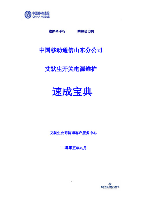
1维护牵手行 共织动力网中国移动通信山东分公司艾默生开关电源维护速成宝典艾默生公司济南客户服务中心二零零五年九月2序 言中国移动通信责任有限公司山东分公司是艾默生网络能源有限公司极其重要客户和伙伴。
目前,山东移动网上运行的艾默生智能开关电源(包括前华为开关电源)共2800余套,其中,电源大部分型号集中分布如下:八期建设的由NP9801监控单元构成的PS48300-2/50,PS48450-2/50系统;九期建设的由PSM-A 构成的PS48400-2/50,PS48600-2/50系统;十期建设的PS48400-2B/50系统;十一期建设的的PS48400-2C/50系统;同时十二期正在建设中的基站电源也集中在由M500F 监控单元所组成的PS48400-3/2900和PS48600-3/2900系统。
此外,在早期基站中,还有部分由PSM-15组成的PS48100/25,PS48300/25,PS48120/20,PS48240/20系统。
以上型号的电源占到了目前总量的90%以上。
为了进一步加强山东省移动公司基层的维护技术力量,帮助贵公司提升网络质量,打造GSM 精品网络,共同提高移动公司市场竞争力,艾默生济南客户服务中心特组织精兵强将,以移动公司相对集中设备型号,编写了该维护手册。
本手册不仅包含了日常维护中80%以上的设备运行问题,同时,还介绍了电源日常保养、巡检和电源安装工程的内容和规范。
我们期待此手册能达到我们预期的目的,希望我们的服务能为贵公司在严峻的竞争中尽绵薄之力。
由于笔者水平有限,也恳请贵公司领导和同行们多指教!31`第一篇:由NP9801构成系统日常维护指南(PS48300-2/50,PS48450-2/50)...................................................................................................................................... 1问一:由NP9801监控单元组成系统的结构与配置情况? ............................................... 1 问二:如果机房无三相电或有缺相时,电源的交流引入线如何连接? ......................... 1 问三:整流模块前面板拨码开关是什么含义,如何设置? ............................................. 2 问四:模块地址如何设置? ................................................................................................. 2 问五:在更换该系统的整流模块时,有何注意事项,正确步骤? ................................. 2 问六:有时在开启模块输入空开后,模块打火或者后面开始冒烟?何故?如何处理? ................................................................................................................................................ 3 问七:当系统中其中一个模块无输出电流时,如何判断其好坏? ................................. 3 问八:模块间是否均流的判断标准是什么?当整流模块不均流时,如何调节? ......... 3 问九:为什么有时拆除一台整流模块,其他整流模块同时出现通信中断故障? ......... 4 问十:系统中单个模块通信中断,通常由那些因素造成,如何处理? ......................... 4 问十一:监控单元密码是多少?分别有什么用? ............................................................. 4 问十二:对于NP9801监控单元组成的系统,如何正确进行系统配置? ....................... 4 问十三:监控单元有集中复位方式? ................................................................................. 5 问十四:监控模块内需要设置的电池参数有哪些? ......................................................... 5 问十五:对于电池组数的设置,如果系统只有一组电池应该如何连接,监控模块如何设置?......................................................................................................................................... 5 问十六:忘记用户级密码如何处理? ................................................................................. 5 问十七:防雷器部分如何维护? ......................................................................................... 5 附录:NP9801监控单元内目录结构如下: ........................................................................ 6 第二篇:由PSM-A 构成系统维护指南(含PS48400-2/50,PS48600-2/50) ... 7问一:使用PSM-A 监控单元的型号有哪些? ..................................................................... 7 问二:交流接触器不吸合? ................................................................................................. 7 问三:交流接触器频繁跳动(吸合后随即断开)? ......................................................... 7 问四:交流防雷器故障告警? ............................................................................................. 7 问五:交直流通信异常? ..................................................................................................... 7 问六:交流电压正常,模块工作正常,但是负载不能够工作? ..................................... 8 问七:监控单元显示直流电流或电池电流与模块输出显示电流偏差很大? ................. 8 问八:负载熔丝断误告警? ................................................................................................. 8 问九:模块通信中断故障如何判断?如何处理? ............................................................. 8 问十:模块有输出电压,但没有输出电流? ..................................................................... 9 问十一:监控单元没有显示? ............................................................................................. 9 问十二:更换监控单元需要设置的数据? ......................................................................... 9 第三篇:PS48400-2B/50,PS48400-2C/50电源系统维护指南......................... 11问一:通常艾默生开关电源都由哪几部分组成? ......................................................... 11 问二:PS48400-2B/50系统交流配电部分由哪些部件组成? ...................................... 11 问三:移动十一期基站使用的PS48400-2C/50系统与十期基站的PS48400-2B/50系统有2何区别?在维护的时候有什么区别? ............................................................................. 11 问四:有哪些常见的交、直流保护参数?参照值为多大? ......................................... 11 问五:PS48400-2B/50系统的工作原理? ...................................................................... 12 问六:直流配电的基本特点? ......................................................................................... 12 问七:如果交流接触器不吸和,如何判断交流接触器的好坏?如何采取应急措施? . 13问八:常见的模块故障有哪些,可能原因分析。
- 1、下载文档前请自行甄别文档内容的完整性,平台不提供额外的编辑、内容补充、找答案等附加服务。
- 2、"仅部分预览"的文档,不可在线预览部分如存在完整性等问题,可反馈申请退款(可完整预览的文档不适用该条件!)。
- 3、如文档侵犯您的权益,请联系客服反馈,我们会尽快为您处理(人工客服工作时间:9:00-18:30)。
用户手册资料版本E1-20020815-C-1.0BOM编码31010906艾默生网络能源有限公司为客户提供全方位的技术支持,用户可与就近的艾默生网络能源有限公司办事处或客户服务中心联系,也可直接与公司总部联系。
艾默生网络能源有限公司地址:深圳市龙岗区坂雪岗工业区华为基地电气厂房一楼、三楼公司网址:或客户服务热线:800-8302118E-mail:info@版权声明艾默生网络能源有限公司版权所有,保留一切权利。
在没有得到本公司书面许可时,任何单位和个人不得擅自摘抄、复制本书(软件等)的一部分或全部,不得以任何形式(包括资料和出版物)进行传播。
版权所有,侵权必究。
内容如有改动,恕不另行通知。
Copyright by Emerson Network Power Co., Ltd.All rights reserved.The information in this document is subject to change without notice. No part of this document may in any form or by any means (electronic, mechanical, micro-copying, photocopying, recording or otherwise) be reproduced, stored in a retrieval system or transmitted without prior written permission from Emerson Network Power Co., Ltd.出版说明内容介绍本手册介绍了PS48100-2/25智能高频开关电源系统的组成、安装、调测、日常使用维护及故障的应急处理。
读者对象本书适合下列人员阅读设备安装人员、设备维护人员安全注意事项在开始操作之前,请仔细阅读操作指示、注意事项,以减少意外的发生。
产品及产品手册中的"小心、注意、警告、危险"事项,并不代表所应遵守的所有安全事项,只作为各种操作安全注意事项的补充。
因此,负责产品安装、操作的人员必须经严格培训,掌握系统正确的操作方法及各种安全注意事项后方可进行设备的各项操作。
在进行本公司产品、设备的各项操作时,必须遵守相关行业的安全规范,严格遵守本手册提供的相关设备注意事项和特殊安全指示。
电气安全一、高压本电源系统运行时部分部件带有高压,直接接触或通过潮湿物体间接接触这些部件,会带来致命的危险。
交流电源设备的安装,必须遵守相关行业的安全规范,进行交流设备安装的人员,必须具有高压、交流电等作业资格。
操作时严禁在手腕上佩带手表、手链、手镯、戒指等易导电物体。
发现机柜有水或潮湿时,请立刻关闭电源。
在潮湿的环境下操作时,应严格防止水分进入设备。
安装过程中不能容许操作的开关和按扭上,必须挂上禁止标识牌。
高压线路的施工操作,可能导致起火或电击意外。
交流电缆的架接、走线经过区域必须遵循所在地的法规和规范。
只有具有高压、交流电作业资格的人员才能进行各项高压操作。
二、工具在进行高压、交流电各种操作时,必需使用专用工具,不得使用普通或自行携带的工具三、雷雨严禁在雷雨天气下进行高压、交流电,及铁塔、桅杆作业在雷雨天气下,大气中会产生强电磁场。
因此,为避免雷击损坏设备,要及时做好设备的良好接地。
四、静电人体产生的静电会损坏电路板上的静电敏感元器件,如大规模集成电路(IC)等。
在接触设备,手拿插板、电路板、IC芯片等前,为防止人体静电损坏敏感元器件,必须佩戴防静电手腕,并将防静电手腕的另一端良好接地五、短路严禁操作时将电源系统直流配电正负极短路或将非接地极对地短路。
电源设备为恒压直流供电设备,短路将会引起设备烧毁和人身安全危害。
在进行直流带电作业时必须严格检查线缆和接口端子的极性。
直流配电操作空间紧凑,任何操作之前要注意选好操作空间。
操作时严禁在手腕上佩带手表、手链、手镯、戒指等易导电物体。
操作必须使用绝缘工具。
带电操作时,必须注意手、腕、臂保持紧张状态,使得发生工具卡接脱落时,人体和工具的自由行程最小。
电池进行电池作业之前,必须仔细阅读电池搬运的安全注意事项,以及电池的准确连接方法。
电池的不规范操作会造成危险。
操作中必须严格注意、小心防范电池短路或电解液溢出、流失。
电解液的溢出会对设备构成潜在性的威胁,会腐蚀金属物体及电路板,造成设备损坏及电路板短路。
电池安装、操作前,为确保安全,应注意如下事项:* 摘下手腕上的手表、手链、手镯、戒指等含有金属的物体。
* 使用专用绝缘工具。
* 使用眼睛保护装置,并做好预防措施。
* 使用橡胶手套,佩戴好预防电解液溢出的围裙。
* 电池在搬运过程中应始终保持电极正面向上,严禁倒置、倾斜。
其他一、安规要求在更换监控模块和配电单元的信号转接板W2442X1的工作电源输入保险丝时,必须采用同型号的保险丝F5AL250V,以符合安规要求二、物体尖角用手搬运设备时,要佩带保护手套,防止利物割伤三、电源电缆在连接电缆之前,确认电缆及电缆标签与实际安装是否相符四、信号线的绑扎信号线应与强电流或高压线分开绑扎,绑扎的间距至少为150mm。
目录第一章系统概述 11.1 系统简介 11.1.1 PS48100-2/25系统结构图11.1.2 PS48100-2/25系统配置表31.1.3 系统的主要特点 31.2 各组成部分简介 51.2.1 整流模块 51.2.2 监控模块71.2.3 DC/DC模块101.2.4 交直流配电141.2.5 艾默生电池20第二章安装准备252.1 电源设备安装基本要求252.1.1 机房的环境要求252.1.2 机房的布置要求262.1.3 供电要求292.1.4 安全防护要求292.2 安装的准备工作322.2.1 现场检查322.2.2 工具与材料准备322.3 开箱验货34第三章设备安装353.1 机柜安装353.1.1 直接在地板上安装353.1.2 在支架上安装373.2 整机组装393.2.1 整流模块安装393.2.2 监控模块安装403.2.3 DC/DC变换器的安装403.2.4 电池安装403.3 电力线的连接403.3.1 电力线的连接方式要求403.3.2 交流电力线的连接423.3.3 直流电力线的连接433.3.4 地线安装473.4 MODEM的安装473.4.1 MODEM的安装与接线473.4.2 MODEM配置及其它493.5 温度传感器电缆的安装49第四章系统调测504.1 系统复位514.2 交流上电514.3 整流模块上电524.4 监控模块上电524.5 配电开关调测534.6 电池的接入534.7 负载设备的接入54第五章监控模块使用说明555.1 监控模块的菜单结构555.2 操作说明565.3 系统运行信息屏565.4 模块信息屏575.5 系统当前告警和历史告警信息屏58 5.6 系统输出控制屏595.7 系统参数设置615.7.1 设置电池管理参数615.7.2 其它参数设置625.8 系统初始化设置625.8.1 系统类型选择635.8.2 监控模块语言设置645.8.3 密码重置645.8.4 系统重置645.9 干节点输出64第六章设备的日常维护和检查666.1 风扇和防尘网的检修666.2 整流模块和系统熔芯的更换676.3 增加负载676.4 模块扩容676.5 电源系统的巡检指导686.6 应急处理726.6.1 交流配电应急处理726.6.2 直流配电应急处理726.6.3 监控系统故障应急处理736.6.4 整流模块故障应急处理736.6.5 停电746.6.6 灾变事故74附录A系统的技术参数75附录B PS48100-2A/25控制系统原理图 79附录C PS48100-2B/25控制系统原理图80附录D PS48100-2C/25控制系统原理图 81附录E PS48100-2A/25系统接线图82附录F PS48100-2B/25系统接线图83附录G PS48100-2C/25系统接线图 84附录H 告警信息列表85第一章系统概述1.1 系统简介PS48100-2/25智能高频开关电源系统是艾默生网络能源有限公司集多年开发和网上运行经验设计的新一代高可靠、高性能的通信电源系统,这个系统有三种配线机柜构成:一个为二路交流输入手动机械控制机柜;一个为二路交流输入自动切换控制机柜;一个为二路交流输入手动机械控制电池机柜。
它们的型号分别为:PS48100-2A/25,PS48100-2B/25,和PS48100-2C/25。
PS48100-2A/25的系统配置:交直流配电单元(手动)、整流模块HD4825-3、监控模块PSM-A10、电池柜。
PS48100-2B/25的系统配置:交直流配电单元(自动)、整流模块HD4825-3、监控模块PSM-A10、DC/DC 模块DPC48-3、电池柜和用户交流输出插座。
PS48100-2C/25的系统配置:交直流配电单元(手动)、整流模块HD4825-3、监控模块PSM-A10、艾默生专用电池。
PS48100-2/25表示所描述的内容适用于PS48100-2A/25、PS48100-2B/25和PS48100-2C/25三套系统。
根据用户的需要可以选配不同的电源系统,PS48100-2/25的结构图见图1-1所示(三个系统的外观结构图一致)。
1.1.1 PS48100-2/25系统结构图PS48100-2/25系统的结构图如图1-1所示。
1.运行指示灯2.故障指示灯3.交直流配电单元4.监控模块5.整流模块(2~4个)6.DC/DC模块或假面板7.第一层电池柜8.第二层电池柜9.第三层电池柜10.通风盖板图1-1 PS48100-2/25系统结构示意图PS48100-2/25系统机械参数系统类别体积(高×宽×深)(mm×mm×mm)重量(kg)PS48100-2/25 电源系统2000mm×600mm×600mm135kg机柜重量为无配置时的重量(不包括整流模块、监控模块和DC/DC模块,和"艾默生电池")。
1.1.2 PS48100-2/25系统配置表PS48100-2/25系统配置见下表。
PS48100-2/25系统配置表标准配置最大配置最小配置可选配置备注监控模块PSM-A10111必配整流模块HD4825-3442数量可选DC/DC模块DPC48-310或1仅适用PS48100-2B/25直流配电输出路数710(正面)/非标可选交流输入路数222/配线柜手动切换适用PS48100-2A/25PS48100-2C/25自动切换适用PS48100-2B/25电池组件222必配适用PS48100-2C/25,其它两套系统不包括此组件备注:电池组件包括电池、电缆、和酸雾盒等附件,电池为"艾默生电池"。
