VCS 1281,219
飞思卡尔MC9S12XS128单片机各模块使用方法及寄存器配置

飞思卡尔MC9S12XS128单片机各模块使用方法及寄存器配置手把手教你写S12XS128程序--PWM模块介绍该教程以MC9S12XS128单片机为核心进行讲解,全面阐释该16位单片机资源。
本文为第一讲,开始介绍该MCU的PWM模块。
PWM 调制波有8个输出通道,每一个输出通道都可以独立的进行输出。
每一个输出通道都有一个精确的计数器(计算脉冲的个数),一个周期控制寄存器和两个可供选择的时钟源。
每一个P WM 输出通道都能调制出占空比从0—100% 变化的波形。
PWM 的主要特点有:1、它有8个独立的输出通道,并且通过编程可控制其输出波形的周期。
2、每一个输出通道都有一个精确的计数器。
3、每一个通道的P WM 输出使能都可以由编程来控制。
4、PWM 输出波形的翻转控制可以通过编程来实现。
5、周期和脉宽可以被双缓冲。
当通道关闭或PWM 计数器为0时,改变周期和脉宽才起作用。
6、8 字节或16 字节的通道协议。
7、有4个时钟源可供选择(A、SA、B、SB),他们提供了一个宽范围的时钟频率。
8、通过编程可以实现希望的时钟周期。
9、具有遇到紧急情况关闭程序的功能。
10、每一个通道都可以通过编程实现左对齐输出还是居中对齐输出。
1、PWM启动寄存器PWMEPWME 寄存器每一位如图1所示:复位默认值:0000 0000B图1 PWME 寄存器每一个PWM 的输出通道都有一个使能位P WMEx 。
它相当于一个开关,用来启动和关闭相应通道的PWM 波形输出。
当任意的P WMEx 位置1,则相关的P WM 输出通道就立刻可用。
用法:PWME7=1 --- 通道7 可对外输出波形PWME7=0 --- 通道7 不能对外输出波形注意:在通道使能后所输出的第一个波形可能是不规则的。
当输出通道工作在串联模式时(PWMCTL 寄存器中的CONxx置1),那么)使能相应的16位PWM 输出通道是由PWMEx 的高位控制的,例如:设置PWMCTL_CON01 = 1,通道0、1级联,形成一个16位PWM 通道,由通道 1 的使能位控制PWM 的输出。
自动巡线小车的图像采集系统开发与优化
37542010,31(17)计算机工程与设计Computer Engineering and Design0引言自动巡线小车是智能自动化控制研究领域的一项重要内容。
作为一门新兴的综合技术,自动巡线小车可广泛地应用于工厂自动料车、固定场地搬运车等技术领域,但它要到达人们设想的高度智能化还有很长的距离。
近年来,出现了越来越多的基于DSP 、FPGA 等高速处理器的图像采集系统,主要用于运算量大的实时处理算法的实现[1]。
但这些高速图像采集系统并不适合于中低速单片机控制平台,且它们均采用分离元件实现采集控制电路,如产生视频缓冲存储器的地址、锁相环路的分频,视频的A/D 转换,采集控制,数字信号处理器,电路设计复杂,成本高而且不便于调试[2]。
所以,为了适应智能车竞赛的开发平台,利用低功耗的CMOS 数字摄像头OV6620,开发了以飞思卡尔MC9S12XS128微控制器为主控芯片的图像采集系统,采用IDT 公司的双口静态FIFO 存储器IDT7008作为缓冲存储器,将信号完整地采集进系统,实现对系统的优化。
为了在不牺牲系统的运行速度的前提下,引入分割最佳阀值的迭代算法和中值滤波快速算法,以达到边缘检测的精确定位和更好的消除随机噪声的干扰。
该系统的开发是基于在白色背景上有一条任意给定的黑色带状引导线的场地。
1图像采集系统的硬件组成该图像采集系统主要是由低功耗的CMOS 数字摄像头OV6620和飞思卡尔MC9S12XS128微控制器组成,并考虑到单片机的MC9S12XS128读取速度比摄像头OV6620输出速率收稿日期:2009-10-21;修订日期:2009-12-21。
嵌入式系统工程张璐,宋秋红:自动巡线小车的图像采集系统开发与优化2010,31(17)3755慢,使用高速、低功耗异步的双口静态存储器IDT7008进行数据缓存,实现系统的优化。
摄像头OV6620是CMOS的数字摄像头,具有功耗低、集成度高,便于采用高速的并行读取体系等优点,它以隔行扫描的方式采集图像上的点,它需要稳定的5V电压供电,可和单片机电源共用,PAL制,灰度等级为256级,每秒25帧,一帧两场,那么每秒就有50场,意味着20ms就有一幅图像产生,356x292pixels,即一幅图像有292行,一行有356个点。
VCS Lab Guide自学笔记——快速入门VCS

VCS Lab Guide自学笔记——快速入门VCSfrom Monchy(蒙奇)在2020年秋招前根据Synopsys的VCS Lab Guide自学如何VCS(verilog compiled simulation)工具,在此分享前三章详细的学习笔记,几乎是指南的中文翻译,大量的过程截图对初学者很友好。
(VCS Lab Guide是Synopsys给出的VCS官方入门指南,里面包涵源码和实验指导,可以在网上自行下载)1VCS Simulation Basics用VCS编译和仿真8位进位选择加法器的Verilog设计Lab1实验使用8位进位选择加法器。
各模块代码:1fa.v(带进位的一位加法器)2add4.v(带进位4位加法器)3add8.v(8位加法器)4addertb.v(测试平台)代码所在位置如图:Part A:两步仿真过程Task1:用VCS编译verilog源码,生成可执行文件.simvshell>vcs addertb.v fa.v add4.v add8.v如果编译后在终端看到waning,最好先把warning解决了。
Task2:运行testbench,通过simv文件仿真设计shell>./simv如果想要直接通过名字执行必须要先在.bashrc文件中设置。
实际指令是“./simv”,如果没有加“./”刚开始是认不到到。
所以在“.bashrc”文件中加入"export PATH=$PATH:."。
相当与把“./”加入到了PATH中,样再输入“simv”就可以认到了。
具体加到哪我不知道。
task3:使用-o开关重命名可执行文件vcs编译生成的可执行文件的名默认为simv,如果想要改名字需要使用-o开关。
在终端输入下列命令,可以修改simv名字为addertest。
shell>vcs addertb.v fa.v add4.v add8.vPart B:在不同的程序目录下仿真Task1:使用设计库目录编译并仿真addertb.v和add8.v位于/lab1/partb目录下,fa.v和add4.v位于lib库目录内。
三极管参数表

|常用三极管参数表下表是常用三极管的一些参数以及替换型号器件型号电压电流代换型号3DG9011 50V 2N4124 CS9011 JE9011 9011 50V LM9011 SS90119012 40V LM90129012(HH) 40V SS90129012LT1 40V A12983DG9013 40V CS9013 JE9013&9013 40V LM90139013(HH) 40V SS90139013LT1 40V C32653DG9014 50V CS9014 JE90149014 50V LM9014 SS90149014LT1 50V C16239015 50V LM9015 SS9015TEC9015 50V BC557 2N3906TEC9015A 50V BC557 2N3906TEC9015B 50V BC557 2N3906[TEC9015C 50V BC557 2N39063DG9016 30V JE90169016 30V SS9016TEC9016 40V BF240 BF254 BF5948050 40V SS80508050LT1 40V KA3265ED8050 50V BC337SDT85501 60V 10A 3DK104CSDT85502 80V 10A 3DK104CSDT85503 100V 10A 3DK104D~SDT85504 140V 10A 3DK104ESDT85505 170V 10A 3DK104FSDT85506 60V 10A 3DK104CSDT85507 80V 10A 3DK104CSDT85508 100V 10A 3DK104DSDT85509 140V 10A 3DK104EED8550 50V BC3378550 40V LM8550 SS85508550LT1 40V KA32652SA1015 50V BC177 BC204 BC212 BC213 BC251 BC257 BC307 BC512 BC557 CG1015 CG673 ¥2SC1815 60V BC174 BC182 BC184 BC190 BC384 BC414 BC546 DG458 DG18152SC1815L 60V BC550 2SC2240 2S26742SC2675 2SC33782SC1815LT1 60V 9014LT12SC945 60V BC107 BC171 BC174 BC182 BC183 BC190 BC207 BC237 BC382 BC546 BC547 BC582 DG945 2N2220 2N2221 2N2222 3DG120B 3DG4312 MMBT3904 40V BCW72 3DG120CMMBT3906 40V BCW70 3DG120CMMBT2222 未知BCX19 3DG120CMMBT2222A 75V 3DK10CMMBT5401 160V 3CA3FMMBTA92 300V 3CG180H'BC807 50V BC338 BC537 BC635 3DK14B BC807R 50V BCX17 BCX17R BCW68BCW68RBC807-W 50V BCX17 BCW68 2SB1219ABC817 50V BCX19 BCW65 BCX66BC817R 50V BCX19 BCX19R BCW65BCW65R BCX66 BCW66RBC817-W 50V BCX19 BCW65 BCW66 2SD1820 2SD1949BC846 80V BCV71 BCV72BC846R 80V BCV71 BCV71R BCV72 BCV72R BC846-W 80V BCV71 BCV72 BCV72RBC847 50V BCW71 BCW72 BCW81《BC847R 50V BCW71 BCW71R BCW72 BCW72R BCW81 BCW81RBC847-W 50V BCW71 BCW72 BCW812SC4101 2SC4102BC848 30V BCW31 BCW32 BCW33 BCW71 BCW72 BCW81BC848R 30V BCW31 BCW31R BCW32 BCW32R BCW33 BCW33R BCW71 BCW71R BCW72 BCW72R BCW81 BCW81RBC848-W 30V BCW31 BCW32 BCW33 BCW71 BCW72 BCW81 2SC4101 2SC4102 2SC4117BC856 50V BCW89BC856R 80V BCW89 BCW89RBC856-W 80V BCW89 2SA1507 2SA1527BC857 50V BCW69 BCW70 BCW89BC857R 50V BCW69 BCW69R BCW70 BCW70R BCW89 BCW89R(BC857-W 50V BCW69 BCW70 BCW892SA1507 2SA1527BC858 30V BCW29 BCW30 BCW69 BCW70 BCW89BC858R 30V BCW29 BCW29R BCW30 BCW30R BCW69 BCW69R BCW70 BCW70R BCW89 BCW89RBC858-W 30V BCW29 BCW30 BCW69 BCW70 BCW89 2SA1507 2SA15272SA733 60V BC177 BC204 BC212 BC213 BC251 BC257 BC307 BC513 BC557 3CG120C 3CG4312 MMUN2111 50V UN2111MUN2111 50V MMUN2111UN2111 50V FN1A4M DTA114EK RN24022SA1344MMUN2112 50V UN2112MUN2112 50V MMUN2112—UN2112 50V FN1F4M DTA124EK RN24032SA1342MMUN2113 50V UN2113MUN2113 50V MMUN2113UN2113 50V FN1L4M DTA144EK RN24042SA1341MMUN2211 50V UN2211MUN2211 50V MMUN2211UN2211 50V DTC114EK FA1A4M RN14022SC3398MMUN2212 50V UN2212MUN2212 50V MMUN2212UN2212 50V DTC124EK FA1F4M RN14032SC3396、MMUN2213 50V UN2213MUN2213 50V MMUN2213UN2213 50V DTC144EK FA1L4M RN14042SC33952SC3356 20V 2SC3513 2SC3606 2SC38292SC3838K 30V BF517 BF799 2SC3015 2SC3016彩显中易损大功率三极管主要参数表型号功率(W) 反压(V) 电流(A) 功能BU208A 50 1500 5 电源开关管BU508A 75 1500 8 电源开关管<BU2508AF 45 1500 8 行管* BU2508DF 125 1500 8 行管* BU2508D 125 1500 8 行管BU2520AF 45 1500 10 行管BU2520AX 45 1500 10 行管* BU2520DF 125 1500 10 行管BU2522AF 45 1500 10 行管* BU2522DF 80 1500 10 行管* BU2525DF 45 800 12 行管BUH515 60 1500 8 行管#BUH515D 60 1500 8 行管C1520 10 250 视放C1566 250 视放C1573 250 视放C1875 50 1500 电源开关管C3153 100 900 6 电源开关管C3026 50 1700 5 行管C3457 50 1100 3 电源开关管C3459 90 1100 电源开关管C3460 100 1100 6 电源开关管—C3461 140 1100 8 行管*C3683 50 1500 5 行管C3686 50 1400 8 行管C3687 150 1500 8 行管C3481 120 1500 5 电源开关管C3688 150 1500 10 行管*C3842 120 1500 6 行管*C3883 50 1500 5 行管C3885 50 1400 7 行管C3886 50 1400 8 行管\C3887 80 1400 7 行管C3888 80 1400 80 行管C3889 80 1400 80 行管*C3891 50 1400 6 行管*C3892 50 1400 7 行管*C3893 50 1400 8 行管C3895 60W 1400V 7A 行管C3896 70 1400 8 行管*C3897 180 1500 12 行管C3897 250 1500 25 行管—C3998 250 1500 25 行管*C4122 60 1500 6 行管*C4123 60 1500 7 行管*C4124 70 1500 8 行管*C4125 70 1500 10 行管C4237 150 800 10 行管*C4269 60 1500 7 行管*C4293 50 1500 5 行管*C4294 50 1500 6 行管*C4589 50 1500 10 行管$*C4742 50 1500 6 行管*C4744 50 1500 6 行管C4747 50 1500 10 行管*C4769 60 1500 7 行管C4770 60 1500 7 行管C5048 50 1500 12 行管C5088 45 1500 8 行管C5129 50 1500 6 行管C5144 200 1700 20 行管C5148 50 1500 8 行管%C5250 50 1500 8 行管C5297 60 1500 8 行管C5299 60 1400 8 行管C5339 50 1500 7 行管C5418 120 1500 6 行管*D1396 50 1500 2 行管*D1398 50 1500 5 行管D1402 120 1500 5 电源开关管D1403 120 1500 6 电源开关管*D1426 80 1500 行管%*D1427 80 1500 5 行管*D1428 80 1500 6 行管D1433 80 1500 7 行管D1434 80 1500 5 行管*D1455 50 1500 5 行管*D1554 40 1500 行管D1555 50 1500 5 电源开关管*D1878 60 1500 6 行管*D1879 60W 1500V 5A 行管*D1880 70 1500 8 行管…*D1881 70 1500 10 行管D1886 70 1500 8 行管D1887 70 1500 10 行管*D2125 50 1500 5 行管*D870 50 1500 5 行管功率Pcm/W 反压BVCBO 电流ICM/A(*带阻尼)进口与国产显示器常用三极管代换表型号可代用型号用途价格2SA562 CG673B、2SB689 预视放2SA670 2SA1069、2SB513 电源调整管…2SA673 2SA719、2SA697 帧激励2SA715 3CF3A、2SB529 场输出管2SA778A 3CG21C、CG75-1AB 开关电源误差放大2SA778AK C3CG21G、CG75-1A 开关电源误差放大2SA844D 3CG21C、CG75-1AB 视放2SA844E 3CG21G 视放2SA940 CD568B 场输出管2SA6395 2SA778、2SA858 行激励管2SB337 B337 电源调整管2SB407 3L780 电源调整管(2SB548 3CF3B、2SA794 场输出管2SB566AK CD77-1A、3CF5A 电源调整管2SB556K CD77-1A、3CF5B 电源调整2SB621 3CG23B、2SB1035 电源推动管2SC458 3DG4A、2SC664 行振荡2SC536 3DG4A、2SC2320 电源推动管2SC562 G6738、B689 预视放2SC633 3DG6B、2SC1684 行振荡管2SC634 3DG12B 行振荡管2SC643A D2027、2SD818 行输出管^2SC680A 3DD205B、2SC1025 场输出2SC681 3DD102B、2SC901 行输出2SC734 3DX200B、2SC2274 行振荡管2SC828 3DG56B、2SC3330 电源误差放大管2SC935 3DD102D、2SD320 电源调整管2SC8937 D2027、2SD818 行输出管2SC1034 2SD818、2SD299 行输出管2SC1162 FA433A、2SC2068 场输出枕形校正2SC1172 D2027、2SD820 行输出管2SC1209 3DG12A、2SD734 电源误差放大管#2SC1213 3DG130A、2SC2120 电源误差放大管2SC1213A 3DG12B、2SC1247A 电源误差放大2SC1214 3DA151A、2SC2002 枕形校正2SC1308 D209、2SD820 行输出管2SC1318 3DG12A、2SC2274 行激励管2SC1364 3DX2038、2SC2320 行激励管2SC1505 DA1722B、2SC1757 行视放2SC1507 DA1722B、2SC1756、2SC1757 行激励管2SC1364 3DX2038、C23020 行激励管2SC1520 DA1722B、2SC2068 预视放!2SC1566 3DA151D、2SC1514 视放2SC1573 3DA87C、2SC1762 视放2SC1672 3DD102B、2SC2433 电源调整管2SC1685 3DD180、2SC1570 脉冲开关2SC1819 3DA151D、2SC2425 视放2SC1890A 3DA878、2SC2363 视放2SC1905 3DA151D、2SD1163 视放2SC1942 D209、2SD1401 行输出管2SC2233 3DD12B、2SC2373 行输出2SD201 3DD102A、2SD125A 电源调整管。
VCS集群环境配置实例(入门篇)

VCS集群环境配置实例(入门篇)VCS集群环境配置实例(入门篇)1、系统配置目标2、基本的硬件环境3、硬件连接及配置要求4、安装操作系统及补丁的安装过程5、开始安装Raid Manager 6.22.16、开始安装vxvm 3.57、安装oracle数据库8、安装VCS软件9、安装Veritas Cluster Oracle agent10、修改相关的配置文件11、附录***********************1、系统配置目标***********************两个系统跑一个服务(分oracle),能够自动切换或者手动***********************2、硬件环境和软件介质***********************硬件:Ultra 10主机两台,配置相同,其每台的详细配置如下:1、CPU(US-IIi 333MHz),内存(512MB),本地硬盘20GB 各1块,2、双通道差分卡各1块;非集成网卡各2块3、网线,光纤线,电源线若干A1000磁盘阵列(内置若干硬盘)1个软件准备:Solaris 8 for SPARC(4 disks)(安装介质)8_Recommended.zip(patch)(/doc/4c11956780.html,上下载)Veritas Cluster Server 3.5安装介质Veritas Volume Manager 3.5安装介质Oracle 8.1.7.0.0安装光盘2张SUN Raid Manager 6.22.1***********************3、硬件连接及配置要求***********************连接A1000、Ultra 10主机的基本电源线、鼠标、键盘等基本外设网线的链接要求:两台主机的心跳线直接用交叉线直连;服务网卡用cross-over网线连接到switch 从A1000上的两个SCSI接口分别连接到2个主机的差分SCSI卡上修改1#机的差分卡的scsi id。
飞思卡尔16位单片机MC9S12XS128加密(程序下载不进去,正负极未短路,通电芯片不发烫)后解锁的方法及步骤w
飞思卡尔16位单片机MC9S12XS128加密(程序下载不进去,正负极未短路,通电芯片不发烫)后解锁的方法及步骤/*****************************************************************************/ *本人用此法成功解救了4块板子【窃喜!】,此说明是本人边操作边截图拼成的,有些是在别的说明上直接截图【有些图本人不会截取,就利用现成的了,不过那也是本人用豆和财富值换来的】,表达不清之处还望见谅,大家将就着看吧!如能有些许帮助,我心甚慰!!!————武狂狼2014.4.23 /*****************************************************************************/编译软件:CW5.1版本,下载器:飞翔BDMV4.6 【1】,连接好单片机,准备下载程序,单击下载按钮出现以下界面或(图1.1)图 1.1——4中所有弹出窗口均单击“取消”或红色“关闭”按钮依次进入下一界面(图1.2)(图1.3)(图1.4)******************************************************************************* *******************************************************************************【2】单击出现如下图所示下拉列表,然后单击(图2.1)出现下图(图2.2)对话框,按下面说明操作(图2.2)弹出图2.3,单击按钮,依次出现如图2.4--5窗口,均单击(图2.3)(图2.4)******************************************************************************* *******************************************************************************【3】单击出现下拉列表,然后单击下拉列表中单击按钮出现如下界面,单击选择相对应的单片机型号(我选的红色方框里的HCS12X….),单击OK. PS:【此步骤是本人自己试出来的,若不进行此操作,图3.3中下拉列表中无要找选项】(图3.1)(图3.3)(图3.4)(图3.5)红色方框2中默认即为所要选的文件,此步只需单击确认按钮即可,如有不同读者酌情处置。
飞思卡尔S12xs128单片机BDM调试器使用技巧
S12(X)单片机BDM调试器使用技巧第五届全国大学生“飞思卡尔”杯智能气车竞赛限制采用最新的MC9S12XS128(以下简称XS128)单片机作为主控芯片,替代MC9S12DG128。
XS128是Freescale公司推出的S12系列单片机中的一款增强型16位单片机。
片内资源丰富,接口模块有SPI、SCI、IIC、A/D、PWM等常见模块,在汽车电子应用领域具有广泛用途。
XS128和以往大赛使用的S12DG128系列单片机一样,调试接口都是使用Freescale公司传统的BD M(Background Debug Module)接口。
1 MC9S12XS128单片机介绍(1)CPU:增强型16位HCS12 CPU,片内总线时钟最高40 MHz;(2)片内资源:8 KB RAM、128 KB程序闪存、2 KB数据闪存;(3)串行接口模块:SCI、SPI;(4)脉宽调制模块(PWM)可设置成4路8位或者2路16位,逻辑时钟选择频率宽;(5)1个16路12位精度A/D转换器;(6)控制器局域网模块(CAN);(7)增强型捕捉定时器。
MC9S12XS128单片机有112、80和64引脚3种封装形式。
80-pin封装的单片机没有引出用于扩展方式的端口,仅引出了一个8路A/D接口。
竞赛可使用112或80引脚封装器件。
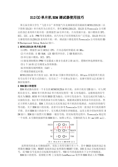
2 BDM接口和使用BDM调试器内部有一个8位的MC9HC08JB16单片机,该单片机有USB接口,可与PC 机信息交互。
HC08单片机和S12单片机间仅使用一根 I/O线通信,这根相连的信号线名为BKGD。
HC08单片机将BKGD置为输出,以串行发送命令,发送完成后转为输入,以接收信息。
S12单片机收到命令后转为输出,根据调试器发来的命令回送信息,然后立即转入接收态。
BDM工具以此方式实现S12单片机的在线调试、内部闪存的烧写等功能。
关于BDM接口的实现,读者可以参考Freescale任何一款S12单片机的器件手册,其对BDM接口的命令字、交互模式等都有详细描述。
ACM1281 用户手册说明书

带SAM卡槽的非接触式读写器模块用户手册 V1.03目录1.0.简介 (3)2.0.引脚分配 (4)2.1.配置LED操作状态 (4)2.1.1.LED操作 (4)2.2.ACM1281通过USB接口连接其他设备(仅适用于ACM1281U-C) (5)2.3.ACM1281通过串口连接其他设备(仅适用于ACM1281S-C) (7)3.0.与导电材料的最小距离 (9)图目录图1:ACM1281的主板 (3)图2:ACM1281 LED指示灯配置 (4)图3: ACM1281U-C(通过USB接口) (5)图4: 焊接在PCB上的插座J2尺寸 (6)图5: USB线材端的公插尺寸(连接J2) (6)图6:ACM1281S-C(通过串口) (7)图7: 焊接在PCB上的插座J5尺寸 (8)图8: RS-232线材端的公插尺寸(连接J5) (8)表目录表1: 与导电材料的建议最小距离 (9)1.0. 简介ACM1281是一款基于13.56 MHz技术的带SAM卡槽的非接触式读写器模块。
它支持ISO 14443第1-4部分的A类和B类卡以及MIFARE® Classic系列卡,读取智能卡的距离可达50 mm(视标签的类型而定)。
ACM1281采用模块形式,提供两种不同的接口版本,分别是配有USB接口的ACM1281U-C和配有串行接口的ACM1281S-C,专为快速轻松地集成到嵌入式系统而设计。
另外它还内置一个符合ISO7816标准的SAM(安全存取模块)卡槽,能够与SAM卡配合使用,为非接触式交易提供高级别的安全性。
ACM1281采用板线一体设计,可选配USB和串行连接线,还支持USB固件升级和扩展的APDU等功能。
另外ACM1281最高能以848 Kbps的速度与非接触式卡片进行通信,非常适合要求较高的应用,例如自动售货机的支付系统、自助服务终端、游戏机、以及其他采用不同串行端口的集成系统。
三极管参数表
常用三极管参数表下表是常用三极管的一些参数以及替换型号器件型号电压电流代换型号LM9011 SS9011LM901240V SS901240V A129840V CS9013 JE9013LM901340V SS901340V C326550V CS9014 JE9014LM9014 SS901450V C1623LM9015 SS9015TEC9015 50V TEC9015A 50V TEC9015B 50V TEC9015C 50V BC557 2N3906 BC557 2N3906 BC557 2N3906 BC557 2N39063DG9011 50V9011 50V9012 40V9012(HH)9012LT13DG90139013 40V9013(HH)9013LT13DG90149014 50V9014LT19015 50V2N4124 CS9011 JE90113DG9016 30V JE90169016 30V SS9016TEC9016 40V BF240 BF254 BF5948050 40V SS80508050LT1 40V KA3265ED8050 50V BC337SDT85501 60V 10A 3DK104CSDT85502 80V 10A 3DK104CSDT85503 100V 10A 3DK104DSDT85504 140V 10A 3DK104ESDT85505 170V 10A 3DK104FSDT85506 60V 10A 3DK104CSDT85507 80V 10A 3DK104CSDT85508 100V 10A 3DK104DSDT85509 140V 10A 3DK104EED8550 50V BC3378550 40V LM8550 SS85508550LT1 40V KA32652SA1015 50V BC177 BC204 BC212BC213BC251 BC257 BC307 BC512 BC557 CG1015 CG673 2SC1815 60V BC174 BC182 BC184 BC190 BC384 BC414 BC546 DG458 DG18152SC1815L 60V BC550 2SC2240 2S26742SC2675 2SC33782SC1815LT1 60V 9014LT12SC945 60V BC107 BC171 BC174 BC182BC183 BC190 BC207 BC237 BC382 BC546 BC547 BC582 DG945 2N2220 2N2221 2N2222 3DG120B 3DG4312 MMBT3904 40V BCW72 3DG120CMMBT3906 40V BCW70 3DG120CMMBT2222 木知BCX19 3DG120CMMBT2222A 75V 3DK10CMMBT5401 160V 3CA3FMMBTA92 300V 3CG180HBC807 50V BC338 BC537 BC635 3DK14BBC807R 50V BCX17 BCX17R BCW68BCW68RBC807-W 50V BCX17 BCW68 2SB1219ABC817 50V BCX19 BCW65 BCX66BC817R 50V BCX19 BCX19R BCW65BCW65R BCX66 BCW66RBC817-W 50V BCX19 BCW65 BCW66 2SD1820 2SD1949BC846 80V BCV71 BCV72BC846R 80V BCV71 BCV71R BCV72 BCV72RBC846-W 80V BCV71 BCV72 BCV72RBC847 50V BCW71 BCW72 BCW81BC847R 50V BCW71 BCW71R BCW72BCW72R BCW81 BCW81RBC847-W 50V BCW71 BCW72 BCW812SC4101 2SC4102BC848 30V BCW31 BCW32 BCW33 BCW71BCW72 BCW81BC848R 30V BCW31 BCW31R BCW32BCW32R BCW33 BCW33R BCW71 BCW71R BCW72 BCW72R BCW81 BCW81RBC848-W 30V BCW31 BCW32 BCW33 BCW71 BCW72 BCW81 2SC4101 2SC4102 2SC4117BC856 50V BCW89BC856R 80V BCW89 BCW89RBC856-W 80V BCW89 2SA1507 2SA1527BC857 50V BCW69 BCW70 BCW89BC857R 50V BCW69 BCW69R BCW70BCW70R BCW89 BCW89RBC857-W 50V BCW69 BCW70 BCW892SA1507 2SA1527BCW89BC858R 30V BCW29 BCW29R BCW30BC858 30V BCW29 BCW30 BCW69 BCW70 BCW30R BCW69 BCW69R BCW70 BCW70R BCW89BCW89RBC858-W 30V BCW29 BCW30 BCW69 BCW70 BCW89 2SA1507 2SA15272SA733 60V BC177 BC204 BC212 BC213 BC251 BC257 BC307 BC513 BC557 3CG120C 3CG4312MMUN211150V UN2111MUN2111 50V MMUN2111UN2111 50V FN1A4M DTA114EK RN24022SA1344MMUN2112 50V UN2112MUN2112 50V MMUN2112UN2112 50V FN1F4M DTA124EK RN24032SA1342MMUN2113 50V UN2113MUN2113 50V MMUN2113UN2113 50V FN1L4M DTA144EK RN24042SA1341MMUN221150V UN2211MUN2211 50V MMUN2211UN2211 50V DTC114EK FA1A4M RN14022SC3398MMUN2212 50V UN2212MUN2212 50V MMUN2212UN2212 50V DTC124EK FA1F4M RN14032SC3396MMUN2213 50V UN2213MUN2213 50V MMUN2213UN2213 50V DTC144EK FA1L4M RN14042SC33952SC3356 20V 2SC3513 2SC3606 2SC38292SC3838K 30V BF517 BF799 2SC30152SC3016彩显中易损大功率三极管主要参数表型号功率(W) 反压(V) 电流(A) 功能BU208A 50 1500 5电源开关管BU508A 75 1500 8电源开关管BU2508AF 45 1500 8行管* BU2508DF 125 1500 8行管* BU2508D 1251500 8 行管BU2520AF 45 1500 10行管BU2520AX 45 1500 10行管* BU2520DF 125 1500 10行管BU2522AF 45 1500 10行管* BU2522DF 80 1500 10行管* BU2525DF 45 800 12行管BUH51560 1500 8 行管C1520 10 250 视放C1566 250 视放C1573 250 视放C1875 50 1500 电源开关管C3153 100 900 6电源开关管C3026 50 1700 5 行管C3457 50 1100 3电源开关管C3459 90 1100 电源开关管C3460 100 1100 6电源开关管C3461 140 1100 8 行管*C3683 50 1500 5 行管C3686 50 1400 8 行管C3687 150 1500 8 行管C3481 120 1500 5电源开关管迦9 oom o g o s coQ *迦08。
飞思卡尔128单片机重点模块讲解

当我们将 A 口作输入口使用时需要设置 A 口内置上拉电阻时首先写 PUCR_PUPAE=1; 当我们将 B 口作输入口使用时需要设置 B 口内置上拉电阻时首先写 PUCR_PUPBE=1; 当我们将 E 口作输入口使用时需要设置 E 口内置上拉电阻时首先写 PUCR_PUPEE=1;
基于飞思卡尔 MC9S12XS128MCU 的模块讲解及测试
if(LED==0x20) //判断高电平信号是否移到第 6 位 LED=0x01; //重新赋初始值
} } � 源代码: (基于 STC52RC 单片机) #include "reg52.h" #define LED P1 // 选择 P1 口作为通用输出口 #define uchar unsigned char #define uint unsigned int void delay(uint a) { uint i,j; for(i=0;i<a;i++) for(j=0;j<a;j++) ; } void main() { LED=0x01; while(1) { LED=LED<<1; // 让高电平信号进行左移一位 // 点亮第一只发光二极管
基于飞思卡尔 MC9S12XS128MCU 的模块讲解及测试
安徽工业大学 自动化系 刘昌元 delay(500); if(LED==0x80) LED=0x01; } } 综合以上的两段代码看在 52 单片机和 128 单片机上编程思路基本上没大的区别,唯一的区 别就是 128 单片机有数据方向寄存器来管理 I/O 口。 � 将部分端口做输入口使用,另外一部分端口做输出口使用时:例如我们将 PORTB 的端 口 B7 用来做输入口,B0-B5 口做输出指示,测试代码如下:
adum1281串口使用案例

adum1281串口使用案例English Answer:ADuM1281 Serial Port Use Case:The ADuM1281 is an isolated RS-232 transceiver that provides up to 2.5 kV of isolation between the serial port and the isolated side. This makes it ideal for use in applications where there is a need to isolate the serial port from the rest of the system, such as in medical devices, industrial controls, and data acquisition systems.The ADuM1281 is a low-power device that operates from a single 3.3 V or 5 V supply. It has a data rate of up to 1 Mbps and is compatible with both RS-232 and RS-485 standards.The ADuM1281 is available in a small, 8-pin SOIC package. It is easy to use and requires no external components.Here is a typical use case for the ADuM1281:In a medical device, the ADuM1281 can be used to isolate the serial port from the patient. This helps to protect the patient from electrical shocks and other hazards.In an industrial control system, the ADuM1281 can be used to isolate the serial port from the noisy environment. This helps to ensure that the serial port data is not corrupted.In a data acquisition system, the ADuM1281 can be used to isolate the serial port from the sensitive data acquisition circuitry. This helps to ensure that the data acquisition system is not affected by noise or other interference.The ADuM1281 is a versatile device that can be used in a variety of applications. It is a low-power, easy-to-use device that provides high levels of isolation.Chinese Answer:ADuM1281串口使用案例:ADuM1281是一款隔离式RS-232收发器,可在串口与隔离侧之间提供高达2.5 kV的隔离电压。
Matrox Meteor-II Camera Link相机接口应用指南说明书

JAI CV-M4CL March 26, 2002Basics about thecameraCamera Descriptions§Effective resolution: 1280 × 1024 × 10-bit @ 24 fps (Full resolution). §Camera Link BASE interface (single channel).§Progressive scan.§Internal or external sync.§Internal or external exposure control.§40.49 MHz pixel clock rate.Mode of operations as per Matrox Imaging (in parentheses as per camera manufacturer)Interface Mode §Continuous§Asynchronous resetBasics about theinterface modesCamera Interface BriefsMode 1: Continuous§1280 × 1024 × 10-bit @ 24 fps (Full resolution).§Camera Link BASE interface (single channel).§Progressive scan.§Matrox Meteor-II/Camera Link receiving LEN, FEN, Pclk and video data fromcamera.§ DCF used:CVM4CLC.DCFMode 2: Asynchronous reset (Pulse width control trigger)§1280 × 1024 × 10-bit.§Camera Link BASE interface (single channel).§Progressive scan.§Matrox Meteor-II/Camera Link receiving external trigger signal.§Matrox Meteor-II/Camera Link sending EXPOSURE1 (CC1) signal to camerato initiate and control exposure time.§Matrox Meteor-II/Camera Link receiving LEN, FEN, Pclk and video data fromcamera.§ DCF used:CVM4CLA.DCFJAI CV-M4CL March 26, 2002 Specifics about theCamera Interface Detailsinterface modesMode 1: Continuous§Frame Rate: Matrox Meteor-II/Camera Link receives the continuousvideo from the camera at 24 frames per second (Full resolution).§Exposure time: Exposure time is determined by the shutter setting.Refer to the camera manual for more information.§Camera switch settings: Refer to the camera manual for additionalinformation. Internal and external switches should be set as follows:External Switches Internal Switches (SW50)Shutter 1 OFF 1 OFFShutter 2 OFF 2 ONShutter 3 OFF 3 OFFShutter 4 OFF 4 OFFExt. Trigger 5 OFFExt. Trigger 6 OFFScan 7 OFFScan 8 OFFSmear-less 9 OFFControl 10 OFFMode 2: Asynchronous reset (Pulse width control trigger)§Frame Rate: The frame rate is determined by the frequency of theexternal trigger signal and the exposure time period.§Exposure time: The width (falling edge to rising edge) of theEXPOSURE1 (CC1) signal is the exposure time. The exposure time canbe modified in the DCF using Matrox Intellicam, with the MILMdigControl() function. Consult the respective manual for moreinformation.§Camera switch settings: Refer to the camera manual for additionalinformation. Internal and external switches should be set as follows:External Switches Internal Switches (SW50)Shutter 1 OFF 1 OFFShutter 2 OFF 2 ONShutter 3 OFF 3 OFFShutter 4 OFF 4 OFFExt. Trigger 5 ONExt. Trigger 6 OFFScan 7 OFFScan 8 OFFSmear-less 9 OFFControl 10 OFFMatrox Meteor-II/Camera Link Camera Interface Application NoteJAI CV-M4CL March 26, 2002 Cabling details for theCabling Requirementsinterface modesMode 1: ContinuousCable and Connection: Standard Camera Link cable.Mode 2: Asynchronous reset (Pulse width control)Cable and Connection: Standard Camera Link.External trigger: External trigger should be connected to the OPTOTRIG input of the DB9 connector (pins 7 and 2) on the Expanded I/Oadapter bracket.EXPANDED I/O BRACKET(DB9 connector) External Trigger SourceOPTOTRIG + 07 ←SIGNAL --OPTOTRIG - 02 ←GROUND --The DCF(s) mentioned in this application note can be found on our FTP site (/pub/imaging/).The information furnished by Matrox Electronics System, Ltd. is believed to be accurate and reliable. Please verify all interface connections with camera documentation or manual. Contact your local sales representative or Matrox Sales office or Matrox Imaging Applications at 514-822-6061 for assistance.Matrox Electronic Systems Ltd.1055 St. Regis Blvd.Dorval, Quebec H9P 2T4CanadaTel: (514) 685-2630Fax: (514) 822-6273。
VCS后缀选项说明
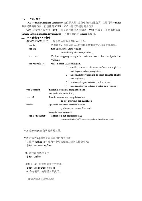
一、VCS简介VCS(Verilog Compiled Simulator)定位于大型、复杂电路的快速仿真,主要用于Verilog 源代码的编译仿真,但也能对VHDL、C/C++源代码进行混合仿真。
VCS支持命令行方式(CLI),为了进行图形界面调试,VCS包含了一个图形仿真器VirSim(Virtual Simulator Environment),下面主要讲述VirSim的使用。
二、VCS的简单CLI命令在VCS的CLI方式下,输入的所有命令都以vcs开头。
vcs -h 帮助命令,列表显示vcs后可跟的所有命令选项及简单解释;vcs -RI Run Interactive. Starts VirSimimmediately after compilation ;vcs -line Enables stepping through the code and source line breakpoints inVirSim ;vcs +cli+1|2|3|4 +cli Enable CLI debugging,1enables you to see the values of nets and registersand deposit values to registers;2also enables breakpoints on value changes of netsand registers ;3also enables you to force a value on nets ;4also enables you to force a value on a register ;vcs -Mupdate Enable incremental compilation andoverwrite the make file ;vcs –M Enable incremental compilation,butdo not overwrite the makefile ;vcs –f Specifies a file that contains a list ofpathnames to source files andcompile-time options ;vcs -i <filename> Specifies a file containing CLIcommands that VCS executes when simulation starts ;VCS是Synopsys公司的仿真工具.VCS对verilog模型进行仿真包括两个步骤:1. 编译verilog文件成为一个可执行的二进制文件命令为:$> vcs source_files2. 运行该可执行文件$> ./simv类似于NC, 也有单命令行的方式:$> vcs source_files -R-R 命令表示, 编译后立即执行.下面讲述常用的命令选项:-cm line|cond|fsm|tgl|obc|path 设定coverage的方式+define+macro=value+ 预编译宏定义-f filename RTL文件列表+incdir+directory+ 添加include 文件夹-I 进入交互界面-l logfile文件名-P pli.tab 定义PLI的列表(T ab)文件+v2k 使用推荐的标准-y 定义verilog的库-notice 显示详尽的诊断信息-o 指定输出的可执行文件的名字,缺省是sim.vzz 51lifeSummary of vcs compile options:--------------------------------ASFLAGS "opts" pass 'opts' to the assembler-B generate long call instructions in native assembly code(HP only)-CC "opts" pass 'opts' to C compiler-CFLAGS "opts" pass 'opts' to C compiler-LDFLAGS "opts" pass 'opts' to C compiler on load line only-I enable interactive/postprocessing debugging capabilities-ID get host identification information-M enable incremental compilation (see manual)-Mupdate enable incremental compilation and keep the Makefile up-to-date-Marchive[=N] create intermediate libs to reduce link line length; N objs per lib-P plitab compiles user-defined pli definition table 'plitab'-PP enable optimizer postprocessing capabilities for vcd+-R after compilation, run simulation executable-RI after compilation, run simulation under xvcs (Implies -I)-RIG run simulation under xvcs without compiling (executablehas to exist)-RPP run xvcs in postprocessing mode (requires file created by vcdpluson)-V[t] verbose mode; with 't', include time information-as foo use foo as the assembler-cc foo use foo as the C compiler-cpp foo use foo as the C++ compiler-e <new_name> specify the name of your main() routine.(see manual section 7-11 for more details).-f file reads 'file' for other options-gen_c generate C code (for HP and Sun, default is -gen_obj) -gen_asm generate native assembly code (HP and Sun only)-gen_obj generate native object code (HP and Sun only)-ld foo use foo as the linker. (refer vcs manual for compatibility with -cpp option)-line enable single-stepping/breakpoints for source level debugging-lmc-swift include lmc swift interface-lmc-hm include lmc hardware modeler interface-vera add VERA 4.5+ libraries-vera_dbind add VERA 4.5+ libraries for dynamic binding-location display full pathname to vcs installation for this platform -vhdlobj <name> generate a vhdl obj for simulating in a vhdl design -mixedhdl include MixedHDL-1.0 interface-mhdl include MixedHDL-2.0 interface and library-q quiet mode-platform display name of vcs installation subdirectory for this platform-syslib 'libs' specify system libraries (placed last on the link line) eg -lm-o exec name the executable simulation model 'exec' (default is 'simv')-u treat all non text string characters as uppercase-v file search for unresolved module references in 'file'-y libdir search for unresolved module references in directory'libdir'+acc enable pli applications to use acc routines (see manual) +ad include anlog simulation interface and library+adfmi="files" ADFMI support for vcs-ace+cliedit enable command line edit/recall (see doc/readline.ps)+cli enable command line interactive debugging (see manual) +cmod Enabling cmodule feature+cmodext+cmodext Changing cmodule extension to cmodext+cmodincdir+cmoddir Cmodule Include directory+cmoddefine+macro define cmodule source 'macro' in the form ofXX=YY+define+macro define hdl source 'macro' to have value "macro"+plusarg_save hardwire the plusargs, which follow this flag, intosimv+plusarg_ignore turn off +plusarg_save+prof tells vcs to profile the the design and generate vcs.proffile+race tells vcs to generate a report of all race conditions during simulationand write this report in the race.out file+rad+1 enable level 1 radiant optimizations (See Release Notes) +rad+2 enable level 2 radiant optimizations (See Release Notes) +libext+lext use extension 'lext' when searching library directorys+librescan search from beginning of library list for all undefinedmods+incdir+idir for `include files, search directory 'idir'+nospecify suppress path delays and timing checks+notimingchecks suppress timing checks+optconfigfile+foo use 'foo' as the optimization config file (See ReleaseNotes)+vcsd enable the VCS Direct sim kernel interface-cmhelp enable CoverMeter help. CoverMeter should beinstalledand environment variable CM_HOME should be set.-cm enable VCS to first run cmSource to instrument theVerilog source files on the command line, and then tocompile the instrumented source files-cm_all enable VCS to link CoverMeter into the VCS executable in a way that enables line, condition, and FSM coverageand establishes the direct link. Enabling all types of coverage and thedirect link is the default condition when you include the -cm option soyou can omit this option-cm_lineonly enable VCS to link CoverMeter into the VCSexecutable in a way that only enables line coverage when italso establishes the direct link. Use this option for faster simulation and when you only need line coverageCompile-Time Options********************-f <filename>Specifies a file that contains a list of pathnames to source filesand compile-time options.-F <filename>Same as the -f option but allows you to specify a path to the fileand the source files listed in the file do not have to be absolute pathnames.-hDisplays a succinct description of the most commonly used compile-time and runtime options.-l <filename>(lower case L) Specifies a log file where VCS records compilation messages and runtime messages if you include the -R, -RI, or-RIG options.-lineEnables stepping through the code and source line breakpoints in VirSim. -MEnables incremental compilation, but do not overwrite the makefile.-MupdateEnable incremental compilation and overwrite the make file.-noticeEnables verbose diagnostic messages.-o <name>Specifies the name of the executable file that is the product of compilation. The default name is simv (simv.exe on Windows).-ova_covEnables functional coverage.-P <pli.tab>Specifies a PLI table file.-RRun the executable file immediately after VCS links together the executable file. You can add any runtime option to the vcs command line.-sStop simulation just as it begins. Use this option with the -R and+cli options.-timescale=<time_unit>/<time_precision>If only some source files contain the `timescale compiler directiveand the ones that don't appear first on the vcs command line, usethis option to specify the time scale for these source files.-VEnables the verbose mode.-v <filename>Specifies a Verilog library file to search for module definitions.Specifies the standard VERA PLI table file and object library.-y <directory_pathname>Specifies a Verilog library directory to search for module definitions.+2stateEnables 2 state simulation.+cli+[<module_name>=]1|2|3|4Enable CLI debugging.1 enables you to see the values of nets and registers and deposit values to registers.2 also enables breakpoints on value changes of nets and registers.3 also enables you to force a value on nets.4 also enables you to force a value on a register.You can specify a module to enable CLI debugging only for instances of the module.+define+<macro_name>=<value>Defines a text macro. Test for this definition in your Verilogsource code using the `ifdef compiler directive.+incdir+<directory>Specifies the directories that contain the files you specified withthe `include compiler directive. You can specify more that one directory, separating each path name with the + character.+libext+<extension>Specifies that VCS only search the source files in a Verilog library directory with the specified extension. You can specify more than one extension, separating each extension with the + character.For example, +libext++.v specifies searches library files with no extension and library files with the .v extension.Enter this option when you enter the -y option.+maxdelaysUse maximum value when min:typ:max values are encountered in delay specifications SDF files.+mindelaysUse minimum value when min:typ:max values are encountered in delay specifications and SDF files.+notimingcheckSuppresses timing checks in specify blocks.+plusarg_ignoreAlso enter this option in the file that you specify with the -f option so that VCS does not pass to the simv executable or to VirSim the options that follow in the file. Use this option with the+plusarg_save option to specify that other options shouldnot be passed.Specifies that VCS generate a report, during simulation, of all therace conditions in the design and write this report in the race.outfile.+race=allAnalyzes the source code during compilation to look for codingstyles that cause race conditions.+rad or +rad+2Performs aggressive optimizations on your design.+rad+1 or +radlite or +radlightPerforms less aggressive optimizations on your design.+v2kEnables the use of new Verilog constricts in the 1364-2001 standard.Runtime Options***************-i <filename>Specifies a file containing CLI commands that VCS executes when simulation starts.-l <filename>Specifies writing all messages from simulation to the specifiedfile as well as displaying these messages in the standard output.This option begins with the letter "l" (lowercase "L") for log file.-ova_covEnables functional coverage reporting.-sStops simulation just as it beings, and enters interactive mode.Use with the +cli+<number> option.-VVerbose mode. Print VCS version and extended summary information. Prints VCS compile and run-time version numbers, and copyright information, at start of simulation.-vcd <filename>Sets the output VCD file name to the specified file.The default filename is verilog.dump.A $dumpfile system task in the Verilog source code will overridethis option.+maxdelaysSpecies using the compiled SDF file for maximum delays generatedby the +allmtm compile-time option.Also specifies using maximum delays for SWIFT VMC or SmartModels or Synopsys hardware models if you also enter the+override_model_delays runtime option.+mindelaysSpecifies using the compiled SDF file for minimum delays generatedby the +allmtm compile-time option.Also specifies using minimum delays for SWIFT VMC or SmartModels or Synopsys hardware models if you also enter the+override_model_delays runtime option.+notimingcheckSuppress timing checks.+override_model_delaysEnables you to use the +mindelays, +typdelays, or +maxdelays runtime options to specify timing for SWIFT SmartModels or Synopsys hardware models.+sdfverboseEnables the display of more than ten warning and ten error messages about SDF back annotation.+vcs+dumpoff+<t>+<ht>Turn off value change dumping ($dumpvars system task) at time <t>.<ht> is the high 32 bits of a time value greater than 32 bits.+vcs+dumpon+<t>+<ht>Suppress $dumpvars system task until time <t>.<ht> is the high 32 bits of a time value greater than 32 bits.+vcs+dumpvarsoffSuppress $dumpvars system tasks.+vcs+finish+<t>+<ht>Finish simulation at time <t>.<ht> is the high 32 bits of a time value greater than 32 bits.Options for Using VirSim Interactively or in Post-Processing************************************************************+cfgfile+<filename>Specifies using a configuration file that you recorded in aprevious session with VirSim.+vslogfile[+<filename>]Enables logging of VirSim commands in a VirSim log file. If you do not specify a filename, the log is automatically saved to the working directory as VirSim.log.Options For Using VirSim************************the following are options for using VirSim. You enter them on thevcs command line and also specify the source files.Options for Using VirSim interactively with VCS+++++++++++++++++++++++++++++++++++++++++++++++-RIRun Interactive. Starts VirSim immediately after compilation.-RIGRun Interactive Debug. Start VirSim using an existing executablefile (such as the simv or simv.exe file). VCS does no compilation.+sim+<simv_name>Use with the -RIG option. You need this option to specify the nameof the simv executable file that isn't named simv but has a different name that you specified with the -o compile-time option.+vslogfilesim[+<filename>]Enables the logging of VCS communication messages in the VirSim log file. If you use both +vslogfile and +vslogfilesim, VirSim commands and VCS messages are saved to the same file.If you do not specify a filename, the log is automatically savedto the working directory as VirSim.log.+vpdfile+<filename>At runtime, defines an alternative name of the VCD+ file that VCS writes instead of the default name vcdplus.vpd.Options for Using VirSim in Post-Processing+++++++++++++++++++++++++++++++++++++++++++-RPPRun Post-Processing mode. Starts VirSim for post-processing a VCD+ file.+vcdfile+<filename>Specifies the VCD file you want to use for post-processing.+vpdfile+<filename>[+start+<start_time>+end+<end_time>]In post-processing, specifies the VCD+ file you wish to view in VirSim. The optional +start+<start_time> and +end+<end_time> arguments specify you only want VirSim to display the resultsfrom between these simulation times.Options for Specifying How VCS Writes the VCD+ File+++++++++++++++++++++++++++++++++++++++++++++++++++-PPEnables system tasks and options for VCD+ files and optimizationsfor faster post-processing.-IEnables system tasks and options for VCD+ files.+vpdbufsize+<MB>VCS uses an internal buffer to store value changes before it writes them to the VCD+ file on disk. VCS makes this buffer size either 5 MB or large enough to record 15 value changes for all nets and registers in your design, which ever is larger.You can use this option to override the buffer size that VCS calculates for the buffer size. You specify a buffer size in megabytes.+vpddriversTells VCS to record the values of all the drivers of all the nets.+vpdfilesize+<MB>Specifies the maximum size of the VCD+ file. When VCS reaches this limit, VCS overwrites the oldest simulation history data in the file with the newest.+vpdignoreTells VCS to ignore $vcdplus system tasks so VCS does not write a VCD+ file.+vpdportsTells VCS to record, in the VCD+ file, the port direction of signals that are ports.+vpdnocompressDisables the automatic compressing of the data in VCD+ files.+vpdupdateIf VCS is writing a VCD+ file during simulation, this option enables you to have VCS halt writing to the VCD+ file while the simulation is running and so that you can view the recorded results in VirSim. This option enables you to use the update feature in VirSim.+vpdnostrengthsDisables recording strength information in the VCD+ file.Options For CAlling The vcd2vpd and vpd2vcd Utilities*****************************************************-vcd2vpd <vcd_filename> <vcdplus_filename>Tells VCS to find and run the vcd2vpd utility that converts a VCD file to a VCD+ file. VCS inputs to the utility the specified VCDfile and the utility outputs the specified VCD+ file.-vpd2vcd <vcdplus_filename> <vcd_filename>Tells VCS to find and run the vpd2vcd utility that converts a VCD+ file to a VCD file. VCS inputs to the utility the specified VCD+file and the utility outputs the specified VCD file.The Virsim debugger and the vpd2vcd and vcd2vpd translator utilities are best invoked via the vcs command line.Summary of vcs options for the $vcdpluson tasks:-------------------------------------------------I enable interactive/postprocessing debugging capabilities-PP enable optimizer postprocessing capabilities for vcd++vcsd enable the VCS DKI (Direct Kernel Interface); +vpdports,+vpddrivers, output and interactivesimulation currently are not available in +vcsd mode.Summary of vcs options for the Virsim GUI:-------------------------------------------RI after compilation, run simulation under Virsim (implies -I)-RIG run simulation under Virsim without compiling (executable has to exist)-RPP run Virsim in postprocessing mode (requires file created by $vcdpluson)Additional Virsim Verilog and $vcdpluson flags:-----------------------------------------------VirSim 4.3.R11 Virtual Simulator EnvironmentCopyright (C) 1993-2003 by Synopsys, Inc.Licensed Software. All Rights Reserved.Usage: vcs [-RI|-RIG|-RPP] [[+vpdfile+<vpdname>]...] [[+vcdfile+<vcdname>]...] [[+cfgfile+ <cfgname>]...][sim-opts] [vpd-opts-to-pli] [other-opts] files+vpdfile+<vpdname> Multiple VPD files can be opened using several+vpdfile+ commands+vcdfile+<vcdname> Multiple VCD files can be opened using several+vcdfile+ commands+cfgfile+<cfgname> Multiple (incremental) configuration files can be loadedsim-opts:+sim+<simulator-path> Sets simulator path name+simtype+<simulator> Sets simulator type exactly as listed in SimulatorInvocation Dialog+simargs+<parameters> Sets additional simulator arguments. Double quotesaround multiple arguments.+simargs+"+vpdfile+<vpdname>" Sets name of VPD file to be created by VCD+ PLI vpd-opts-to-pli: Options for VCD+ generation by an interactivesimulation run started by virsim+vpdports Stores port type information for hierarchy+vpddrivers Stores data for changes on drivers of resolved nets+vpdbufsize+<#MB> Changes the default size of the internal VCD+ buffer+vpdfilesize+<#MB> Sets file size when storing data in wraparound mode+vpdupdate Enables VPD file locking+vpdignore Tells simulator to ignore all calls to generate VPD+vslogfile Enables message logging. Does not log simulation communication messages+vslogfile+<filename> Enables message logging. Logs messages in filename+vslogfilesim Enables logging of simulation communication messagesother-opts: Sets regular options to compile verilog code+v2k Enables supported verilog 2000 additionsfiles: Verilog source code file(s) listSummary of vcd2vpd options:---------------------------Usage: vcs -vcd2vpd <options> <evcd_options> <vcd_file> <vpd_file><options>-b# Buffer size in KB used to store Value Change Data beforewriting it to disk.-f# Maximum output file size in KB. Wrap around occurs ifthe specified file size is reached.-h Translate hierarchy information only.-m Give tranlsation metrics during translation.-q Suppress printing of copyright and other informational messages.+deltacycle Add delta cycle information to each signal value change.+glitchon Add glitch event detection data.+nocompress Turn data compression off.+nocurrentvalue Do not include object's current value at the beginning of each VCB. <evcd_options>+dut+<dut_prefix> Modifies the string identifier for the Device-Under-Testhalf of the split signal. Default is "DUT".+tf+<tf_prefix> Modifies the string identifier for the Test-Fixturehalf of the split signal. Default is "TF".+indexlast Appends the bit index of a vector bit as the lastelement of the name.Summary of vpd2vcd options:---------------------------Usage: vcs -vpd2vcd <vpd_file> [<vcd_file>]Summary of vpd2vcd command line options-h Translate hierarchy information only.-q Suppress printing of copyright and other informational messages.-s Allow sign extension for vectors. Reduces size of <vcd_file>.-x Expand vector variables to full length when displaying$dumpoff value blocks.+zerodelayglitchfilter Zero delay glitch filtering for multiple value changes within the same time unit.+morevhdl Translates the vhdl types that are not directly mappable toverilog types in addition to the ones that are mappable.+start+<value> Translate value changes starting after start time <value>+end+<value> Translate value changes ending before end time <value>(Note) If both start and end values are input, value changesoccuring between start and end time are translated.。
VCS介绍

VCS的方案均采用了高性能的VERITAS存储软件作为存储管理和高性能数据访问软件。
鉴于提高数据库性能的考虑,我们配置了VERITAS Quick I/O 的Oracle数据库加速产品,使得数据库的处理能力大大提高。
作为系统安全的保障,我们配置了VERITAS群集管理(VERITAS Cluster Server,VCS)作为系统的高可用软件。
VCS能够对应用、系统、数据库系统、网络、备份等均提供高效快速的故障保护。
我们在各节点均采用了VERITAS V olume Manager 和VERITAS File System作为虚拟磁盘管理和高性能文件系统。
这两种产品各具优点,两者有机结合后,利用双方特有的对磁盘和数据的管理能力,能给企业的系统提供尽可能高的性能、可用性及可管理性。
---- VCS是一款高可用性多机应用软件,可以通过应用在各服务器之间的智能化灵活切换,使多台服务器协同工作,支持Unix和Windows NT环境。
作为多机的集群软件,VCS对应用的切换具有速度快、方式灵活的特点。
在SAN环境下,VCS可以支持最多32台服务器协同工作,在各种群集管理软件中优势突出,是目前扩展性最好高可用软件。
VCS还提供Windows NT控制工具和界面。
管理员可以做到无人现场值守即可监控群集的状态。
---- VERITAS Volume Manager为企业的应用提供了功能强大的磁盘和存储设备在线管理。
VERITAS V olume Manager提供虚拟设备机制(即逻辑卷),向用户应用和文件系统提供完全透明的设备在线管理,应用程序和文件系统无须直接管理物理设备,数据的安全性、完整性、I/O性能的调整、设备在线扩展由V olume Manager管理机制实现。
另外,服务器进行在线管理,不必因备份和维护而进行脱机。
VERITAS V olume Manager提供了磁盘的使用分析、RAID 配置和系统在线的情况下对磁盘进行动态配置。
长波长VCSEL能耗指标

长波长VCSEL能耗指标
长波长(LongWavelength,LW)VCSEL(可调谐腔谐振半导体激光器)是一种激光器,它的光谱波长通常在1.3毫米到2毫米之间。
这种激光器通常用于通信、激光打印、激光扫描和其他应用。
虽然长波长VCSEL的能耗指标可能会因应用而异,但通常情况下,其能耗指标包括功率、功率效率和增益带宽产品。
•功率:指激光器的输出功率,单位是瓦特(W)。
•功率效率:指激光器的输出功率与电流的比值,单位是瓦特每安培(W/A)。
•增益带宽产品:指激光器在某个频带内输出有效功率的增益与带宽的乘积,单位是(增益)x(带宽)。
希望这些信息对你有帮助!
1/ 1。
im1281b工作原理
im1281b工作原理
IM1281B是一款智能控制芯片,通常用于电机驱动、照明控制等应用场合。
它采用了高性能32位ARM内核,并且具有多种接口和协议支持,如UART、I2C、SPI等。
其工作原理主要包括以下几个方面: 1. 电源管理:IM1281B内置多种电源管理电路,可以对外部电源进行监测和控制,保证芯片的稳定工作。
2. 外设控制:IM1281B可以通过多种接口控制外部设备,如电机、LED等。
用户可以通过编程实现对这些设备的控制,以达到特定的应用目的。
3. 数据处理:IM1281B内置的32位ARM内核具有强大的数据处理能力,能够高效地进行数据计算和处理。
用户可以通过编程实现对数据的采集、处理和传输等功能。
4. 通信协议支持:IM1281B支持多种通信协议,如UART、I2C、SPI等。
用户可以通过这些接口实现与其他设备的通信和数据交换。
总之,IM1281B是一款功能强大的智能控制芯片,其灵活的接口和协议支持,以及高性能的数据处理能力,使其具有广泛的应用前景。
- 1 -。
EMC、光纤交换机及服务器配置过程总结
EMC、光纤交换机及服务器配置过程总结-----------------------作者:-----------------------日期:更多资料请访问.(.....)EMC、光纤交换机及服务器配置过程总结目录版本记录1概述本文主要从实用的角度整个描述EMC的划分、光纤交换机的配置以及服务器的设置,最终实现SAN环境中服务器成功分配EMC空间。
首先我们在光纤交换机上定义一些通道即zone,允许服务器与EMC通讯;其次EMC能够识别到服务器并将EMC空间划分给服务器;最后服务器成功识别到EMC划分的空间。
本文按照配置顺序对于配置过程中的步骤一一描述:本文配置过程背景:p550DB、mttest、gfstest1、gfstest2四台服务器需要通过光纤交换机连接EMC,p550DB、mttest能且只能访问EMC分配的独立空间;gfstest1、gfstest2也能能且只能够访问EMC划分的独立空间。
2光纤交换机配置2.1 现有光纤交换机信息现有SAN网络中使用光纤交换机两台,具体信息如下:2.1.1sw012、端口物理连接如下:2.1.2Sw02交换机型号EMC Conectrix DS16B3,端口物理连接如下:2.1.3设备连接汇总表2.2 光纤交换机配置2.2.1术语配置Zone需要涉及到三个对象的配置Alias,Zone,Configuration:Alias可以把设备的WWN或Domain,Port声明为Alias,用于更好更直观的标示设备;同时当Zone中的某个成员更换时,如果定义了Alias,只要修改Alias的定义就可以调整Zone 中的成员,而不用修改Zone的配置。
Zone区域,Zone内的设备可以相互访问,但不能访问其他Zone的设备;Zone的成员可以有三种:“Domain,Port”;”WWN”;”Alias”;Configuration在交换机上的一套关于Zone的配置,或者说一系列Zone的集合。
宽带低误差矢量幅度(EVM)直接变频发射机
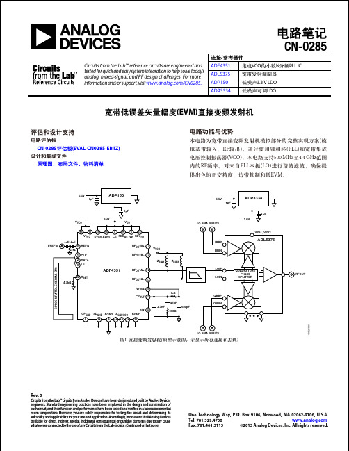
I/Q SMA INPUTS
VPS1, VPS2
DVDD AVDD
ADL5375
SPI-COMPATIBLE SERIAL BUS
ADF4351
22 RSET 4.7kΩ
RFOUTA+ 12 RFOUTA– 13 VTUNE 20 CPOUT 7 47nF 2.7nF SW 5 680pF 360Ω
R&S AMIQ GEN.
I+ I– Q+ Q– SPECTRUM ANALYZER [R&S FSQ 8]
常见变化
当单个滤波器无法完成所需的宽带操作时,可以使用 ADF4351的辅助输出,在两种类型的滤波器之间切换(见图 8)。使用一个 RF双刀四掷开关 (DP4T)选择滤波器 1或滤波 器2的差分输出。
10921-004
–70 800
Rev. 0 | Page 3 of 5
CN-0285
表3. 单载波W-CDMA复合EVM结果:ADF4351 RF输出端有滤波器和无滤波器两种情况对比 (根据3GPP规范测试模型4测量)
频率(MHz) 2140 1800 900 ADF4350复合EVM, 无LO滤波 3.27% 1.46% 10.01% ADF4350复合EVM,有LO滤波, 滤波器B 1.31% 1.13% 1.03% ADF4351复合EVM,有LO滤波, 滤波器B 1.02% 0.95% 0.96%
谐波成分 第二 第三 第二 第三 数值(dBc) −19 −13 −20 −10 描述 基波VCO输出 基波VCO输出 分频VCO输出 分频VCO输出
电路描述
图1所示电路使用完全集成的小数N分频PLL IC ADF4351和 宽带发射调制器 ADL5375 。 ADF4351 向发射正交调制器 ADL5375提供LO信号,后者将模拟I/Q信号上变频为RF信 号。两个器件共同提供宽带基带 I/Q至 RF发射解决方案。 ADF4351采用超低噪声3.3 V ADP150调节器供电,以实现最 佳LO相位噪声性能。ADL5375则采用5 V ADP3334 LDO供 电。ADP150 LDO的输出电压噪声仅为9 μV rms,有助于优 化VCO相位噪声并减少VCO推压的影响(等效于电源抑制)。 需要对 ADF4351 RF 输出进行滤波,以衰减谐波水平,使 ADL5375正交产生模块的误差最小。依据测量和仿真得 知,奇次谐波对正交误差的贡献大于偶次谐波;如果将奇 次谐波衰减至−30 dBc以下,则可以实现−40 dBc或更好的边 带抑制性能。ADF4351数据手册给出了其二次谐波(2H)和 三次谐波(3H)水平,如表1所示。 表2. ADF4351 RF输出滤波器元件值(DNI = 不插入)
- 1、下载文档前请自行甄别文档内容的完整性,平台不提供额外的编辑、内容补充、找答案等附加服务。
- 2、"仅部分预览"的文档,不可在线预览部分如存在完整性等问题,可反馈申请退款(可完整预览的文档不适用该条件!)。
- 3、如文档侵犯您的权益,请联系客服反馈,我们会尽快为您处理(人工客服工作时间:9:00-18:30)。
Dept / Issued by 93661 Lennart Petersson Issue 2 Established2011-05Page1(6)The English language version is the original and the reference in case of dispute. Den engelska språkversionen är originalversion och ska åberopas i händelse av tvist.Electrocoat paint (EC paint) 98121Elektrodopplack (ED-lack) 98121Orientation OrienteringThis issue differs from issue 1 in that the test methods for paint in liquid form have been replaced by international standards. Testing at different curing conditions has been clarified. The environmental requirements have been updated.New test methods and requirements have been included for:- corrosionresistance- stone chip resistance- edgecoverage- surfacetextureThe following requirements have been removed:- colour according to master panel- water spraying under high pressure at EC paint only. Denna utgåva skiljer sig från utgåva 1 genom att provningsmetoder för lack i flytande form har ersatts med internationella standarder. Provning vid olikahärdningsbetingelser har förtydligats. Miljökraven har uppdaterats.Nya provningsmetoder och krav har lagts till för:- korrosionsbeständighet- stenskottsresistens- kanttäckning- ytstrukturFöljande krav har tagits bort:- kulör enligt likare- högtrycksspolning med vatten på enbart ED-lack.Contents Innehåll1 Scope and field of application 1Omfattningochtillämpning 2 Requirements 2 Krav2.1 Paint in liquid form 2.1 Lack i flytande form2.2 Curing conditions 2.2 Härdningsbetingelser2.3 General requirements, cured paint film 2.3 Allmänna krav, härdad lackfilm2.4 Environmental requirements 2.4 Miljökrav2.5 Test panel 2.5 Provpanel2.6 Other requirements 2.6Övrigakrav1 Scope and field of application 1 Omfattning och tillämpningEC paint 98121 is an oven-curing, water-borne paint to be applied by cathodic electrocoating. The EC paint, which is intended to be applied as a first priming coat, shall penetrate easily into crevices and cavities. The paint shall protect against corrosion, adhere well to the substrate, and be a suitable base for subsequent paint systems. ED-lack 98121 är en ugnshärdande, vattenburen dopplack som appliceras genom katodisk elektro-doppning. ED-lacken, som är avsedd att användas som ett första grundlackskikt, ska ha en god inträng-ningsförmåga i spalter och hålrum. Lacken ska skydda mot korrosion, ha en god vidhäftning till underlaget, samt vara ett lämpligt underlag för efterföljande lacksystem.EC paints require a metal substrate. Narrow or closed structures should be provided with a suitable hole pattern so that the thickness of the EC paint is adequate on the interior surfaces. ED-lack kräver metalliskt underlag. Trånga eller slutna konstruktioner bör ha en lämplig håltagning för att ED-lacken ska uppnå tillräcklig skikttjocklek på invändiga ytor.2 Requirements 2 Krav2.1 Paint in liquid form 2.1 Lack i flytande formThese requirements are process-related and vary between different production facilities. Additional requirements can exist. Dessa krav är av processbetingad art och varierar mellan skilda produktionsanläggningar. Ytterligare krav kan förekomma.Table / Tabell 1Property Egenskap Test methodProvningsmetodEC paintED-lackpH valuepH-värdeISO 976Dry contentTorrhaltISO 3251 (180 °C, 30 min)Ash content Askhalt ISO 3451-1 method A (130 °C, 2 h + 800 °C, 1 h)Content of solventLösningsmedelshaltDIN 55682Conductivity Ledningsförmåga ASTM D4399The value shall be determinedand optimized for eachproduction facility respectively.If needed, an alternative testmethod can be used afteragreement between theproduction facility and the designresponsibleVärdet fastställs och optimerasför respektive produktions-anläggning.Vid behov kan alternativprovningsmetod användas efteröverenskommelse mellanproduktionsanläggning ochkonstruktionsansvarigFlash pointFlampunktApplies to replenishment materialsGäller efterfyllnadsmaterialISO 3679 ≥ 60 °C2.2 Curing conditions 2.2 HärdningsbetingelserTime and temperature for undercured, normal cured, and overcured EC paint shall be established by the testing department and the design-engineering department in joint consultation on the basis of the supplier’s curing window. Tid och temperatur för underhärdad, normalhärdad och överhärdad ED-lack fastställs i samråd mellan provande instans och konstruktionsavdelning med leverantörens härdningsfönster som underlag.All properties in this standard shall be verified with normal cured EC paint. Samtliga egenskaper i denna standard ska verifieras med normalhärdad ED-lack.The following properties shall also be verified with undercured EC paint:- adhesion- moisture resistance excl. stone chip resistance. The following properties shall also be verified with overcured EC paint:- adhesion- moistureresistance- stone chip resistance. Följande egenskaper ska dessutom verifieras med underhärdad ED-lack:- vidhäftning- fuktbeständighetexkl.stenskottsresistens.Följande egenskaper ska dessutom verifieras med överhärdad ED-lack:- vidhäftning- fuktbeständighet- stenskottsresistens.The other paint layers included in the complete paint system shall be normal cured in accordance with the specification applicable to the respective paint layer. De övriga lackskikten ingående i det hela lack-systemet ska vara normalhärdade enligt gällande specifikation för respektive lackskikt.2.3 General requirements, cured paintfilm2.3 Allmänna krav, härdad lackfilm Table / Tabell 2Property Egenskap EC paintED-lackComplete paint systemHelt lacksystemTest methodProvningsmetodFilm thickness, unless otherwise agreedSkikttjocklek, om annat ej överenskommitsGuide value for vertical exterior surface of carbodyRiktvärde för vertikal utvändig karossyta20 ± 2 µm - VCS 1025,89Gloss 60° Glans 60° Gloss according toagreement with therespective productionunitGlans enligtöverenskommelse medresp. produktionsenhet- VCS 1026,52729Chemical resistanceKemikaliebeständighetThe chemicals and the method alternative to which the requirement shall apply shall be decided by the design-engineering department and the testing department in joint consultationVilka kemikalier och metodalternativ som kravet ska gälla för fastställs i samråd mellan konstruktionsavdelning och provande instans Grade / Betyg ≤ 2/2Scrape/SkrapGrade/Betyg ≤ 1- VCS 1026,81779VCS 1029,54739AdhesionVidhäftningCross-cut testGitterritsprovGrade / Betyg ≤ 1 Grade / Betyg ≤ 1 VCS 1029,54729Scrape testSkrapprovGrade / Betyg 0 Grade / Betyg 0 VCS 1029,54739Water spraying under high pressure Högtrycksspolning med vatten - ≤ 10 %The paint must not peeloff from the metalsubstrateLacken får ej släppa frånmetallunderlagetVCS 1029,54719Property Egenskap EC paintED-lackComplete paint systemHelt lacksystemTest methodProvningsmetodStone chip resistance Stenskottsresistens23 ± 5 °Cand/och-20 ± 3 °CApplies to relevant metal materials in positions exposed to stone chipping Gäller för relevanta plåtmaterial i stenskottsutsatta positioner - Maximum average:Sum (A+AB+B) < 30,0Sum (AB+B) < 12,0Sum (B) < 0,4No C or D chip isallowed.< 4,0 chips reachingthe metal substrate,regardless of chip sizeMaximalt medelvärde:Summa (A+AB+B) < 30,0Summa (AB+B) < 12,0Summa (B) < 0,4Inget C- eller D-stenskotttillåtet< 4,0 stenskott som nårmetallsubstratet, oavsettstenskottsstorlekVCS 1024,7136degree ofconfidence95 %konfidensgrad95 %Moisture resistance Fuktbeständighet VCS 1027,33759 14 days/dygnBlistering Blåsbildning Grade / Betyg 0 Grade max 2(S1) incl 2pcs (S2)/dm2Betyg max 2(S1) inkl 2 st(S2)/dm2VCS 1027,0519AdhesionVidhäftningCross-cut test / Gitterritsprov Grade / Betyg ≤ 1 Grade / Betyg ≤ 1 VCS 1029,54729 Scrape test / Skrapprov Grade / Betyg ≤ 1 Grade / Betyg ≤ 1 VCS 1029,54739Water spraying under high pressure Högtrycksspolning med vatten - ≤ 20 %The paint must not peeloff from the metalsubstrateLacken får ej släppa frånmetallunderlagetVCS 1029,54719Stone chip resistanceStenskottsresistensApplies to relevant metal materials in positions exposed to stone chipping Gäller för relevanta plåtmaterial istenskottsutsatta positioner -Maximum average:Sum (A+AB+B) < 30,0Sum (AB+B) < 12,0Sum (B) < 0,4No C or D chip isallowed.< 4,0 chips reachingthe metal substrate,regardless of chip sizeMaximalt medelvärde:Summa (A+AB+B) < 30,0Summa (AB+B) < 12,0Summa (B) < 0,4Inget C- eller D-stenskotttillåtet.< 4,0 stenskott som nårmetallsubstratet, oavsettstenskottsstorlekVCS 1024,7136degree ofconfidence95 %konfidensgrad95 %Property Egenskap EC paintED-lackComplete paint systemHelt lacksystemTest methodProvningsmetodCorrosion resistance Korrosionsbeständighet Accelerated corrosion testing ACT II Accelererad korrosionsprovning ACT II VCS 1027,1449 6 weeks / veckorCorrosion, generalKorrosion, allmänGrade / Betyg Ri 0Grade / Betyg Ri 0 VCS 5715,1029Corrosion in scribed line, horizontal scribeKorrosionsutbredning i rits, horisontell ritsVCS 1021,29Low-alloyed steel/Iron castingsLåglegerat stål/Gjutjärnsgods≤ 12 mm ≤ 12 mmZinc-coated steel and coated boron steel irrespective of coating alloy Magnesium alloysZinkbelagd stål och belagt borstål oavsett beläggningslegeringMagnesiumlegeringar ≤ 6 mmContinuous paintdelamination not allowedKontinuerliglackdelaminering är intetillåten≤ 6 mmContinuous paintdelamination not allowedKontinuerliglackdelaminering är intetillåtenAluminium sheets, extrusions andcastingsAluminiumplåt, varmpressade profiler och gjutgods ≤ 4 mmNo single filiform mustextend more than 5 mmperpendicular from scribeIngen enstaka filiform fårha större utbredning än5 mm vinkelrätt motritsenContinuous paintdelamination not allowedKontinuerliglackdelaminering är intetillåten≤ 4 mmNo single filiform mustextend more than 5 mmperpendicular from scribeIngen enstaka filiform fårha större utbredning än5 mm vinkelrätt motritsenContinuous paintdelamination not allowedKontinuerliglackdelaminering är intetillåtenThrowing powerInträngningsförmåga0 µm limit / gräns 5 µm limit / gräns 10 µm limit / gräns ≥ 20 cm≥ 12 cm≥ 7 cm- VCS 1024,67639Performed aslaboratory test onlyUtförs endast somlaboratorieprovEdge coverageKanttäckningGrade / Betyg ≤ 2 - VCS 1027,159ExtensibilityTänjbarhet≥ 3 mm ≥ 6 mm VCS 1024,11419Surface textureYtstrukturApplies to surfaces with finish requirements Gäller ytor med finishkrav Ra ≤ 20 % of the sheet’soriginal valueorRa ≤ 0,25 µmRa ≤ 20 % av plåtensursprungliga värdeellerRa ≤ 0,25 µm- VCS 5068,80190,8 mm cut-off0,8 mm gräns-våglängd2.4 Environmental requirements 2.4 MiljökravEC paint in accordance with this standard shall comply with the requirements of VCS 5036,5 “VCC Restricted Substance Management Standard (RSMS)”. ED-lack enligt denna standard ska följa kraven iVCS 5036,5 ”VCC Restricted Substance management Standard (RSMS)”.The following substances must not occur:−substances classified as "Prohibited" (P) in VCS 5036,5 VCC Restricted SubstanceManagement Standard (RSMS)−substances of very high concern (SVHC) according to article 57 in the Registration,Evaluation, Authorisation and Restriction ofChemicals (REACH) legislation−phase-out substances according to the risk reduction tool PRIO by the Swedish Chemicals Agency (KemI). Följande ämnen får inte förekomma:−ämnen klassificerade som "Prohibited" (P) i VCS 5036,5 VCC Restricted SubstanceManagement Standard (RSMS)−särskilt farliga ämnen (SVHC) enligt artikel 57 i Registrering, Utvärdering, Godkännande ochBegränsning av Kemikalier (REACH)lagstiftningen−utfasningsämnen enligt Kemikalieinspektionens (KemI) riskreduceringsverktyg PRIO.All chemical products used by Volvo Car Corporation's production plants must be subjected to Volvo's internal health and environmental assessment. When the product is approved, it will be registered. Alla kemiska produkter som används av Volvo Personvagnars produktionsanläggningar måste genomgå Volvos interna miljö- och hälsobedömning. När produkten är godkänd registreras den.Test material as well as any later series deliveries shall be marked in accordance with all applicable local laws including supplementary information concerning substances hazardous to health and the environment. Såväl provmaterial som eventuellt senare serie-leverans ska vara märkta enligt gällande lokala lagar med kompletterande föreskrifter angående hälso- och miljöfarliga ämnen.2.5 Test panel 2.5 ProvpanelTest panel of relevant substrate, surface treated with the relevant pretreatment and paint system. Provpanel av relevant substrat ytbehandlad med relevant förbehandling och lacksystem.2.6 Other requirements 2.6Övriga kravIn addition to the requirements specified in this stan-dard, the EC paint shall meet the requirements and regulations that can be specified at Volvo Car’s production plants in the form of local regulations and requirements specifications. The purpose of these local regulations is to adapt the paint materials to current production conditions and to other production materials used. Förutom de i denna standard angivna kraven ska ED-lacken uppfylla de krav och bestämmelser som kanförekomma hos Volvo Personvagnars produktionsanläggningar i form av lokala föreskrifter och kravspecifikationer. Dessa lokala förordningar har till uppgift att anpassa lackmaterialen till gällande produktionsförutsättningar och övriga förekommande produktionsmaterial.Colour according to agreement between the design responsible and the respective production unitWhen coating the EC paint applied at Volvo Car Corporation’s production plants, it shall comply with the requirements in TR 1280084 ”Bonded joints, fixed glass attachments”.The EC paint shall be possible to combine with material applied next to or on the paint. See equirements document for the material in question. r Kulör enligt överenskommelse mellan konstruktions-ansvarig och respektive produktionsenhetVid övermålning av ED-lacken inom Volvo Personvagnars produktionsanläggningar ska den uppfylla kraven i TB 1280084 ”Bonded joints, fixed glass attachments”.ED-lacken ska gå att kombinera med material som appliceras intill eller på lacken. Se kravdokument för aktuellt material.。
