Campbell测量与控制系统运行手册
compass测量系统培训教程

British Geologic Survey Geomagnetic Model 校正期:每年
Field Setup
Local Coordinate System
– Well Centre – Site Centre – Field Centre – Use Geodetic Scale Factor
– 正常化二阶带球谐系数 C2.0 = - 484.16685 X 10⁻⁶ ± 1.3 X 10⁻⁹
– 地球角速度 ω = 7,292,115 X 10-11 rad s-1 ± 0.1500 10-11 rad s-1
参考椭球体对比
Name GRS 1980 WGS 1972
Australian 1965
Field Setup
Geographic Reference System
– Geodetic System
UTM
– 世界划分为60个区,每经度6º为一区 – 以赤道为0点,南北各84º – 最大特点是经线表象为平行直线 – 适用于近赤道低,沿纬线延伸地区
Field Setup
Geographic Reference System
Field Setup
Geographic Reference System
– Geodetic Datum 大地基准
定义投影的中心和半径 常用系统
– WGS84(World Geodetic System 1984) 1984年世界大地测量系统
– Krasovsky1940 1940年克拉索夫斯基
曲率半径 6,356,752.3 6,356,750.5 6,356,774.7 6,356,863.0 6,356,911.9 6,356,911.9 6,356,514.9 6,356,583.8 6,356,256.9 6,356,079.0 6,356,075.4
倍尔实验室仪器设备产品手册说明书

®意大利倍尔实验室仪器设备符号电磁力恢复:永久磁铁中的线圈,用于实现最精确的称重高精度称重传感器:应变计通过测量电阻的变化来测量变形RS232 数据接口:通过此接口连接天平与打印机和其他 PC 外围设备。
测量单位:选择天平显示重量时所用测量单位计件:此功能对相同的项目进行计数,有一些参考数量可供选择检重:上限和下限可以各自设置,用于计量和配料。
百分比称重功能:计算样本重量相比于参考重量(100%)的百分比值。
累计功能:测量多个项目的累计重量。
显示总计和当前重量动物称重:在不稳定条件(如称量活动的实验动物等)下提供准确读数。
密度测定功能:准确测定固态物体或液体的密度最大负荷(峰值保持)功能:称量一连串重物时保留峰值重量GLP 设置:允许存储天平、项目和用户的识别数据。
日期和时间日期和时间:天平显示当前的日期和时间多语言:天平的菜单中有多种语言可供选择配方:允许设置配方中每种成分的名称和公差。
自动配料悬挂称重:可以在天平的底面装一个配有挂钩的支架蓄电池:天平内自带蓄电池,或可连接可选外置蓄电池使用电池操作:天平可以使用一组 AA 电池。
统计功能:显示最小值(Min)、最大值(Max)、总和(Sum)、平均值(Average)、标准偏差(Standard Deviation)毛重-净重-皮重:此功能用于同时显示毛重、净重和皮重。
数据库:内置数据库,用于存储数据和干燥方法纺织功能:确定线的名称、测量单位:Tex 、Td 、Nm 、Nc 。
干燥方式:提供干燥过程在不同温度下的曲线红外传感器:非接触,调用“去皮”或“打印”功能而不用接触天平触摸显示屏:此技术用户友好、易于使用、直观易懂。
蓝牙接口:可以连接蓝牙设备USB 接口:可连接 U 盘图:实时干燥过程可视化显示图密码:用户配置文件可以用密码保护内存:最多可以存储 5 种不同的干燥方案RECIPE STATRS 232G L P % WEIGH%UNITSLIMITS– +UNDERPCSACCUANIMALADDPEAKDENSITYCLOCK LANGBATTERYAANETLC-HREM-FRN S RECIPESTATUNDERACCULANGBATTERYAANETDATABASETEXTILETOUCHSENSMODESBLUETOOTHUSBATGRAPHNET DATABASETEXTILE TOUCH SENS MODES USB PASSWORDM E M OGRAPH ET DATABASE TEXTILE TOUCHSENSMODES USB PASSWORDM E M OGRAPH ABASETEXTILE TOUCHSENSMODESUSBPASSWORD M E M O6-7半微量天平M5-HPB系列可读性 0,01mg8-9半微量天平HPB和S HPB系列可读性 0,01mg10分析天平M系列可读性 0,0001g11精密天平MW和LW 系列可读性 0,001g12可读天平M和L系列可读性 0,01g13可读天平L系列可读性 0,1g14-15可读天平M5-RB 和RB系列可读性 0,01g-0,1g16-17水分测定仪i-Thermo和M5-Thermo 系列可读性 0,0001g-0,001g-0,01g18 可读天平S系列可读性 0,001g-0,01g-0,1g可选配件19-21水分测定仪4( n = 标准 q = 可选的 s = 仅限某些型号)5全自动内部校准M5-HPB-425i 420,01Ø 800,03± 0,08M5-HPB-625i 620,01Ø 800,03± 0,08M5-HPB-105i 1020,01Ø 800,05± 0,08M5-HPB-1265Di 62/1200,01/0,1Ø 800,03 / 0,1± 0,08 / ± 0,2M5-HPB-2285Di 82/2200,01/0,1Ø 800,04 / 0,1± 0,08/ ± 0,2M5-HPB-22105Di102/2200,01/0,1Ø 800,05 / 0,1± 0,08 / ± 0,2系列 - 可读性 0,01mg - 0,1mg型号最大秤量 (g)可读性[d](mg)秤盘尺寸(mm)重复性 (mg)线性误差 (mg)②②②②②②ADD G L P % WEIGH %UNITS LIMITS – +PCS ANIMAL PEAK DENSITY CLOCK LANG RECIPE STAT G L PUNDER ACCU PEAK CLOCK LANG BATTERY AANET DATABASE TEXTILE TOUCH MODES BLUETOOTH USB USB GRAPH PASSWORD M E M O RECIPE ADD G L P % WEIGH %LIMITS – +PCS ANIMAL PEAK DENSITY CLOCK LANG RECIPESTAT G L PUNDER ACCU CLOCK LANGBATTERY AANET DATABASE TEXTILE STAT BATTERY AANET DATABASE TEXTILE M5-M214Ai 2200,1Ø 800,1± 0,0003M5-M314Ai 3100,1Ø 800,1± 0,0003M5-HPB 414i4100,1Ø 800,1mg 如果重量 ≤ 220g 0,3mg 从 220g 到 310g 0,35mg 从 310g 到 410g ± 0,0005M5-HPB 514i 5100,1Ø 800,1mg 如果重量 ≤ 220g 0,3mg 从 220g 到 310g 0,35mg 从 310g 到 510g ± 0,0005M5-HPB 614i 6100,1Ø 800,1mg 如果重量 ≤ 220g 0,3mg 从 220g 到 310g 0,35mg 从 310g 到 610g± 0,0005ADDRS 232G L % WEIGH %UNITSLIMITS– +PCS ANIMALPEAK DENSITY LC-HR7附件TX-110 串行打印机 (AC030)用于固体和液体的密度工具包(AC002)串行到 USB 转换器(E1002))串行电缆,用于串行输出到打印机或电脑(E743)8 GB U盘(AC020)触摸屏手写笔(AC021)技术数据n 量程漂移(+10 … +30°C): +/– 2ppm/°Cn外形尺寸 长×宽×高(毫米):345×215×345n 称重室尺寸 长×宽×高(毫米):162×171×225n 电源 110-230 Vac, 50/60 Hz:输出 24 V /500 mA / 13 VAn 净重:7,2 千克静电消除器技术数据n 操作方式: 2分钟或连续运作最多8小时n 臭氧浓度: 0-0.05 ppm(距离离子源2 厘米)n 放电时间: 9 秒/5 厘米,13秒/10 厘米n 环境条件: 0-50°C,20-80% 空气湿度(无冷凝)n 交流适配器: 交流电 100-240V,50-60 HzA主要功能页面使称重操作更简单百分比称量移液器校准清晰简单的GLP功能输入静电消除器与天平整合:在实验室日常操作过程中,静电会在多种待称重的样品上聚积。
西克麦哈克分析系统手册

1.在使用前,请仔细检查分析系统和相关器件。
同时,请仔细熟悉系统和相关资料。
2.通电之前请仔细检查系统的安装。
3.正式使用之前,请仔细熟悉相关信息。
4.系统在应用过程中请及时进行相关的检查、维护。
分析系统技术手册目录说明:带√表示在技术手册中存在。
设计员:(签字)部门经理:(签字)年月分析系统安装操作使用说明书西克麦哈克(北京)仪器有限公司目录一.用途及安装使用条件二.结构及工作原理三.主要技术数据四.成套性五.安装六.启动与调校七.使用与维护八.运输与保管九.制造厂的保证一.用途及安装使用条件1.系统的用途本系统是针对于含有大量的水和尘的工艺样气进行气体分析而设计的。
在系统中完成了对工艺样气的取样点处高温状态过滤、保温传送、室温缓冲粗脱水过滤、压缩机冷凝脱水、压缩机精脱水及缓冲过滤过程。
在这其过程中,完成了对尘的过滤和对大批量水的冷凝排放过程。
系统中的S710气体分析仪器监测工艺样气中的一氧化碳的浓度,并能够以4~20mA DC(已经隔离)的形式向控制室的二次仪表输出。
本系统可以跟据自动监测工艺样气的一氧化碳浓度含量,提供两个相应组分的报警(可设置)。
当相应组分的测量浓度超过其设定值时,系统将提出报警信号(无源开关量),当相应组分的测量值低于设定值时,报警信号将消失。
本系统自动完成对工艺样气的高温状态下过滤、保温传送、冷凝脱水、过滤和分析的过程。
同时,自动完成预处理过程中产生的冷凝水排放和取样探头的反吹过程。
同时,具有手动的工艺样气的取样、取样探头反吹、冷凝水排放功能。
2.系统的安装使用条件✧系统供电电源:电压AC 220V±10% 频率50Hz±1%✧取样探头供电电源:电压AC 220V±10% 频率50Hz±1%✧取样探头请安装在具有代表性的工艺管道。
✧为了减少测量的滞后时间,本分析系统应尽量安装在测量点附近,样气流路不适宜过长,气流阻力尽量减小。
✧本系统需要排水,现场应具备良好的排水条件,严禁室内排放。
COMPASS使用手册
COMPASS使⽤⼿册COMPASS for Windows 5.3.1 COMPASS for Windows of Landmark Graphics Co.简明使⽤⼿册⽬录⼀、COMPASS WELLPLAN FOR WINDOWS 功能简介⼆、COMPANY SETUP - CREATE NEW COMPANY:公司设置-建⽴新的公司三、FIELD SETUP- CREATE NEW FIELD:油⽓⽥设置-建⽴新的油⽓⽥四、SITE SETUP- CREATE NEW SITE:区块设置-建⽴新的区块五、TEMPLATE EDITOR:槽⼝模板编辑器六、WELLSETUP-CREATE NEW WELL:单井设置-建⽴新井七、WELLPATH SETUP-CREATE NEW WELLPATH:轨迹设置-建⽴新的轨迹⼋、TARGET EDITOR:靶点编辑器九、NEW PLAN & OPEN PLAN:井眼轨迹设计⼗、NEW SERVEY& OPEN SERVEY:实测数据建⽴与编辑⼗⼀、ANTICOLLISION:防碰计算⼗⼆、WALL PLOT COMPOSER:挂图制作⼗三、常⽤功能简介COMPASS WELLPLAN FOR WINDOWS 功能简介COMPASS(指南针)有三个核⼼功能:PLANNING(设计)按计划井眼形状设计井眼轨迹SURVEY(实测计算)已钻井眼实测数据的计算及轨迹预测ANTICOLLISION(防碰计算)井眼轨迹之间的距离计算除此之外,COMPASS还有以下功能:COMPANY SETUP 允许你为不同的公司设置COMPASSFIELD SETUP 为同⼀油⽥的所有平台定义通⽤的⽔平或垂直参考系统TARGET EDITOR 靶点编辑器,设置靶点位置及靶区形状TEMPLATE EDITOR 槽⼝编辑器,⽤于丛式井井⼝坐标计算REFERENCE DATUM ELEVATIONS 定义不同的海拔⾼度参照基准MAGNETIC CALCULATOR 计算不同磁场模型的磁场值GEODETIC CALCULATOR 不同地质坐标系之间的数值转换计算SURVEY TOOLS 定义不同测量⼯具的测量误差COMPANY SETUP - CREATE NEW COMPANY公司设置-建⽴新的公司建⽴⼀个新的公司,实际上就是为你建⽴的这个新公司对COMPASS 软件进⾏⼀些基础参数设置,也就是COMPANY SETUP (公司设置)。
ProBell 空气控制器说明书

说明书和零配件ProBell™空气控制器3A4902C ZH 对作为喷涂系统一部分的ProBell旋转式涂布机进行手动或电子空气控制。
仅供专业人员使用。
未获准用于爆炸性环境或危险场所。
重要安全说明阅读本手册及ProBell™旋转式涂布机手册中的所有警告和说明。
请妥善保存这些说明。
100磅/平方英寸(0.7兆帕,7.0巴)最大空气入口压力PROVEN QUALITY.LEADING TECHNOLOGY.Contents型号 (2)相关手册 (2)警告 (3)ProBell系统信息 (5)System Connections and Features (6)部件标识 (7)安装 (9)安装控制器 (9)控制器接地 (11)控制器连接 (12)连接空气管路 (14)连接通讯电缆 (14)连接电源 (16)设置空气控制身份 (16)油漆扳机输入的接线 (16)选装联锁输入的接线..................................17故障排除 (18)修理 (22)维修准备 (24)更换控制模块 (25)更换扳机或辅助电磁阀 (28)更换电压型压力(V2P)调节器 (29)更换形成空气电磁阀 (30)更换压力开关 (31)更换压力表 (32)更换压力调节器 (33)更换轴承空气过滤器 (34)零配件 (35)电子空气控制器(型号24Z222) (35)套件及附件 (42)注 (43)技术规格 (45)型号相关手册手册号说明334452ProBell®旋转式涂布机,说明/零配件334626ProBell®旋转式涂布机,中空手腕型,说明/零配件3A3657ProBell®静电控制器3A3953ProBell®速度控制器3A3955ProBell®系统逻辑控制器3A4384ProBell®系统CGM安装套件3A4232ProBell®小车系统3A4346ProBell®软管束3A4738ProBell®反射速度检测套件3A4799A ProBell®空气过滤器配件包23A4902C警告警告以下为针对本设备的设置、使用、接地、维护及修理的警告。
(企业MBA)MBAL培训手册

IPM—MBAL培训手册INTEGRATED PRODUCTION MODELLINGMBAL北京阳光杰科科技有限公司目录1.概述 (1)1.1物质平衡方程简介 (1)1.2工作流程 (1)2.数据准备 (1)3 .建立基本模型 (2)3.1新建工区 (2)3.2系统选项 (2)3.3 PVT数据 (3)3.4输入油藏数据 (5)4.历史拟合 (8)4.1历史拟合 (8)4.2敏感性分析 (13)4.3模拟 (13)5.预测 (14)5.1相渗拟合 (14)5.2验证相渗正确性 (15)5.3无井模型预测 (19)5.4有井模型预测 (21)5.5预测达到目标产量需要的井数 (29)6.多油藏模型 (31)6.1初始化模型 (31)6.2第一个油藏的历史拟合 (32)6.3拟合第一个油藏的参数 (33)6.4两个油藏同时拟合 (34)MBAL模块功能简介MBAL模块集成了大量经典的油气藏动态分析方法,包括:物质平衡法、多层合采产量劈分、蒙特卡洛模拟、递减曲线分析、水驱前缘法、气藏典型曲线法等。
IPM对物质平衡的应用进行了发展和创新,不仅能对油气藏进行常规的储量和压力复算,还能基于历史拟合对未来的注水、注气、亏空填充等进行动态预测。
MBAL充分发挥了物质平衡方法的方便和快捷功能,尤其是针对复杂的地质条件(如断块、岩性、裂缝性油藏),它更是必不可少的分析工具。
MBAL支持:●多个油气储层连通模拟●断层封堵性和开启时机模拟●双孔、双渗模型●气体的循环注入●强大的解析水体拟合功能●各类油气藏:带气顶的饱和油藏、欠饱和油藏、气藏、凝析气藏等。
1.概述1.1物质平衡方程简介物质平衡方程是零维的数学模型,主要功能在于:确定油气藏原始地质储量;判断油气藏驱动机理;测算油气藏天然水侵量的大小;在给定产量的条件下预测油藏未来的压力动态。
对于一个统一水动力学系统的油藏,在建立它的物质平衡方程式时,应当遵循下列基本假设:(1)油藏的储层物性和流体物性是均质的,各向同性的;(2)相同时间内油藏各点的地层压力都处于平衡状态,并是相等的和一致的;(3)在整个开发过程中,油藏保持热动力学平衡,即地层温度保持为常数。
涡动相关通量观测指导手册最新版_090131(A4)
3
3. 观测站点选择与仪器安装 涡动相关方法最初建立在平坦地形、植被粗糙度较低的下垫面的基础上。由于地形起 伏地区各种植被下垫面与大气间的能量和物质通量交换的重要意义,现在大量通量站都建 立在较复杂的环境中。一般来说,观测站点的选取主要取决于具体所研究的科学问题;但 有一些总的原则,包括对观测资料质量的要求,在所有情况下都应特别注意。 观测塔的位置,应使能在尽可能多的时间内,气流主要来自希望测量的下垫面;并要 求有足够长的上风距离(fetch) 。为此,需要对盛行风先做出分析,以保证所观测的通量 是来自希望研究的下垫面类型。一个极端的例子是,某站点周围具有两种不同的森林植被 类型,每天风周期性地由白天从一种类型的植被吹向另一种,夜间则正好相反;那么该站 点的观测得到的通量资料的日平均将毫无意义。这种极端的情况虽然极少出现,但许多站 点都会有微妙的风向变化,在数据分析时需要做仔细考虑。此外,所有观测系统都可能受 到水平平流的影响;需分析平流因素对通量测量的影响时段和影响程度。如果地形十分复 杂,平流是一个必须关注的因子。一般来说,观测塔的位置应该选在观测区域内地形相对 较平坦的地方,以减少平流的影响。对每个站点,还需要进行足迹( footprint)分析,以 确定不同稳定度条件及风速、风向下的测量通量的源区。这对数据的后处理和综合分析会 提供非常有价值的信息(Foken 和 Leclerc,2004,Schmid,1994,Schuepp 等 1990) 。 观测塔应建立在受到毗邻的生态系统干扰最小的地点,但不能以塔的安全性和可靠性 作为牺牲。应根据塔制造商的建议,对观测塔进行定期检查和预防性维修,以保证站点的 可靠性和工作人员的安全。许多地方,常有雷电发生。需采取各种措施,以尽量减少仪器 损坏和数据丢失的可能性。观测塔需要有妥善的接地,牵绳或支撑等。 仪器的妥善安装和维护,并保证观测数据的准确,比选择三维超声风速温度计的制造 厂商更为重要。应仔细阅读仪器说明资料,把三维超声风速温度计安装在牢固和稳定的支 座上,探头朝向主导风向;并尽量减少由于塔结构本身形成的流场干扰或扭曲带来的数据 失常。三维超声风速温度计应保持清洁,及时清理尘垢、鸟的粪便以及积雪和霜冻等。注 意,超声风速温度计在声程受阻(如下雨)或潮湿、大雾等天气无法正常工作,在有霜冻 时可能需要进行加热。随着长期连续使用,声波传感器可能需要更换。三维超声风速温度 ,以减少风向变化带来的不确定性。 计应保持水平(超声坐标系的 z 轴保持在垂直方向) 测量二氧化碳和水汽浓度快速变化的红外气体分析仪,有闭路式和开路式两种。当前 国内多用 LI-7500 开路式气体分析仪,系统轻小,耗能低,高频响应好,信号相对于超声 仪的滞后小; 但与闭路气体分析仪相比有易受天气影响, 无法进行自动化例行校准等缺点。 开路系统如 Li-7500 的探头可装在超声探头附近,且尽量不妨碍流场;探头可与水平 成 15-30角,以减少雨水或露水对探测窗口的影响。注意定期用专用装置做二氧化碳浓度 标定。雨天等恶劣天气时仪器无法正常工作。计算二氧化碳和水汽通量时要加入热通量的 。 订正(WPL 订正,见下) 4. 涡动相关通量计算方法 尽管涡动相关通量观测仪器(特别是传感器结构)及其野外应用已有了很大的进步,
Krohn-Hite Model 526 Precision DC Voltage Current

直流电源/校准器电压范围:±100nV至±110V,4个范围,每个十进制数都具有完全进位和借位能力电流范围:±10nA至±110mA,2个范围,每个十进制数都具有完全进位和借位能力分辨率:1ppm精度:1年,20ppm稳定性(24小时):3ppm稳定时间:2ms顺从电压:100V可设置电压和电流限制过零操作“保护”零参考本地和GPIB /可选LAN远程控制替换模拟的Model 8200常规说明Krohn-Hite Model 526精密直流电压/电流源/校准器是一种高度稳定和可重复的直流电压源和直流电流源,提供N.I.S.T.可跟踪的电压和电流,用于生产,校准实验室,质量保证和质量控制部门,设计实验室,或需要准确的电压和电流源的任何地方。
526在20ppm内提供±100nVdc至±111.1110Vdc的精确电压持续1年,在50ppm内提供从±10nA至±111.1110mA的精确电流持续1年。
它噪声很小,在10Hz至100kHz带宽上测量的噪声<12μVrms。
十进制控制用于十进制控制的微处理器允许持续使用一个十进制数,具有向和从更重要的十进制数完全进位和借位能力,以便于使用和方便的手动操作。
通过使用一个十进制控制,可以实现在任何分辨率的单调线性A/D测量。
显示屏和前面板控制一个用户友好的2行40字符的显示屏和六个前面板十进制开关,可以完全进位和借位,允许快速精确的电压和电流设置。
可以使用前面板十进制开关和范围键修改输出设置。
输出为2线,4线通过一个按键或GPIB/LAN实现。
需要时,保护功能将输出置于安全模式。
526输出可以设置为0V,允许输出检测维持真正的4线低阻抗输出。
范围和分辨率526提供100mV,1V,10V和100V的4个电压范围,分辨率分别为100nV,1μV,10μV和100μV。
提供2个电流范围10mA和100mA,分辨率分别为10nA和100nA。
SOLO6 BE - TWIN6 BE专业分析式监控系统用户手册说明书

SOLO6 BE - TWIN6 BEProfessional Analog Monitoring SystemUser manualSolo6 Be Twin6 Be10An example of this equipment has been tested and found to comply with the following European directives and international standards:Electromagnetic compatibilityEN 55103EN 61000Electrical safetyEN 60065Important safety informationPlease read carefully the following instructions and safety information. Heed all warnings and follow all instructions.•D o not remove the back panel. There are no user serviceable parts inside; please refer to qualified service personnel. This equipment must be earthed.•P rotect the power cord from being walked on or pinched particularly at plugs, convenience receptacles, and the point where they exit from the apparatus.• Only use attachments/accessories specified by the manufacturer.•S ervicing is required when the unit has been damaged in any way, such as power cord or plug is damaged, liquid has been spilled or objects have fallen into the unit, the unit has been exposed to rain or moisture, does not operate normally, or has been dropped.• Do not place naked flame sources, such as lighted candles, on the apparatus.• Use the apparatus only in moderate climates (not in tropical climates).• Do not expose the apparatus to dripping or splashing.• Do not place objects filled with liquids, such as vases, on the apparatus.CAUTION!RISK OF ELECTRIC SHOCKDO NOT OPENDO NOT EXPOSE TO RAIN OR MOISTUREThe Solo6 Be and Twin6 Be use a tweeter equipped with a Beryllium dome, allowing a frequency range extending beyond 40kHz. In its solid form, Beryllium is harmless. However, due to its nature, certain special precautions should be observed to avoid exposure to unnecessary risk:• U nder no circumstances should the Beryllium dome be subjected to any form of abrasive action. To ensure no accidental damage to the tweeter dome it is advised to carefully replace the protection covers while not in use.• I n the unlikely case of damage to the dome, of any form, a wide piece of adhesive tape should be immediately used to seal the whole front surface of the tweeter. The protective cover should then be replaced and also taped securely in place. You should then inform the dealer from whom you purchased the product so that the tweeter can be removed by a professional and returned to the product distributor for replacement.• I f the dome is broken in any way giving rise to loose particles of Beryllium, these should be carefully collected with the use of an adhesive tape and sealed in a zip-top bag to be returned with the tweeter.Forfurtherinformation,pleasecontactFocal-JMlabdirectly:*******************Under non tropical climateAltitude ≤ 2000 mThank you for choosing the FOCAL Solo6 Be and/or Twin6 Be. The Solo6 and the Twin6 Be are world class Professional Monitoring Systems. They have been designed to offer superior imaging, outstanding precision and extended frequency range, in a compact format suitable for near field monitoring.UnpackingIn addition to one loudspeaker and a user manual (such as this one), each Solo6 or Twin6 carton should contain:• A power cord.• A guarantee card.• A protection grille for the Beryllium tweeter (you are advised to remove it before listening to the speakers).• A plastic bag containing an information note “Beryllium inverted dome tweeter”, and some adhesive tape to affix on the tweeter in the unlikely event of the dome being damaged.Please check that none of these items are missing, and remove all accessories from the carton.To remove the loudspeaker from its carton without damage, open the end flaps fully and bend them right back. Then remove the upper cushion and lift the loudspeaker out gently. Inspect the speaker for signs of any possible damage. In the unlikely event of this having occurred please inform the carrier and supplier. It is a good practice to keep the packaging in case of future transportation.Preliminary recommendationsWe would like to give a word of warning about the high sound pressure levels that can be generated by these loudspeakers, especially in a 5.1 configuration. Because of their low levels of distortion, and the minimal fatigue incurred by the user, it is not always obvious to realise the actual sound pressure level while working.Please bear in mind that exposure to excessive levels over a sustained period of time may lead to permanent hearing loss. WarrantyThese products are guaranteed against defects in components and workmanship only, for a period of two years from the date of shipment to the end user for countries of the European Union. For other countries, please refer to the law in effect. During the warranty period Focal will, at their discretion, either repair or replace products which prove to be defective, provided that the product is returned, shipping prepaid, to an authorised Focal service facility.Defects caused by unauthorised modifications, accident, negligence or any misuse are not covered by this warranty.For further information please contact your dealer or the distributor in your country.Solo6 BeThe Solo6 Be is a two-way active loudspeaker (2 internal amplifiers channels), comprising one “W” cone 6.5” low/mid unit, loaded with a large cross-section laminar port, and an inverted pure Beryllium dome (fig. A).Twin6 BeThe Twin6 Be is a three-way active loudspeaker (3 internal amplifiers channels), comprising two “W” cone 6.5” low/mid units, loaded with two large cross-section laminar ports, and an inverted pure Beryllium dome. The two 6.5” drive units operate at low frequencies but only one of them (either can be selected) will reproduce the midrange (fig. B).InstallingMains voltageAfter having unpacked the unit, first check that the operating voltage is correctly set (see location on rear panel). If it is not, adjust the selector to the appropriate position. Also check and if necessary replace the fuse, which rating depends on the operating voltage (please refer to technical specifications).The Solo6 and Twin6 must be earthed using the power cord supplied.Audio connections: generalThe audio signal is to connect to the XLR inlet. This is a balanced input, which use the standard cabling scheme, namely: P in 1 = Ground (shield)Pin 2 = In phase voltage (“hot”)Pin 3 = Out-of-phase voltage (“cold”)If the audio source is unbalanced, common practice is to link “cold” and ground pins (pins 3 and 1 respectively). This is generally achieved within the cable.PositioningThe Solo6 Be and Twin6 Be are designed for near field monitoring and should be placed at a distance between 1 and 3 metres from the listener, pointing towards the listening position. They can be sitting on the console top or placed on appropriate stands. In any way it is recommended that the tweeter is at a height from the floor approximately equivalent to that of the listener’s ears. If required it can make sense to place the speakers upside down so that the previous rule is better fulfilled (fig. C,D).The Solo6 Be could be used vertically or horizontally depending on the environment, preferably pointing towards the listener (fig. C).By design the Twin6 Be’s are rather intended for a landcape orientation, though in some situations they could be positioned vertically. As seen in the earlier rear panel description, the Twin6 Be has a switch allowing to choose which drive unit is to reproduce the mid frequencies (see below) (fig. E). Consequently it will always be possible, as desirable, to configure the speakers in a “mirror” (ie symetrical) way (fig. F). As a general rule having the “midrange” driver on the inside of the cabinet results in better imaging.Running inAs in all brand new loudspeaker the drivers need some run in period: they are mechanical elements demanding a little time to settle and adapt to the climatic environment. This period will vary depending of the working conditions and may take up to a few weeks. Avoid pushing the speakers very hard during their first hours of use, but to accelerate the run-in process it is good practice to operate the speakers at moderate levels for 20 hours or so, with programmes having significant low frequency content. Only once the transducers have come to stabilize will you get the optimum performance.Solo6 Be/Twin6 Be ControlsSpeaker switch (Left/Right) : only for Twin6 BeThis switch allows the user to select which one of the two 6.5” drivers will reproduce the midrange. By convention, the “Right” position of the switch will select the left hand side driver (when facing the cabinet laying horizontally). Conversely in the “Left” position the right hand side driver (facing the cabinet) will be the one operating in the mid frequencies. It is easy to figure how useful this control is when it comes to get the best possible imaging in any cabinet layout (fig. E,F).Input switchThe input sensitivity can be adjusted using this two position switch. The +4dBu position is suitable for standard professional audio equipment, while -10dBV position may be used for other types of sources providing a lesser output level.HF contourThis control allows for a continuous adjustement of the high frequency level; it operates above 5kHz within a ±3dB range (fig. H).LF contourThis control allows for a continuous adjustement of the low frequency level; it operates below 150Hz within a ±6dB range (fig. I). This adjustement is typically useful to deal with possible excessive level of LF energy resulting from acoustic coupling associated with close reflecting surfaces: mixing console, nearby walls…Power on indicatorA power on LED is located on the cabinet front panel, near the Focal logo.H IAll specifications are subject to change.All specifications are subject to change.SOLO6 BE - TWIN6 BE专业模拟监控系统用户手册 / User manualSolo6 Be Twin6 Be本设备的样机经测试,符合以下欧洲指令及国际标准:电磁兼容性EN 55103EN 61000电气安全EN 60065重要安全信息请仔细阅读以下说明和安全信息。
自由能源装置实践手册 第四章
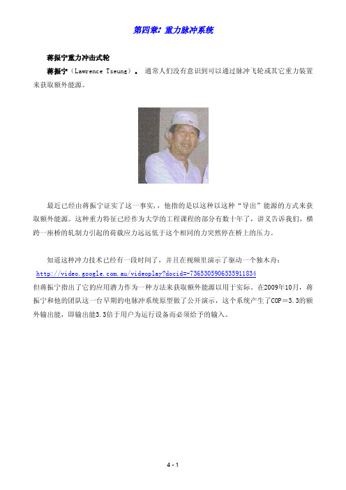
第四章:重力脉冲系统蒋振宁重力冲击式轮蒋振宁(Lawrence Tseung)。
通常人们没有意识到可以通过脉冲飞轮或其它重力装置来获取额外能源。
最近已经由蒋振宁证实了这一事实,,他指的是以这种以这种“导出”能源的方式来获取额外能源。
这种重力特征已经作为大学的工程课程的部分有数十年了,讲义告诉我们,横跨一座桥的轧制力引起的荷载应力远远低于这个相同的力突然停在桥上的压力。
知道这种冲力技术已经有一段时间了,并且在视频里演示了驱动一个独木舟:.au/videoplay?docid=-7365305906535911834但蒋振宁指出了它的应用潜力作为一种方法来获取额外能源以用于实际。
在2009年10月,蒋振宁和他的团队这一台早期的电脉冲系统原型做了公开演示,这个系统产生了COP=3.3的额外输出能,即输出能3.3倍于用户为运行设备而必须给予的输入。
蒋振宁正忙于进一步开发这种装置,因为他打算造一台超过数千瓦输出能量的装置。
此设备的背后是蒋振宁有“导出”理论,他建议这一简单的配置以证明其工作原理。
他介绍了一个转子的案例,转子有两个沉重的重物包含在圆桶中附着于转子:在圆盆转动时,球在管的长度里落下。
在一端,管子的刚性保护帽使得球撞击产生巨大的冲力。
管子的另一端衬有衬垫缓冲冲力,导致冲力的净失衡并维持旋转。
YouTube上有一个原型实施,但执行得并不足够,五分钟后圆盘停止旋转。
YouTube视频位于:/watch?v=zykButGc22U&feature=related而这个特殊设备有两个重大问题。
首先,管子旋转太慢而难以有效地在引力作用下重下落时在冲刺之前加速,重物只是轻轻地滚下一个小斜坡,没有形成很大的冲力。
其次,以轮子的尺寸来说重物太小,而且在轮子缓慢转动时只有两个重物相隔如此远地提供冲力。
一个人做了个十英尺的版本,它不断旋转十个月的时间之后,他的妻子坚持将其拆开,因为它太嘈杂了。
我会给出一些修改车轮的建议,因为蒋振宁太忙于开发他的COP>1的脉冲实施了。
贝塔电容测试仪手册Handbook_Capscan_KG2000_English

e d I s s u e /R e v : 5CapScan 2000Eurofast DeviceNet connector interfaceINSTRUCTION HANDBOOK(for suitably qualified personnel only)Manual Part Number: MAN/E1321-5053 • Revision 5 • © Copyright November 2004Beta LaserMike Inc.8001 Technology Blvd.Dayton, OH 45424USABeta LaserMike Limited Stirling RoadCressex Business Park Buckinghamshire High Wycombe UKBeta LaserMike Asia PacificRoom 606, Suncome Liauw’s Plaza No. 738 Shangcheng Rd.Shanghai 200120,P.R. Chinae d I s s u e /R e v : 5ContentsEuropean Commission Requirements....................................................................3Declaration of Conformity........................................................................................4Safety information.....................................................................................................5Introduction................................................................................................................5Mechanical installation.............................................................................................6KG2008 Dimensions - mm (inches).............................................................................7KG2016 Dimensions - mm (inches).............................................................................8KG2025 Dimensions - mm (inches).............................................................................9KG2050 Dimensions - mm (inches)...........................................................................10KG2065 Dimensions - mm (inches)...........................................................................11Electrical installation...............................................................................................12Electronics module connector panel..........................................................................12Profibus Gland Connections......................................................................................13Earth (ground) connection..........................................................................................13Threading the conduit (KG2008 model only).............................................................14Termination of Eurofast connectors...........................................................................15RS232 communications..........................................................................................17RTS.............................................................................................................................17CTS.............................................................................................................................17Connecting CapScan to a computer or terminal.......................................................17Non continuous data transmission.............................................................................18Continuous data transmission....................................................................................21Analog outputs............................................................................................................23Profibus communication........................................................................................26General information....................................................................................................26Profibus information specific to CapScan 2000.........................................................34DeviceNet communication......................................................................................37DeviceNet Configuration via RS232..........................................................................37Data Format and Units...............................................................................................38Identity Object (DeviceNet Class = 1)........................................................................39DeviceNet Object (DeviceNet Class = 3)...................................................................40Assembly Object (DeviceNet Class = 4)....................................................................41Connection Object (DeviceNet Class = 5).................................................................43Parameter Object (DeviceNet Class = 15)................................................................44FFT Object (DeviceNet Class = 100).........................................................................47DeviceNet communication specific to CapScan........................................................53CANopen communication.......................................................................................57General and Specific CANopen information..............................................................57Setting jumpers on main PCB................................................................................67Calibration................................................................................................................68KG2025 / 2050 / 2065 connections...........................................................................68KG2008 / 2016 connections and basic procedure....................................................69Options.....................................................................................................................73Determining which options have been purchased.....................................................73Indicator KI1000.........................................................................................................74In-head FFT mode.....................................................................................................75Fast analog output mode...........................................................................................75High Bandwidth Option..............................................................................................75Maintenance.............................................................................................................75Troubleshooting......................................................................................................76Specification............................................................................................................77Index. (79)e d I s s u e /R e v : 5European Commission Requirementse d I s s u e /R e v : 5Declaration of ConformityDeclaration of Conformitye d I s s u e /R e v : 5Safety informatione d I s s u e /R e v : 5see Specification/Environmental Conditions .xxFor dry installation 2 caps essential.For submerged installation 1optional cap (inlet side) used for For submerged installation 1 optional cap (inlet side) used for bubble clearance.Detachable end for threading (KG2008 only).See Electrical installation for details.Electronics box0.75m (30 in) Flexible conduit(not applicable to KG2050 & KG2065)Mounting collars(not applicable to KG2050 & KG2065)The neck of the KG2008tube can be mounted to the trough (instead of using the mounting collars).Measuring tubeOptional special caps.See Options table below.e d I s s u e /R e v : 5e d I s s u e /R e v : 5e d I s s u e /R e v : 5l e x i b l e t u b e m i n b e n d r a d (3.94)100with caps 742(29.21)without caps60(2.36)adjustable:g f o r p i p e(830 22.5(0.89)∅e d I s s u e /R e v : 5Ø121(476Compression fitting for pipe Ø28(1.1)Water inletcap (optional)19.75(0.77)140.4(5.52)38(1.5)263(10.351237(48.7) with caps1158(45.59) withoutElectrodes bore max Ø612(24.094 holes M6 equi-spaced 104(4.09) P.C.D.91(3.58)162(6.38)230.5(9.07)F o r d e t a i l s s e e o t h e r K G d i m e n s i o n d r a w i n g se d I s s u e /R e v : 5e d I s s u e /R e v : 5* Problems may occur with longer cables. Refer to Specification/RS232 Cable length .All connections except the Profibus are made by IP67 MIL spec. connectors. The Profibus connection is made with PCB mounted screw terminals with the cables fed through IP68 EMC glands.Profibusin Profibus outEarth (ground)studC analog fast (option)D analog slowE analog comm.F n/c Gn/cPin Function 1Drain 2V+ (24V)3V- (24V –rtn)4CAN High 5CAN LowA GNDB TXDC RXD D RTS *E CTS *Fn/ce d I s s u e /R e v : 511. Insert washer with smaller hole over cores.12. Clamp braid between washers and cut off any excess braid.13. Screw on the gland cover nut and tighten.14. Remove any excess plastic and cores.15. The cores leading to the screw terminals (Profi input and Profi output) should beas short as possible. Cut cores to exact length.CoresWasher with smaller holeBraid (to be clamped in-between washers)Washer with bigger holeRubber insertGland cover nutNote: Cable colours may vary.e d I s s u e /R e v : 5Disconnect power connector (connector 3) from electronics box.Loosen 4 screws on electronics box lid and remove lid.Use antistatic wristband or touch casing to discharge any static electricity.The following few steps describe the removal of all 3 wires from electronics box and the removal of gland A from these wires.Disconnect all connectors leading from conduit to PCB in electronics box.On the outside of the electronics box unscrew cable clamp body from electronics box.Pull the guard wire out of the electronics box, earthing collet and cable clamp body.If Screening clamps are used, simply push the wires through the earthing collet and through the cable clamp body.It is recommended that this part of gland is not disconnectedfrom electronics box.Earthing colletCable clamp bodyFig 2:guard wireGland nut for securing gland body to trough or bulkhead.Gland (B)bodyGland (A)connecting conduit toelectronics box.Fig 1:Gland clamping nut for securing conduit to gland body.not needed for thisconnection.Connectors(BNC connectors are shown here, but Screening clamps may also be supplied instead)e d I s s u e /R e v : 58. Screw the clamp screw (together with cable clamp) onto the connector body.Use tool for final tightening.9. Insert plastic insulator into connector body ensuring that the cut-out in theinsulator lines up with the internal groove in the connector body.Connector bodyTop ofscreen clampClamp screwConnector bodyCutoute d I s s u e /R e v : 5Screw on Connector to Connector body as shown on photo below.The cable is now correctly terminated and ready for use.ConnectorWiresConnectorConnector bodye d I s s u e /R e v : 5e d I s s u e /R e v : 5e d I s s u e /R e v : 5e d I s s u e /R e v : 5e d I s s u e /R e v : 5e d I s s u e /R e v : 5e d I s s u e /R e v : 5e d I s s u e /R e v : 5e d I s s u e /R e v : 5e d I s s u e /R e v : 5e d I s s u e /R e v : 5e d I s s u e /R e v : 5e d I s s u e /R e v : 5e d I s s u e /R e v : 5e d I s s u e /R e v : 5e d I s s u e /R e v : 5e d I s s u e /R e v : 5e d I s s u e /R e v : 5e d I s s u e /R e v : 5Example of a typical FFT operation1) Select the required FFT sampling frequency (parameter 102), and thenumber of FFT points (parameter 100).2) Set the line speed (parameter 3).3) To start the FFT operation set the SF bit in the output control word to 1. NB itis advised to wait a few master cycles before resetting this bit to ensure thestart command was recognised.4) Wait for the FC bit in the input data word base+3 to be set. This indicatesthat the FFT operation has been completed and the data is ready.5) Valid data can now be read from parameters 105 and 110 to 129 indicatingthe largest 20 amplitudes. Also, all of the FFT result data can be read inblocks using parameter 104 to control the transfer see below.Block transfer of FFT dataWhen FFT data is valid it can be read out from the gauge in blocks of 9 wordsat a time. This data is located in the input data words base+8 to base+16. Thedata in this area does not change until a new block is requested. A block of datais requested by outputting the PKW data words (PKE/base+0 to PWE2/base+2)set up to write parameter 104 with the required block number as the parametervalue (PWE2/base+2). The request is completed when the input PKW dataindicates a response to the write word request and the required block number isreturned as the parameter value (PWE2/base+2). When the request iscompleted the input data words base+8 to base+16 will contain the requestedFFT data block.5:veR/eussIdee d I s s u e /R e v : 5e d I s s u e /R e v : 5e d I s s u e /R e v : 5e d I s s u e /R e v : 5e d I s s u e /R e v : 5e d I s s u e /R e v : 5e d I s s u e /R e v : 5Connection Object (DeviceNet Class = 5)The Beta LaserMike gauges fully implement the DeviceNet ‘group 2 only, pre-defined master/slave connection set ’.Each gauge fully supports concurrent explicit message, polled IO, bit-strobeIO, and Change-Of-State (COS) / Cyclic connections.COS/Cyclic connections may be acknowledged or unacknowledged, and all theassociated production/consumption paths, path lengths, production triggers,and initial communication characteristics are configured appropriately as per thepre-defined master/slave connection set instantiation rules.Please note the following points regarding the DeviceNet pre-definedmaster/slave connection set specification:1. COS/Cyclic connections are mutually exclusive (they are the sameconnection but with a different production trigger mechanism).2. The master can only produce output data over the polled connection, but maydo so using the polled, change-of-state, or cyclic mechanisms according tohow the connection was instantiated.3. When the polled connection and the COS/Cyclic connection are instantiatedat the same time, or the polled connection is instantiated followed by theCOS/Cyclic connection, then the master supplies output data to the gaugeusing the polled connection, and the gauge provides input data to the masterusing both the polled connection and the COS/Cyclic connection. This isbehaviour defined in the DeviceNet specification.4. The bit-strobe connection provides 1 bit of output data from the master toeach slave. The Beta LaserMike gauges make no use of this bit, but willrespond with appropriate bit-strobe input data (each response is limited to 8-bytes, as per the DeviceNet specification).Normally the master control computer ’s DeviceNet drivers/library will take careof establishing connections according to parameters supplied. See theDeviceNet specification for exact details regarding attributes of the connectionclass and connection instances. However, it is worth mentioning here that theBeta LaserMike DeviceNet implementation fully supports the followingconnection instance attributes (where appropriate to the connection type):1. Expected packet rates: to a 10ms resolution.2. ACK retry limit – for acknowledged COS/Cyclic connections.3. ACK timeout: for acknowledged COS/Cyclic connections, to a 10ms resolution.4. Production inhibit time: for COS connections, to a 10ms resolution.5. Watchdog timeout action: including: time out (IO only), auto-delete, auto-reset (IO only), and deferred delete (explicit message only).e d I s s u e /R e v : 5e d I s s u e /R e v : 5e d I s s u e /R e v : 5e d I s s u e /R e v : 5e d I s s u e /R e v : 5e d I s s u e /R e v : 5Attempting to access a member at index 0 for any of the FFT arrays will returnan ‘invalid parameter error’. DeviceNet reserves member index 0 for analternative use not supported by the Beta LaserMike gauges.A read request for zero members will return an ‘invalid parameter’ error.A read request for which the starting index is beyond the end of the spike arrayor beyond the end of the discrete arrays will return an '’invalid parameter’ error.Attempting to read from the discrete arrays before an FFT has been performedwill return an ‘invalid parameter’ error. It is possible to begin reading the FFTdata as soon as the first FFT has started, but the returned data will bemeaningless; wait for the ‘FFT complete’ bit to transition from a 0 to a 1 beforebeginning collection of FFT results. It is possible to read spike informationbefore an FFT has been performed, but the returned data will be all zero.A master application should use the ‘get member extended’ service (or ‘getattribute’ in association with the FFT_MEMBER_IDX andFFT_MEMBER_COUNT attributes), according to the maximum number of bytesthat can be accepted by the master in an explicit message response.Remember to account for any explicit message header and ‘get memberextended’ protocol response bytes when calculating the maximum number ofvalues that may be requested. The gauge will respond with a maximum of 64FFT results for a single request, no matter what format they are requested in.When determining how many values to obtain in a single request, the systemdesigner should take the master’s response buffer size and CAN bus prioritiesand bandwidth into account. Requesting large blocks of data from the gaugemay prevent devices with higher MacId’s from transmitting IO data. Becauseeach explicit message fragment must be acknowledged by the master, thegauge cannot transmit blocked FFT results in a back-to-back manner andtherefore the impact on other DeviceNet servers may not be as significant asmight otherwise be expected. Internally, the CapScan assigns higher priority toIO data production than to explicit message production and therefore anysolicited or Cyclic / Change-Of-State IO messages will be transmitted in-between the explicit message fragments forming the blocked FFT results.Note that a request to start an FFT (using the ‘Output Control Word’) mayappear to fail if there is no product within the measuring gate of the gauge. Thisis normal gauge behaviour and not a function of the DeviceNet protocolimplementation.5:veR/eussIde。
天启测量系统使用手册说明书

广东科力达天启RTK测量系统使用手册第二版广东科力达仪器有限公司二○二二年一月目录目录 (1)第一章概述 (1)§1.1引言 (1)§1.2产品功能及亮点 (1)第二章天启测量系统介绍 (4)§2.1整体介绍 (4)§2.2天启主机介绍 (5)§2.2.1主机外型 (5)§2.2.2结构与接口 (6)§2.2.3按键和指示灯 (7)§2.3主机按键与液晶设置 (7)§2.3.1主界面 (7)§2.3.2设置工作模式 (9)§2.3.3设置数据链 (12)§2.3.4系统配置 (15)§2.3.5主机控制 (20)§2.3手簿介绍 (21)§2.3.2键盘及功能介绍 (21)§2.4.2蓝牙连接 (23)§2.5主机配件介绍 (25)§2.5.1仪器箱 (25)§2.5.2电池及充电器 (26)§2.5.3差分电台天线 (27)§2.5.4数据线 (27)§2.5.5其他配件 (27)第三章仪器架设与配置 (28)§3.1静态作业 (28)§3.2RTK作业(内置电台1+1模式) (30)§3.2.1内置电台基站架设 (30)§3.2.2启动基准站 (31)§3.2.3架设移动站 (33)§3.2.4设置移动站 (34)§3.3RTK作业(网络1+1模式) (36)§3.3.1基准站和移动站的架设 (36)§3.3.2基准站设置 (36)§3.3.3移动站设置 (38)§3.4RTK作业(网络CORS模式) (41)§3.4.1移动站的架设 (41)第四章常见功能使用 (44)§4.1点测量 (44)§4.2点放样 (46)§4.3成果数据导出 (48)§4.4惯导功能使用 (50)§4.5WebUI网页配置 (52)§4.6固件升级 (54)4.6.1数据线升级 (54)4.6.2WebUI网页升级 (56)4.6.3工程之星在线升级 (58)§4.7天线高量取方式 (59)附录A天启测量系统技术指标 (60)附录B H6手簿技术指标 (63)附录C联系方式 (64)第一章概述阅读本章,您可以简单了解科力达公司及天启测量系统§1.1引言欢迎使用广东科力达仪器有限公司产品。
5.7. Compass 使用手册
4
1.6 选择了DB,就在 (1)湖面上点击compass或
sbpchem
点 击 Daily Operation 就 可以。 然后就出现如下画面
sbpchem
开始Compass。 开始Compass并且背景为 白色。
5
在上一步开始了 Compass,就会出现如下的信息窗口。 psmp1 communication is not running. Do you want to start it?(yes/no) 输入‘yes’点击 Enter Key Compass就正式开始了 1.7. Enter COMPASS user : Enter Password : 上各输入 “SYSTEM” 就会转换成 COMPASS 基本窗口画面。
38
设定基准测量值及警报值
点击 点击
点击
39
监控倾向值曲线
1.设定限制指
点击
在Setup设定的值 PLOT 显示。
40
监控频率值曲线
Reference值设定: 测量基准震动值、定义时间及 测量 Resolution
设定报警值: 对比基准频谱 设定Alert及 Danger 值
41
画面编辑器
MVE(Machine View Editor)是在画面 上制作设备图的编辑器
1.8 开始Compass 的另一种方法
点击xterm就会出现右侧画面。
6
在上页的画面中
1.9
COMPASS Command Prompt 状态 (cdl:/usr/compass 21 >)下 为了执行COMPASS DatabaseTyping“compass sbpchem”。
pol communication is not running. Do you want to start it?(yes/no)
abb 测量与控制系统 威尔泰尔无线传感系统开机指南说明书
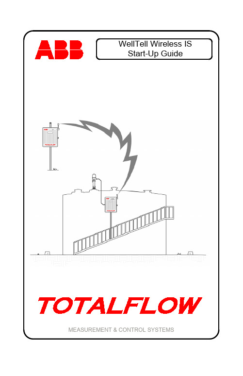
WellTell Wireless ISStart-Up Guide MEASUREMENT & CONTROL SYSTEMSIntellectual Property & Copyright Notice©2009 by ABB Inc., Totalflow Products (“Owner”), Bartlesville, Oklahoma 74006, U.S.A. All rights reserved.Any and all derivatives of, including translations thereof, shall remain the sole property of the Owner, regardless of any circumstances.The original US English version of this manual shall be deemed the only valid version. Translated versions, in any other language, shall be maintained as accurately as possible. Should any discrepancies exist, the US English version will be considered final. ABB is not liable for any errors and omissions in the translated materials.Notice: This publication is for information only. The contents are subject to change without notice and should not be construed as a commitment, representation, warranty, or guarantee of any method, product, or device by Owner.Inquiries regarding this manual should be addressed to ABB Inc., Totalflow Products, Technical Communications, 7051 Industrial Blvd., Bartlesville, Oklahoma 74006, U.S.A.1IntroductionFor installation in Classified Hazardous Locations: Please consult the User’s Manual, the drawing(s) referenced on the unit’s name plate, and any national and local codes of jurisdiction.This is a quick start guide designed for typical installations only. It is recommended that inexperienced technicians consult the Totalflow ® WellTell Wireless User’s Manual for more detailed information while doing the installation and start-up. Scan through the guide to see what information is available before beginning the installation. If there are questions that are not answered in this guide or other documentation, call a Totalflow representative or call the number listed on the back page of this guide.Unpack and inspect the WellTell-X and the WellTell-IS and any other optional equipment, if purchased. Inspect all parts and pieces for damage and missing or incorrect components.Before BeginningThe WellTell-IS system is comprised of two parts (see Figure 1): the host (WellTell-X) and the intrinsically safe (IS) barrier client (WellTell-IS). The host, WellTell-X, is generally installed in the site controller (XFC or XRC). The IS barrier client, WellTell-IS, is installed near the LevelMasterapplication.Figure 1. Basic Setup2Basic InstallationThe following information covers the initial installation of the WellTell-X host at the site controller (XFC/XRC), the installation of the WellTell-IS client near the LevelMaster application and the final application configuration and test at the site controller.The instructions are broken down into segments that cover the mechanical and electrical installation, along with the configuration of the system. It is assumed that this installation is taking place within either a 6400 or 6700 enclosure. Step 1 WellTell-IS Mechanical InstallationThe mechanical installation for both the WellTell-IS client and WellTell-X host is the same. Use the following instructions to accomplish the task. 1A Position pipe saddle on meter run. Select a location thatallows easy user access and is close to the equipment.Temporarily attach the saddle on the meter run pipe using U-bolt and associated hardware. 1B Screw 2” by 40” mounting pipe into saddle (see Figure 2).Place the level against pipe and vertically align. Adjust pipe,mounted in saddle, until vertical alignment is achieved. Aftervertical alignment, securely tighten 2” by 40” pipe in saddle.Tighten the saddle mounting bolts. Ascertain that the pipe issecurely installed in the saddle. 1CPosition enclosure on 2: mounting pipe and secure in placewith two U-bolts, flat washers, lock washers and two 9/16”bolts (see Figure 3).Figure 2. Pipe and Saddle Mount3Figure 3. Pipe Mounted 6400/6700 Enclosure Step 2 WellTell-X InstallationThe WellTell-X host unit is mounted in a communication tray (generally at the factory) and is designed to be installed in a Totalflow 6400 or 6700 enclosure (see Figure 4).At the top of the enclosure is the area where communication devices are installed. This area is referred to as the communication compartment (see Figure 5). All communication equipment is secured to the communication tray and slid into this compartment. The WellTell-X is mounted to standoffs on the communication tray and then slid into the communication compartment.4Figure 4. Communication TrayFigure 5. Communication Tray Installed in 6700 Enclosure5 Step 3 WellTell-X Host Communication WiringNOTE: If the unit came pre-configured from the factory, ignore thefollowing wiring instructions.Wiring of the WellTell-X host to a parent device (XFC/XRC) is fairly simple. In the example (see Figure 6), an XFC-195 board is used as the parent meter. If the application involves something other than the XFC-195, please check the meter pinouts before proceeding.Additionally, the following example uses COM 2 of the XFC. COM 1 is often defaulted for communication with a remote device (radio, modem, etc.). Wiring is simplified by the use of pre-wired cable (2100759-004)designed specifically for the WellTell-X device.Figure 6. Wireless Host Wired to COM 2 of XFC-195 Step 4 Configuring COM 2 for the LevelMaster ApplicationAfter completing the electrical wiring for the WellTell-X to COM 2 of the flow computer, the user needs to configure the COM 2 communication port.NOTE: In Figure 6, COM 2 (XA2) must have an RS-485 module(2015193-002) inserted.Figure 7 walks the user through the steps (A, B and C) to configure COM 2 for the LevelMaster application.6Figure 7. COM 2 Configuration for LevelMaster SetupWellTell-IS WiringElectrical wiring at the WellTell-IS (client) is done in two basic steps: powering the unit and wiring the RS-485 to the LevelMaster sticks. Step 5 WellTell-IS Client Electrical WiringThe WellTell-IS client can be mounted near or at the top of the storage tank. It should be mounted in a Division 2 or non-hazardous location. However, this can be a minimum of 10’ away from any opening (outside of the Division 1 areas), and a short piece of cable can be run to the LevelMaster itself.The WellTell-IS client also has an onboard battery charger to maintain the charge on a 12 VDC lead-acid battery. Figure 8 illustrates the most common way to provide power to the WellTell-IS.7Figure 8. Powering of the WellTell-IS Step 6Wiring the LevelMaster Sticks to the IS BarrierThe second part of the electrical installation for the WellTell-IS is the wiring of the LevelMaster sticks to the IS barrier on the WellTell-IS. Figure 9 illustrates how this is achieved.Figure 9. Wiring LevelMaster Sticks to the IS BarrierSystem ConfigurationStep 7Configuring WellTell-XIn a similar fashion to configuring the meters for the COM 2 port, the user must also configure the WellTell-X radio.To configure the WellTell-X (or the WellTell-IS) radio, the user must have the WellTell Wireless Utility (WWU) program and a typical 9-pin to 9-pin (male DB9 to female DB9) cable. The cable connects between a laptop and the maintenance connector of the WellTell-X.7A Configure WellTell-X Security.WWU supports two levels of access: Restricted Use andAdmin (lower left on the System Config tab). Restricted Usegives the user access to the basic setup parameters that aremost often used (i.e., Network ID, FR Channel, etc.). Lesserused parameters (i.e., Encryption Key, Range Refresh, etc.)are grayed out, if Restricted Use is used. Normal setup doesnot require Restricted Use. These lesser parameters can beaccessed through Admin. Admin is achieved by entering thepassword. The factory password is ‘0000.’As opposed to providing an in-depth, screen-by-screen explanation of the WWU utility, the opening screen is presented to the user along with references to the various available tabs that contain relevant parameters on each of their corresponding screens (see Figure 10).7B System Config Tab.Set the parameters as shown within Figure 10.7C Radio Config Tab.Parameter Field ValueMode ServerNetwork ID 1 (Must match Client)RF Channel Anything between 16 and 47 (must match Client)Baud Rate 9600Delivery Mode BroadcastRF Mode AcknowledgeDuplex Mode Half Duplex7D Network View Tab.Leave default values.8Figure 10. WWU Main Screen7E PC Port Tab.Parameter Field ValuePort COM 1 (Communication port of laptop PC)Baud Rate 9600Data Bits 7 bit for LevelMaster – Required for Snoop feature Parity Even – Required or Snoop featureStop Bits 1Tab.7F FlashLoaderLeave default values.Tab.7G TestLeave default values.9Step 8 Configuring WellTell-ISJust as the host radio, WellTell-X, was configured, it is necessary to configure the WellTell-IS client radio.As before, it is necessary to have the WWU program and a typical 9-pin to 9-pin (male DB9 to female DB9) cable. The cable connects between the laptop and the maintenance connector to the WellTell-IS.The opening screen for the WellTell-IS client radio is similar to the opening screen for the WellTell-X host, with the exception of a display that states that this is a Wireless Client Server as opposed to a Wireless Host Server.Rather than providing an in-depth, screen-by-screen explanation of the WWU, please refer to Figure 10 to view the available tabs. As presented in the previous section, the following details each individual tab available to the user and the corresponding parameter fields and values that must be entered therein.8A System Config Tab.Set the parameters as shown within Figure 10.8B Radio Config Tab.Parameter Field ValueMode ClientNetwork ID 1 (Must match HostRF Channel Anything between 16 and 47 (must match Host)Baud Rate 9600Delivery Mode BroadcastRF Mode AcknowledgeDuplex Mode Half Duplex8C Network View Tab.Leave default values.8D PC Port Tab.Parameter Field ValuePort COM 1 (Communication port of laptop PC)Baud Rate 9600Data Bits 7 bit for LevelMaster – Required for Snoop featureParity Even – Required or Snoop featureStop Bits 18E FlashTab.LoaderLeave default values.1011 8F Test Tab.Leave default values. Step 9 Final Configuration at the Site Controller (XFC/XRC)With the WellTell-X host and the WellTell-IS client both installed and configured, the last step is to configure the site controller (XFC/XRC at the host end) for the LevelMaster application. There is no difference in the configuration of the LevelMaster application due to the presence of the WellTell products. LevelMaster is instantiated and configured as it would be without the WellTell products.With the system up and running, the WellTell-X host display looks similarto Figure 11.Figure 11. WellTell-X (Host) DisplayThe antenna symbol is on. The “$” symbol is always active on the WellTell-X or host server. The “-“ is the system heart beat and blinks continuously. The blink slows down whenever the radio is dead or not connected. The “F3” in the upper right of the display denotes that this is a host server (WellTell-X). The main area of the display scrolls through several parameters: baud rate, temperature, channel, etc. For more information on the display, refer to the appropriate appendix.LCD Display and AnnunciatorsFigure 12. LCD DisplayDescription of Standard Displays (Annunciators)Envelope Indicates “Snoop” mode (i.e., processor is “snooping” thedata stream).Tx/Rx Indicates activity on the processor’s UART port.Antenna The Host Server (WellTell-X) annunciator is always on.The Client (WellTell-IS or WellTell-IO) is only on when theClient is ‘synced’ to a Host.Signal Strength A three section “progress bar” indicating incoming signalstrength between the Host and the Client.Battery Strength A four section “progress bar” indicating incoming signalstrength between the Host and the Client.Arrows The arrows represent up, down, left and right for a total offour. These arrows describe the Routing Matrix of theWellTell Product. This Routing Matrix connects themicroprocessor (also referred to as the Maintenance Port)to either the radio or to the RS485 device port. In PassThrough mode, the Device Port is connected directly tothe radio while the microprocessor can be enabled to“snoop” data from either the Device Port or the radio.More on this topic can be found in the WWU Help Files.When the UP arrow is on, the Microprocessor can snoopthe Device Port. If the UP arrow is not on, themicroprocessor can snoop the radio. Snoop is onlyoperational in Pass Though mode (i.e., the Left and Rightarrows are lit).The DOWN arrow being on informs the user that themicroprocessor is being connected in the Routing Matrix.When the RIGHT arrow is on, this depicts that the radio isbeing connected in the Routing Matrix.The LEFT arrow being on depicts that the Device Port(RS485) is being connected in the Routing Matrix.An example of the Routing Matrix might be having theDevice Port (RS485) connected directly to the radio (PassThrough mode). In this configuration the LEFT and RIGHTarrows would both be on.F1 – F5 Annunciators F1 I.S. Barrier Client indicator (WellTell-IS) F2 I/O Client indicator (WellTell-IO)F3 Host Server indictor (WellTell-X)F4 Reserved for future useF5 Test mode indicator[ ] Right and LeftBracketsIndicate activity on the Maintenance (processor) port. $ Always active on the Host and inactive on the Clients.M Activates whenever a cable is connected to theMaintenance port.- The ‘dash’ or ‘underscore’ is the system heartbeat. It12blinks off and on continuously. The blinking slowswhenever the Radio is dead or not connected.Description of Standard Displays (Alpha/Numeric Portion)SLEEP When power drops below 10.5VDC the Host Server willdetect the low voltage and enter a “SLEEP” mode.Host Server and the I/O and Barrier Clientb Ex: 9600 b Baud rate displayed in Numeric section.n Ex: n 1 Network ID displayed in Numeric section.ch Ex: ch 2 Channel displayed in Numeric section.b Ex: b 12.3 Battery voltage displayed in Numeric section.t Ex: t 72.1 Temperature displayed in Numeric section.I/O and Barrier Clients (Not Applicable to the Host Server)c Ex: c 0 Charger voltage.L Ex: L .5 Lithium cell voltage.Barrier Clients Only (Not Applicable to the Host Server or the I/O Client) o Ex: o .0 Overload voltage.i Ex: i .0 Intrinsically safe voltage.S Ex: S 4.5 Supply voltage supervisory.13ABB Inc.Totalflow Products7051 Industrial Blvd.Bartlesville, Oklahoma 74006Tel: USA (800) 442-3097International 001-918-338-4880。
拓普康仪器的使用电子教案

Land Management & Cadastral Surveying
(2)设置好全站仪的通讯参数。 (3)操作
①全站仪操作: 进入“MENU”菜单 → 存储管 理 → 数据通讯 → 接收数据 → 坐标数据 → 输入 接收的坐标文件名, 点击“是”等待数据接收。
②计算机操作: 运行“T-COM”通讯软件,进入主菜单, 点击 图标,将通讯参数与全站仪上通讯参数设置一致
4)当输入测量次数后,仪器按设置次数观 测并显示平均值,按F1键可终止连续测距, 当测距正在进行时,再按F1键又转变为连续 测量模式。 2020/6/21
Land Management & Cadastral Surveying
说明: (1)温度、气压改正可通过“大气改正值 的设置”进行。 (2)使用与拓普康配套的棱镜,其棱镜常 数为零,如果使用其它的棱镜,应测定棱镜 常数并在“设置棱镜常数”中进行设置,一 旦设置了不重新修改,棱镜常数将保持不变。 (3)可根据需要设置为“C:粗测”、“F: 精测”、“T:跟踪”以及“连续测量”模 式,在“连续测量”下模式,显示的结果为 其平均值。
2020/6/21
Land Management & Cadastral Surveying
5)偏心观测 角度偏心测量 距离偏心测量 平面偏心测量 圆柱偏心测量 (1)角度偏心测量 将棱镜安置在离仪器到目标点 A0相同水平距离的另一个合适 的目标点上进行测量。 如果测量地面点A1的坐标:应 输入仪器高/棱镜高 如需测量点A0的坐标:只需输 入仪器高(设置棱镜高为0)
2020/6/21
Land Management & Cadastral Surveying
实验仪器仪表科尔帕默使用方法
实验仪器仪表科尔帕默使用方法
科尔帕默(Coriolis meter)是一种用于测量流体质量流量的仪器,下面是其使用方法:
1. 安装:首先需要将科尔帕默根据其安装说明安装在管道上,并且保证管道的进出口处均为平直的段落。
2. 启动:启动仪器之前需要确认其电气和机械系统都处于正常状态,然后打开流体流动的阀门,确保流体进入科尔帕默内部的管道中。
3. 测量参数设置:进入仪器的参数设置界面,设置好需要测量的流体类型、流量范围、温度、压力等参数。
4. 测量:通过输入仪器所需的操作指令,开始进行测量。
科尔帕默通过测量流体在仪器内部的弯曲变化,得出流体的质量流量和体积流量等参数。
5. 数据处理:获得测量结果后,需要进行数据处理和分析,得出需要的参数和统计量,比如质量流量平均值、流量变化率等。
6. 系统维护:按照科尔帕默的维护手册进行定期的清洁、校准等维护操作,保证仪器的准确性和性能。
COMPASS 5000基本操作手册-PK
COMPASS 2000操作使用手册目录目录 (1)一.COMPASS概述 (7)1.COMPASS优点: (7)2.COMPASS主要具有三个主要的功能,同时还有一个功能强大的测绘工具。
(7)3.COMPASS系统还有如下功能: (8)4.COMPASS还拥有如下一些实用工具 (8)二.简要的操作指南 (9)1.To open a wellpath(打开井眼): (9)2.To view wellpath:(查看井眼) (9)3.Open another wellpath(打开其它井眼) (9)4.To Create a plan:(创建一个井的设计)[参看设计模块] (9)5.To edit a survey:(编辑测量) [参看测量模块] (9)6.To view a wellpath’s survey program:(查看井眼轨迹的测量组合) (10)7.Anticollision(防碰)[参看防碰模块] (10)四Compass数据结构 (10)4。
1 working at the Company level (10)4.2 working at the project level (31)4.3 Working at the site level (35)4。
4 Working at the Well Level (38)4.5 working at the Wellbore level (42)4.6 Working at Plan design level (42)4.7 concepts (44)五planning module (44)6.Template模板 (52)7.Targets 靶区 (64)五.Survey测量...................................................................................................................... 错误!未定义书签。
安伯格操作说明
安伯格操作说明一、安伯格使用范围及配套软件:1、适用范围(1)无砟轨道长轨精调;(2)双块式无砟轨道施工;(3)有砟轨道指导捣固机作业;2、配套软件包括:(1)GRPwin 数据采集系统(2)GRP SlabRep无砟轨道专用数据处理软件(3)DTS 平顺性分析与调整量模拟试算软件(4)GRP Fidelity 系统校准软件二、轨道静态几何参数测量方法1、无砟轨道几何参数(1)绝对几何参数:轨道实测中线坐标、轨面高程及其与设计坐标和高程的偏差;偏差越小,精度越高。
(2)相对几何参数:轨距、水平(超高)及其偏差和变化率,轨向和高低偏差及长短波不平顺等;数值越小轨道越平顺。
2、精密测量三要素:(1)高精度控制网(2)精密测量仪器:徕卡全站仪+GRP轨检小车(3)熟练的测量人员:测量技能+轨道知识+软件操作3、GRP操作说明:(1)GRP1000数据采集(2) GRPwin软件:项目资料①Cp3和cp4/GRP点三维坐标及编号规则;②左右线独立设计中线;③平曲线设计参数:起点里程,交点坐标和偏角,圆曲线半径,缓和曲线长和长短链等,平换算ZH、HY、YH、HZ点坐标;④坡度表:里程、变坡点高程和竖曲线半径;⑤曲线设计超高值;⑥轨枕编码方法;(3)GRPwin软件:平曲线①首先输入起点里程,然后选择曲线要素类型,并输入每一曲线要素的起点坐标、缓和曲线长度或圆曲线半径(右转曲线半径为正值);长短链处需分为两段设计中线。
②路径:项目属性→测量文件→设计中线→平曲线(4)GRPwin软件:竖曲线①竖曲线通过切线交点定义,输入交点里程、高程和竖曲线半径。
下凹曲线半径未负;上凸半径为正;②如果变坡点处设置了竖曲线,则圆类型选择“圆";如果没有设置竖曲线(坡度代数差不大)则选择“顶点”;竖曲线起点和终点必须选择“顶点”。
③路径:项目属性→测量文件→设计中线→竖曲线④工作区间前后各两个变坡点(5)GRPwin软件:超高①输入ZH、HY、YH、HZ点的超高值,与平曲线一致;②左转曲线超高为负,右转曲线超高为正,单位为米;③路径:项目属性→测量文件→设计中线→平曲线(6)GRPwin软件:控制点①可导入文件类型:txt格式文本GSI格式文本②数据格式:点号、东坐标、北坐标、高程;字段之间用空格隔开;③路径:项目属性→测量文件→服务文件→控制点(7)GRPwin软件:项目属性①项目属性→平面和高程基准②项目属性→轨向高低基准(8)GRPwin软件:软件选项①软件选项→常规②GRPwin软件:软件选项→通讯③GRPwin软件:软件选项→限差④GRPwin软件:软件选项→数据测量⑤GRPwin软件:软件选项→全站仪(9)GRPwin软件:测量文件设置①新建测量文件后需读取小车校准参数,选择名称中含1。
野外科学试验地面气象观测规范
辐射
降水
土壤 温湿度
地面气象观测仪器 —地面气象观测仪器的一般要求
地面气象观测仪器应当是正规生产厂家 生产;准确度满足规定的要求;可靠性 高,保证获取的观测数据可信;仪器结 构简单、牢靠耐用,能维持长时间连续 运行;操作和维护方便,具有详细的技 术及操作手册。
青藏高原可可西里索南达杰站
祁连山阿柔冻融观测站
地面气象观测场环境条件要求
气象站站址在满足科学目的的同时,必须符合观测技 术上的要求,也应考虑后勤保障和维护上的便利。 观测场是取得地面气象资料的主要场所,地点应设在 能较好地反映本地较大范围的气象要素特点的地方, 避免局部地形的影响。 观测场四周必须空旷平坦,避免建在陡坡、洼地或邻 近有丛林、铁路、公路、工矿、烟囱、高大建筑物的 地方,避开地方性雾、烟等大气污染严重的地方。 观测场四周障碍物的影子应不会投射到辐射观测仪器 的受光面上,在日出日落方向障碍物的高度角不超过 5o,附近没有反射阳光强的物体。
土壤剖面的分层处理
观测站建站信息的档案
观测场的地理条件和环境背景,站点位 置和拔海,传感器型号和参数及其布设 高度和深度以,土壤剖面的照片等建站 资料应存档备案。
气象观测塔的架设
无论地面水平与否,气象观 测塔架设时要保持塔身的铅 直,横杆保持水平。 气象观测塔应有防雷装置。 固定塔身的纤绳每隔10m左右 应有一层,以保持塔的稳定 性。纤绳与塔边应在同一垂 直面上,并与地面成60º夹角。 支撑塔身和固定纤绳的的底 座要坚固。 太阳能板应面朝正南,并与 水平面成60º夹角。 数据采集箱架设在塔身的北 面1-1.5m高度处。
观测资料的检查和整编
对地面气象观测站维护时下载的观测数据应 及时进行检查和整编。检查和整编的内容包括: 检查资料序列的连续性; 检查观测资料是否出现奇异值或不合理值; 建立经初步质量控制的观测资料连续系列; 绘制各观测变量随时间的变化曲线。 原始数据和资料检查情况要归档备案。
- 1、下载文档前请自行甄别文档内容的完整性,平台不提供额外的编辑、内容补充、找答案等附加服务。
- 2、"仅部分预览"的文档,不可在线预览部分如存在完整性等问题,可反馈申请退款(可完整预览的文档不适用该条件!)。
- 3、如文档侵犯您的权益,请联系客服反馈,我们会尽快为您处理(人工客服工作时间:9:00-18:30)。
%BUBMPHHFS 0WFSWJFXAs for functionality, all of our dataloggers:Measure sensors•Process data onboard•Initiate measurement and control functions based •on time or eventControl external devices such as pumps, motors, •alarms, freezers, and valvesOperate independently of ac power, computers, •and human interactionUse our PC support soft ware to program the logger •Consume minimal power from a 12 Vdc source •Interface with on-site and telemetry devices•Perform reliably under adverse conditions•W e manufacture a complete line of dataloggers that range in size and complexity. Dataloggers vary in the supported scan rates, number and type of input/output channels, analog resolution, and analog voltage accuracy. To help customers choose the best datalogger for their application, this document describes the diff erent components of the datalogger, provides a brief sum-mary of each datalogger model available, and includes charts that compare the datalogger specifi cations and list the compatible devices.Campbell Scientifi c Dataloggers Campbell Scientifi c dataloggers are at the center of our rugged, reliable data acquisition systems. They are known for their fl exibility,precision measurements, and dependability—even in harsh, remote environments.Keyboard DisplayTh e datalogger’s keyboard display allows you to manu-ally transfer data and display sensor readings, stored values, or fl ag/port status. It consists of a 128 x 64 pixel backlit graphical LCD or eight-line numeric display and a 16-character keyboard.Our CR850, CR3000, and CR5000 have a built-in key-board display as part of their integrated package. Th e CR800 and CR1000 dataloggers use the CR1000KD, a portable keyboard display that can be carried from site to site. A keyboard display is not available for our CR200X-series and CR9000X dataloggers. ProgrammingOur contemporary dataloggers are programmed with CRBasic. CRBasic stems from the BASIC programming language. It provides special instructions for making mea-surements and creating tables of output data. CRBasic also supports algebraic and conditional expressions. Data StorageData is stored in multiple tables that can be individu-ally sized and collected. Th is storage method lets you group and store like-data in separate munication ProtocolsTraditionalTraditionally, our dataloggers use a connection-based communications protocol.PakBus®With the PakBus protocol, networks have the distrib-uted routing intelligence to continually evaluate links. Continually evaluating links optimizes delivery times and, in the case of delivery failure, allows automatic switch over to a confi gured backup route.ModbusTh e Modbus RTU protocol supports both fl oating point and long formats. Th e datalogger can act as a slave and/or master.DNP3Th e DNP3 protocol supports only long data formats. Th e dataloggers are level 2 slave compliant, with some of the operations found in a level 3 implementation. TCP/IP, FTP, and SMTPTh ese protocols provide TCP/IP functionality when a CR1000 or CR3000 is used in conjunction with an NL115, NL120, or third party serial IP device.Input/Output Connections{ CS I/O Port connectsto most of our datastorage, data retrieval,and telecommunica-tions peripherals.Power & Ground Connections pro-vide power for 12 V or 5 V peripherals and grounding points for sensors and peripherals.Input/Output Connectionsinclude analog inputs, con-tinuous analog outputs, pulsecounters, switched excitationoutputs, and digital I/O ports.These connections measure,communicate with, and powersensors and peripherals.RS-232 Serial I/OPort connectsdirectly to a com-puter or to smartserial sensors.Analog InputsAnalog inputs measure voltage levels. Th ese inputs can be confi gured to make single-ended (a voltage measure-ment compared to ground) or diff erential (the high side of a voltage output compared to the low side) measure-ments. Voltages must fall within the input voltage range of the datalogger; 2:1 and 10:1 voltage dividers are avail-able. Soft ware selectable voltage ranges let you take full advantage of the datalogger’s resolution to measure volt-age changes as small as 0.33 μV (depends on datalogger model). Sensors measured by analog inputs include thermocouples, thermistors, resistive bridges, vibrating wires, and 4 to 20 mA outputs.Continuous Analog OutputsSeveral datalogger models have continuous analog outputs, which provide voltage levels to displays or proportional controllers.Pulse CountersPulse counters measure switch closures, low level AC sine waves, or high frequency pulses. Th ey sum the number of counts over each execution interval (scan rate), and allow the determination of variables such as rpm, velocity, fl ow, and rainfall intensity. Sensors that use pulse counters include tipping bucket rain gauges, fl ow meters, and anemometers.Digital I/O PortsDigital I/O ports detect status, read SDM peripherals or SDI-12 sensors, and control external devices. Each port can be configured separately within the data-logger’s program.Power and Ground InputsPower and ground inputs allow easy connection of an energy source, typically 12 V dc nominal, to energize the datalogger. Switched 12 V terminals allow the datalogger to supply power to a peripheral only when the peripheral is being measured, thus reducing power consumption. Switched Excitation OutputsAll of our dataloggers have switched voltage excitation outputs. Th ese outputs provide programmable excita-tions for resistive bridge measurements by switching voltage on and off. Bridge measurements are the ratio of the bridge output to the excitation voltage, eliminat-ing any errors in the excitation voltage.Th e CR3000 and CR5000 also have switched current exci-tation outputs. Th ese outputs are for resistance measure-ments and are programmable over a ±2.5 mA range. Communications/Data Storage PortsTh e CS I/O 9-pin port is used to connect most of our data storage and retrieval peripherals. Connection to a laptop or PC requires an interface, typically the SC32B Optically Isolated Interface.Th e RS-232 port allows the datalogger to be connected to the PC’s serial port via an RS-232 cable—no in-terface required. On the CR200X-series, CR3000,CR5000, and CR9000X, this port is electrically iso-lated. Isolation is not provided by the RS-232 port on the CR800-series and CR1000 dataloggers.Our CR1000 and CR3000 have a 20-pin parallel peri-pheral port for connecting devices that store data on a CompactFlash card and/or communicate via Ethernet.Datalogger Descriptions (listed from smallest to largest)CR800-series Measurement and Control SystemThe CR800 series consists of measurement electronics encased in a plastic shell and an integrated wiring panel. The CR800 series usesan external power supply—typically the BPALK Alkaline Battery Pack or PS100 Rechargeable Power Supply.Design Features:• Th ese research-grade dataloggers have a custom ASIC chip that expands pulse count, control port, and serial communications capabilities. Th ey are compatible with channel expansion peripher-als and thermocouples, and support serial communica-tions with serial sensors and devices via I/O port pairs.Ideal Applications:• Wind profi ling, weather stations, ETo/agriculture, air quality, soil moisture, water level/stage, aquaculture, vehicle testing, Time Domain Refl ectometry, SCADA, water quality.Models Available: • CR800 uses the portable CR1000KD keyboard display; CR850 includes a keyboard display as part of its integrated package.CR1000 Measurement and Control SystemThe CR1000 consists of a measurement and control module and a detachable wiring panel. It uses an external power supply, usually the BPALK or PS100, and a portable keyboard display, the CR1000KD.Design Features: • Besides providing all of the design features for the CR800-series dataloggers, the CR1000 has more channels and includes a 40-pin parallel peripheral port. Th e peripheral port interfaces with the NL115 Ethernet Interface & CompactFlash Mod-ule, the NL120 Ethernet Interface, or the CFM100 CompactFlash® Module.Ideal Applications: • Fire weather, Mesonet systems, wind profiling, weather stations, air quality, ETo/agriculture, soil moisture, water level/stage, aqua-culture, avalanche forecasting, Time Domain Reflectometry, vehicle testing, SCADA, water quality.Design Features:• Th ese are our smallest and lowest-cost dataloggers. Th ree of the models include an internal spread spectrum radio, which allows the dataloggers to be used as wireless sensors.Ideal Applications: • Wireless sensors, wind energy, rural water, aquaculture, water quality.Models Available: • CR200X (no radio), CR206X (915 MHz radio), CR211X (922 MHz radio), CR216X (2.4 GHz ra-dio), CR295X (supports GOES satellite telemetry).CR200X-series Datalogger/Wireless SensorThe input channel confi guration of the CR200X-series dataloggers is optimal for measuring one or two sensors; these dataloggers arenot compatible with channel expansion devices or thermocouples. The CR200X series uses an external power supply.CR3000 MicrologgerThe CR3000 consists of a compact, integrated package with a built-in power supply, a 128 x 64 pixel backlit graphical or eight-line numeric display, and a 16-character keyboard.Design Features: • Th e CR3000 provides all of the CR1000's design features, as well as more channels, programmable switched current outputs, and remov-able terminal strips.Ideal Applications: • Eddy covariance, wind profi ling, HV AC, weather stations, vehicle testing, air quality, process control, Mesonet systems, agriculture, soil moisture, Time Domain Refl ectometry, water quality Base Options: • Sealed rechargeable battery, alkaline batteries, or low-profile (no-battery) base.CR5000 Measurement and Control SystemThe CR5000 consists of a compact, integrated package with a built-in power supply, a 128 x 64 pixel backlit graphical or eight-line numeric display, and a 16-character keyboard.Design Features:• Th e CR5000 has a sampling rate of up to 5000 Hz, an onboard PC-card slot for expanding its storage capacity, and programmable switched cur-rent outputs.Ideal Applications: • Eddy covariance, Bowen ratio, weather stations, vehicle testing, HV AC, process moni-toring and control, structural or fatigue analysis, ma-chinery testing, energy management and conservation.Base Options: • Sealed rechargeable battery or low-profile (no-battery) base.Design Features:• Th e CR9000X supports a measure-ment rate of up to 100,000 Hz, provides 180 MHz clock speed, has an onboard PC-card slot for expand-ing its storage capacity, and includes an onboard 10baseT/100baseT port. Also, the CR9000X canprovide anti-aliasing and real-time FFT capabilities by using a CR9052IEPE or CR9052DC module.Ideal Applications:• Vehicle testing, structural or seismic monitoring, or other applications that require rapid sampling or a large number of high resolution channels.Models Available: • Standard CR9000X includes the base system and slots for up to nine I/O modules; the user chooses either the lab or environmental enclosure. Th e CR9000XC includes the base system, slots for up to fi ve I/O modules, and an environmental enclosure.CR9000X Measurement & Control SystemsThe CR9000X is a large modular datalogger that consists of a base system and slots for user-specified I/O modules.Comparison Table for Smaller DataloggersComparison Table for Larger Dataloggers4FOTPS 1FSJQIFSBM $PNQBUJCJMJUZ 5BCMFCopyright © 1999, 2009Campbell Scientifi c, Inc.。
