MSP430F2618使用说明书VER4.0
MSP430使用

微机原理实验报告4&5程序与EW430 上测试通过实验班号:周五下午第二节;座位号:43目录实验目的 (2)实验任务 (2)1. 了解MSP430F1xx实验板结构,掌握MSP430F1xx实验板检测方法 (2)2. EW430开发工具的初步使用 (4)3. 掌握查看和修改寄存器、存储器、外围模块端口寄存器的方法 (4)4. 了解端口P1~P6的选择PxSEL、方向PxDIR、输入PxIN、输出PxOUT各寄存器功能 (4)5. 了解程序计数器PC(即R0寄存器)的变化规律 (5)6. 了解MSP430F149单片机结构 (6)7. (选做)学习工程空间管理项目的方法 (7)8. 学习寻址方式和指令系统 (7)9. 指令格式学习 (8)10. 调试程序练习 (9)11. 比较step into和step over的不同 (10)12. 掌握计算机中数的表示和编码 (10)13. (选做)理解计算机取指令执行指令的工作原理、以及取非法指令的结果 (10)14. (选做)理解CPU对存储器进行字操作遵循的“对准偶地址”原则 (11)实验总结与思考 (11)实验目的1.了解MSP430F1xx实验板结构,掌握MSP430F1xx实验板检测方法;2.了解MSP430单片机开发工具EW430的基本使用方法;3.掌握EW430下常用的View和DEBUG命令;4.了解MSP430F149单片机结构;5.掌握P1~P6基本输入/输出有关寄存器功能;6.学习MSP430的寻址方式和指令系统;7.了解计算机取指令、执行指令的工作过程;8.掌握DEBUG下的运行命令;9.掌握在EW430下调试程序的方法;10.掌握计算机中数的表示和编码。
实验任务1.了解MSP430F1xx实验板结构,掌握MSP430F1xx实验板检测方法电源电路:对于+3V和+5V电源,采用万用表测量,发现电压稳定,测试通过。
发光二极管:由于发光二极管是共阳极接法,所以低电平点亮。
MSP430 单片机基础知识说明书

MSP430Microcontroller BasicsMSP430Microcontroller Basics John H.DaviesAMSTERDAM•BOSTON•HEIDELBERG•LONDONNEW YORK•OXFORD•PARIS•SAN DIEGOSAN FRANCISCO•SINGAPORE•SYDNEY•TOKYONewnes is an imprint of ElsevierNewnes is an imprint of Elsevier30Corporate Drive,Suite400,Burlington,MA01803,USALinacre House,Jordan Hill,Oxford OX28DP,UKCopyright©2008,Elsevier Ltd.All rights reserved.No part of this publication may be reproduced,stored in a retrieval system,or transmitted in any formor by any means,electronic,mechanical,photocopying,recording,or otherwise,without the prior written permission of the publisher.Permissions may be sought directly from Elsevier’s Science&Technology Rights Department in Oxford, UK:phone:(+44)1865843830,fax:(+44)1865853333,E-mail:************************.You may also complete your request online via the Elsevier homepage()by selecting “Support&Contact”then“Copyright and Permission”and then“Obtaining Permissions.”Recognizing the importance of preserving what has been written,Elsevier prints itsbooks on acid-free paper whenever possible.Library of Congress Cataloging-in-Publication DataApplication submittedBritish Library Cataloguing-in-Publication DataA catalogue record for this book is available from the British Library.ISBN:978-0-7506-8276-3For information on all Newnes publications,visit our Web site at:08091011121310987654321Printed in the United States of America“To Elizabeth.”ContentsPreface (xi)Chapter1:Embedded Electronic Systems and Microcontrollers (1)1.1What(and Where)Are Embedded Systems? (1)1.2Approaches to Embedded Systems (2)1.3Small Microcontrollers (5)1.4Anatomy of a Typical Small Microcontroller (8)1.5Memory (11)1.6Software (15)1.7Where Does the MSP430Fit? (16)Chapter2:The Texas Instruments MSP430 (21)2.1The Outside View—Pin-Out (21)2.2The Inside View—Functional Block Diagram (24)2.3Memory (25)2.4Central Processing Unit (30)2.5Memory-Mapped Input and Output (32)2.6Clock Generator (33)2.7Exceptions:Interrupts and Resets (36)2.8Where to Find Further Information (37)Chapter3:Development (43)3.1Development Environment (44)3.2The C Programming Language (46)3.3Assembly Language (55)3.4Access to the Microcontroller for Programming and Debugging (57)3.5Demonstration Boards (59)3.6Hardware (64)3.7Equipment (65)viii ContentsChapter4:A Simple Tour of the MSP430 (67)4.1First Program on a Conventional Desktop Computer (68)4.2Light LEDs in C (70)4.3Light LEDs in Assembly Language (72)4.4Read Input from a Switch (80)4.5Automatic Control:Flashing Light by Software Delay (91)4.6Automatic Control:Use of Subroutines (99)4.7Automatic Control:Flashing Light by Polling Timer_A (105)4.8Header Files and Issues Brushed under the Carpet (114)Chapter5:Architecture of the MSP430Processor (119)5.1Central Processing Unit (119)5.2Addressing Modes (125)5.3Constant Generator and Emulated Instructions (131)5.4Instruction Set (132)5.5Examples (146)5.6Reflections on the CPU and Instruction Set (153)5.7Resets (157)5.8Clock System (163)Chapter6:Functions,Interrupts,and Low-Power Modes (177)6.1Functions and Subroutines (178)6.2What Happens when a Subroutine Is Called? (178)6.3Storage for Local Variables (179)6.4Passing Parameters to a Subroutine and Returning a Result (183)6.5Mixing C and Assembly Language (185)6.6Interrupts (186)6.7What Happens when an Interrupt Is Requested? (188)6.8Interrupt Service Routines (190)6.9Issues Associated with Interrupts (196)6.10Low-Power Modes of Operation (198)Chapter7:Digital Input,Output,and Displays (207)7.1Digital Input and Output:Parallel Ports (208)7.2Digital Inputs (216)7.3Switch Debounce (225)7.4Digital Outputs (238)7.5Interface between3V and5V Systems (243)7.6Driving Heavier Loads (247)7.7Liquid Crystal Displays (252)7.8Driving an LCD from an MSP430x4xx (256)7.9Simple Applications of the LCD (264)Contents ix Chapter8:Timers (275)8.1Watchdog Timer (276)8.2Basic Timer1 (281)8.3Timer_A (287)8.4Measurement in the Capture Mode (300)8.5Output in the Continuous Mode (318)8.6Output in the Up Mode:Edge-Aligned Pulse-Width Modulation (330)8.7Output in the Up/Down Mode:Centered Pulse-Width Modulation (349)8.8Operation of Timer_A in the Sampling Mode (352)8.9Timer_B (353)8.10What Timer Where? (356)8.11Setting the Real-Time Clock:State Machines (357)Chapter9:Mixed-Signal Systems:Analog Input and Output (369)9.1Comparator_A (371)9.2Analog-to-Digital Conversion:General Issues (393)9.3Analog-to-Digital Conversion:Successive Approximation (402)9.4The ADC10Successive-Approximation ADC (407)9.5Basic Operation of the ADC10 (412)9.6More Advanced Operation of the ADC10 (424)9.7The ADC12Successive-Approximation ADC (432)9.8Analog-to-Digital Conversion:Sigma–Delta (438)9.9The SD16_A Sigma–Delta ADC (446)9.10Operation of SD16_A (459)9.11Signal Conditioning and Operational Amplifiers (475)9.12Digital-to-Analog Conversion (485)Chapter10:Communication (493)10.1Communication Peripherals in the MSP430 (495)10.2Serial Peripheral Interface (497)10.3SPI with the USI (504)10.4SPI with the USCI (513)10.5A Thermometer Using SPI in Mode3with the F2013as Master (520)10.6A Thermometer Using SPI in Mode0with the FG4618as Master (526)10.7Inter-integrated Circuit Bus (534)10.8A Simple I²C Master with the USCI_B0on a FG4618 (542)10.9A Simple I²C Slave with the USI on a F2013 (549)10.10State Machines for I²C Communication (559)10.11A Thermometer Using I²C with the F2013as Master (567)10.12Asynchronous Serial Communication (574)10.13Asynchronous Communication with the USCI_A (581)x Contents10.14A Software UART Using Timer_A (590)10.15Other Types of Communication (599)Chapter11:The Future:MSP430X (601)11.1Architecture of the MSP430X (601)11.2Instruction Set of the MSP430X (607)11.3Where Next? (614)11.4Conclusion (617)Appendix A:Kickstarting the MSP430 (619)A.1Introduction to EW430 (619)A.2Developing a Project in C (621)A.3Debugging with the Simulator (627)A.4Debugging with the Emulator (630)A.5Developing a Project in Assembly Language (633)A.6Tips for Using EW430 (636)A.7Tips for Specific Development Kits (640)Appendix B:Further Reading (645)Books and Articles (645)Newsletters,Magazines,and Journals (651)Index (655)Preface About a decade ago,I took over the teaching of afirst-year,second-semester course on digital electronics.It coveredflip-flops,counters,and state machines,all built fromsmall-scale integrated circuits.One of the projects at the end was to build a digital die.In many ways it was an excellent exercise because there were so many feasible ways in which it could be approached—simple counters,Johnson counters,or state machines.My concern was that it was very close to the project that I had experienced in myfirst course on digital electronics,which was back in the mid-1970s.The technology was close to the state of the art then,but was it still appropriate after so many years?Another feature of our course is that it is taken not only by electronic engineers but also by students from the science faculty,mostly computer scientists.I wanted these students to leave with a feeling for what can readily be done with modern programmable electronics insmaller-scale systems.I therefore replaced the material in the second half of the course with microcontrollers.(Do not worry,state machines were not abandoned—they are taught with hardware description languages in the context of programmable logic devices.) More recently,I thought that the time had come to review the choice of microcontroller. We traditionally used8-bit processors because modern devices have versatile peripherals and sophisticated embedded emulation and are quite powerful enough for most applications.Then the Texas Instruments MSP430caught my eye.A problem with8-bit microcontrollers is that8bits are too few for addresses,which are typically16bits long, and this means that data and addresses cannot be treated on an equal footing.In contrast, the MSP430has a uniform,16-bit architecture throughout:The address bus,data bus,and registers in the CPU are all16bits wide.The CPU has a modern design with plenty of registers,most of which can be used equally for data or addresses.It has a small instruction set with orthogonal addressing and an ingenious constant generator,which is used to emulate many operations that would otherwise need their own,distinct instructions.In many ways these features make the16-bit MSP430simpler than a typical8-bit processor.xii PrefaceOf course an elegant architecture does not generate many sales in the real world.More important are the range of peripherals and development tools.The MSP430offers the usual selection of peripherals plus some less common modules,including sigma–delta analog-to-digital converters and operational amplifiers.Some devices include hardware multipliers and digital-to-analog converters,which provide a complete signal chain(although,of course,Texas Instruments also offers an enormous range of digital signal processors).There is a choice of two free development environments(always an important considerationin education).One is IAR Embedded Workbench,which is available for a wide range of microcontrollers.Another,Code Composer Essentials,is produced by Texas Instruments itself.A third option is the GCC toolchain for MSP430at .I have not yet mentioned the major selling point of the MSP430,which is its low power consumption.Many microcontrollers are based on long-established designs withlow-power modes grafted onto them.This means that returning to full power from alow-power mode is often awkward and in some cases is virtually a reset operation.The MSP430is refreshingly different because it was designed from the outset for low-power operation.Entry to low-power modes and exit from them is straightforward,supported by a versatile clock system.For example,the clock module includes a digitally controlled oscillator that restarts at full speed from a low-power mode in less than1s in newer devices.In many applications the MSP430is put into a low-power mode,from which it is awakened by interrupts.These automatically restore full power for the interrupt service routine and return the processor to low power when it hasfinished.No extra code is needed for this:It is an intrinsic part of the interrupt mechanism.Most peripherals are designed for low power,although this can sometimes make them a little more complicated than would otherwise be necessary.The main point is that low-power modes are easy to use.The quality of the data sheets and user’s guides is another issue in education and those for the MSP430arefine.Unfortunately one item was missing in the area of documentation:a suitable textbook in English.I wrote this book tofill the gap.OutlineMost textbooks on microcontrollers follow one of two approaches.Thefirst is to present a sequence of projects to explore successive aspects of the device.I think that this works well for simpler architectures,notably the8-bit PICs,because it enables the reader to write functioning programs rapidly.This always feels good.Unfortunately I am not sure that it works as well for more advanced peripherals,which need considerable explanation before the reader can learn to use them fully.Preface xiii The alternative approach is to describe each module in the microcontroller fully and in turn,starting with the CPU and instruction set and working out to the peripherals.This makes for a well-organized reference book but can be tedious as a textbook.I tried to steer a course between these two.My inspiration is Kernighan and Ritchie’s The C Programming Language,which starts with a“Tutorial Introduction”before exploring the language systematically in subsequent chapters.I think that it takes rather more introduction to a microcontroller so the“simple tour,”which is my equivalent to the tutorial,does not start until Chapter4.Before that,thefirst chapter contains a general introduction to embedded systems and microcontrollers.This sets the scene for Chapter2, which focuses on the MSP430and gives a broad view of its features.I include a chapter on hardware and software for developing applications,which I hope will be particularly useful for readers who are new to microcontrollers.It also contains some reminders of features of the C language that are more prominent in programs for microcontrollers than desktop computers—bitfields for instance.This leads into the tour,which runs through some simple programs to illustrate input and output,the inevitableflashing LEDs,and an introduction to one of the timers(the MSP430has several).The remainder of the book provides a more systematic description of the MSP430.I start with the CPU and instruction set,and show how the constant generator is used to provide further“emulated”instructions.The clock system is also described in this chapter.It is followed by Chapter6on subroutines,interrupts,and low-power modes.I already mentioned that a major feature of the MSP430is the way in which low-power modes are handled automatically when interrupts are serviced.Subsequent chapters are concerned with the most widely used peripherals.Chapter7on digital input and output starts with the usual parallel ports and goes on to describe liquid crystal displays,which many MSP430s can drive directly.There is a wide selection of timers in the MSP430,which are covered in the next chapter.This is followed by a lengthy chapter on analog input and output.The MSP430offers many peripherals for analog-to-digital conversion,ranging from a simple comparator to a16-bit sigma–delta module.I do not think that you can use any of these without some understanding of their characteristics,which explains the length of this chapter.Some MSP430s include operational amplifiers and digital-to-analog converters,which I described briefly.Thefinal long chapter is on communication.I cover only three types of communication—serial peripheral interface,inter-integrated circuit bus,and asynchronous—but there are several peripherals for these in different variants of the MSP430,so there is a lot to explain.xiv PrefaceThe very last chapter provides an introduction to the MSP430X,an extended architecture with a20-bit address bus that can handle1MB of memory.There is also an appendix to take the reader through the steps of editing,building,and debugging thefirst project, which can sometimes be a frustrating experience.Ifind it annoying when books contain large chunks copied directly from data sheets and have tried to avoid this.You cannot hope to program a microcontroller without the data sheet at your side.Having said that,I start by going through each bit of the registers that control the peripherals used for the early programs.The idea is to explain how a typical peripheral is configured.After that I become more selective and concentrate on the overall function of the peripheral ually I pick out a few details that I think need extra explanation but skip the more mundane aspects.They are in the example programs inany case.I include links to many of Texas Instruments’application notes because I can see no point in repeating material that has been thoroughly explained already.Ifind that many students are strangely reluctant to use this valuable resource.There are a few reminders about code examples for the same reason.C or Assembly Language?Most small microcontrollers are now programmed using the C language so the question might seem redundant.In fact often columns in newletters on embedded systems often carry articles with titles such as“Is Assembly Language Dead?”However,the answer seems to be clearly that assembly language is not dead for small microcontrollers,such as the MSP430.Most code is written in C but you may occasionally need to write a subroutine in assembly language to perform an operation that cannot be written out directly in C.Two examples are operations that require bitwise rotations rather than shifts and calculations that can be done more efficiently by exploiting special instructions of the CPU,such as binary-coded decimal arithmetic.Intrinsic functions often avoid the need for assembly language but not always.More important,assembly language is often needed for debugging and this is the most compelling reason for describing it in a textbook.Small microcontrollers typically spend much of their time interacting with hardware by manipulating the registers that control the peripherals.Debugging may require stepping through lines of assembly language to check each step.You have to look at the manual to check the details of each instruction,but it helps to have a general idea of how the assembly language works.Preface xv From a pedagogical point of view,assembly language is useful to illustrate the architecture of the processor.In fact the MSP430is simple enough that you can explore the thinking behind the design of the instruction set.Besides,assembly language can be fun(in small doses).My approach is to develop thefirst,simple programs in Chapter4using both C and assembly language to show the relation between them.However,C dominates by the end of the chapter.Assembly language makes a strong showing in the next two chapters,which cover architecture,subroutines,and interrupts,including a section on mixing C and assembly language.Almost all remaining programs are in C,with assembly language reappearing only briefly for a function to convert numbers to binary-coded decimal.The listings in the text are read directly from the programs that I tested.Companion Web SitePlease visit the companion Web site for this book at/companions/9780750682763and download the programs used as examples in the book.These programs were read into the text of the book from the workspaces that I used for testing,which means that the downloadedfiles should match the book perfectly.Links are also provided for data sheets,user’s guides,and development tools.Solutions to the odd-numbered examples are freely available on the companion Web site but the remaining solutions are offered only to instructors. AcknowledgmentsIt is a pleasure to thank numerous people who have helped me in various ways to write this book.Many are from Texas Instruments:Bonnie Baker,Jacob Borgeson,Andreas Dannenberg,Colin Garlick,Thomas Mitnacht,and Robert Owen.I am particularly grateful to Adrian Valenzuela for his comments on thefinal draft.Several engineers from other companies were kind enough to provide advice and assistance:Edward Gibbins and Steve Duckworth from IAR,Tom Baugh of SoftBaugh,Paul Curtis of Rowley Associates,David Dyer of Ericsson and Fernando Rodriguez while he was at Texas Instruments.Finally,I am grateful to colleagues and students at Glasgow University,from whom I have learnt an enormous amount over the years.I’d like to thank Fernando Rodriguez(not the same person who was at Texas Instruments)and David Muir in particular,with both of whom I have run a wide range of projects on embedded systems and microcontrollers—from tutor boxes withflip-flops to the electronic systems of a Formula Student racing car.John Davies,Milngavie。
MSP430中文数据手册

MSP430混合信号微控制器数据手册产品特性●低电压范围:2.5V~5.5V●超低功耗——活动模式:330μA at 1MHz, 3V——待机模式:0.8μA——掉电模式(RAM数据保持):0.1μA●从待机模式唤醒响应时间不超过6μs●16位精简指令系统,指令周期200ns●基本时钟模块配置——多种内部电阻——单个外部电阻——32kHz晶振——高频晶体——谐振器——外部时钟源●带有三个捕获/比较寄存器的16位定时器(Timer_A)●串行在线可编程●采用保险熔丝的程序代码保护措施●该系列产品包括——MSP430C111:2K字节ROM,128字节RAM——MSP430C112:4K字节ROM,256字节RAM——MSP430P112:4K字节OTP,256字节RAM●EPROM原型——PMS430E112:4KB EPROM, 256B RAM●20引脚塑料小外形宽体(SOWB)封装,20引脚陶瓷双列直插式(CDIP)封装(仅EPROM)●如需完整的模块说明,请查阅MSP430x1xx系列用户指南(文献编号:SLAU049产品说明TI公司的MSO43O系列超低功耗微控制器由一些基本功能模块按照不同的应用目标组合而成。
在便携式测量应用中,这种优化的体系结构结合五种低功耗模式可以达到延长电池寿命的目的。
MSP430系列的CPU采用16位精简指令系统,集成有16位寄存器和常数发生器,发挥了最高的代码效率。
它采用数字控制振荡器(DCO),使得从低功耗模式到唤醒模式的转换时间小于6μs.MSP430x11x系列是一种超低功耗的混合信号微控制器,它拥有一个内置的16位计数器和14个I/0引脚。
典型应用:捕获传感器的模拟信号转换为数据,加以处理后输出或者发送到主机。
作为独立RF传感器的前端是其另一个应用领域。
DW封装(顶视图)可用选型功能模块图管脚功能简介:1.CPUMSP430的CPU采用16位RISC架构,具有高度的应用开发透明性。
MSP430教程1
MSP430教程1:MSP430 单片机系列简介1、MSP430 单片机的发展MSP430 系列是一个 16 位的、具有精简指令集的、超低功耗的混合型单片机,在 1996 年问世,由于它具有极低的功耗、丰富的片内外设和方便灵活的开发手段,已成为众多单片机系列中一颗耀眼的新星。
回忆 MSP430 系列单片机的发展过程,可以看出有这样三个阶段:开始阶段从 1996 年推出 MSP430 系列开始到 2000 年初,这个阶段首先推出有 33X 、32X 、 31X 等几个系列,而后于 2000 年初又推出了 11X 、 11X1 系列。
MSP430 的 33X 、 32X 、 31X 等系列具有 LCD 驱动模块,对提高系统的集成度较有利。
每一系列有 ROM 型( C )、 OTP 型( P )、和 EPROM 型( E )等芯片。
EPROM 型的价格昂贵,运行环境温度范围窄,主要用于样机开发。
这也表明了这几个系列的开发模式,即:用户可以用 EPROM 型开发样机;用 OTP 型进行小批量生产;而 ROM 型适应大批量生产的产品。
2000 年推出了 11X/11X1 系列。
这个系列采用 20 脚封装,内存容量、片上功能和 I/O 引脚数比较少,但是价格比较低廉。
这个时期的 MSP430 已经显露出了它的特低功耗等的一系列技术特点,但也有不尽如人意之处。
它的许多重要特性,如:片内串行通信接口、硬件乘法器、足够的 I/O 引脚等,只有33X 系列才具备。
33X 系列价格较高,比较适合于较为复杂的应用系统。
当用户设计需要更多考虑成本时, 33X 并不一定是最适合的。
而片内高精度 A/D 转换器又只有 32X 系列才有。
寻找突破,引入 Flash 技术随着 Flash 技术的迅速发展, TI 公司也将这一技术引入 M SP430 系列中。
在 2000 年 7 月推出 F13X/F14X 系列,在 2001 年 7 月到 2002 年又相继推出 F41X 、 F43X 、 F44X 这些全部是 Flash 型单片机。
MPS430手册

T EXAS I NSTRUMENTSMPS430系列混合信号微控制器结构及模块用户指南目录1MSP430系列1.1特性与功能1.2系统关键性能1.3MSP430系列的各型号2结构概述2.1CPU2.2代码存储器2.3数据存储器(RAM)2.4运行控制2.5外围模块2.6振荡器、倍频器和时钟发生器3系统复位、中断和运行模式3.1系统复位和初始化3.2中断系统结构3.3中断处理3.3.1SFR中的中断控制位3.3.2外部中断3.4运行模式3.5低功耗模式3.5.1 低功耗模式0与模式1,LPM0和LPM1 3.5.2 低功耗模式2与模式3,LPM2和LPM3 3.5.3 低功耗模式4,LPM43.6 低功耗应用要点4 存储器组织4.1 存储器中的数据4.2 片内ROM组织4.2.1 ROM表的处理4.2.2 计算分支跳转和子程序调用4.3 RAM与外围模块组织4.3.1 RAM4.3.2 外围模块—地址定位4.3.3 外围模块--SFR5 16位CPU5.1 CPU寄存器5.1.1 程序计数器PC5.1.2 系统堆栈指针SP5.1.3 状态寄存器SR5.1.4 常数发生寄存器CG1与CG25.2 寻址模式5.2.1 寄存器模式5.2.2 变址模式5.2.3 符号模式5.2.4 绝对模式5.2.5 间接模式5.2.6 间接增量模式5.2.7 立即模式5.2.8 指令的时钟周期与长度5.3 指令组概述5.3.1 双操作数指令5.3.2 单操作数指令5.3.3 条件跳转5.3.4 模拟指令的短格式5.3.5 其它指令5.4 指令分布6 硬件乘法器6.1 硬件乘法器的操作6.2 硬件乘法器的寄存器6.3 硬件乘法器的SFR位6.4 硬件乘法器的软件限制6.4.1 硬件乘法器软件限制--寻址模式6.4.2 硬件乘法器软件限制--中断程序7 振荡器与系统时钟发生器7.1 晶体振荡器7.2 处理机时钟发生器7.3 系统时钟运行模式7.4 系统时钟控制寄存器7.4.1 模块寄存器7.4.2 与系统时钟发生器相关的SFR位7.5 DCO典型特性8 数字I/O配置8.1 通用端口P08.1.1 P0控制寄存器8.1.2 P0原理图8.1.3 P0中断控制功能8.2 通用端口P1、P28.2.1 P1、P2控制寄存器8.2.2 P1、P2原理图8.2.3 P1、P2中断控制功能8.3 通用端口P3、P48.3.1 P3、P4控制寄存器8.3.2 P3、P4原理图8.4 LCD端口8.5 LCD端口--定时器/端口比较器9 通用定时器/端口模块9.1 定时器/端口模块操作9.1.1 定时器/端口计数器TPCNT1,8位操作9.1.2 定时器/端口计数器TPCNT2,8位操作9.1.3 定时器/端口计数器,16位操作9.2 定时器/端口寄存器9.3 定时器/端口SFR位9.4 定时器/端口在A/D中的应用9.4.1 R/D转换原理9.4.2 分辨率高于8位的转换10 定时器10.1 Basic Timer110.1.1 BasicTimer1寄存器10.1.2 SFR位10.1.3 BasicTimer1操作10.1.4 BasicTimer1操作:LCD时钟信号f LCD 10.2 8位间隔(Interval)定时器/计数器10.2.1 8位定时器/计数器的操作10.2.2 8位定时器/计数器的寄存器10.2.3 与8位定时器/计数器有关的SFR 10.2.4 8位定时器/计数器在UART中的应用10.3 看门狗定时器10.3.1 看门狗定时器寄存器10.3.2 看门狗定时器中断控制功能10.3.3 看门狗定时器操作10.4 8位PWM定时器10.4.1 操作10.4.2 PWM寄存器11 Timer_A11.1 Timer_A的操作11.1.1 定时器操作11.1.2 捕获模式11.1.3 比较器模式11.1.4 输出单元11.2 Timer_A的寄存器11.2.1 Timer_A控制寄存器TACTL11.2.2 捕获/比较控制寄存器CCTL11.2.3 Timer_A中断向量寄存器11.3 Timer_A的应用11.3.1 Timer_A增计数模式应用11.3.2 Timer_A连续模式应用11.3.3 Timer_A增/减计数模式应用11.3.4 Timer_A软件捕获应用11.3.5 Timer_A处理异步串行通信协议11.4 Timer_A的特殊情况11.4.1 CCR0用作周期寄存器11.4.2 定时器寄存器的启/停11.4.3 输出单元Unit012 USART外围接口,UART模式12.1 异步操作12.1.1 异步帧格式12.1.2 异步通信的波特率发生器12.1.3 异步通信格式12.1.4 线路空闲多处理机模式12.1.5 地址位格式12.2 中断与控制功能12.2.1 USART接收允许12.2.2 USART发送允许12.2.3 USART接收中断操作12.2.4 USART发送中断操作12.3 控制与状态寄存器12.3.1 USART控制寄存器UCTL12.3.2 发送控制寄存器UTCTL12.3.3 接收控制寄存器URCTL12.3.4 波特率选择和调制控制寄存器12.3.5 USART接收数据缓存URXBUF12.3.6 USART发送数据缓存UTXBUF12.4 UART模式,低功耗模式应用特性12.4.1 由UART帧启动接收操作12.4.2 UART模式波特率与时钟频率12.4.3 节约MSP430资源的多处理机模式12.5 波特率的计算13 USART外围接口,SPI模式13.1 USART的同步操作13.1.1 SPI模式中的主模式,MM=1、SYNC=1 13.1.2 SPI模式中的从模式,MM=0、SYNC=1 13.2 中断与控制功能13.2.1 USART接收允许13.2.2 USART发送允许13.2.3 USART接收中断操作13.2.4 USART发送中断操作13.3 控制与状态寄存器13.3.1 USART控制寄存器13.3.2 发送控制寄存器UTCTL13.3.3 接收控制寄存器URCTL13.3.4 波特率选择和调制控制寄存器13.3.5 USART接收数据缓存URXBUF 13.3.6 USART发送数据缓存UTXBUF14 液晶显示驱动14.1 LCD驱动基本原理14.2 LCD控制器/驱动器14.2.1 LCD控制器/驱动器功能14.2.2 LCD控制及模式寄存器14.2.3 LCD显示存储器14.2.4 LCD操作软件例程14.3 LCD端口功能14.4 LCD与端口模式混合应用实例15 A/D转换器15.1 概述15.2 A/D转换操作15.2.1 A/D转换15.2.2 A/D中断15.2.3 A/D量程15.2.4 A/D电流源15.2.5 A/D输入端与多路切换15.2.6 A/D接地与降噪15.2.7 A/D输入与输出引脚15.3 A/D控制寄存器16 其它模块16.1 晶体振荡器16.2 上电电路16.3 晶振缓冲输出附录A 外围模块分布附录B 指令组说明附录C EPROM编程本书用途及表述约定MSP430用户指南以方便工程师及程序员使用的方式提供软件和硬件资料,以帮助开发应用MSP430系列的产品。
MSP430指导书
目录目录 (I)实验一I/O端口控制实验 (1)实验二乘法器实验 (2)实验三PWM脉冲实验 (3)实验四LED数码显示实验 (4)实验五LCD段码屏显示实验 (6)实验六定时器实验 (8)实验七比较器实验 (10)实验八内部看门狗实验 (13)实验九电子时钟实验 (15)实验十独立键盘实验 (16)实验十一阵列键盘实验 (17)实验十二时钟模块FLL+操作实验 (18)实验十三 12位AD转换实验 (19)实验十四外部FLASH扩展实验 (20)实验十五I2C AT24C02实验 (22)实验十六 128×64点阵液晶显示实验(选配) (24)实验十七 RS-232通信实验 (25)IMSP430核心板的供电方式MSP430核心板有2种供电方式:1.由USB取提供,同时J0短路冒打在右边,J1短路冒打在左边,J6短路冒打在上方。
2.由外部5V的直流电源提供,把内正外负的5V电源插入JT9座,同时J0短路冒打在左边,J1短路冒打在右边,J6短路冒打在上方。
(注:5V电源用户选配)3.出厂程序为电子时钟程序,上电后自动运行电子时钟,数码管和段码LCD同时显示!II实验一 I/O端口控制实验一、实验目的1.掌握MSP430449一般IO口的应用2.掌握端口寄存器的组成和使用二、实验说明MSP430F1XX系列单片机最多有6个I/O口:P1~P6,每个端口有8个管脚。
每个管脚可以单独设置成输入或者输出方向,并且每个管脚都可以进行单独的读或者写。
P1口和P2口具有中断功能,P1口和P2口的每个管脚都可以单独设置成中断,并且可以设置成上升沿或者下降沿触发中断。
P1口的所有管脚共用一个中断向量,同样P2口的所有管脚也共用一个中断向量。
MSP430F1XX系列单片机的I/O口主要有以下特征:每个I/O口可以独立编程设置。
输入输出可以任意结合使用。
P1口和P2口的中断功能可以单独设置。
有独立的输入输出寄存器。
MSP430实验板USB_BSL_下载程序说明VER4.0
MSP430实验板USB_BSL_下载程序说明VER4.0MSP430实验板USB(BSL)下载说明书VER4.02012-02-05注:该说明适用于MSP430F148、MSP430F149、MSP430F156、MSP430F169、MSP430F2410、MSP430F2618等64引脚LQFP封装的CPU。
一、安装USB驱动程序首先安装USB驱动程序,安装完成后在Windows的设备管理器中查看串口序号。
图1二、在BSL编程软件中选择串口,并做相应设置1、按照串口序号,选择COM3,BSL编程软贴图如下:图22、可以选择较高的通信波特率以提高下载速度,注意,如果选择了较高的波特率可能会出现下载失败的情况。
图33、点击“载入文件”,选定要下载的文件,注意,下载文件必须是TI-txt 格式,关于TI-txt格式文件的生产方法请参加后面章节。
图4 4、点击“执行”即可实现下载。
图55、选中“自动加载文件”之后,每次下载之前会自动加载所下载的程序代码。
图66、选中“自动下载文件”之后,每次在IAR里面重新编译之后,该下载软件会自动加载并下载重新生成的的程序代码,此时,“自动加载文件”选项会不可用。
注意:要想实现该项功能,必须选中项目工程“…\Debug\Exe\xx.txt”下的xx.txt文件,这样,每次点击IAR里面的编译按钮重新更新xx.txt文件后,下载软件就会自动加载并下载新生成的程序代码。
图77、选中“自动运行代码”之后,每次下载完成,程序会自动复位运行。
图8三、在实验板上做相应跳线使用USB接口下载程序的时候,把J26(J26和J27这两个排针是连接在一起了)BSL_R-TXD、BSL_T-RXD用跳线帽短接起来,再把J27的RTS-TCK、DTR-RST 用跳线帽短接,参见下图所示,然后用USB线和PC机连接好,打开上位机编程软件,参见第二步“在BSL 编程软件中选择串口,并做相应设置”,即可使用USB接口下载程序。
MSP430初学者教程(最详细)

如何学习学习就是迎接挑战、解决困难的过程,没有挑战,就没有人生的乐趣。
下面以系列为例,解释一下学习的过程。
(1)获取资料购买有关书籍,并到杭州利尔达公司网站和TI网站获取资料,例如,在网上可以找到FET 使用指导、F1xx系列、F4xx系列的使用说明和具体芯片的数据说明,可以找到FET的、实验板、知识等大量的实际应用参考电路,当然有些资料是英文的,看懂英文资料是个挑战,学会4、6级英语就是为看资料的。
英语难学,但是看资料容易,只要下决心,看完一本资料,就可以看懂所有的相关资料。
(2)购买FET和实验电路板如果经济条件不错,可以直接购买。
(3)自制FET和实验电路板自制仿真器FET,首先要到网上找到FET,然后就可以使用画电路板软件画电路图和电路板图,这又是个挑战。
FET电常简单,但要把它制作出来还是需要下一番工夫的,找一本有关书,然后练习画,画完后,就学习认识,再购买元件,这时就可以画电路板图了,一旦画好,将形成的PCB文件交给公司,10天后,就可以得到电路板,焊上元件和电缆,等实验电路板做好后,就可以与实验电路板一起调试了。
自制实验电路板,需要单片机芯片内部工作原理的知识、封装知识,清楚的知道每一个的功能,还需要、按钮、、三端、、散热器、、普通电容、电阻、等元件的知识,对于初学者,可以做一个只有3个、8个按钮、8个的简单实验板,这样的实验板,虽然简单,但足可以帮助初学者入门单片机。
自制实验电路板与自制FET一样,首先画电路图,然后买元件,再画电路板。
由于系列芯片是扁平封装,焊接起来有一定难度,这好象是个挑战,但实际上很简单,方法如下:首先在焊盘上涂上,在未干的情况下,将芯片放在焊盘上,注意芯片第一的位置,并使与焊盘对齐,将擦干净的(不能有任何)接触引脚,引脚只要一热,焊盘上的就自动将引脚焊住了,千万注意上不能有,焊接时最好配备一个。
焊接电路板时,每一个元件都要核对参数,可以用万用表测量的元件一定要测量。
IAR使用指南
伯乐电子IAR EW for MSP430使用说明一、安装IAR:请使用我们提供的软件进行安装,因为网上版本可能过旧,我们提供的版本是从TI官网下载安装的。
注册请按文件夹提示操作,安装完成,点击运行程序。
二、使用步骤:1.创建工作空间:点击File->NEW-> W orkspace2.创建工程点击Project->CreatNewProject,出现:然后保存新建工程到英文路径。
3.往工程添加文件:右键,Add->Add files添加源程序文件。
3.设置工程属性点击右键,options设置芯片型号:设置仿真类型:Simulator为软件仿真,FET Debuger则为硬件仿真,如果为硬件仿真,则需设置FET Debuger,选择你的仿真器。
完成后点击OK保存。
4.保存W orkspce及编译。
点击File->Saveworkspace,保存工作空间。
编译之前,如果你需要编译调试版本则选择Debug,否则选择Release,如下图。
选择Release会生成Release目录,里面放*.TXT 的烧写文件。
点击Project->Make或快捷键F7编译程序。
生成的文件在Debug 或Release目录下,用于调试或烧写。
5.调试程序点击即可进入调试界面,你可以选择多种调试方式。
图标含义如下::跳出程序:跳到光标处:连续运行:跳过函数运行:跳入程序:复位程序如果想看变量的值,可以点击View->W atch即可,可往里面添加你需要查看的变量名。
相关详细操作,可通过网络途径获取答案。
伯乐电子淘宝店铺:/。
MSP430F2618开发板详细资料

一.电源电路
采用3.0V电池供电,为了减小电路板的大小和成本,没有采用外接电源,预期调试过程中采用JTAG供电方式。
其中D1_power为LED指示是否上电。
其他为滤波电容。
二.晶振电路
采用32768Hz和6M两个晶振的方式,适合高速、低速运行方式。
三.JTAG和复位电路
采用上电复位和手动复位的方式。
注意的是:在焊接的时候先不要焊接电容C_RST. 还有就是复位电阻和电容匹配的问题。
四.LED显示电路
电路采用三个LED显示,用于指示系统的工作状态。
分别外接MSP的P5.4,5.5,5.6 五.按键中断
为了验证按键中断和捕获功能,电路采用了一个按键中断电路,接P4.1,用于实现计数器的捕获功能,当然也可以飞线接到P1.4(按照P1的中断输入处理)
六.温度传感器DS18b20
为了实现对温度的监测,电路采用数字传感器DS18B20,将其接到P4.0,具体的时序
详见其数据手册。
七.串口通信
串口用于通信和调试用的。
八.实时时钟DS1306
为了实现芯片长时间的睡眠唤醒,采用实时时钟实现芯片的唤醒,具体内容,详见其数据手册。
九.与CC2520的接口
二. 与TI开发板不同之处:“
1. 按键:
TI 共有7个按键:joystick-up ,down,left,right,push;和b1,b2 Up:p4.5 down:p4.4 left:p4.6 right:p4.7 push:p6.7 B1:p2.4 b2:p2.5
Led1-4:p4.0-4.3
Uart:
我的btton p4.1。
MSP430寄存器配置指导
微控网为你准备的 MSP430F 单片机入门必修课
微控网
MSP430F1XX 系列时钟模块图 时基模块结构如上图:
MSP430 系列单片机基础时钟主要是由低频晶体振荡器,高频晶体振荡器,数字控制 振荡器(DCO),锁频环(FLL)及 FLL+等模块构成。由于 430 系列单片机中的型号不同, 而时钟模块也将有所不同。虽然不同型号的单片机的时基模块有所不同,但这些模块产 生出来的结果是相同的.在 MSP430F13、14 中是有 TX2 振荡器的,而 MSP430F11X,F11X1 中是用 LFXT1CLK 来代替 XT2CLK 时钟信号的.在时钟模块中有 3 个(对于 F13,F14)时钟 信号源(或 2 个时钟信号源,对于 F11X、F11X1):
BCSCTL1 基本时钟系统控制寄存器 1
7
6
5
4
XT2OFF TXS DIVA.1 DIVA.0
3 XT5V
2
1
0
Rsel.2 Resl.1 Resl.0
XT2OFF 控制 XT2 振荡器的开启与关闭。 TX2OFF=0,XT2 振荡器开启。 TX2OFF=1,TX2 振荡器关闭(默认为 TX2 关闭)
微控网
句:_BIS_SR(LMP3_bits)和_BIC_SR(LPM3 bits) LPM3 和 LPM3_EXIT
它们的定义是一样的。这里说明在 C 语言环境中有些定义的函数是不可见的。但你可以 从 in430.h 文件看到它们的定义。
DCOCTL DCO 控制寄存器
cctlx捕获比较控制寄存器151413121110ccis1scssccicapoutmodxcciexccioutcovccifxtimera有多个捕获比较模块每个模块都有自己的控制寄存器cctlxcaptmod10选择捕获模式00禁止捕获模式01上升沿捕获10下降沿捕获11上升沿与下降沿都捕获ccisi0在捕获模式中用来定提供捕获事件的输入端00选择ccixa01选择ccixb10选择gnd11选择vccscs选择捕获信号与定时器时钟同步异步关系0异步捕获1同步捕获异步捕获模式允许在请求时立即将ccifg置位和捕获定时器值适用于捕获信号的周期远大于定时器时钟周期的情况
控制部分

3单片机3.1:控制系统的选择机床的控制系统控制方式有PMC控制、PLC控制和单片机控制。
而PMC是数控系统与机床电气进行连接的软电路,相当于机床的PLC控制程序,属于PLC的一部分。
对机床改造时我们主要选用PLC和单片机。
PLC优缺点PLC的优点主要是用PLC实现对系统的控制是非常方便的。
这是因为:首先PLC控制逻辑的建立是程序,是用程序代替硬件接线。
编程序比接线,更改程序比更改接线,当然要方便的多!其次PLC的硬件是高度集成化的,已集成为种种小型化的模块。
而且这些模块是配套的,已实现了系列化与规格化。
种种控制系统所需的模块,PLC厂家多有现货供应,市场上即可够得。
所以硬件系统配置与建造也非常方便。
当然PLC的缺点也比较明显。
PLC的体系统结构是封闭的,各PLC厂家的硬件系统互不兼容,编程语言及指令系统也各异,当用户选择了一种PLC产品后,必须选择与其相应的控制规程,并且学习特定的编程语言。
单片机优缺点单片机控制的优点主要是经济实惠,成本相对较低;缺点是用单片机制作的主控板受制版工艺、布局结构、器件质量等因素的影响导致抗干扰能力差,故障率高,不易扩展,对环境依赖性强,开发周期长。
一个采用单片机制作的主控板不经过很长时间的实际验证很难形成一个真正的产品。
我们在对机床改造时要综合考虑改造结果和成本,所以我们选择价格较为低廉的单片机作为控制系统。
而单片机又有8位和16位之分。
CPU能同时处理二进制数的位数是多少位,就称其是多少位的计算机。
也有数据总线的位数是CPU位数的一半的情况,就称其是准多少位的计算机。
比如CPU是16位,数据总线也是16位,则是16位计算机;CPU是16位,数据总线也是8位,则是准16位计算机。
原来是16位单片机想改用8位的替代是可以的,但电路及程序都要做相应改变,并且改为8位机后,在功能和速度上要能够满足你工作的需要才行。
总的来说8位单片机价格低廉,功能简单。
16位单片你价格相对较高,但功能强大。
MSP430F2XX中文手册(加了标签) 4.基础时钟模块+
Page 1 of 12MSP430F2系列16位超低功耗单片机模块原理第4章 Basic Clock + 基础时钟模块+版本: 1.4日期: 2007.6.原文: TI MSP430x2xxfamily.pdf翻译: 张超 哈尔滨理工大学编辑: DC 微控技术论坛版主注:以下文章是翻译TI MSP430x2xxfamily.pdf 文件中的部分内容。
由于我们翻译水平有限,有整理过程中难免有所不足或错误;所以以下内容只供参考.一切以原文为准。
详情请密切留意微控技术论坛。
第四章 基础时钟模块+4.1基础时钟模块+介绍基础时钟模块+支持低系统消耗和超低功耗。
采用三种片内时钟信号,用户可以选择合适的性能和低功耗。
基础时钟模块只需接一个外部电阻、一个或两个外部晶体、或者用振荡器,通过软件控制。
基础时钟模块+有4个时钟源:LFXT1CLK:由低频时钟晶体或外接32768Hz时钟源产生的低频/高频振荡器或由标准晶体、振荡器,或外部400KH z~16M Hz的外部时钟源提供。
XT2CLK:可供选择的高频振荡器,由标准晶体、振荡器,或外部400KH z~16M Hz的外部时钟源提供。
DCOCLK:片内可数字控制的振荡器。
VLOCLK:片内超低功耗、12KH z的低频振荡器。
基础时钟模块可提供的三种时钟信号:ACLK:辅助时钟。
ACLK由软件选择来自LFXT1CLK和VLOCLK之一的时钟信号。
ACLK 经1,2,4,8分频后得到。
ACLK可由软件选作各个外围模块。
MCLK:主时钟。
MCLK由软件选择来自LFXT1CLK,VLOCLK,XT2CLK(如果片内提供),DCOCLK之一的时钟信号。
MCLK由1,2,4,8分频得到。
MCLK用于CPU和系统。
SMCLK:子系统时钟。
SMCLK由软件选择来自LFXT1CLK,VLOCLK,XT2CLK(片内提供),DCOCLK之一的时钟信号。
SMCLK由1,2,4,8分频得到。
MSP430 Bootloader 使用指南说明书
Application ReportSCAA121A–September2012–Revised December2012A Step-by-Step Guide on Using the MSP430as aBootloader for the CDCM6208VxEVM Gabe Ayala,Matt Sunna,Julian Hagedorn SVA/SDS/CTPABSTRACTThis application note describes how to use the MSP430bootloader feature from the CDCM6208VxEVM in an easy-to-follow,step-by-step guide.Contents1Required Software and Hardware (2)2Installing Code Composer Studio v5(CCS) (2)3Using Code Composer Studio v5 (3)4Bootloader Environment Setup (4)5Creating a Readable Header (4)6Program the Board (5)List of Figures1Processor Support Selection (2)2Component Selection (2)3Installation:Driver Selection (3)4New Project Setup (3)5MSP430Compiler Settings (4)6CDCM6208_IniToH.exe Converter program (5)7EVM Overview (5)8Debug Mode (6)9Run the Program (6)1 SCAA121A–September2012–Revised December2012A Step-by-Step Guide on Using the MSP430as a Bootloader for theCDCM6208VxEVM Submit Documentation FeedbackCopyright©2012,Texas Instruments IncorporatedRequired Software and Hardware 1Required Software and HardwareIn order to use the MSP430G2001as a bootloader for the CDCM6208the following items are required:•MSP430USB-Debug-Interface(MSP-FET430UIF)•USB Cable(male A to male B)•14-pin JTAG cable•Code Composer Studio v5•Programming files(including.INI to.H file converter)(SLAC541)2Installing Code Composer Studio v5(CCS)If CCS is already installed,please proceed with the next step.Code Composer Studio is available on TI’s website for free–this is a code-size limited distributiondesigned to work ONLY with the MSP430.This download is available at the following URL:/index.php/Download_CCS.A login account is required to verify download availability on TI's servers.Once the.ZIP file is successfullydownloaded and extracted,the installation can begin by opening the file namedsetup_CCS_MC_Core_5.x.x.exe where the x refers to a specific version number.The CCS install screen appears–proceed to the following screen which displays the EULA.Accepting the EULA then prompts for an installation path.By default this path is C:\Program Files\Texas Instruments.In the Product Configuration Menu Screen,select the MSP430-only Core Tools option unless support for the C2000is needed.The components page is next,where the choice of which components of the CCSv5 to install–make a custom installation and make sure the MSP430USB FET option is selected in order to install the appropriate drivers.The following pictures help to select the right packages(Figure1through Figure3).Otherwise,make a complete installation.Figure1.Processor Support Selection ponent Selection2A Step-by-Step Guide on Using the MSP430as a Bootloader for the SCAA121A–September2012–Revised December2012 CDCM6208VxEVM Submit Documentation FeedbackCopyright©2012,Texas Instruments Incorporated Using Code Composer Studio v5Figure 3.Installation:Driver Selection3Using Code Composer Studio v5At the start of CCSv5,the default workspace has to be selected.By default this is C:\Documents andSettings\<user name>\My Documents\workspace_v5_x .Selecting the check box makes this path the default workspace,this can be changed later.To create anew project navigate to File >New >CCS Project and type in a project name (for example,BootloaderProject CDC6208)and select the MSP430Gxxx Family and Empty Project as shown in Figure 4.Figure 4.New Project Setup3SCAA121A–September 2012–Revised December 2012A Step-by-Step Guide on Using the MSP430as a Bootloader for the CDCM6208VxEVM Submit Documentation Feedback Copyright ©2012,Texas Instruments IncorporatedBootloader Environment Setup 4Bootloader Environment SetupUnzip the programming file (SLAC541).Add the necessary files to the project using the menu Project >Add Files to Active Project .Navigate to the containing folder and add the following files:spi_interface.c ,spi_functions_G2001.h ,andreg_val_header.h .Note that the top-level file is spi_interface.c which depends onspi_functions_G2001.h ,and reg_val_header.h .Double-clicking the spi_interface.c in the C/C++project window on the left reveals the source codestructure.Right click on the spi_interface.c and click Properties .Various compilation properties have to be set in order to successfully load the program onto the MSP430.Navigate to the Optimization menu (Figure 4)and set the Optimization Level to 4and Control Speed vs.size trade-offs to 0.Figure 5.MSP430Compiler SettingsAt this point,the program is ready to be loaded to the board;however,the header file reg_val_header.h needs to be modified to reflect customized settings for the CDCM6208.If the register settings of theCDCM6208are already known,it is possible to simply copy and paste those settings into thereg_val_header.h .That allows skipping step 5.Otherwise,the .INI file can be converted to an .h-file by using the converter CDCM6208_InitoH.exe .5Creating a Readable HeaderThe included converter file is used to take an .INI file (which can be created by the CDCM6208_GUI)and convert it into a properly formatted .h file,readable by the MSP430G2001.To start the converter,execute the file named CDCM6208_IniToH.exe .The program opens the window shown in Figure 6.4A Step-by-Step Guide on Using the MSP430as a Bootloader for the SCAA121A–September 2012–Revised December 2012CDCM6208VxEVMSubmit Documentation FeedbackCopyright ©2012,Texas Instruments Incorporated Program the BoardFigure6.CDCM6208_IniToH.exe Converter programClick the Set File button in the Input section to select the desired.INI file to convert.Then press the Set File button in the Output section to select a desired output file.To create a seamless transition from the converter to CCSv5,simply overwrite the file reg_val_header.h in the project folder created in Section4.The default location is C:\Documents and Settings\<user name>\My Documents\workspace_v5_x.To execute the conversion,press the Convert File button–a successful conversion is indicated with a pop-up prompt.If a different configuration file name was chosen,ensure that the converted file is included the project.Also,only one formatted header file should be included in the top-level entity,spi_interface.c.Including more than one formatted header file may lead to compilation errors.To do this,simply replace the default line<2>#include“reg_val_header.h”with an updated name such as#include"<desired_name>.h".Saving an.h file into the project folder automatically updates the project scope.6Program the BoardThe final step in using the MSP430G2001as a bootloader for the CDCM6208is to enable SPIcommunication to the CDCM6208as well as JTAG communication to the MSP430.Figure7.EVM Overview5 SCAA121A–September2012–Revised December2012A Step-by-Step Guide on Using the MSP430as a Bootloader for theCDCM6208VxEVM Submit Documentation FeedbackCopyright©2012,Texas Instruments IncorporatedProgram the Board Enable JTAG communication by switching the DVDD jumper (J5)to 3.3V (Figure 7).JTAG programming requires a matching device voltage in order to communicate.However,the MSP430can communicate to and program the CDCM6208on a lower voltage.The MSP-FET430UIF should be connected to the PC as well as the e the USB cable to connect the MSP-FET to the PC and the 14-pin JTAG cable to the EVM.The EVM must also be externally powered via USB or 3.3-V input.To enable SPI communication from the MSP430G2001to the CDCM6208,SW1and SW2must be in the OFF position while SW3must be in the ON position.SW1and SW2are located next to each other on the top layer (Figure 7).SW3is the only switch which is located on the bottom side of the board.In CCSv5,programming the board is achieved by pressing the DEBUG button,shown in a red circle in Figure 8.Figure 8.Debug ModeTo begin the program,press the RUN button.The program is now on the MSP430–to exit the debug mode,press the TERMINATE ALL button.Figure 9.Run the Program6A Step-by-Step Guide on Using the MSP430as a Bootloader for the SCAA121A–September 2012–Revised December 2012CDCM6208VxEVMSubmit Documentation FeedbackCopyright ©2012,Texas Instruments Incorporated Program the BoardA progress information window appears showing the programming status–the window also changes froma program view to a debug view.If the MSP430USB-Debug-Interface does not have the right firmware,CCSv5updates it at this point.Now,the MSP430G2001automatically programs the CDCM6208on device power up.Additionally,SPI communications are limited between the MSP430and the CDCM6208.The JTAG board can be disconnected from the EVM.Additionally,DVDD can be set back from3.3V to1.8V,if needed.NOTE:In order to communicate between the GUI and CDCM6208EVM again,SW1must beswitched back to the ON position and SW3must be switched back to the OFF position.ReferencesAdditional information about the CDCM6208EVM is available in the EVM User Guide(SCAU049).7 SCAA121A–September2012–Revised December2012A Step-by-Step Guide on Using the MSP430as a Bootloader for theCDCM6208VxEVM Submit Documentation FeedbackCopyright©2012,Texas Instruments IncorporatedIMPORTANT NOTICETexas Instruments Incorporated and its subsidiaries(TI)reserve the right to make corrections,enhancements,improvements and other changes to its semiconductor products and services per JESD46,latest issue,and to discontinue any product or service per JESD48,latest issue.Buyers should obtain the latest relevant information before placing orders and should verify that such information is current and complete.All semiconductor products(also referred to herein as“components”)are sold subject to TI’s terms and conditions of sale supplied at the time of order acknowledgment.TI warrants performance of its components to the specifications applicable at the time of sale,in accordance with the warranty in TI’s terms and conditions of sale of semiconductor products.Testing and other quality control techniques are used to the extent TI deems necessary to support this warranty.Except where mandated by applicable law,testing of all parameters of each component is not necessarily performed.TI assumes no liability for applications assistance or the design of Buyers’products.Buyers are responsible for their products and applications using TI components.To minimize the risks associated with Buyers’products and applications,Buyers should provide adequate design and operating safeguards.TI does not warrant or represent that any license,either express or implied,is granted under any patent right,copyright,mask work right,or other intellectual property right relating to any combination,machine,or process in which TI components or services are rmation published by TI regarding third-party products or services does not constitute a license to use such products or services or a warranty or endorsement e of such information may require a license from a third party under the patents or other intellectual property of the third party,or a license from TI under the patents or other intellectual property of TI.Reproduction of significant portions of TI information in TI data books or data sheets is permissible only if reproduction is without alteration and is accompanied by all associated warranties,conditions,limitations,and notices.TI is not responsible or liable for such altered rmation of third parties may be subject to additional restrictions.Resale of TI components or services with statements different from or beyond the parameters stated by TI for that component or service voids all express and any implied warranties for the associated TI component or service and is an unfair and deceptive business practice. TI is not responsible or liable for any such statements.Buyer acknowledges and agrees that it is solely responsible for compliance with all legal,regulatory and safety-related requirements concerning its products,and any use of TI components in its applications,notwithstanding any applications-related information or support that may be provided by TI.Buyer represents and agrees that it has all the necessary expertise to create and implement safeguards which anticipate dangerous consequences of failures,monitor failures and their consequences,lessen the likelihood of failures that might cause harm and take appropriate remedial actions.Buyer will fully indemnify TI and its representatives against any damages arising out of the use of any TI components in safety-critical applications.In some cases,TI components may be promoted specifically to facilitate safety-related applications.With such components,TI’s goal is to help enable customers to design and create their own end-product solutions that meet applicable functional safety standards and requirements.Nonetheless,such components are subject to these terms.No TI components are authorized for use in FDA Class III(or similar life-critical medical equipment)unless authorized officers of the parties have executed a special agreement specifically governing such use.Only those TI components which TI has specifically designated as military grade or“enhanced plastic”are designed and intended for use in military/aerospace applications or environments.Buyer acknowledges and agrees that any military or aerospace use of TI components which have not been so designated is solely at the Buyer's risk,and that Buyer is solely responsible for compliance with all legal and regulatory requirements in connection with such use.TI has specifically designated certain components as meeting ISO/TS16949requirements,mainly for automotive use.In any case of use of non-designated products,TI will not be responsible for any failure to meet ISO/TS16949.Products ApplicationsAudio /audio Automotive and Transportation /automotiveAmplifiers Communications and Telecom /communicationsData Converters Computers and Peripherals /computersDLP®Products Consumer Electronics /consumer-appsDSP Energy and Lighting /energyClocks and Timers /clocks Industrial /industrialInterface Medical /medicalLogic Security /securityPower Mgmt Space,Avionics and Defense /space-avionics-defense Microcontrollers Video and Imaging /videoRFID OMAP Applications Processors /omap TI E2E Community Wireless Connectivity /wirelessconnectivityMailing Address:Texas Instruments,Post Office Box655303,Dallas,Texas75265Copyright©2012,Texas Instruments Incorporated。
IAR+EW+for+MSP430安装指南和使用说明

IAR EW for MSP430安装指南和使用说明 第一部分 安装指南:1、双击名为keygen的图标,出现注册机的画面,在Product选项的下拉菜单里选择Electronic Workbench for MSP 430 V3.42A。
2、查看Hardware ID下面文本框中的字符,将0x以后的字符中的小写字母全部改为大写;具体的操作方法是:直接选中某个小写字母,然后从键盘输入大写字母即可;更改完毕以后,用鼠标选中文本栏内的所有字符就能看到原来的小写字母是否已经被改为大写了。
例如,在本人电脑的中操作流程如下面四图所示。
打开软件以后看到的Hardware ID,见图1.1:图1.1选中小写字母d以后,见图1.2:图1.2直接从键盘输入大写字母D,见图1.3;此时整个文本框内的字符会变得模糊不清,这是正常现象,不要担心。
图1.3再次选择整个文本框中的内容,见图1.4;可以看到上图中模糊的字符又变清晰了,同时注意到原来的d已经被更改为D。
图1.4这时,单击左下角的Generate图标就可以得到需要的序列号了。
3、双击名为EW430-ev-web-342A的图标,等待解压缩完毕后出现安装画面,单击Next后看到关于License的说明再单击accept就可以看到如图1.5所示的画面。
图1.54、用户可以随意更改Name和Company中的内容;然后选择已经打开的注册机,将License number+key下文本框中的数字复制出来,粘贴到图1.5的License 下面的文本框中,可以看到原来灰色的Next按钮变成了黑色,单击Next进入下一页,看到图1.6。
图1.65、再次回到已经打开的注册机,将最后一栏文本框中的全部数字复制出来,粘贴到License Key下面的文本框中,单击Next,看到图1.7。
图1.76、单击Browse可以更改安装目录;然后单击Next继续。
7、最后等待安装完成,单击Finish就大功告成了。
2016新编MSP-FET430UIF仿真器使用说明

2016新编MSP-FET430UIF仿真器使用说明MSP-FET430UIF仿真器使用说明1目录 1. 功能描述2. JTAG连接关系3. IAR开发环境的安装4. 仿真器驱动的安装5. 配置仿真器及仿真方法5.1 编译程序5.2 正确设置仿真器的参数5.3 如何用msp430仿真器调试程序5.4 第三方软件下载程序6. 注意事项7. 常见问题答解21. 功能描述a. 本仿真器为USB接口的JTAG仿真器。
USB口从计算机取电,不需要外接源,并能针对不同需求给目标板或用户板提供1.8V,3.6V(300mA)电源。
b. 对MSP430低功耗flash全系列单片机进行编程和在线仿真.c. 完全兼容TI德州仪器原厂MSP-FET430UIF开发工具。
d. 支持在线升级,烧熔丝加密。
e. 采用TI德州仪器标准的2×7 PIN(IDC-14)标准连接器。
f. 支持IAR430、 AQ430、 HI-TECH、 GCC 以及TI等一些第三方编译器集成开发环境下的实时仿真、调试、单步执行、断点设置、存储器内容查看修改等。
g. 支持程序烧写读取和熔丝烧断功能。
h. 支持JTAG、SBW(2 Wire JTAG)接口。
i. 支持固件升级功能。
2. JTAG连接关系仿真器与目标板上MSP430系列MCU的连接关系分为2线连接和4线连接,如下两图所示:(注意:JTAG 接口的定义描述也可以由下图得到)4 线连接关系示意图32 线连接关系示意图3. IAR开发环境的安装我以iar for msp430 5.5.为例,但是建议安装我们提供的iar for msp430 5.2;首先,运行“配套光盘:\ msp430软件\IAR安装软件及注册机iar for msp430 5.5.rar”解压并进行安装。
安装步骤如下图所示等待,直至出现如下图4点击“next”直至如下图点击“next”直至如下图运行“配套光盘:\IAR安装软件及注册机for msp430 5.5文件夹中的 IAR kegen PartA.exe 文5件来获取上图的 License#,如下图所示:将license number中的内容复制到License#中,点击next,获得如下图将注册机license key的内容复制到安装软件的license key中,安装目录默认。
Olimex MSP430-GBD开发板用户手册说明书

MSP430-GBD development boardUsers ManualAll boards produced by Olimex are ROHS compliantRev.A, November 2009Copyright(c) 2009, OLIMEX Ltd, All rights reservedINTRODUCTIONMSP430-GBD development board is example how digital signal processing may bedone with low cost and low power MSP430 microcontrooler, the design is based onTI Application notes: SLAA351 Simple Glasbreak detector and SLAA389 RobustGlasbreak detectorApplication software make it like simple glass break detector. There is led andbuzzer indication when glass break is detected. The board can be used as sensorevaluation, introduction to digital filtering basis. The sources are available and canbemodified by the user for their own further development.BOARD FEATURES-CPU: MSP430F2274 mixed signal microcontroller-JTAG connector-UEXT connector-Microphone-Buzzer- 3 V lithium battery connector-Status LED-PCB: FR-4, 1.5 mm (0,062"), solder mask, silkscreen component print-Dimensions: 41.9x40.6 mm ( 1.650x 1.599")ELECTROSTATIC WARNINGThe MSP430-GBD board is shipped in protective anti-static packaging. The boardmust not be subject to high electrostatic potentials. General practice for workingwith static sensitive devices should be applied when working with this board. BOARD USE REQUIREMENTSCables: The cable you will need depends on the programmer/debugger you use. Ifyou use MSP430-JTAG, you will need LPT cable, if you use MSP430-JTAG-TINY orMSP-JTAG-ISO, you will need 1.8m A-B USB cable, if you use MSP430-JTAG-RF,you can connect it to the USB port of your computer, or via USB cable type A –female.Note: If you use MSP430-JTAG-RF – be sure that your battery gives power supply 3V,because if it is lower – MSP430-JTAG-RF may not work.Hardware:Programmer/Debugger–one of our Programmers–MSP430-JTAG,MSP430-JTAG-TINY, MSP430-JTAG-ISO, or MSP430-JTAG-RF.Software: MSP430 KickStart software.PROCESSOR FEATURESMSP430-GBD board use ultralow-power mixed signal microcontroller with twobuilt-in 16-bit timers, a universal serial communication interface, 10-bit A/Dconverter with integrated reference and data transfer controller (DTC), two general-purpose operational amplifiers, 32 GPIO with these features:–32KB + 256B Flash Memory–1KB RAM–Low Supply Voltage Range: 1.8 V to 3.6 V–Ultralow Power Consumption–Active Mode: 270 µA at 1 MHz, 2.2 V–Standby Mode: 0.7 µA–Off Mode (RAM Retention): 0.1 µA–Ultrafast Wake-Up From Standby Mode in Less Than 1 µs–16-Bit RISC Architecture, 62.5-ns Instruction Cycle Time–Basic Clock Module Configurations:–Internal Frequencies up to 16 MHz With Four Calibrated Frequencies to±1%–Internal Very-Low-Power Low-Frequency Oscillator–32-kHz Crystal–High-Frequency Crystal 16 MHz–Resonator–External Digital Clock Source–External Resistor–16-Bit Timer_A With Three Capture/Compare Registers–16-Bit Timer_B With Three Capture/Compare Registers–Universal Serial Communication Interface–Enhanced UART Supporting Auto-Baudrate Detection (LIN)–IrDA Encoder and Decoder–Synchronous SPI–I2C TM–10-Bit 200-ksps Analog-to-Digital (A/D) Converter With Internal Reference,Sample-and-Hold, Autoscan, and Data Transfer Controller–Two Configurable Operational Amplifiers–Brownout Detector–Serial Onboard Programming, No External Programming Voltage Needed Programmable Code Protection by Security Fuse–Bootstrap Loader–On Chip Emulation ModuleBLOCK DIAGRAM MEMORY ORGANIZATIONSCHEMATICVBOARD LAYOUTPOWER SUPPLY CIRCUITMSP430-GBD can take power from two sources:–Battery, when jumper BAT/JTAG is in position BAT.–JTAG, when jumper BAT/JTAG is in position JTAG.RESET CIRCUITMSP430-GBD reset circuit includes JTAG connector pin 11, EXT pin 3,MSP430F2274 pin 7 (#RST/NMI/SBWTDIO).CLOCK CIRCUITThere is XTAL option for the customer. You can connect quartz crystal toMSP430F2274 pin 5 (XOUT/P2.7) and pin 6 (XIN/P2.6).JUMPER DESCRIPTIONSDA/P1.2Give user choice to select UEXT SDA connection between P1.2 or MOSI/SDA.Default state is P1.2.SCL/P1.1Give user choice to select UEXT SCL connection between P1.1 or MISO/SCL.Default state is P1.1.BAT/JTAGGive user opportunity to select between battery power supply or JTAG power supply.Default state is JTAG.E_MICGive user opportunity to connect external microphone instead on-board microphone.Default state is not connected.INPUT/OUTPUTStatus LED (red) with name LED - light indication for recognizing glass breakage,connected to MSP430F2274 pin 31 (P1.0).BUZZER – audio indication for glass breakage, connected to MSP430F2274 pin 28(P3.7)MIC - on-board microphone – sensor for recognizing glass breakage, connected toMSP430F2274 pin 17 (P4.0) - VCC_MIC, through R7(4.7k) and pin 10 (DA0I1),through C(1uF).CONNECTOR DESCRIPTIONSJTAGPin #Signal Name Pin #Signal Name1TDO2VCC_JTAG3TDI4VCC5TMS6NC7TCK8TEST/SWBTCK9GND10NC11#RST/SWBTDIO12NC13NC14NCEXTPin #Signal Name Pin #Signal Name1VCC2GND3#RST/SWBTDIO4P2.55P1.36P4.77P4.58P4.39P4.210P4.111P3.612P2.313VCC14GNDUEXTMECHANICAL DIMENSIONSAll measures are in inches.AVAILABLE DEMO SOFTWARE–MSP430-GBD_Blinking_Led–MSP430-GBD_Buzzer_Beep–MSP430-GBD_Glass_BreakORDER CODEMSP430-GBD – assembled and testedHow to order?You can order to us directly or by any of our distributors.Check our web /dev for more info.Revision history:REV.A- create November 2009Disclaimer:© 2009 Olimex Ltd. All rights reserved. Olimex®, logo and combinations thereof, are registered trademarks of Olimex Ltd. Other terms and product names may be trademarks of others.The information in this document is provided in connection with Olimex products. No license, express or implied or otherwise, to any intellectual property right is granted by this document or in connection with the sale of Olimex products.Neither the whole nor any part of the information contained in or the product described in this document may be adapted or reproduced in any material from except with the prior written permission of the copyright holder. The product described in this document is subject to continuous development and improvements. All particulars of the product and its use contained in this document are given by OLIMEX in good faith. However all warranties implied or expressed including but not limited to implied warranties of merchantability or fitness for purpose are excluded.This document is intended only to assist the reader in the use of the product. OLIMEX Ltd. shall not be liable for any loss or damage arising from the use of any information in this document or any error or omission in such information or any incorrect use of the product.。
MSP430F2618TGQWTEP;中文规格书,Datasheet资料

POST OFFICE BOX 655303
DALLAS, TEXAS 75265
3
/
MSP430F2618- EP MIXED SIGNAL MICROCONTROLLER
SLAS632 -- DECEMBER 2008
functional block diagram
SLAS632 -- DECEMBER 2008
description (continued)
The MSP430F2618 is a microcontroller configuration with two built-in 16-bit timers, a fast 12-bit A/D converter, a comparator, dual 12-bit D/A converters, four universal serial communication interface (USCI) modules, DMA, and up to 64 I/O pins. Typical applications include sensor systems, industrial control applications, hand-held meters, etc.
Copyright 2008, Texas Instruments Incorporated
POST OFFICE BOX 655303
DALLAS, TEXAS 75265
1
/
MSP430F2618- EP MIXED SIGNAL MICROCONTROLLER
D Brownout Detector D Bootstrap Loader D Serial Onboard Programming,
MSP430-FET仿真器使用说明
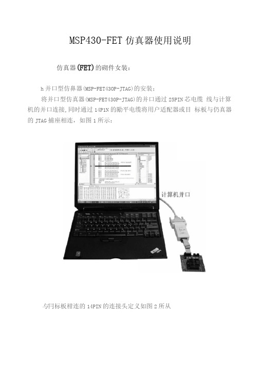
MSP430-FET仿真器使用说明仿真器(FET)的砌件女装:h并口型仿鼻器(MSP-FET43OP-JTAG)的安装;将并口型仿真器(MSP-FET430P-JTAG)的并口通过25PIN芯电缆线与计算机的并口连接,同时通过14P1N的勵平电缆将用户适配器或目标板与仍真器的JTAG捕座相连,如图1所示:与冃标板柑连的14PIN的连接头定义如图2所从注意:如果出现仿貞•器(FET )程序无法下载调试,请核对连接线 足否连接好,适配器上足否安装了芯片。
计算机并口应设为EPP 或 ECP 模式,若不符,请在CMOS 中修改。
2、USB 型MSP43O 仿真器(MSP-FET43【)U-JTAG )的安装: A :将MSP-FET430U-JTAG 的USB 调试接I 丨与USBHi 缆线连到PC 机 的USB 口。
B : WINDOWS 应找到 如 “ MSP-FET430UIF ・JTAG Idol ”的 新硬件,如图3所示:Q 发現新陵件xMSP-FET430UIF JTAG ToolC :硕件向导应会口动运行并弹出“找到新的硬件向导”的对话窗 II,然后选择相应选项继续“卜一步”,如削4所示:VCC_MSP NC XOUT TesWpp (ACLK) (ACLKEN) (TCLKEN)TDOfTDI TDkVpp TMS TCK GND RST/NMI NC图2欢迎使用找到新険件问导将逋刃在计賞机、W*S» CB « rindwi 显綸留站俺么尤许的苗况下廿舌际和兰前和更 4堀利iwshadew可皿權劲“Mr, VpitU “粉软啊"04.这一曲临次連疫设备rr⑴OW ■首吋不0>••击•下一步■ «».[下一古Op))「凰溥 ]D:选择“从列表或指定位置安装(高级)",如图5所示:E:然后指爪侦件向导驱动用序的位置(位于光盘屮USI3FET driver 11 录下),继续“下一步”,如图6所示F:硬件向导会提示找到合适的驱动程序,此时出现"没冇通过Windows®标测试”的警告信息•忽略警告倍息,选择“仍然继续” • 如图7所示:G:然后安装向导提示•安装定成,按“完成"确定,如图8所示:图8【;关闭安装向导Jn , WindowsH动识别另一个硬件"MSP-FET430UIF 串口,即为MSP-FET430U-JTAG'* ,如图9所示:图9J:找到新硕件后,硕件向导会再次启动,然后匝复以上步骤,直至安装完成。
- 1、下载文档前请自行甄别文档内容的完整性,平台不提供额外的编辑、内容补充、找答案等附加服务。
- 2、"仅部分预览"的文档,不可在线预览部分如存在完整性等问题,可反馈申请退款(可完整预览的文档不适用该条件!)。
- 3、如文档侵犯您的权益,请联系客服反馈,我们会尽快为您处理(人工客服工作时间:9:00-18:30)。
MSP430开发板使用说明书VER4.02012-02-02一、开发板简介 (1)1、开发板简介 (1)2、开发板总体资源 (1)3、开发板功能特点 (1)二、使用说明 (4)1、编程接口说明 (4)2、 LED显示 (5)3、数码管 (6)4、串口 (7)5、 AD输入和DA输出(PCF8591) (8)6、标准JTAG口 (10)7、 USB口 (11)8、 PS2键盘接口 (13)9、继电器、蜂鸣器和步进电机 (14)10、键盘 (14)11、 DS1302 (15)12、 LCD插座 (16)13、红外发射接收 (17)14、 FLASH芯片 (18)15、 EEPROM (18)一、 开发板简介1、开发板简介该实验开发板将单片机和各种外围资源集中在一起的一个很好的学习型开发板,包括了丰富的硬件资源,能够实现各种常用的功能,各个模块通过跳线与单片机相连,操作简单,并附带有各个模块的调试程序,供参考,以便于学习,通过使用该开发板可以提高使用者的学习兴趣,以便于深入的学习,该实验板整合了各种资源,是很好的学习工具。
2、开发板总体资源MSP430F2618(兼容LQFP64的引脚MSP430F148、MSP430F149、MSP430F156、MSP430F1698、MSP430F2410、MSP430F2418等)开发板上主要集成了USB模块、1602液晶接口、12864液晶接口、RS232接口、RS485接口、PS2接口、步进电机驱动模块、NRF2401和NRF905无线模块接口、ADC、DAC接口、EEPROM、Flash汉字库、实时时钟、温度传感器接口、蜂鸣器、继电器、红外发送器、红外接收器、数码管、4×4键盘、LED流水灯等电路,包括了几乎所有的常用接口和应用电路,适合有志于学习嵌入式系统设计和开发的广大朋友开发学习之用。
3、开发板功能特点1)USB接口,支持USB供电、USB通信(和PC机通信)、USB编程(BSL编程),无需额外的编程器,板子支持USB下载,一根USB线就可以实现程序的下载,使用简单、方便;2)74HC595驱动八个红、绿、黄相间的LED流水灯,可以做SPI接口实验,方便程序的调试;3)所有引脚由单排排针引出,2.54mm标准间距,扩展方便;4)滤波电路齐全,数字电源和模拟电源用0欧电阻隔离,数字地和模拟地也用0欧电阻隔离;5)板上留有标准14针JTAG仿真调试接口和复位按键;6)板上预留三路3.3V和5V的取电接口,方便为外围设备供电;7)板上配有四个铜柱,增强电路板的耐用性和可靠性。
8)两种可选供电方式(标准稳压器接口、USB接口);9)一个标准的RS232接口,可以通过跳线选择P3.4和P3.5或者P3.6和P3.7,实际上相当于两个串口都可以使用;10)一个标准的PC键盘接口(六芯PS/2接口);11)一个蜂鸣器;12)一个继电器 + 继电器接口端子+继电器驱动指示灯;13)一个12-Bit高精度温度传感器DS18B20接口;14)一个标准的1602液晶接口;15)两个标准的12864液晶接口(一个是最常用的标准20针接口,另一个新式12864液晶接口);支持5V和3V液晶模块;16)一路12-Bit模数转换器(ADC)接口,可以进行AD采集实验;17)六位共阳极动态扫描数码管;18)DS1302实时时钟;19)备用纽扣电池;20)EEPROM存储器AT24C64,不是AT24C02;EEPROM芯片增加了直插式接口,可以同时焊接贴片和直插式的EEPROM芯片,学习多个I2C 器件编程方法。
用直插式的EEPROM芯片,配合PC机软件可以作为编程器使用(如给彩电的EEPROM芯片刷写数据等);21)单路输出8位数模转换器(DAC),并包含4路8位AD输入;22)一个4×4的矩阵式键盘;23)一个4×1的独立式按键(与4×4的矩阵式键盘复用);24)两路串口通信指示灯;25)步进电机驱动芯片+步进电机接口;26)一个红外接收器;27)一个红外发射器;28)一个工业常用的RS485驱动芯片 +RS485接线端子;29)两个无线收发模块NRF2401和NRF905接口,可用来扩展无线通信模块;30)调节1602和12864的跳线选择,可以调节1602或者12864的显示对比度;31)提供电源指示灯和上电自动复位、手动复位电路。
32)可以插拔式的大容量FLASH存储器,可以当做一个编程器使用(FLASH是1M字节,可存储四种字体的国标汉字库,里面已经下载了四种国标汉字库,宋体、黑体、楷体和圆体),并支持自行设计多种字体的点阵库和图片库等;33)移植好的嵌入式操作系统uC/OS-II(已经移植到MSP430F2618的CPU上),可以帮助你快速入门嵌入式操作系统。
该uC/OS-II里面一共有8个任务,可同时测试DA、AD、按键、串口0、数码管、蜂鸣器、继电器、DS18B20模块和LED等模块。
MSP430F2618二、 使用说明1、编程接口说明使用USB接口下载程序的时候,把J26(J26和J27这两个排针是连接在一起了)BSL_R-TXD、BSL_T-RXD用跳线帽短接起来,再把J27的RTS-TCK、DTR-RST用跳线帽短接,参见下图所示,然后用USB线和PC机连接好,打开上位机编程软件,选择串口,并做相应设置,点击相应的按钮,即可进行相应的下载操作。
如图1所示。
注意,如果使用串口通信,要把J27的跳线帽全部取下,只把J26上的TXD-P3.5、RXD-P3.4用跳线帽短接,即可实现和PC机的串行通信。
如果使用并口或者USB仿真器调试程序,请把J27上的跳线帽全部断开。
图12、LED显示实验板上面共有8个LED灯,通过一片74HC595驱动,74HC595是具有8位移位寄存器和一个存储器,三态输出功能,有串入并出数据移位的作用。
使用的是MSP430F2618单片机的P2.4、P2.4、P2.4口来控制74HC595,如图2所示。
图2程序请参考光盘程序文件夹。
3、数码管实验板上一共设计了6个数码管,使用P4口和P5口驱动,使用的时候要把跳线J20短接,才能使数码管工作。
P4口是段选,P5是位选,如图3-4所示。
图 3图4程序请参考光盘程序文件夹。
4、 串口一个标准的MAX3232串行接口,可以通过跳线选择P3.4和P3.5或者P3.6和P3.7,实际上相当于两个串口都可以使用。
使用串口通信的时候,请按照图4进行跳线。
如果使用P3.4和P3.5(即串口0),则应该把J24的5-7、6-8短接;如果使用P3.6和P3.7(即串口1),则应该把J24的3-5、4-6短接;如果使用MAX485通信,则应该把J24的1-3、2-4短接,此时,MAX485芯片使用的是P3.6和P3.7(即串口1)。
D1和D2是串口通信指示灯,连接在P3.4和P3.5。
如图5-6所示。
J20图 5图6程序请参考光盘程序文件夹。
5、 AD 输入和DA 输出(PCF8591)AD 输入是用的是MSP430F2618单片机片内自带的12精度的AD 转换器,使用的是P6.7引脚,把J30的1-2脚短接,即可通过调节R_AD1电位器调节输入模拟电压的大小。
DA 输出采用的是PCF8591芯片。
PCF8591是具有I2C 总线接口的8位A/D J24及 D/A 转换器,有 4 路 A/D 转换输入,1 路 D/A 模拟输出。
I2C 总线系统与传 统的并行总线系统相比具有结构简单、可维护性好、易实现系统扩展、易实现 模块化标准化设计、可靠性高等优点。
模拟信号从跳线 J30 的 3 脚输出,在使用的时候,可以用万用表测量 J30 的第 3 脚和地之间的电压数值,也可以把 J30 的 3-4 用跳线短接,则 DAC 的输 出直接驱动 DAC_LED, 可以通过 DAC_LED 亮度的变化直观地观察到 DAC 输 出电压值的变化。
也可以把模拟输出信号送入到 MSP430F2618 单片机的 AD 进行转换, 即把 J30 的 2-3 用跳线帽短接。
也可以通过 J29 的 1、 3、 给 PCF8591 2、 4 输入模拟信号,使用 PCF8591 进行 AD 转换实验。
如图 7-8 所示。
图79PCF8591J30图8 程序请参考光盘程序文件夹。
6、 标准 JTAG 口JTAG 接口采用的是 TI 标准的 14 引脚接口, 可以通过跳线 J12 来选择给实 验板供电,还是通过实验板给外部仿真器供电,如果把 J12 的 1-2 用跳线短接, 则可以通过仿真器给实验板供电(注意,这个功能需要仿真器的支持,即仿真 器有给实验板供电的功能) ;如果把 J12 的 2-3 用跳线短接,则可以通过实验板 给仿真器供电。
如图 9-10 所示。
10图9J12 标准 14 针 JTAG 接口图107、 USB 口该实验板可以通过 USB 接口给实验板供电、USB 通信(和 PC 机通信) 、 USB 下载程序(BSL 编程) 。
使用该 USB 接口,无需额外的编程器,就可以给 实验板下载程序,一根 USB 线就可以实现程序的下载,使用简单、方便。
如图 11-12 所示。
其中,K1 是电源开关,按下 K1 则使用 USB 给实验板供电,松开开关 K1,11则使用外部电源给实验板供电(即通过 J21 外部电源供电) ,外部电源要求使用 直流电源,电压最好在 6V~10V 的范围之间。
D5 是防止外部电源插反二极管, 可以保护实验板。
U1 是 USB 转串口芯片,在使用 USB 下载或者通信之前应该先安装 USB 驱动程序,驱动程序见光盘资料中的“USB 驱动.rar”。
图1112USB 芯片图12 程序请参考光盘程序文件夹。
8、 PS2 键盘接口PS2 端口使用了标准的六芯插座,可以接收来自标准键盘、鼠标的数据。
单片机接收键盘发送过来的时钟信号和数据信号,然后对数据信号进行解码。
如图 13 所示。
图1313程序请参考光盘程序文件夹。
9、 继电器、蜂鸣器和步进电机继电器是通过 P6.2 来驱动的,蜂鸣器是通过 P6.1 来驱动的,步进电机是 通过 P3.0、P3.1、P3.2、P3.3 来驱动的。
值得注意的是 UL2003 驱动器里面有 反相器,比如说要想让蜂鸣器叫,则应该给 P6.1 口送高电平(即 1) 。
如图 14 所示。
图14 程序请参考光盘程序文件夹。
10、 键盘按键接在 P1 口,按键采用的是 4×4 矩阵式键盘和 4×1 独立式按键复用的 方式,P1.0~P1.3 接有上拉电阻,作为输入端口,P4.0~P1.7 没有上拉电阻,作 为输出端口。
