MMDT2227M-7中文资料
QZTT2227-2017基站用梯级磷酸铁锂电池集成技术要求
中国铁塔股份有限公司企业标准Q/ZTT 2227-2017基站用梯级磷酸铁锂电池集成技术要求Technical requirements of enchelon use liFePO4 battery systemfor base station版本号:V1.02017 - 12 - 04发布2017 - 12 - 05实施中国铁塔股份有限公司发布目次前言 (III)1 范围 (1)2 规范性引用文件 (1)3 术语和定义 (2)4 产品规格 (4)4.1单体电池数量 (4)4.2电池组输出电压标称值 (4)5 要求 (4)5.1使用环境条件 (4)5.2外观、标识及安装 (5)5.3性能指标 (6)5.4寿命 (9)5.5安全性能 (10)6 BMS要求 (13)6.1基本要求 (13)6.2信息采集要求 (14)6.3信息测量显示精度 (14)6.4BMS管理功能 (15)6.5监控通讯 (18)6.6电磁兼容性 (19)7 出厂检验 (20)附录 A BMS外部通信协议 (23)A.1物理接口和通信方式 (23)A.2协议的基本格式 (23)A.3数据格式 (26)A.4编码分配 (29)A.5磷酸铁锂电池BMS通信协议 (30)附录B (55)前言梯级利用磷酸铁锂电池是指车用动力电池在容量衰减到80%以下后,用于通信基站备电、储能等场景的电池。
随着锂电池成本的不断下降,这种能量密度更高、寿命更长的电池正变得更具竞争力,部分场景取代铅酸蓄电池成为可能,梯级利用电池有望进一步降低基站建设成本,并在削峰填谷、太阳能基站等场景发挥优势,创造价值。
梯级电池在循环寿命、能量密度、高温性能等方面的性能指标均优于铅酸蓄电池,在技术上可满足现网各种工况的备电需求,不同循环寿命梯级电池适用于不同应用场景;经济上也可行,较铅酸蓄电池价格便宜,可节省大量建设资金。
依据目前梯级电池的综合情况,为指导公司对电动汽车退役电池电芯集成成组后电池的采购、使用和维护特制定本技术要求。
MMDT2227-7-F中文资料

Delay Time
td
¾
Rise Time
tr
¾
Storage Time
ts
¾
Fall Time
tf
¾
Note: 3. Pulse test: Pulse width £ 300ms, duty cycle £ 2%.
@ TA = 25°C unless otherwise specified
Max
10
nA
VEB = 3.0V, IC = 0
20
nA
VCE = 60V, VEB(OFF) = 3.0V
¾
IC = 100mA, VCE = 10V
¾
IC = 1.0mA, VCE = 10V
¾
IC = 10mA, VCE = 10V
300
¾
IC = 150mA, VCE = 10V
¾
IC = 500mA, VCE = 10V
Symbol VCBO VCEO VEBO IC
PNP2907A -60 -60 -5.0 -600
Note:
1. Device mounted on FR-4 PCB, 1 inch x 0.85 inch x 0.062 inch; pad layout as shown on Diodes Inc. suggested pad layout document AP02001, which can be found on our website at /datasheets/ap02001.pdf.
35
30
f = 1MHz
25
20
15
Cibo
10
5
Cobo
布斯曼系列ATM插线保护器数据表说明书

ATM blade fusesCatalog symbol•ATM-_DescriptionA range of UL ® Listed fast-acting miniature blade fuses for automotive and low-voltage circuits.Ratings• Volts: 32 Vac/dc • Amps: 2 to 30 A •Interrupting rating: 1 kAAgency information• UL Listed, Guide FHXT , File AU169•ISO 8820-3 / JASO D612 / SAE J2077 and J1171 ignition protectionMaterials• Silver-plated zinc terminals and element •Polyamide housing with UL 94 HB flammabilityratingEnvironmental•Operating temperature range -40°C to +80°C, 95% RH non-condensing•Storage temperature range -5°C to +35°C or lower, 85% RH non-condensingBasic catalog numbersATM-2Gray ATM-15Blue ATM-3Violet ATM-20Y ellow ATM-4Pink ATM-25Clear ATM-5Tan ATM-30GreenATM-7-1/2Brown* Available only in traditional and bulk pack.Packaging codesReload ATM-(amp)RLD*10 fuses in a polybag Retail pack BP/ATM-(amp)-RP 5 fuses in a blister card Value pack VP/ATM-(amp)-RP 25 fuses in a clamshell packBulk packBK/ATM-(amp)500 fuses in a carton* Not available for the 4 amp ATM fuses.Dimensions — inOperating @ 23°C*135%0.75 sec 600 sec 160%0.25 sec 50.0 sec 200%0.15 sec 5.0 sec 350%0.04 sec 0.5 sec 600%0.02 sec0.1 sec* Fuse characteristics may vary according to the conditions under which they are used. Fuse derating with change in ambient temperature: -0.15% / 1°C.Features• Halogen free and RoHS compliant •Test points on fuse housing speeds troubleshooting•Industry standard color coded by amp ratingT ypical applications• Automotive•Low voltage control circuitsRecommended fuse holders, add-a-circuit and fuseclipsHHH additional fused circuit on a block 32V/10A 5”/#16HHLInline fuse holder with cover 32V/20A 2x4”/#16HHM Inline fuse holder with cover 32V/30A 2x4”/#12HHU Water resistant inline fuse holder with cover32V/30A 2x4”/#12ATM-FHIDIndicating inline fuse holder with cover 32V/20A 2x4”/#161A5778**PCB fuse clip 32V/15A —1A5779**PCB fuse clip with nylon base32V/15A—** See data sheet no. 2131 for details.HALOGENHF FREEATM blade fusesTechnical Data 2048Effective January 2019Eaton and Bussmann are valuable trademarks of Eaton in the US and other countries. Y ou are not permitted to use the Eaton trademarks without prior written consent of Eaton.Eaton1000 Eaton Boulevard Cleveland, OH Bussmann Division 114 Old State Road Ellisville, MO 63021United States/bussmannseries© 2019 EatonAll Rights Reserved Printed in USAPublication No. 2048 — BU-SB15054January 2019Follow us on social media to get thelatest product and support information.For Eaton’s Bussmann series product information,call 1-855-287-7626 or visit:/bussmannseriesThe only controlled copy of this data sheet is the electronic read-only version located on the Eaton network drive. All other copies of this document are by definition uncontrolled. This bulletin is intended to clearly present comprehensive product data and provide technical information that will help the end user with design applications. Eaton reserves the right, without notice, to change design or construction of any products and to discontinue or limit distribution of any products. Eaton also reserves the right to change or update, without notice, any technical information contained in this bulletin. Once a product has been selected, it should be tested by the user in all possible applications.Time-current characteristic curves — average meltT i m e i n s e c o n d sCurrent in amps1 A15 A10 A7-1/2 A5 A 4 A 3 A 2 A20 A 25 A30 A 1109876543210010000.010.1110,000100010010Electrical characteristics249.7 m Ω140 mV 329.6 m Ω140 mV 423.8 m Ω136 mV 5 A 16.7 m Ω112 mV 7-1/211.1 m Ω112 mV 107.82 m Ω106 mV 15 4.93 m Ω99 mV 20 3.48 m Ω95 mV 25 2.58 m Ω92 mV 302.12 m Ω86 mV。
MMDT3946中文资料
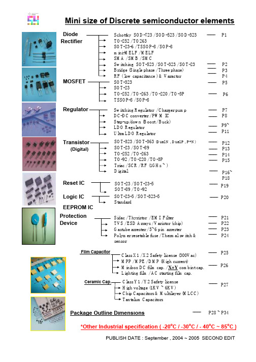
N+P
N+P
SOT-23 (P.28)
BC807 BC817 BC846 BC847 BC848 BC856 BC857 BC858 BCW65C MMBT1015 MMBT1815 MMBT2222A MMBT2369 MMBT2484 MMBT2907A MMBT3904 MMBT3906 MMBT4124 MMBT4125 MMBT4401 MMBT4403 MMBT5086 MMBT5087 MMBT5088 MMBT5089 MMBT5401 MMBT5550 MMBT5551 MMBT6427 MMBT6429 MMBT6517 MMBT6520 MMBT8050 MMBT8099 MMBT8550 MMBT8599 MMBT9018 MMBTA06 MMBTA13 MMBTA14
Ceramic Ckage Outline Dimensions
P28 ~ P34
o o
*Other Industrial specification ( -20 C / -30 C / - 40 C ~ 85 C )
PUBLISH DATE : September , 2004 ~ 2005 SECOND EDIT
BCE BCE BCE BCE BCE BCE BCE BCE DAUL DAUL DAUL DAUL DAUL DAUL DAUL DAUL
N+P
SOT-363 (P.29)
MMDT2412 MMDT3904 MMDT2222 MMDT2411 MMDT1036 MMDT1037 MMDT3906 MMDT2907 MMDT2227 MMDT3946
PNP NPN NPN NPN NPN PNP PNP PNP NPN PNP NPN NPN NPN NPN PNP NPN PNP NPN PNP NPN PNP PNP PNP NPN NPN PNP NPN NPN NPN NPN NPN PNP NPN NPN PNP PNP NPN NPN NPN NPN -50 50 80 50 30 -80 -50 -30 60 -50 60 75 40 60 -60 60 -40 30 -30 60 -40 -50 -50 35 30 -160 160 180 40 55 350 -350 25 80 -25 -80 20 80 30 30 -45 45 65 45 30 -65 -45 -30 32 -50 50 40 40 60 -60 40 -40 25 -30 40 -40 -50 -50 30 25 -150 140 160 40 45 350 -350 20 80 -20 -80 15 80 30 30 -800 800 100 100 100 -100 -100 -100 800 -150 150 600 500 50 -600 200 -200 200 -200 600 -600 -50 -50 50 50 -600 600 600 500 200 500 -500 700 500 -700 -500 50 500 300 300 225 225 225 225 225 225 225 225 225 225 225 225 225 225 225 225 225 225 225 225 225 225 225 225 225 225 225 225 225 225 225 225 225 225 225 225 225 225 225 225 100 100 110 110 110 115 110 110 250 120 120 100 40 250 100 100 120 120 50 100 100 150 250 300 400 60 60 80 20K 500 30 30 150 100 150 100 30 50 10K 20K 630 630 800 800 800 800 800 800 630 700 700 300 120 300 300 360 360 150 300 300 500 800 900 1200 240 250 250 200K 1250 200 200 500 300 400 300 400 -100 100 2 2 2 -2 -2 -2 100 -2 2 150 10 1 -150 10 -10 2 -2 150 -150 -0.1 -0.1 0.1 0.1 -10 10 10 100 0.1 30 -30 150 1 -150 -1 1 10 100 100 -1 1 5 5 5 -5 -5 -5 1 -6 6 10 1 5 -10 1 -1 1 -1 1 -2 -5 -5 5 5 -5 5 5 5 5 10 -10 1 5 -1 -5 6 1 5 5 -0.7 0.7 0.25 0.25 0.25 -0.3 -0.3 -0.3 0.3 -0.3 0.25 0.5 0.25 0.35 -0.4 0.2 0.25 0.3 -0.4 0.4 -0.4 -0.3 -0.3 0.5 0.5 -0.2 0.25 0.15 1.2 0.2 0.5 -0.5 0.5 0.4 -0.5 -0.4 0.5 0.25 1.5 1.5 -500 500 10 10 10 -10 -10 -10 100 -100 100 380 10 1 -150 10 -10 50 -50 150 -150 -10 -10 10 10 -10 50 10 50 10 30 -30 500 100 -500 -100 5 100 100 100 -50 50 0.5 0.5 0.5 -0.5 -0.5 -0.5 10 -10 10 10 1 0.1 -15 1 -1 5 -5 15 -15 -1 -1 1 1 -1 5 1 0.5 0.5 3 -3 50 5 -50 -5 0.5 10 0.1 0.1 100 40 40 150 150 150 150 500 100 125 125 200 300 250 300 200 250 200 40 40 50 50 100 100 100 100 100 300 300 300 150 150 150 170 80 80 300 500
T-BERD 2207用户指南说明书

198150-15217-01Rev. DT-BERD 2207USER’S GUIDEThis manual applies to all T-BERD 2207 software incorporating software level 3.x.JANUARY 2000Copyright ©1998 TTC®USA 1-800-638-2049 • +1-301-353-1550 • FAX +1-301-353-0234Canada 1-888-689-2165 • +1-905-507-4117 • FAX +1-905-507-4126SECTION 9 - SpecificationsGeneral SpecificationsSECTION 9 SPECIFICATIONS9.1GENERAL SPECIFICATIONS9.1.1Physical Characteristics:Height:7.5" (19 cm)Width:11.5" (29.2 cm)Depth: 2.25" (5.7 cm)Weight: 4.25 lb. (1.93 kg.)9.1.2Environmental Characteristics:Temperature:Operating:32°F to 122°F (0°C to +50°C)Non-Operating:-40°F to 167°F (-40°C to +75°C)Humidity:10% to 90% Relative Humidity, non-condensing9.1.3Electrical Characteristics:Battery Type:10.8 V Nickel-Metal Hydride (NiMH)Operating Time:Typically, up to three hours of continuous operation on a full chargeRecharging Period:Maximum of two hours from full dischargeAC Adaptor:120VAC to 18 VDC 1.2A9.2DS1 SPECIFICATIONS9.2.1Input Specifications9.2.1.1RX JackConnector Type:Bantam jackFrequency:1,544,000 Hz ±5000 HzUser’s Guide T-BERD 22079-1SECTION 9 - SpecificationsDS1 SpecificationsImpedanceBRIDGE:1000 ohms minimumTERM:100 ohms ±5%DSX-MON:100 ohms ±5%RangeBRIDGE:+6 to -35.0 dBdsxTERM:+6 to -35.0 dBdsxDSX-MON:+6 to -24.0 dBdsx of resistive los9.2.1.2Loop Codes Detection CriteriaIn-Band:At least 177 error-free bits of the selected repetitive pattern must be received(loop up or loop down).Out-of-Band:Datalink monitored every 125 ms for loop codes (loop up and loop down).9.2.1.3Pattern Synchronization Detection CriteriaFixed Patterns:30 consecutive error-free bitsPseudo-random:30 + n consecutive error-free bits for a pattern length of 2^n-19.2.2Output Specifications9.2.2.1TX JackConnector Type:Bantam jackLBO Level:Line build-out of 0, -7.5, -15.0, and -22.5 dB of cable loss at 772 HzLBO Tolerance:±2 dB at 772 kHzTiming:±7 ppm internal or recoveredLine Codes:AMI or B8ZSError Insert Type:Logic, BP V, or FramePulse Shape:With output terminated in 100 ohms resistive load and 0 dB line build-outselected, the T-BERD 2207 meets ITU-T Recommendation G.703; AT&TPublications CB113, CB119, CB132, CB143, and PUB62508; and AT&TPUB62411 pulse shape specifications.9-2T-BERD 2207User’s GuideSECTION 9 - SpecificationsDS1 Specifications 9.2.2.2Transmitted Loop CodesIn-BandCSU:Loop-up: 10000; Loop-down: 100Facility 1:Loop-up: 1100; Loop-down: 1110Facility 2:Loop-up: 11000; Loop-down: 11100Facility 3:Loop-up: 100000; Loop-down: 100Out-of-BandLine:Loop up: 1111 1111 0111 0000Loop down: 1111 1111 0001 1100Payload:Loop up: 1111 1111 0010 1000Loop down: 1111 1111 0100 1100Network:Loop up: 1111 1111 0100 1000Loop down: 1111 1111 0010 01009.2.3Measurement SpecificationsFrequencyRange:1,544,000 ±5000 HzAccuracy:± 7 ppmResolution: 1 HzReceived LevelRange:+6 dBdsx to -40 dBdsxAccuracy:±1.0 dB between +6 and -10 dBdsx±2.0 dB between -10 and -20 dBdsx±3.0 dB between -20 and -40 dBdsxResolution:0.1 dBVp-p Range:60 mV to 12.0 VVp-p Resolution:0.05 VSimplex CurrentRange:10 mA to 180 mAccuracy:±5%Resolution: 1 mASimplex path:13.2 ohms (nominal)User’s Guide T-BERD 22079-3SECTION 9 - SpecificationsDS1 Specifications9.2.4Alarm CriteriaSignal Loss:175 ±75 consecutive zerosFrame LossD4: 2 out of 5 Ft bits in errorESF: 2 out of 5 frame bits in errorSLC-96: 2 out of 5 Ft bits in errorPattern Loss:100 errors detected in 1000 or fewer bitsOnes DensityQRSS:Alarm is suppressed.Other Patterns:Received data contains less than n ones in 8(n+1) bits, where n=1 to 23.Excess ZeroAMI:16 or more consecutive zerosB8ZS:8 or more consecutive zerosYellow AlarmD4:Bit 2 is a 0 for 255 consecutive channels.ESF:256 bits ±16 bits of a repetitive (1111 1111 0000 0000) pattern received inthe 4 kb/s datalink.SLC-96:Bit 2 is a 0 for 255 consecutive channels.AIS:Unframed T1 signal has 2048 consecutive ones.Low Battery:Battery has less than 25% energy remaining.9-4T-BERD 2207User’s GuideSECTION 9 - Specifications DS3 Option SpecificationsUser’s Guide T-BERD 22079-59.3DS3 OPTION SPECIFICATIONS9.3.1DS3 Specifications9.3.1.1Framing Formats9.3.1.2Patterns9.3.1.3Line Coding•B3ZS9.3.1.4Connectors•WECO 560A jack9.3.1.5Receiver (Single)Frequency:44,736 Mb/s ±300ppmLevel:HIGH: Accepts Nominal 1.2 Vp, 0 ft. of cable from High sourceDSX: Accepts Nominal 0.6 Vp, 450 ft. of c able from High source or monitor LOW: Accepts Nominal 0.3 Vp, 900 ft. of cable from High source9.3.1.6Transmitter (Single)Frequency:44,736 Mb/s ±20ppmPulse:HIGH: Nominal 1.2 Vp (Signal meets ANSI specification T1.102-1993 and ITU-TG.703 when subjected to 450 feet of cable loss.)•Auto• Muxed M13•Unframed • C-bit•M13• Muxed C-bit•1111• 215-1•1100 (Idle)• 220-1•1010 (AIS)• 223-1•1010• User (3 to 24 bit programmable)SECTION 9 - SpecificationsDS3 Option SpecificationsDSX: Nominal 0.91 Vp (Signal meets ANSI specification T1.102-1993 andITU-TG.703.)LOW: Nominal 0.31 VpTiming:Internal ClockRecovered Clock9.3.2DS3 Measurements9.3.2.1Summary•Bit Errors•Frame Errors•Bipolar Violations•Receive Frequenc•Parity Errors•FEAC Messages•C-bit Errors•DS2 Frame Errors•FEBE•Pattern Slip9.3.2.2Logic•Bit Errors•Pattern Slips•Bit Error Rate•Pattern Loss Seconds•Bit Errored Seconds•Error Free Seconds•Pattern Losses•% Error Free Seconds9.3.2.3Bipolar Violations•BPV•BPV Rate•BPV Errored Seconds9-6T-BERD 2207User’s GuideSECTION 9 - SpecificationsDS3 Option Specifications 9.3.2.4Frame Errors•Frame Error Rate•FEBE Rate•Frame Error Seconds•DS2 Frame Errors•Out of Frame Seconds•DS2 Frame Error Rate•C-bit Errors•Received X-bit•C-bit Error Rate•Transmit X-bit•FEBE•Frame Loss Count9.3.2.5Parity•Parity Errors•Parity Error Rate•Parity Error Seconds9.3.2.6Signal•Signal Loss•Signal Loss Seconds•Receive Frequency•Receive Signal Level•Transmit FrequencyUser’s Guide T-BERD 22079-7。
光宝科技 MaxTester 730C PON metro OTDR 规格手册说明书
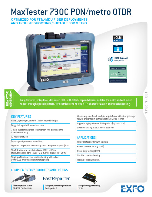
S P E C S H E E TN E W O T D R G E N E R A T I O NKEY FEATURESHandy, lightweight, powerful, tablet-inspired design Rugged design built for outside plant7-inch, outdoor-enhanced touchscreen–the biggest in the handheld industry 12-hour battery lifeTamper-proof password protectionDynamic range up to 39 dB for up to 132 km point-to-point (P2P)Short dead zones: event dead zone (EDZ) = 0.5 m;attenuation dead zone (ADZ) = 2.5 m; PON dead zone = 30 m Single port for in-service troubleshooting with in-line 1490/1550 nm PON power meter (optional)iOLM-ready: one-touch multiple acquisitions, with clear go/no-go results presented in a straightforward visual format Supports high port count PON splitters (up to 1x128)Live fiber testing at 1625 nm or 1650 nmAPPLICATIONSFTTx/PON testing through splitters Access network testing (P2P)Metro links testing (P2P)Live fiber troubleshooting Passive optical LAN (POL)MaxTester 730C PON/metro OTDRFully featured, entry-level, dedicated OTDR with tablet-inspired design, suitable for metro and optimized to test through optical splitters, for seamless end-to-end FTTH characterization and troubleshooting.OPTIMIZED FOR FTTx/MDU FIBER DEPLOYMENTS AND TROUBLESHOOTING, SUITABLE FOR METROCOMPLEMENTARY PRODUCTS AND OPTIONSFiber inspection scope FIP-400B (WiFi or USB)Data post-processing software FastReporter 3Soft pulse suppressor bag SPSBTHE HANDHELD OTDR. . . REINVENTED.The MaxTester 700B/C Series is the first tablet-inspired OTDR line that is handy, lightweight and rugged enough for any outside plant environment. With a 7-inch, outdoor-enhanced touchscreen–the most efficient handheld display in the industry–it delivers an unprecedented user experience. Its intuitive Windows-like GUI ensures a fast learning curve. Plus, its new and improved OTDR 2 environment offers icon-based functions, instant boot-up, automatic macrobend finders as well as improved auto and real-time modes.The MaxTester 700B/C Series is a line of genuine high-performance OTDRs from the world’s leading manufacturer. It delivers EXFO’s tried and true OTDR quality and accuracy along with the best optical performance for right-first-time results, every time. The amazing 12-hour battery life will never let a technician down, and the plug-and-play hardware options, like the VFL, power meter and USB tools, make every technician’s job easier.Most importantly, the MaxTester 700B/C Series is finally bringing the intelligent Optical Link Mapper (iOLM), an intelligent OTDR-based application, to the handheld market. This advanced software turns even the most complex trace analysis into a simple, one-touch task.Ultimately, the MaxTester 700B/C Series is small enough to fit in your hand and big enough to fit all your needs!THE ENTRY-LEVEL SOLUTION DESIGNED FOR ALL YOUR TESTING NEEDSThe MaxTester 730C PON/metro OTDR is optimized to test through optical splitters up to 1x128, ensuring complete end-to-end FTTH characterization. The 1625-nm or 1650-nm, out-of-band, live testing port enables the efficient troubleshooting of active networks without affecting the signal of other clients. Plus, the high dynamic range makes it suitable for metro P2P testing. Other models available:•MaxTester 715B short access and FTTx last-mile installation and troubleshooting•MaxTester 720C LAN/WAN access OTDR—optimized for multimode and singlemode access network construction and troubleshooting SECURE YOUR INVESTMENT AGAINST THEFTProtected instruments have no value on the black market making them completely unappealing to thieves.With our security management option, administrators can define and load a tamper-proof security profileon the MaxTester, displaying a property message on the home screen and securing it with a user password(permanent or renewable).LOOKING FOR ICON-BASED MAPPING?Linear view (included on all EXFO OTDRs)Available on our OTDRs since 2006, the linear view simplifies the reading of an OTDR trace by displaying icons in a linear way for each wavelength. This view converts the graph data points obtained from a traditional single pulse trace into reflective, non-reflective or splitter icons. With applied pass/fail thresholds, it becomes easier to pinpoint faults on your link.This improved linear view offers you the flexibility to display both theOTDR graph and its linear view without having to perform a toggleto analyze your fiber link.Although this linear view simplifies OTDR interpretation of a singlepulse-width trace, the user must still set the OTDR parameters.In addition, multiple traces must often be performed in order tofully characterize the fiber links. See the section below to learnabout how the iOLM can perform this automatically and with moreaccurate results.OTDR testing comes withits load of challenges...In response to these challenges, EXFO developed a better way to test fiber optics:application designed to simplify OTDR testing by eliminating the need to configure parameters, and/or analyze and interpret multiple complex OTDR traces. Its advanced algorithms dynamically define the testing parameters, as well as the number of acquisitions that best fit the network under test. By correlating multipulse widths on multiple wavelengths, the iOLM locates and identifiesIn addition to the standard iOLM feature set, you can select added-value features as part of the Order a unit with the iOLM application onlyCOMBORun both iOLM and OTDR applications (Oi code)Add the iOLM software option to your iOLM-ready unit, even while in the fieldGET THE BEST OUT OF YOUR DATA POST-PROCESSING— ONE SOFTWARE DOES IT ALLThis powerful reporting software is the perfect complement to your OTDR, and can be used to create and customize reports to fully address your needs.OPTICAL PLUG-AND-PLAY OPTIONSThe MaxTester features plug-and-play optical options that can be purchased whenever you need them: at the time of your order or later on. In either case, installation is a snap, and can be performed by the user without the need for any software update. Optical power meterEXFO’s high-level power meter (GeX) can measure up to 27 dBm, the highest in the industry. This is essential for hybrid fiber-coaxial (HFC) networks or high-power signals. If used with an auto-lambda/auto-switching compatible light source, the power meter automatically synchronizes on the same wavelength, thus avoiding any risk of mismatched measurement.•Extensive range of connectors•Auto-lambda and auto-switching•Offers measurement storage and reporting•Seven standard calibrated wavelengthsVisual fault locator (VFL)The plug-and-play VFL easily identifies breaks, bends, faulty connectors and splices, in addition to other causes of signal loss. This basic, yet essential troubleshooting tool should be part of every field technician’s toolbox. The VFL visually locates and detects faults over distances of up to 5 km by creating a bright-red glow at the exact location of the fault on singlemode or multimode fibers (available with the optical power meter only).FIBER CONNECTOR INSPECTION AND CERTIFICATION–THE ESSENTIAL FIRST STEP BEFORE ANY OTDR TESTING Taking the time to properly inspect a fiber-optic connector using an EXFO fiber inspection scope can prevent a host of issues from arising further down the line, thus saving you time, money and trouble. Moreover, using a fully automated solution with autofocus capabilities will turn this critical inspection phase into a fast and hassle-free one-step process.Did you know that the connector of your OTDR/iOLM is also critical?The presence of a dirty connector at an OTDR port or launch cable can negatively impact your test results, and even cause permanent damage during mating. Therefore, it is critical to regularly inspect these connectors to ensure that they are free of any contamination. Making inspection the first step of your OTDR best practices willmaximize the performances of your OTDR and your efficiency.PACKAGED FOR EFFICIENCY1Singlemode OTDR port610/100 Mbit/s Ethernet port11 2Singlemode Live OTDR port7Two USB 2.0 ports12 3Stylus8AC adapter13 4Power meter9Home/switch application andscreen capture (hold)5Visual fault locator10Power on/off/stand by123456789101113SOFTWARE UTILITIESSoftware update Ensure that your MaxTester is up-to-date with the latest software.VNC configuration The Virtual Network Computing (VNC) utility allows technicians to easily remote control the unit via a computer or laptop. Microsoft Internet Explorer Access the Web directly from your device interface.Data mover Transfer all your daily test results quickly and easily.Centralized documentation Instant access to user guides and other relevant documents.Wallpapers Enhance your work environment with colorful and scenic backgrounds.PDF Reader View your reports in PDF format.Bluetooth file sharing Share files between your MaxTester and any Bluetooth-enabled device.WiFi connection WiFi FIP inspection scope interface. Upload test results and browse the Internet.Inspection scope USB or WiFi scope to inspect and analyze connectors.FTP server Exchange files over WiFi to an FTP application on a smartphone for easier file sharing from the field.Security management Tamper-proof security profile with user password (permanent or renewable) and custom property message.SPECIFICATIONS a。
L7N使用手册中文
v
安全使用注意事项
接线注意事项
注意
▪ 伺服驱动器输入电源请使用 AC200-230[V]。 ▪ 确保伺服驱动器接地。 ▪ 请勿将常用电源直接,W 输出端。 ▪ 伺服驱动器的 U、V、W 输出端和伺服电机的电源输入端 U、V、W 直接接线,请勿在配线中间
1.2.1 伺服电机各部分名称............................................................................................................................ 1-3 1.2.2 伺服驱动器各部分名称 ........................................................................................................................ 1-4 1.3 连接器整体接线图............................................................................................................................................1-7
防止火灾注意事项
注意 ▪ 伺服驱动器、伺服电机、再生电阻请安装在阻燃物上。 ▪ 伺服驱动器发生故障时,请关闭电源。
iv
安全使用注意事项
安装注意事项
请在下列环境条件中保管及使用本产品。
环境 使用温度 保存温度 使用湿度 保存湿度
标高
安装间隔
其他
条件
伺服驱动器
伺服电机
0 ~ 50 ℃
OPA2227_datasheet

APPLICATIONS
q q q q q q q DATA ACQUISITION TELECOM EQUIPMENT GEOPHYSICAL ANALYSIS VIBRATION ANALYSIS SPECTRAL ANALYSIS PROFESSIONAL AUDIO EQUIPMENT ACTIVE FILTERS
±0.1
0.2 0.2 110
±0.5
±100 ±0.6
±0.3
T T T T
±200 ±2
T T
dc f = 1kHz, RL = 5kΩ
IB IOS
±2.5 ±2.5
±10 ±10
±10 ±10
T T
T T T T
90 15 3.5 3 3 0.4 (V+)–2 138 T T T
T T T T T T
High Precision, Low Noise OPERATIONAL AMPLIFIERS
FEATURES
q LOW NOISE: 3nV/√Hz q WIDE BANDWIDTH: OPA227: 8MHz, 2.3V/µs OPA228: 33MHz, 10V/µs q SETTLING TIME: 5µs (significant improvement over OP-27) q q q q q q HIGH CMRR: 138dB HIGH OPEN-LOOP GAIN: 160dB LOW INPUT BIAS CURRENT: 10nA max LOW OFFSET VOLTAGE: 75µV max WIDE SUPPLY RANGE: ±2.5V to ±18V OPA227 REPLACES OP-27, LT1007, MAX427
MMDT2227M-7;中文规格书,Datasheet资料

Lead-free GreenMMDT2227MCOMPLEMENTARY NPN / PNP SMALL SIGNAL SURFACE MOUNT TRANSISTOR·Complementary Pair·Epitaxial Planar Die Construction ·One 2222A Type (NPN), One 2907A Type (PNP)·Ideal for Low Power Amplification and Switching ·Lead Free By Design/RoHS Compliant (Note 2)·"Green Device" (Note 3)FeaturesMaximum Ratings, 2222A Type (NPN)@ T A = 25°C unless otherwise specifiedMechanical Data·Case: SOT-26·Case Material: Molded Plastic, “Green” MoldingCompound. UL Flammability Classification Rating 94V-0·Moisture Sensitivity: Level 1 per J-STD-020C ·Terminals: Finish - Matte Tin annealed over Copper leadframe. Solderable per MIL-STD-202, Method 208·Terminal Connections: See Diagram·Ordering & Date Code Information: See Page 3·Marking (See Page 3): K27·Weight: 0.006 grams (approximate)Note: 1. Device mounted on FR-4 PCB, 1 inch x 0.85 inch x 0.062 inch; pad layout as shown on Diodes Inc. suggested pad layout document AP02001, which can be found on our website at /datasheets/ap02001.pdf. 2. No purposefully added lead.3. Diodes Inc.'s "Green" policy can be found on our website at /products/lead_free/index.php.Maximum Ratings, 2907A Type (PNP)@ T A = 25°C unless otherwise specifiedNote: E1, B1, and C1 = 2907A Type (PNP), E2, B2, and C2 = 2222A Type (NPN).Type marking indicates orientation.Maximum Ratings, Total@ T A = 25°C unless otherwise specifiedElectrical Characteristics, 2222A Type (NPN)@ T A = 25°C unless otherwise specifiedNote: 4.Pulse test: Pulse width £ 300m s, duty cycle £ 2%.Note: 6. For Packaging Details, go to our website at /datasheets/ap02007.pdf.Electrical Characteristics, 2907A Type (PNP)@ T A = 25°C unless otherwise specified Note:5. Short duration pulse test used to minimize self-heating effect.Date Code KeyK27 = Product Type Marking Code YM = Date Code Marking Y = Year ex: S = 2005M = Month ex: 9 = SeptemberMarking InformationOrdering Information(Note 6)1.0100.1101.050C A P A C I T A N C E (p F )V , REVERSE VOLTS (V)R Fig. 1 (2222A) Typical CapacitanceCobo100Cibo0.0010.011100.11000.20.40.60.81.01.21.41.61.82.0I BASE CURRENT (mA)B,Fig. 2 (2222A) Typical Collector Saturation RegionV C O L L E C T O R -E M I T T E R V O L T A G E (V )C E I = 1mAC I = 10mAC I = 30mAC I = 100mAC I = 300mAC 110100C A P A C I T A N C E (p F )V , REVERSE VOLTS (V)R Fig. 3 (2907A) Typical CapacitanceI BASE CURRENT (mA)B,Fig. 4 (2907A) Typical Collector Saturation RegionV C O L L E C T O R -E M I T T E R V O L T A G E (V )C E -0.20-1.0-1.2-1.4-1.6-0.01-0.001-1-10-0.1-100IMPORTANT NOTICEDiodes Incorporated and its subsidiaries reserve the right to make modifications, enhancements, improvements, corrections or other changes without further notice to any product herein. Diodes Incorporated does not assume any liability arising out of the application or use of any product described herein; neither does it convey any license under its patent rights, nor the rights of others. The user of products in such applications shall assume all risks of such use and will agree to hold Diodes Incorporated and all the companies whose products are represented on our website, harmless against all damages.LIFE SUPPORTDiodes Incorporated products are not authorized for use as critical components in life support devices or systems without the expressed written approval of the President of Diodes Incorporated.分销商库存信息: DIODESMMDT2227M-7。
NEO-7M中文版
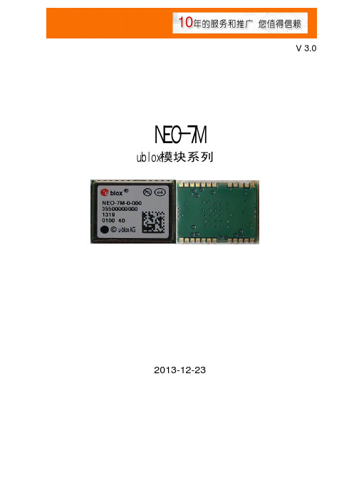
NEO-7Mublox模块系列V 3.0深圳市鹏城润发电子有限公司2013-12-23目 录1.产品描述.................................................................................................................-2- 2.产品型号编码规则..................................................................................................-3- 3.产品用应用范围及优点...........................................................................................-4- 4.技术特性................................................................................................................-5- 5.模块工作原理.........................................................................................................-6- 6.模块信号测试图和模块RF 射频图............................................................................-7- 6.1模块信号测试图...........................................................................................-7- 6.2模块RF 射频图...........................................................................................-7- 7.模块管脚分配........................................................................................................-8- 8.推荐应用电路.......................................................................................................-10- 9.模块设计注意事项................................................................................................-11- 10.模块焊盘尺寸.....................................................................................................-12- 11.NMEA 0183 协议. (13)11.1 GGA................................................................................................-14- 11.2 GLL.................................................................................................-15- 11.3 GSA ...............................................................................................-15- 11.4 GSV................................................................................................-16- 11.5 RMC...............................................................................................-17- 11.6 VTG. (17)12.经纬度转换....................................................................................................-18- 13-19- 14.产品包装.......................................................................................................-20- .SMT 温度曲线图.. (21)15.贴片注意事项................................................................................................NEO-7MGPS 产品名称1. 产品描述:模块是一个低功耗主芯片的超小外型GPS 接收模组,该产品采用了新一代U-blox 芯片,超高灵敏度,具备全方位功能,能满足专业定位的严格要求。
Micro Motion 5700 型变送器(带可配置输入和输出)安装手册说明书
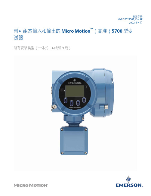
安装手册MMI-20027507, Rev AF2022 年 4 月带可组态输入和输出的 Micro Motion™(高准)5700 型变送器所有安装类型(一体式、4 线和 9 线)安全信息本手册提供的安全信息用于保护人员和设备。
在进行下一步操作前,请仔细阅读每条安全信息。
安全和认证信息如按照本手册中的说明正确安装,则高准产品符合所有适用的欧洲指令。
请参阅 EU 符合性声明,以了解本产品适用了哪些指令。
附带以下文档:针对所有相关欧洲指令的 EU 符合性声明,以及全套 ATEX 安装图纸和说明书。
此外,还可以访问网站或通过您的当地高准支持中心,获取适用于欧盟以外地区安装的 IECEx 安装说明以及适用于北美地区安装的CSA 安装说明。
符合压力设备指令的设备所附的信息可通过网站获取。
在欧洲的危险环境安装,如果本国没有相关标准,则可参考标准 EN 60079-14。
其他信息如需获得故障排查信息,请参阅组态手册。
产品样本和手册可从高准网站获取。
退货政策退回设备时必须遵循高准程序。
遵循这些程序可确保符合政府运输机构的法规要求,同时有助于为高准员工提供安全的工作环境。
如未遵循高准返修程序,高准将不会接受返回的设备。
有关于返修程序和返修表格,请登录获取,或致电高准客户服务部门获取。
2安装手册内容MMI-200275072022 年 4 月内容第章1开始之前 (5)1.1 关于本手册 (5)1.2 风险说明 (5)1.3 相关文档 (5)第章2安装准备 (7)2.1 安装检查表 (7)2.2 改装现有安装的其他注意事项 (8)2.3 电源要求 (9)第章3安装和传感器接线 (11)3.1 一体化安装变送器安装和传感器接线 (11)3.2 安装变送器 (11)3.3 分体式变送器与传感器的接线 (15)3.4 仪表部件接地 (17)3.5 旋转传感器上的变送器(可选) (18)3.6 旋转变送器上的用户界面(可选) (20)3.7 旋转远程安装变送器(可选)上的传感器接线盒 (21)第章4通道接线 (23)4.1 可用通道 (23)4.2 查看接线通道 (23)4.3 毫安输出接线 (24)4.4 毫安/HART®输出接线 (26)4.5 频率输出接线 (28)4.6 给离散输出布线 (31)4.7 RS-485 输出接线 (34)4.8 毫安输入接线 (35)4.9 给离散输入布线 (36)4.10 频率输入接线 (37)4.11 为安全仪表系统 (SIS) 应用进行通道 A 和 D 的接线 (38)第章5电源接线 (43)第章6打印机接线 (45)第章7接通变送器电源 (47)第章8利用设置向导组态变送器 (49)第章9使用显示控制 (51)安装手册3内容安装手册2022 年 4 月MMI-20027507第章10可用服务端口连接 (53)附录 A将高准 5700 型变送器连接到高准 3100 型变送器 (55)4带可组态输入和输出的 Micro Motion(高准)5700 型变送器1开始之前1.1关于本手册本手册提供有关高准 5700 变送器规划、安装、接线和初始设置的信息。
常用三极管参数表
10
300
DAUL
MMDT1036
P*2
-40
-32
500
200
100
300
-150
-10
-0.4
-150
-15
200
DAUL
MMDT1037
P*2
-60
-50
150
200
120
820
-1
-6
-0.5
-1
-5
140
DAUL
MMDT3906
P*2
-40
-40
200
200
100
300
-10
-1
-0.25
-300
-300
-500
225
40
MMBTA94 PNP
-400
-400
-150
350
75
MMBTH10 NPN
20
15
50
225
60
GT85C
NPN
50
45
800
225
100
GTD82NS NPN
40
30
3000
1000
30
GTB72PS
PNP
-40
-30
-3000
1000
30
SC5094
NPN
18
40
40
600
225
100
300
150
10
0.5
380
10
300
40
500
225
40
120
10
1
0.25
10
1
Milltronics MSP-7 重型3线感应传感器概述说明书

Motion sensorsOverviewMilltronics MSP-7 Motion sensorMotion sensorsMilltronics MSP-7 Motion sensor6/27Milltronics MSP-7 is a heavy-duty 3-wire motion sensor that provides an NPN open collector output to PLCs.•Up to 100 mm (4 inch) gap between target and probe •Corrosion resistant construction•General purpose, suitable for majority of industrial applications;rugged probe designs provide unmatched reliabilityThe MSP-7 motion sensing probe can detect changes in the rotation and movement of ferrous equipment. When connected to a PLC it can warn of malfunction and signals to stop or slow down equipment, preventing costly failure or downtime. Its reliability makes it a very cost effective sensor.The single setpoint system suits most industrial applications. This versatile unit can be used on tail pulley shafts, driven pulleys, motor shaft sensing, belt or drag conveyors, screw conveyor flights, bucket elevators, fans and pumps.An NPN open collector 3-wire output allows for versatile connection to most PLC models and a large dynamic range ensures that the MSP-7 can detect changes in target speed for a variety of applications.•Key Applications: tail pulleys, motor shaft sensing, screw conveyor flights, bucket elevatorsMounting for Milltronics MSP-7, dimensions in mm (inch)Siemens FI01 · 2023Process Protection© Siemens AG 2023Motion sensorsMilltronics MSP-7 Motion sensor6/281) No Y01 needed in Order code for standard length.Siemens FI01 · 2023Process ProtectionMotion sensorsMilltronics MSP-7 Motion sensor6/29Stand-alone probe Milltronics MSP-7, dimensions in mm (inch)Siemens FI01 · 2023Process Protection。
Thermflow T777 - 应用指南说明书
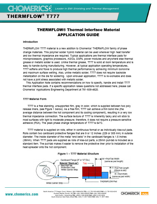
THERM FLOW T777 - Application GuideTHERMFLOW® Thermal Interface MaterialAPPLICATION GUIDEIntroductionTHERMFLOW T777 material is a new addition to Chomerics’ THERMFLOW family of phase change materials. This polymer solder hybrid material can be used wherever high heat transfer and low thermal impedance are required. Typical applications are thermal interface pads formicroprocessors, graphics processors, ASICs, DSPs, power modules and anywhere else thermal grease or metallic solder is used. Unlike thermal grease, T777 is solid at room temperature and is easy to handle during manufacturing. However, at typical application operating temperatures, T777 softens and flows to produce high thermal performance by achieving minimum bond-line and maximum surface wetting. Also, unlike metallic solder, T777 does not require backsidemetallization on the die for soldering. Upon end-user application, T777 is re-workable and does not have a joint stress associated with metallic solder.This Application Note contains recommendations on how to specify, handle and install T777 thermal interface pads. If a specific application raises questions not addressed here, please call Chomerics’ Applications Engineering Department at 781-939-4620.T777 Material FormT777 is a free standing, unsupported film, gray in color, which is supplied between two poly release liners, (see Figure 1 below). As a free film, T777 can achieve a thin bond line (theaverage distance between the hot component and its cooling component), resulting in a very low thermal impedance connection. The surface texture of T777 is inherently tacky and will stick to most surfaces with light to moderate pressure; therefore, it does not require a pressure sensitive adhesive (PSA). The peak phase change temperature of T777 is 64°C.T777 material is supplied on rolls, either in continuous format or as individually kiss-cut pads. Rolls contain two cardboard protective flanges that are 9 or 12 inches (229 or 305 mm) in outside diameter. The inside diameter of the metal “end bells” in the cardboard flanges is 1.5 inches(38mm). When T777 pads are supplied as rolls of kiss-cut parts, a 25mm pull-tab is included as a standard item. The pull-tab makes it easier to remove the protective liner prior to installation of the heat spreader onto the hot component.Figure 1 – T777 Material StructureLeader in EMI Shielding and Thermal ManagementTHERMFLOW ® T777Mounting Surface PreparationThe mounting surface, usually the heat sink, spreader, pipe or its integrated form, should be clean and free from machining oils and aluminum dust, and may be cleaned with any common solvent, such as isopropyl alcohol (IPA) if necessary. The surface of the heat cooling component may be anodized, chromate coated or unfinished aluminum.Cutting of T777 PadsT777 material is supplied in one of the forms noted above. Chomerics can slit roll stock T777 material to the width required by the customer. However, the minimum slitting width for T777 material is 0.5 inches (12.5mm) wide with a tolerance of +/-0.02 inches (+/-0.5mm). Individually kiss-cut pieces are limited to pads no smaller than 0.4 inches (10mm) in width or length. Standard length and width tolerances for individual cut pieces are also +/-0.02 inches (+/-0.5mm). For custom widths, please contact your Chomerics Representative, or call Chomerics’ Applications Engineering at 781-939-4620 to discuss size and tooling options.T777 Pad Size SelectionA T777 pad softens and flows under the temperature and pressure conditions encountered in a typical application between a hot component and its cooling component. During the initial power cycle, as the T777 pad softens and flows to displace air in the interface gap, the average thickness of the pad will decrease and the total area covered by the pad will increase. Typical increase will be on the order of 30% in length and width, or about 60% in area. This 30%length/width increase was determined using a “generic” heat sink, its associated metal spring clip, and a microprocessor device with integrated heat spreader. The goal is to fully cover the footprint of the heat generating device. Each application will vary in terms of flatness, co-planarity, applied clamping pressure, operating temperature, pad-to-spreader placement tolerance, spreader-to-component placement tolerance, etc., so it is recommended that the pad size is verified through actual testing to be sure that thermal requirements are met.Installation of T777 PadsT777 material does not require pre-heating of the (integrated) heat spreader prior to installing the T777 pad onto the heat spreader substrate. The inherent “sticky or tacky” nature of T777 is sufficient for the pad to adhere to the substrate surface. However, due to the phase change nature of the T777 material, please follow the process temperature/pressure guidelines below to ensure the best results for a specific assembly process:Installation of T777 Pads (Continued)Table 1 – Recommended Installation Temperatures and PressuresTypical T777 Pad Installation Steps1. If necessary, clean the (integrated) heat spreader or heat sink base of any machineoils, greases, hand oils, or other contaminants. Wipe with a solvent such as isopropyl alcohol, MEK, or toluene.2. Peel the T777 pad (with release liner and pull-tab still in place) from the white carrierstrip.3. Place the T777 pad on the heat spreader/heat sink with the tacky side down andapply pressure on the protective release liner side to ensure intimate “wetting” of the T777 pad to the surface. This pressure, approximately 3,000 grams (6 pounds) on a 1-inch by 1-inch (25.4 x 25.4 mm) pad can typically be achieved manually by rolling a soft rubber wheel (e.g. a small wallpaper roller) back and forth over the pad. Table 1 above gives some recommended temperature/pressure conditions for best installation performance.4. The protective release liner serves to prevent the T777 pad from beingcontaminated with dirt and dust during shipping/handling of the heat spreader component to the final system assembly location. The protective liner should be removed just prior to mounting the heat spreader onto the microprocessor component.5. When removing the pull-tab, use a quick, lifting motion. This is preferable to peelingthe pull-tab from the T777 pad and heat spreader. To ensure optimal “wetting” of the T777 pad to the heat spreader, it is recommended that the parts be allowed to dwell one hour prior to attempting protective liner removal.6. With heat spreader and gray unprotected T777 pad in place on the component,install clip, screws or mechanical fasteners.Process Step Recommended Range Removing pad from white carrier liner Temp of Roll: less than 100°F (38°C) Installing pad onto “cold” heat sinkHeat Spreader Temp: 60°F to 100°F (16°C to 38°C) Roll Temp: 70°F to 100°F (21°C to 38°C) *installation Pressure: 25 to 50 psi Installing pad onto “warm” heat sink Heat Spreader Temp: 75°F to 100°F (24°C to 38°C) Roll Temp: 70°F to 100°F (21°C to 38°C) *installation Pressure: 5 to 10 psiRemoving protective release linerTemp of Heat Spreader /Pad Assembly: Less than 100°F (38°C) *Apply pressure to the pad with a soft “press-pad” for 2 to 3 secondsFigure 2 – Peel and Stick Application of T777 MaterialAutomated Installation of T777 PadsChomerics has developed several versions of automated pad installation equipment. Contact Chomerics’ Applications Engineering at 781-939-4620 to determine the best approach for a specific component/heat spreader/sink configuration and assembly process.Material Storage and ShippingT777 is a temperature sensitive material, and should be stored below 35°C(95°F). Short term exposure to higher temperatures, up to 45°C (113°F) during product shipment will not affect product performance.It is recommended that rolls of THERMFLOW material be stored with release liner pull-tabs such that the roll is resting on the THERMFLOW material not on the pull-tabs. In this orientation there is no weight pressing down onto the pull-tab material, thus preventing wrinkling of the pull-tabs and possible “telescoping” of the wound roll.Initial Re-Flow of T777As with any (PCM) phase change material, T777 material requires an initial phase change to achieve optimum thermal performance. Initial thermal performance will behave as a dry joint thermal interface, because the material has not yet driven out the air gaps between the heat spreader and the component. Re-flow and wetting of the surfaces typically takes only a few minutes once the 64°C phase change temperature is achieved. Also, allowing the monitored electronic component to reach 75°C, the T777 pad would fully change phase for maximum wetting. Pressure enhances and accelerates the effect. After this initial re-flow, the interface resistance will behave as high performance thermal grease, even after powering down of the microprocessor. Unless the heat spreader is removed from the component (for upgrades, re-work, etc.) the initial high interface resistance will not be seen during subsequent power cycles.Rework InformationTypically, the heat spreader can be separated from the component with the help of a mini screwdriver, without elevating the temperature. If heating is possible, it will facilitate the separation of the heat spreader from the component. If heating is used, then first allow the heat spreader and component to cool down. A razor blade can then be used to scrape the residualT777 material away. Chemically, the residual T777 can be softened with either MEK (methyl ethyl ketone), or IPA (isopropanol), or toluene. The residual material can be removed by wiping with a cloth.。
tmm-7

图6-13 工件在两顶尖上定位
一平面和其垂直的孔的组合定位 30
6.2.1 常用定位方法与定位元件
一面两孔定位
采用一个大平面和垂直于该平面的两个圆孔定位
定位元件 ——一个圆柱销和一个菱形销
菱形销的宽度的计算
D2 2 m in ( 6-2) b T1k T1x 1m in
式中 b —— 菱形销宽度 D2 —— 工件上与菱形销配合孔的最小直径 Δ1min,Δ2min —— 孔1与销1和孔2与销2的最小间隙 T1k ,T1x —— 两孔中心距和两销中心距的公差
ΔDW = (Dmax- Dmin) =
2
1 1 2
TD
(6-4)
Dmin
此时,孔在销上的定位已由定心 定位转化为支承定位的形式,定位 基准也由孔心变成了与定位销固定 边接触的一条母线。这种情况下, 定位误差是由于定位基准与工序基 准不重合所造成的,属于基准不重 合误差,与定位销直径无关。
ΔDW
O O2
O1
图6-17 孔与销间隙配合 固定边接触时定位误差
36
6.2.2 定位误差
2. 用微分方法计算定位误差 【例6-4】工件在V型块上定位铣键槽,计算定位误差 【解】要求保证的工序尺寸和工序要求:①槽底至工件外 圆中心的距离H(或槽底至外圆下母线的距离H1,或槽底至 外圆上母线的距离H2 );②键槽对工件外圆中心的对称度
6
通用夹具
三爪卡盘
四爪卡盘
万向平口钳
回转工作台
分度头
7
专用夹具
L 3 φD
4
零件工序简图
8
成组夹具
KH1 KH2 KH3 KH4
L 3 φD 3 L φD
4 L 3
PL33-M-7検査作业标准书中文.

成品质量管理项目No.12345无暇弊划痕长度宽度范围数量No 确认项目12修改年月日修改理由3mm以内目视抽样检验表0.1mm以内制造商机种名部件名6工作标准书发行日年日2012工作标准书NONo.月龙鼻/工作顺序工作要点辨别标准(图解异常.问题.不良品等发生时的措施及应对方法工作项成品外观检查sammy株式会社PL0825頻度检验方法记录测定者作成确认承认对于PLM品质管理担当者的报告检验标准抽样检验表操作者1注入口处理0.2mm以下2异物.伤痕参见下表規格4/小时全数目视.触摸目视抽样检验表操作者3融合不良斑无 ※1 (申请样品)4/小时目视抽样检验表操作者操作者5喷气痕无 ※1 (申请样品)4/小时目视抽样检验表操作者4皱褶.流痕无 ※1 (申请样品)4/小时目视抽样检验表无 ※1 (申请样品)4/小时操作者7歪曲.变形无 ※1 (申请样品)4/小时治具确认抽样检验表操作者6凹凸抽样检验表操作者9充填不足无 ※1 (申请样品)4/小时目视抽样检验表操作者810白痕无 ※1 (申请样品)4/小时目视.触摸瑕癖.飞边无 ※1 (申请样品)4/小时目视抽样检验表操作者11灼痕.变色无 ※1 (申请样品)4/小时目视抽样检验表操作者4/小时测针,目视抽样检验表操作者破损.裂痕无 ※1 (申请样品)4/小时目视14抽样检验表操作者13安装孔.位置决定打孔正常16操作者※1根据发生数量,位置,使用部位,结构 决定厂内限度。
且 对客户进行特殊采用的申请后决定限度。
重量测量注入管規 格透镜类透镜以外部分可见范围外(背面部件以外)電子量抽样检验表単重量13.27 g4/小时可见范围外(背面部件)其他异物面积规格0.1mm2以下0.2mm2以下0.3mm2以下0.5mm2以下明显者不可范围明显者不可0.1mm以内0.2mm以内0.3mm以内相隔10mm以上异物,划痕合计2个异物,划痕合计5个异物,划痕合计5个异物,划痕合计3个※ 成品重量测量附带注入管重量成品单重量 ±0.03g0.00 g11.09 g修改年月日修改理由2mm以内5mm以内相隔10mm以上数量异物,划痕合计2个异物,划痕合计3个异物,划痕合计5个异物,划痕合计5个10mm以内歪曲变形的确认注入口的检查螺丝帽部的检查树脂色的检查无由于树脂烧焦,气体而产生的触觉上没有划感(不留毛边)瑕弊的检查测针入底。
赛米控丹佛斯 SEMITRANS 2 650V 类型 SKM75GB07E3 数据表

Absolute Maximum Ratings Symbol Conditions Values UnitIGBT V CES T j = 25 °C 650 V I C T j = 175 °CT c = 25 °C 99 A T c = 80 °C74 A I Cnom 75 A I CRM225 A V GES -20 (20)V t psc V CC = 360 V V GE ≤ 15 V V CES ≤ 650 VT j = 150 °C6 μs T j-40 (175)°C Inverse diode V RRM T j = 25 °C 650V I FT j = 175 °CT c = 25 °C 84A T c = 80 °C62 A I FRM 100A I FSM t p = 10 ms, sin 180°,T j = 25 °C550A T j-40 ... 175°C Module I t(RMS)200 A T stg module without TIM-40 ... 125 °C V isolAC sinus 50 Hz, t = 1 min4000VCharacteristics Symbol Conditions min. typ. max. UnitIGBT V CE(sat)I C = 75 A V GE = 15 V chiplevel T j = 25 °C 1.45 1.77 V T j = 150 °C 1.72 2.10 V V CE0chiplevel T j = 25 °C 0.90 1.00 V T j = 150 °C 0.82 0.90 V r CE V GE = 15 V chiplevelT j = 25 °C 7.3 10 mΩ T j = 150 °C12 16 mΩ V GE(th)V GE = V CE , I C = 1.2 mA5.15.86.4 V I CES V GE = 0 V, V CE = 650 V, T j = 25 °C0.3mA C ies V CE = 25 V V GE = 0 Vf = 1 MHz4.6 nF C oes f = 1 MHz 0.30 nF C res f = 1 MHz0.14 nF Q G V GE = - 8V ... + 15 V 680 nC R Gint T j = 25 °C 4.0 Ω t d(on)V CC = 300 V I C = 75 AV GE =+15/-15V R Gon = 1 Ω R Goff = 1 Ωdi/dt on = 2500 A/µs di/dt off = 1250 A/µs dv/dt = 4030 V/µs T j = 150 °C 72 ns t r T j = 150 °C 30 ns E on T j = 150 °C 2.4 mJ t d(off)T j = 150 °C 250 ns t f T j = 150 °C 50 ns E off T j = 150 °C2.7mJ R th(j-c)per IGBT0.591K/W R th(c-s)per IGBT, P12 (reference)0.090 K/W R th(c-s)per IGBT, HP-PCM0.050K/WTrench IGBT ModulesSKM75GB07E3 Features*∙V CE(sat) with positive temperature coefficient∙ High short circuit capability, self limiting to 6 x I Cnom∙ Fast & soft switching inverse CAL diodes∙ Insulated copper baseplate using DCB Technology (Direct Copper Bonding)∙ With integrated gate resistorTypical Applications∙ AC inverter drives ∙ UPS∙ Electronic welders ∙ Wind power ∙ Public transportRemarks∙ Case temperature limited to T c = 125°C max.∙Recommended T op = -40 ... +150°C ∙Product reliability results valid for T j = 150°C∙Use of soft R G necessaryGBSEMITRANS ® 2Characteristics Symbol Conditions min. typ. max. UnitInverse diode V F = V EC I F = 75 A V GE = 0 V chiplevel T j = 25 °C 1.37 1.73 V T j = 150 °C 1.35 1.72 V V F0chiplevel T j = 25 °C 1.04 1.24 V T j = 150 °C 0.85 0.99 V r F chiplevelT j = 25 °C 6.7 9.8 mΩ T j = 150 °C10 15mΩ I RRM V CC = 300 V I F = 75 AV GE = -15 Vdi/dt off = 2740 A/µs T j = 150 °C 87 A Q rr T j = 150 °C7.8 µC E rr T j = 150 °C 1.6mJ R th(j-c)per diode0.85K/W R th(c-s)per diode, P12 (reference) 0.108K/W R th(c-s)per diode, HP-PCM0.059K/W Module L CE 30nH R CC'+EE'measured per switchT j = 25 °C 0.65mΩ T j = 150 °C1.09 mΩ R th(c-s)1calculated without thermal coupling, P12 (reference)0.025 K/W R th(c-s)2including thermal coupling,T s underneath module, P12 (reference)0.040 K/W R th(c-s)2including thermal coupling,T s underneath module, HP-PCM 0.022K/W M s to heat sink M635 Nm M t to terminal M52.55 Nm -Nm w160 gSEMITRANS ® 2 Trench IGBT ModulesSKM75GB07E3 Features*∙V CE(sat) with positive temperature coefficient∙ High short circuit capability, self limiting to 6 x I Cnom∙ Fast & soft switching inverse CAL diodes∙ Insulated copper baseplate using DCB Technology (Direct Copper Bonding)∙ With integrated gate resistorTypical Applications∙ AC inverter drives ∙ UPS∙ Electronic welders ∙ Wind power ∙ Public transportRemarks∙ Case temperature limited to T c = 125°C max.∙Recommended T op = -40 ... +150°C ∙Product reliability results valid for T j = 150°C∙Use of soft R G necessaryGBFig. 1: Typ. output characteristic, inclusive R CC'+ EE'Fig. 2: Rated current vs. temperature I C = f (T C )Fig. 3: Typ. turn-on /-off energy = f (I C ) Fig. 4: Typ. turn-on /-off energy = f (R G )Fig. 5: Typ. transfer characteristic Fig. 6: Typ. gate charge characteristicFig. 7: Typ. switching times vs. I C Fig. 8: Typ. switching times vs. gate resistor R GFig. 9: Transient thermal impedance Fig. 10: Typ. CAL diode forward charact., incl. R CC'+ EE'Fig. 11: CAL diode peak reverse recovery current Fig. 12: Typ. CAL diode peak reverse recovery chargePinout and DimensionsGBThis is an electrostatic discharge sensitive device (ESDS), international standard IEC 60747-1, chapter IX.*IMPORTANT INFORMATION AND WARNINGSThe specifications of SEMIKRON products may not be considered as guarantee or assurance of product characteristics ("Beschaffenheitsgarantie"). The specifications of SEMIKRON products describe only the usual characteristics of products to be expected in typical applications, which may still vary depending on the specific application. Therefore, products must be tested for the respective application in advance. Application adjustments may be necessary. The user of SEMIKRON products is responsible for the safety of their applications embedding SEMIKRON products and must take adequate safety measures to prevent the applications from causing a physical injury, fire or other problem if any of SEMIKRON products become faulty. The user is responsible to make sure that the application design is compliant with all applicable laws, regulations, norms and standards. Except as otherwise explicitly approved by SEMIKRON in a written document signed by authorized representatives of SEMIKRON, SEMIKRON products may not be used in any applications where a failure of the product or any consequences of the use thereof can reasonably be expected to result in personal injury. No representation or warranty is given and no liability is assumed with respect to the accuracy, completeness and/or use of any information herein, including without limitation, warranties of non-infringement of intellectual property rights of any third party. SEMIKRON does not assume any liability arising out of the applications or use of any product; neither does it convey any license under its patent rights, copyrights, trade secrets or other intellectual property rights, nor the rights of others. SEMIKRON makes no representation or warranty of non-infringement or alleged non-infringement of intellectual property rights of any third party which may arise from applications. Due to technical requirements our products may contain dangerous substances. For information on the types in question please contact the nearest SEMIKRON sales office. This document supersedes and replaces all information previously supplied and may be superseded by updates. SEMIKRON reserves the right to make changes.。
- 1、下载文档前请自行甄别文档内容的完整性,平台不提供额外的编辑、内容补充、找答案等附加服务。
- 2、"仅部分预览"的文档,不可在线预览部分如存在完整性等问题,可反馈申请退款(可完整预览的文档不适用该条件!)。
- 3、如文档侵犯您的权益,请联系客服反馈,我们会尽快为您处理(人工客服工作时间:9:00-18:30)。
Lead-free Green
MMDT2227M
COMPLEMENTARY NPN / PNP SMALL SIGNAL SURFACE MOUNT TRANSISTOR
·Complementary Pair
·Epitaxial Planar Die Construction ·One 2222A Type (NPN), One 2907A Type (PNP)
·Ideal for Low Power Amplification and Switching ·Lead Free By Design/RoHS Compliant (Note 2)·
"Green Device" (Note 3)
Features
Maximum Ratings, 2222A Type (NPN)
@ T A = 25°C unless otherwise specified
Mechanical Data
·Case: SOT-26
·Case Material: Molded Plastic, “Green” Molding
Compound. UL Flammability Classification Rating 94V-0·Moisture Sensitivity: Level 1 per J-STD-020C ·Terminals: Finish - Matte Tin annealed over Copper leadframe. Solderable per MIL-STD-202, Method 208·Terminal Connections: See Diagram
·Ordering & Date Code Information: See Page 3·Marking (See Page 3): K27·
Weight: 0.006 grams (approximate)
Note: 1. Device mounted on FR-4 PCB, 1 inch x 0.85 inch x 0.062 inch; pad layout as shown on Diodes Inc. suggested pad layout document AP02001, which can be found on our website at /datasheets/ap02001.pdf. 2. No purposefully added lead.
3. Diodes Inc.'s "Green" policy can be found on our website at /products/lead_free/index.php.
Maximum Ratings, 2907A Type (PNP)
@ T A = 25°C unless otherwise specified
Note: E1, B1, and C1 = 2907A Type (PNP), E2, B2, and C2 = 2222A Type (NPN).
Type marking indicates orientation.
Maximum Ratings, Total
@ T A = 25°C unless otherwise specified
Electrical Characteristics, 2222A Type (NPN)@ T A = 25°C unless otherwise specified
Note: 4.Pulse test: Pulse width £ 300m s, duty cycle £ 2%.
Note: 6. For Packaging Details, go to our website at /datasheets/ap02007.pdf.
Electrical Characteristics, 2907A Type (PNP)
@ T A = 25°C unless otherwise specified Note:
5. Short duration pulse test used to minimize self-heating effect.
Date Code Key
K27 = Product Type Marking Code YM = Date Code Marking Y = Year ex: S = 2005
M = Month ex: 9 = September
Marking Information
Ordering Information
(Note 6)
1.010
0.1
101.050
C A P A C I T A N C E (p F )
V , REVERSE VOLTS (V)R Fig. 1 (2222A) Typical Capacitance
Cobo
100
Cibo
0.001
0.01
1
10
0.1
100
0.20.40.60.81.01.21.41.61.82.0I BASE CURRENT (mA)
B,Fig. 2 (2222A) Typical Collector Saturation Region
V C O L L E C T O R -E M I T T E R V O L T A G E (V )
C E I = 1mA
C I = 10mA
C I = 30mA
C I = 100mA
C I = 300mA
C 110
100
C A P A C I T A N C E (p F )
V , REVERSE VOLTS (V)
R Fig. 3 (2907A) Typical Capacitance
I BASE CURRENT (mA)
B,Fig. 4 (2907A) Typical Collector Saturation Region
V C O L L E C T O R -E M I T T E R V O L T A G E (V )
C E -0.20
-1.0-1.2-1.4
-1.6-0.01-0.001
-1-10-0.1-100
IMPORTANT NOTICE
Diodes Incorporated and its subsidiaries reserve the right to make modifications, enhancements, improvements, corrections or other changes without further notice to any product herein. Diodes Incorporated does not assume any liability arising out of the application or use of any product described herein; neither does it convey any license under its patent rights, nor the rights of others. The user of products in such applications shall assume all risks of such use and will agree to hold Diodes Incorporated and all the companies whose products are represented on our website, harmless against all damages.
LIFE SUPPORT
Diodes Incorporated products are not authorized for use as critical components in life support devices or systems without the expressed written approval of the President of Diodes Incorporated.。
