IPD50N06S3-07中文资料
数据手册_HR7P187_Datasheet_C V2.1

加强描述:3.2.3,5.1.4,6.1.3,6.5.1,6.5.2, 附录 1.1,附录 2.1,附录 2.2
错误修正:2.1,2.2,4.3,5.1.1.1,5.1.1.2,5.1.2.1, 5.1.2.2,5.4.3,附录 1.3,附录 1.4
V2.1 版权所有©上海海尔集成电路有限公司
4/85
V2.1 版权所有©上海海尔集成电路有限公司
3/85
上海海尔集成电路有限公司
HR7P187 数据手册
版本 V1.0 V2.0
V2.1
修改日期 2010-08-02 2011-03-11
2011-04-26
修订历史
预发行版
更改概要
添加内部时钟电气特性及部分补充说明
2/85
上海海尔集成电路有限公司
HR7P187 数据手册
产品订购信息
型号
程序存储器
HR7P187F4R HR7P187F4R-B
HR7P187F4D HR7P187F4D-B FLASH:2K×15 位
HR7P187F4S HR7P187F4S-B
数据存储器
版权所有©
上海海尔集成电路有限公司
本数据手册的信息在发行时是经过核实并且尽最大努力使之精确的。上海海尔集成电路有限公司不为由于使用本数 据手册而可能带来的风险或后果负责。手册中的实例仅作为说明用途,上海海尔集成电路有限公司不担保或确认这 些实例是合适的、不需进一步修改的、或推荐使用的。上海海尔集成电路有限公司保留不需要通知本数据手册读者 而修改自己产品的权利。如需得到最新的产品信息,请随时用上述联系方式与上海海尔集成电路有限公司联系。
上海海尔集成电路有限公司
HR7P187 数据手册
SG50N06DS中文资料

Characteristic Values min. 600 2.5 5 200 1 ±100 2.5 typ. max.
Unit V V uA mA nA V
VCE=0V; VGE=±20V IC=IC90; VGE=15V
SG50N06S, SG50N06DS
Discrete IGBTs
(TJ=25oC, unless otherwise specified) Symbol Test Conditions Characteristic Values min. gts IC=IC90; VCE=10V Pulse test, t Cies Coes Cres Qg Qge Qgc td(on) tri td(off) tfi Eoff td(on) tri Eon td(off) tfi Eoff RthJC RthCK 0.05 Inductive load, TJ=25 C IC=IC90; VGE=15V; L=100uH VCE=0.8VCES'; RG=Roff=2.7 Remarks:Switching times may increase for VCE(Clamp) 0.8VCES' higher TJ or increased RG Inductive load, TJ=125 C IC=IC90; VGE=15V; L=100uH VCE=0.8VCES'; RG=Roff=2.7 Remarks:Switching times may increase for VCE(Clamp) increased RG 0.8VCES' higher TJ or
o o
Unit
typ. 35
max. S
25 2%
RE50分布式总线IO通用产品(产品手册)v0.1
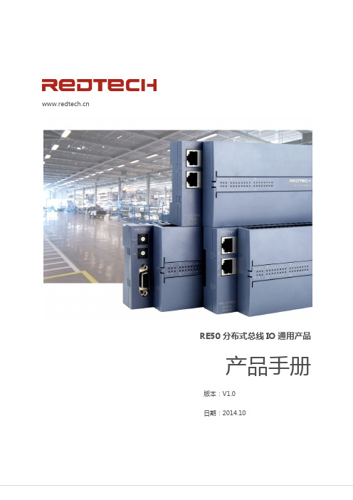
RE50 分布式总线 IO 通用产品
产品手册
版本:V1.0 日期:2014.10
RE50 分布式总线 IO 通用产品手册
警告提示
为了您的人身安全以及避免财产损失,必须注意本手册中的提示。人身安全的提示用一个警告 三角表示,仅与财产损失有关的提示不带警告三角。警告提示根据危险等级由高到低,如下表 示。
小心
表示如果不采取相应的小心措施,可能导致轻微的人身伤害。
注意
表示如果不采取相应的小心措施,可能导致财产损失。 当出现多个危险等级的情况下,每次总是使用最高等级的警告提示。如果在某个警告提示中带
2 / 120
RE50 分布式总线 IO 通用产品手册
有警告可能导致人身伤害的警告三角,则可能在该警告提示中另外还附带有可能导致财产损失 的警告。
关于著作权及商标的记述
〉本手册的著作权归沈阳瑞德泰科电子有限公司所有。 〉绝对禁止对本书的随意复制。 〉其他公司及产品名是各公司的商标或注册商标。
责任免除
〉我们已对印刷品中所述内容与硬件和软件的一致性作过检查,但不排除存在偏差的可能性, 因此我们不保证印刷品中所述内容与硬件和软件完全一致。印刷品中的数据都按规定经过检测, 必要的修正值包含在下一版本中。 〉因商品改良,规格、外观及手册内容会有所更改,恕不另行通知,敬请谅解。
本手册目的............................................................................................................................................. 4 需要的基本知识..................................................................................................................................... 4 本手册适用范围..................................................................................................................................... 4 技术支持................................................................................................................................................. 4
50N06中文资料
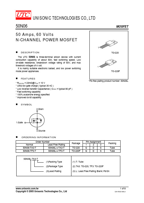
UNISONIC TECHNOLOGIES CO., LTD50N06MOSFET50 Amps, 60 VoltsN-CHANNEL POWER MOSFETDESCRIPTIONThe UTC 50N06 is three-terminal silicon device with current conduction capability of about 50A, fast switching speed. Low on-state resistance, breakdown voltage rating of 60V, and max threshold voltages of 4 volt.It is mainly suitable electronic ballast, and low power switching mode power appliances.FEATURES* R DS(ON) = 23m Ω@V GS = 10 V* Ultra low gate charge ( typical 30 nC )* Low reverse transfer Capacitance ( C RSS = typical 80 pF ) * Fast switching capability* 100% avalanche energy specified * Improved dv/dt capabilitySYMBOL1.GateTO-22011TO-220F*Pb-free plating product number: 50N06LORDERING INFORMATIONOrder Number Pin AssignmentNormalLead Free Plating Package 1 2 3 Packing50N06-TA3-T 50N06L-x-TA3-T TO-220 G D S Tube 50N06-TF3-T 50N06L-x-TF3-T TO-220F G D S TubeABSOLUTE MAXIMUM RATINGSPARAMETER SYMBOL RATINGS UNITDrain-Source Voltage V DSS 60 V Gate to Source Voltage V GSS ±20 VT C = 25 50 AContinuous Drain Current T C = 100 I D35 ADrain Current Pulsed (Note 1) I DM 200 A Single Pulsed Avalanche Energy (Note 2) E AS 480 mJ Repetitive Avalanche Energy (Note 1) E AR 13 mJ Peak Diode Recovery dv/dt (Note 3) dv/dt 7 V/nsTotal Power Dissipation (T C = 25 ) 130 WDerating Factor above 25P D0.9 W/ Operation Junction Temperature T J -55 ~ +150 Storage Temperature T STG -55 ~ +150 Note: Absolute maximum ratings are those values beyond which the device could be permanently damaged.Absolute maximum ratings are stress ratings only and functional device operation is not implied.THERMAL DATAPARAMETER SYMBOL MIN TYP MAX UNITThermal Resistance, Junction-to-Case θJC 1.15 °C/W Thermal Resistance, Case-to-Sink θCS 0.5 °C/W Thermal Resistance, Junction-to-Ambient θJA 62.5 °C/WELECTRICAL CHARACTERISTICS T C = 25 unless otherwise specifiedPARAMETER SYMBOL TEST CONDITIONS MIN TYP MAX UNIT Off CharacteristicsDrain-Source Breakdown Voltage BV DSS V GS = 0 V, I D = 250 µA 60 V Breakdown Voltage Temperature Coefficient BV DSS /△T J I D = 250 µA,Referenced to 250.07 V/V DS = 60 V, V GS = 0 V µADrain-Source Leakage Current I DSSV DS = 48 V, T C = 1251 µA Gate-Source Leakage Current V GS = 20V, V DS = 0 V 100 nAGate-Source Leakage Reverse I GSSV GS = -20V, V DS = 0 V -100 nA On Characteristics Gate Threshold Voltage V GS(TH) V DS = V GS , I D = 250 µA 2.0 4.0 V Static Drain-Source On-StateResistanceR DS(ON) V GS = 10 V, I D = 25 A 18 23 m ΩDynamic Characteristics Input Capacitance C ISS 900 1220 pFOutput Capacitance C OSS 430 550 pFReverse Transfer Capacitance C RSSV GS = 0 V, V DS = 25 Vf = 1MHz80 100 pF Dynamic Characteristics Turn-On Delay Time t D(ON) 40 60 nsRise Time t R 100 200 ns Turn-Off Delay Time t D(OFF) 90 180 nsFall Time t F V DD = 30V, I D =25 A, R G = 50Ω (Note 4, 5) 80 160 ns Total Gate Charge Q G 30 40 nCGate-Source Charge Q GS 9.6 nCGate-Drain Charge (Miller Charge) Q GD V DS = 48V, V GS = 10 VI D = 50A, (Note 4, 5)10 nC2. L=5.6mH, I AS=50A, V DD=25V, R G=0Ω, Starting T J=253. I SD≤50A, di/dt≤300A/µs, V DD≤BV DSS, Starting T J=254. Pulse Test: Pulse Width≤300µs,Duty Cycle≤2%5. Essentially independent of operating temperature.TEST CIRCUITS AND WAVEFORMSV DDV GS (Driver)I SD (D.U.T.)Body DiodeForward Voltage DropV DS(D.U.T.)Fig. 1A Peak Diode Recovery dv/dt Test CircuitFig. 1B Peak Diode Recovery dv/dt WaveformsTEST CIRCUITS AND WAVEFORMS (Cont.)R LDDV DS90%10%V GStFig. 2A Switching Test Circuit Fig. 2B Switching WaveformsFig. 3A Gate Charge Test CircuitFig. 3B Gate Charge Waveform10VLV DDI ASFig. 4A Unclamped Inductive Switching Test Circuit Fig. 4B Unclamped Inductive Switching WaveformsTYPICAL CHARACTERISTICS101010101010Drain -Source Voltage , V DS (V)D r a i n C u r r e n t , I D (A )On-State Characteristics101010Gate-Source Voltage , V GS (V)D r a i n C u r r e n t , I D (A )Transfer Characteristics0D r a i n -S o u r c e O n -R e s i s t a n c e , R D S (O N ) (m Ω)Drain Current , I D (A)4080200100140On-Resistance Variation vs . Drain Current102101000.2Source-Drain Voltage , V SD (V)R e v e r s e D r a i n C u r r e n t , I S D (A )On State Current vs. Allowable CaseTemperature1.60.40.60.8 1.0 1.2 1.420601201601805Drain -Source Voltage, V DC (V)C a p a c i t a n c e (p F )Capacitance Characteristics1020G a t e -t o -S o u r c e V o l t a g e , V G S (V )Total Gate Charge , Q G (nC)81012Gate Charge Characteristics64015253035TYPICAL CHARACTERISTICS(Cont.)-100D r a i n -S o u r c e B r e a k d o w n V o l t a g e , B V D S S (N o r m a l i z e d )Junction Temperature , T J (℃)-5050200100150Breakdown Voltage Variation vs . Junction, -5050100150On-Resistance Variation vs . 0Junction Temperature , T J (℃)101010Drain-Source Voltage , V DS (V)D r a i n C u r r e n t , I D ,(A )Maximum Safe Operating1010D r a i n C u r r e n t , I D (A )Case Temperature, T C (℃)7510050Maximum Drain Current vs . Case Temperature 01255025102030401010101010Square Wave Pulse Duration , t 1 (sec)T h e r m a l R e s p o n s e , Z θJ C (t )1010101010101010101Transient Thermal。
FAIRCHILD FQP50N06L 说明书

TO-220FQP SeriesGSDNotes:1. Repetitive Rating : Pulse width limited by maximum junction temperature2. L = 300µH, I AS = 52.4A, V DD = 25V, R G = 25 Ω, Starting T J = 25°C3. I SD ≤ 52.4A, di/dt ≤ 300A/µs, V DD ≤ BV DSS, Starting T J = 25°C4. Pulse Test : Pulse width ≤300µs, Duty cycle ≤2%5. Essentially independent of operating temperature∆BV DSS / ∆T J Breakdown Voltage Temperature CoefficientI D = 250 µA, Referenced to 25°C --0.06--V/°C I DSS Zero Gate Voltage Drain Current V DS = 60 V, V GS = 0 V ----1µA V DS = 48 V, T C = 150°C ----10µA I GSSF Gate-Body Leakage Current, Forward V GS = 20 V, V DS = 0 V ----100nA I GSSRGate-Body Leakage Current, ReverseV GS = -20 V, V DS = 0 V-----100nAOn CharacteristicsV GS(th)Gate Threshold Voltage V DS = V GS , I D = 250 µA1.0--2.5V R DS(on)Static Drain-Source On-ResistanceV GS = 10 V, I D = 26.2 AV GS = 5 V, I D =26.2 A ----0.0170.0200.0210.025Ωg FSForward TransconductanceV DS = 25 V, I D = 26.2 A --40--SDynamic CharacteristicsC iss Input Capacitance V DS = 25 V, V GS = 0 V, f = 1.0 MHz--12501630pF C oss Output Capacitance--445580pF C rssReverse Transfer Capacitance--90120pFSwitching Characteristicst d(on)Turn-On Delay Time V DD = 30 V, I D = 26.2 A,R G = 25 Ω--2050ns t r Turn-On Rise Time --380770ns t d(off)Turn-Off Delay Time --80170ns t f Turn-Off Fall Time --145300ns Q g Total Gate Charge V DS = 48 V, I D = 52.4 A,V GS = 5 V--24.532nC Q gs Gate-Source Charge --6--nC Q gdGate-Drain Charge--14.5--nCDrain-Source Diode Characteristics and Maximum RatingsI S Maximum Continuous Drain-Source Diode Forward Current ----52.4A I SM Maximum Pulsed Drain-Source Diode Forward Current----210A V SD Drain-Source Diode Forward Voltage V GS = 0 V, I S = 52.4 A ---- 1.5V t rr Reverse Recovery Time V GS = 0 V, I S = 52.4 A,dI F / dt = 100 A/µs --65--ns Q rrReverse Recovery Charge--125--nC(Note 4)(Note 4, 5)(Note 4, 5)(Note 4)Dimensions in MillimetersTRADEMARKSThe following are registered and unregistered trademarks Fairchild Semiconductor owns or is authorized to use and is not intended to be an exhaustive list of all such trademarks.DISCLAIMERFAIRCHILD SEMICONDUCTOR RESERVES THE RIGHT TO MAKE CHANGES WITHOUT FURTHER NOTICE TO ANY PRODUCTS HEREIN TO IMPROVE RELIABILITY, FUNCTION OR DESIGN. FAIRCHILD DOES NOT ASSUME ANY LIABILITY ARISING OUT OF THE APPLICATION OR USE OF ANY PRODUCT OR CIRCUIT DESCRIBED HEREIN;NEITHER DOES IT CONVEY ANY LICENSE UNDER ITS PATENT RIGHTS, NOR THE RIGHTS OF OTHERS.LIFE SUPPORT POLICYFAIRCHILD’S PRODUCTS ARE NOT AUTHORIZED FOR USE AS CRITICAL COMPONENTS IN LIFE SUPPORT DEVICES OR SYSTEMS WITHOUT THE EXPRESS WRITTEN APPROVAL OF FAIRCHILD SEMICONDUCTOR CORPORATION.As used herein:1. Life support devices or systems are devices or systems which, (a) are intended for surgical implant into the body,or (b) support or sustain life, or (c) whose failure to perform when properly used in accordance with instructions for use provided in the labeling, can be reasonably expected to result in significant injury to the user.2. A critical component is any component of a life support device or system whose failure to perform can be reasonably expected to cause the failure of the life support device or system, or to affect its safety or effectiveness.PRODUCT STATUS DEFINITIONS Definition of TermsDatasheet Identification Product Status DefinitionAdvance InformationFormative or In Design This datasheet contains the design specifications for product development. Specifications may change in any manner without notice.PreliminaryFirst ProductionThis datasheet contains preliminary data, andsupplementary data will be published at a later date.Fairchild Semiconductor reserves the right to make changes at any time without notice in order to improve design.No Identification Needed Full ProductionThis datasheet contains final specifications. Fairchild Semiconductor reserves the right to make changes at any time without notice in order to improve design.Obsolete Not In ProductionThis datasheet contains specifications on a product that has been discontinued by Fairchild semiconductor.The datasheet is printed for reference information only.ACEx™Bottomless™CoolFET™CROSSVOLT™DenseTrench™DOME™EcoSPARK™E 2CMOS™EnSigna™FACT™FACT Quiet Series™FAST ®FASTr™FRFET™GlobalOptoisolator™GTO™HiSeC™ISOPLANAR™LittleFET™MicroFET™MICROWIRE™OPTOLOGIC™OPTOPLANAR™PACMAN ™POP™PowerTrench ®QFET™QS™QT Optoelectronics™Quiet Series™SLIENT SWITCHER ®SMART START™Stealth™SuperSOT™-3SuperSOT™-6SuperSOT™-8SyncFET™TinyLogic™UHC™UltraFET ®VCX™。
艾默生产品目录中文

100%
50%
-40
0
40 60
°C
输出功率Vs环境温度@Uin>304VAC
EMC:EN55022 Class B
无损伤热插拔 MTBF>57万小时
输出电压
58V 48V
输出功率
0
100A 122A
输出电压Vs输出电流@45˚C
输出电流
100% 50%
0
260 304
530
输出功率Vs输入电压@45˚C
服务
可提供全方位的 高效可靠服务
远程托管
5
网络间解决方案
机房监控单元 告警灯 机柜 温湿度传感器 机架式UPS
PDU KVM LCD 门碰
UPS电池模块
组件
机柜
Knurr E系列机柜 Knurr E机柜附件
供电
ITA UPS 1-10K TVSS
配电
机柜PDU UPS输出POD mini SPM
水冷机柜 Datamate3000精密空调 SDC双循环节能精密空调
供配电系统
Hipluse U/NXL UPS APM UPS NXR UPS APL UPS SPM精密智能配电柜 HVDC高压直流UPS
机柜系统
E系列机柜 PDU配电单元 相关附件
监控系统
IT基础设施 管控
解决方案
2
集装箱数据中心解决方案
“云计算”数据中心基础设施,定制产品化解决方案
高可靠性 建设成本低,减少房屋建造工程 运营成本低,PUE<1.6 建设周期短,快速整体部署 节地,可达30kW/机柜 可移动
组件
制冷系统
CRV柜间精确制冷空调 XD柜间精确制冷空调 PEX精密空调 Cooltherm/Coolloop
场效应管50n06参数
场效应管50n06参数
场效应管50n06是一种功率金属氧化物半导体场效应晶体管(Power MOSFET)。
以下是它的一些主要参数:
1. 最大持续漏源电压(Vdss): 60V
2. 最大持续漏源电流(Id): 52A
3. 静态漏源电阻(Rds(on)): 0.035Ω(典型值)
4. 总功耗(Ptot): 150W
5. 最大结温(Tj): 175°C
6. 栅极电荷(Qg): 62nC(典型值)
7. 引线引导电感(Ld): 4.5nH
8. 反向传输电容(Crss): 130pF(典型值)
9. 输入电容(Ciss): 2800pF(典型值)
10. 外壳类型: TO-247
这些参数对于该器件的应用和电路设计都很重要。
例如,Vdss和Id 决定了器件的最大工作电压和电流,Rds(on)影响导通损耗,Qg和Ld 影响开关速度和效率,而Tj决定了热设计要求。
根据具体应用的需求,用户需要合理选择并满足这些参数的要求。
50n06参数及应用
50n06参数及应用50N06是一种N沟道MOSFET(金属氧化物半导体场效应晶体管),它具有以下参数和应用。
参数:1. 额定电压(Vds):50V,表示器件可以承受的最大电压。
2. 额定电流(Id):50A,表示器件可以承受的最大电流。
3. 静态电阻(Rds(on)):0.02Ω,表示当MOSFET处于导通状态时的电阻。
4. 阈值电压(Vth):2-4V,表示当控制电压(Gate-Source电压)超过该值时,MOSFET开始导通。
5. 最大功耗(Pd):110W,表示器件可以承受的最大功耗。
应用:1. 开关电源:50N06可以用作开关电源中的开关管,通过控制Gate电压来控制电路的导通和断开,实现电源的开关功能。
由于50N06具有较高的额定电压和电流,可以在高功率开关电源中使用。
2. 电机驱动:50N06可以用作电机驱动电路中的开关管,通过控制Gate电压来控制电机的启停和转向。
由于50N06具有较低的静态电阻,可以减小电路的功耗和热量,提高电机的效率。
3. LED照明:50N06可以用作LED照明电路中的开关管,通过控制Gate电压来控制LED的亮灭。
由于50N06具有较高的额定电压和电流,可以在高亮度LED照明中使用。
4. 电源管理:50N06可以用作电源管理电路中的开关管,通过控制Gate电压来控制电路的开关和调节。
由于50N06具有较低的静态电阻和较高的额定电压,可以在高效率的电源管理中使用。
5. 汽车电子:50N06可以用作汽车电子中的开关管,通过控制Gate电压来控制电路的导通和断开,实现汽车电子系统的控制功能。
由于50N06具有较高的额定电压和电流,可以在汽车电子系统中承受较大的负载。
总结:50N06是一种N沟道MOSFET,具有较高的额定电压和电流,较低的静态电阻和较高的额定功耗。
它可以广泛应用于开关电源、电机驱动、LED照明、电源管理和汽车电子等领域。
通过控制Gate电压,可以实现电路的开关、调节和控制功能。
烽火通信SDH设备介绍

Ethernet:8*10/100M,8*10/100M+2*GE ATM:4*STM-1o
以及其它各种灵活的接口组合
14
光通信专家
目录
汇聚层设备--Citrans系列
Citrans550B Citrans550F
15
光通信专家
汇聚MSTP设备-Citrans 550F
☻ 经济型STM-16设备。具备较大的 交叉能力和丰富的支路接口,提供 STM-1、STM-4、STM-16等SDH 接口。
EXTCK IF75 IF75 IF75 IF75 IF75 IF75 IF75 IF75 IF75 IF75 IF75 IF75 IF75 IF75 IF75 IF75 PWR2 PWR1
U1 U2 U3 U4 U5 U6 U7 U8 U9 U10 U11 U12 U13U14 U15 U16 U17U18 U19
高阶交叉能力为128x128VC4,低 阶交叉4032VC12。
单系统具有4个STM-16光方向, 同时上下504个2M和10个155M。
☻ 强大的数据业务支持,提供 10/100M以太网,GE接口并支持 二层以太网交换。支持ATM/IMA 业务统计复用功能。
O155-2 O155-2 E1-63 E1-63 E1-63 E155-4 O2500 O2500 XCU XCU O2500 O2500 E155-4 E1-63 E1-63 E1-63 EMU
1
16
光通信专家
Citrans550F子框结构
PPI I I I I I I I I I I I I I I IE WWF F F F F F F F F F F F F F F F X RR7 777 7777 7777 7 77 7T 1 255555555 55555555C
STP50N06L中文资料
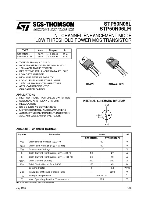
STP50N06L STP50N06LFIN -CHANNEL ENHANCEMENT MODELOW THRESHOLD POWER MOS TRANSISTORs TYPICAL R DS(on)=0.024Ωs AVALANCHE RUGGED TECHNOLOGY s 100%AVALANCHE TESTEDs REPETITIVE AVALANCHE DATA AT 100o C s LOW GATE CHARGEs HIGH CURRENT CAPABILITYs LOGIC LEVEL COMPATIBLE INPUTs 175oC OPERATING TEMPERATURE sAPPLICATION ORIENTED CHARACTERIZATIONAPPLICATIONS s HIGH CURRENT,HIGH SPEED SWITCHING s SOLENOID AND RELAY DRIVERS s REGULATORS s DC-DC &DC-AC CONVERTERS s MOTOR CONTROL,AUDIO AMPLIFIERS s AUTOMOTIVE ENVIRONMENT (INJECTION,ABS,AIR-BAG,LAMPDRIVERS,Etc.)INTERNAL SCHEMATIC DIAGRAMTYPE V DSS R DS(on)I D STP50N06L STP50N06LFI60V 60V<0.028Ω<0.028Ω50A 27A123TO-220ISOWATT220July 1993ABSOLUTE MAXIMUM RATINGSSymbol ParameterValueUnitSTP50N06LSTP50N06LFIV D S Drain-source Voltage (V GS =0)60V V DG R Drain-gate Voltage (R GS =20k Ω)60V V GS Gate-source Voltage±15V I D Drain Current (continuous)at T c =25o C 5027A I D Drain Current (continuous)at T c =100o C 3519A I D M (•)Drain Current (pulsed)200200A P tot Total Dissipation at T c =25o C 15045W Derating Factor10.3W/o C V ISO Insulation Withstand Voltage (DC)2000VT stg Storage Temperature-65to 175o C T jMax.Operating Junction Temperature175oC(•)Pulse width limited by safe operating area1231/10THERMAL DATATO-220ISOWATT220R thj-cas e Thermal Resistance Junction-case Max1 3.33o C/WR thj-amb R t hc-sin kT l Thermal Resistance Junction-ambient MaxThermal Resistance Case-sink TypMaximum Lead Temperature For Soldering Purpose62.50.5300o C/Wo C/Wo CAVALANCHE CHARACTERISTICSSymbol Parameter Max Value UnitI A R Avalanche Current,Repetitive or Not-Repetitive(pulse width limited by T j max,δ <1%)50AE AS Single Pulse Avalanche Energy(starting T j=25o C,I D=I AR,V D D=25V)400mJE AR Repetitive Avalanche Energy(pulse width limited by T j max,δ <1%)100mJI A R Avalanche Current,Repetitive or Not-Repetitive(T c=100o C,pulse width limited by T j max,δ <1%)35AELECTRICAL CHARACTERISTICS(T case=25o C unless otherwise specified)OFFSymbol Parameter Test Conditions Min.Typ.Max.Unit V(BR)DSS Drain-sourceBreakdown VoltageI D=250µA V G S=060VI DS S Zero Gate VoltageDrain Current(V GS=0)V DS=Max RatingV DS=Max Rating x0.8T c=125o C2501000µAµAI G SS Gate-body LeakageCurrent(V D S=0)V GS=±15V±100nA ON(∗)Symbol Parameter Test Conditions Min.Typ.Max.Unit V G S(th)Gate Threshold Voltage V DS=V GS I D=250µA1 1.6 2.5VR DS(on)Static Drain-source OnResistance V GS=5V I D=25AV GS=5V I D=25A T c=100o C0.0240.0280.056ΩΩI D(on)On State Drain Current V DS>I D(on)x R D S(on)maxV GS=10V50A DYNAMICSymbol Parameter Test Conditions Min.Typ.Max.Unitg fs(∗)ForwardTransconductanceV DS>I D(on)x R D S(on)max I D=25A1731SC iss C oss C rss Input CapacitanceOutput CapacitanceReverse TransferCapacitanceV DS=25V f=1MHz V G S=020006601602600900220pFpFpFSTP50N06L/FI 2/10ELECTRICAL CHARACTERISTICS(continued)SWITCHING ONSymbol Parameter Test Conditions Min.Typ.Max.Unitt d(on) t r Turn-on TimeRise TimeV DD=25V I D=25AR G=50 ΩV GS=5V(see test circuit,figure3)95550140800nsns(di/dt)on Turn-on Current Slope V DD=40V I D=50AR G=50 ΩV GS=5V(see test circuit,figure5)100A/µsQ g Q gs Q gd Total Gate ChargeGate-Source ChargeGate-Drain ChargeV DD=80V I D=50A V GS=5V42112560nCnCnCSWITCHING OFFSymbol Parameter Test Conditions Min.Typ.Max.Unitt r(Vof f) t ft c Off-voltage Rise TimeFall TimeCross-over TimeV DD=40V I D=50AR G=50 ΩV GS=5V(see test circuit,figure5)145215380210310550nsnsnsSOURCE DRAIN DIODESymbol Parameter Test Conditions Min.Typ.Max.UnitI S D I SDM(•)Source-drain CurrentSource-drain Current(pulsed)50200AAV S D(∗)Forward On Voltage I SD=50A V G S=0 1.6Vt rr Q rr I RRM Reverse RecoveryTimeReverse RecoveryChargeReverse RecoveryCurrentI SD=50A di/dt=100A/µsV DD=30V T j=150o C(see test circuit,figure5)1100.275nsµCA(∗)Pulsed:Pulse duration=300µs,duty cycle1.5%(•)Pulse width limited by safe operating areaSafe Operating Areas For TO-220Safe Operating Areas For ISOWATT220STP50N06L/FI3/10Thermal Impedeance For TO-220 Derating Curve For TO-220 Output Characteristics Thermal Impedance For ISOWATT220 Derating Curve For ISOWATT220 Transfer CharacteristicsSTP50N06L/FI 4/10STP50N06L/FI Transconductance Static Drain-source On ResistanceGate Charge vs Gate-source Voltage Capacitance VariationsNormalized Gate Threshold Voltage vsNormalized On Resistance vs Temperature Temperature5/10STP50N06L/FITurn-on Current Slope Turn-off Drain-source Voltage SlopeCross-over Time Switching Safe Operating AreaAccidental Overload Area Source-drain Diode Forward Characteristics 6/10Fig.2:Unclamped Inductive WaveformsFig.3:Switching Times Test Circuits For Resistive LoadFig.4:Gate Charge Test CircuitFig.5:Test Circuit For Inductive Load Switching And Diode Reverse Recovery TimeFig.1:Unclamped Inductive Load Test CircuitsSTP50N06L/FI7/10DIM.mminch MIN.TYP.MAX.MIN.TYP.MAX.A 4.40 4.600.1730.181C 1.23 1.320.0480.051D 2.402.720.0940.107D1 1.270.050E 0.490.700.0190.027F 0.610.880.0240.034F1 1.14 1.700.0440.067F2 1.14 1.700.0440.067G 4.95 5.150.1940.203G1 2.4 2.70.0940.106H210.010.400.3930.409L216.40.645L413.014.00.5110.551L5 2.65 2.950.1040.116L615.2515.750.6000.620L7 6.2 6.60.2440.260L9 3.5 3.930.1370.154DIA.3.75 3.850.1470.151L6ACDED 1FGL7L2Dia.F 1L5L4H 2L9F 2G 1TO-220MECHANICAL DATAP011CSTP50N06L/FI8/10DIM.mm inch MIN.TYP.MAX.MIN.TYP.MAX.A 4.4 4.60.1730.181B 2.5 2.70.0980.106D 2.5 2.750.0980.108E 0.40.70.0150.027F 0.7510.0300.039F1 1.15 1.70.0450.067F2 1.15 1.70.0450.067G 4.95 5.20.1950.204G1 2.4 2.70.0940.106H 1010.40.3930.409L2160.630L328.630.6 1.126 1.204L49.810.60.3850.417L615.916.40.6260.645L799.30.3540.366Ø3 3.20.1180.126L2ABDEHGL6ØFL3G 1123F 2F 1L7L4ISOWATT220MECHANICAL DATAP011GSTP50N06L/FI9/10STP50N06L/FIInformation furnished is believed to be accurate and reliable.However,SGS-THOMSON Microelectronics assumes no responsability for the consequences of use of such information nor for any infringement of patents or other rights of third parties which may results from its use.No license is granted by implication or otherwise under any patent or patent rights of SGS-THOMSON Microelectronics.Specificationsmentioned in this publication are subject to change without notice.This publication supersedes and replaces all information previously supplied.SGS-THOMSON Microelectronics products are not authorized for use as critical components in life support devices or systems without express written approval of SGS-THOMSON Microelectonics.©1994SGS-THOMSON Microelectronics-All Rights ReservedSGS-THOMSON Microelectronics GROUP OF COMPANIESAustralia-Brazil-France-Germany-Hong Kong-Italy-Japan-Korea-Malaysia-Malta-Morocco-The Netherlands-Singapore-Spain-Sweden-Switzerland-Taiwan-Thailand-United Kingdom-U.S.A10/10。
IPD05N03LA中文资料
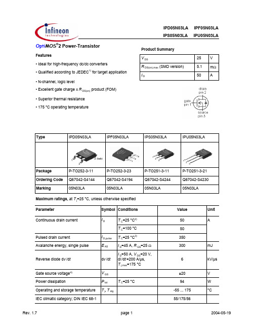
Package Ordering Code MarkingP-TO252-3-11Q67042-S414405N03LAP-TO252-3-11P-TO252-3-23P-TO251-3-11P-TO251-3-21 P-TO252-3-23Q67042-S05N03LAIPS05N03LA IPU05N03LAParameterSymbol ConditionsUnitmin.typ.max.Thermal characteristicsThermal resistance, junction - case R thJC -- 1.6K/WSMD version, device on PCBR thJAminimal footprint --756 cm 2 cooling area 5)--50Electrical characteristics, at T j =25 °C, unless otherwise specified Static characteristicsDrain-source breakdown voltage V (BR)DSS V GS =0 V, I D =1 mA 25--VGate threshold voltage V GS(th)V DS =V GS , I D =50 µA 1.2 1.62Zero gate voltage drain currentI DSSV DS =25 V, V GS =0 V, T j =25 °C-0.11µA V DS =25 V, V GS =0 V, T j =125 °C-10100Gate-source leakage current I GSS V GS =20 V, V DS =0 V -10100nA Drain-source on-state resistanceR DS(on)V GS =4.5 V, I D =30 A - 6.98.6m ΩV GS =4.5 V, I D =30 A, SMD version - 6.78.4V GS =10 V, I D =30 A - 4.4 5.3V GS =10 V, I D =30 A, SMD version- 4.2 5.1Gate resistance R G -1-ΩTransconductanceg fs|V DS |>2|I D |R DS(on)max , I D =30 A3162-S 5)Device on 40 mm x 40 mm x 1.5 mm epoxy PCB FR4 with 6 cm 2(one layer, 70 µm thick) copper area for drain Values 2)Current is limited by bondwire; with an R thJC =1.6 K/W the chip is able to carry 106 A.3)See figure 34) T j,max =150 °C and duty cycle D <0.25 for V GS <-5 V1)J-STD20 and JESD22IPS05N03LA IPU05N03LA Parameter Symbol Conditions Unitmin.typ.max. Dynamic characteristicsInput capacitance C iss-24133110pF Output capacitance C oss-9211225 Reverse transfer capacitance C rss-112167Turn-on delay time t d(on)-1015ns Rise time t r-7.812Turn-off delay time t d(off)-3138Fall time t f- 4.8 6.0Gate Charge Characteristics6)Gate to source charge Q gs-7.610nC Gate charge at threshold Q g(th)- 3.9 5.0Gate to drain charge Q gd- 5.27.8 Switching charge Q sw-9.013Gate charge total Q g-1925Gate plateau voltage V plateau- 3.2-VGate charge total, sync. FET Q g(sync)V DS=0.1 V,V GS=0 to 5 V-1722nCOutput charge Q oss V DD=15 V, V GS=0 V-2027 Reverse DiodeDiode continous forward current I S--50A Diode pulse current I S,pulse--350Diode forward voltage V SD V GS=0 V, I F=50 A,T j=25 °C-0.91 1.2VReverse recovery charge Q rr V R=15 V, I F=I S,d i F/d t=400 A/µs--10nC6) See figure 16 for gate charge parameter definition T C=25 °CValuesV GS=0 V, V DS=15 V,f=1 MHzV DD=15 V, V GS=10 V,I D=25 A, R G=2.7 ΩV DD=15 V, I D=25 A,V GS=0 to 5 V1 Power dissipation5 Typ. output characteristics9 Drain-source on-state resistance13 Avalanche characteristicsIPS05N03LA IPU05N03LA Package OutlineP-TO252-3-11: OutlineFootprint:Packaging:IPS05N03LA IPU05N03LA Package OutlineP-TO252-3-23: OutlineFootprint:IPS05N03LA IPU05N03LA Package OutlineP-TO251-3-11: OutlineP-TO251-3-21: Outline元器件交易网IPD05N03LA IPF05N03LAIPS05N03LA IPU05N03LA Published byInfineon Technologies AGBereich KommunikationSt.-Martin-Straße 53D-81541 München© Infineon Technologies AG 1999All Rights Reserved.Attention please!The information herein is given to describe certain components and shall not be considered aswarranted characteristics.Terms of delivery and rights to technical change reserved.We hereby disclaim any and all warranties, including but not limited to warranties of non-infringement,regarding circuits, descriptions and charts stated herein.Infineon Technologies is an approved CECC manufacturer.InformationFor further information on technology, delivery terms and conditions and prices, please contact yournearest Infineon Technologies office in Germany or our Infineon Technologies representatives worldwide(see address list).WarningsDue to technical requirements, components may contain dangerous substances.For information on the types in question, please contact your nearest Infineon Technologies office.Infineon Technologies' components may only be used in life-support devices or systems with theexpressed written approval of Infineon Technologies if a failure of such components can reasonablybe expected to cause the failure of that life-support device or system, or to affect the safety oreffectiveness of that device or system. Life support devices or systems are intended to be implantedin the human body, or to support and/or maintain and sustain and/or protect human life. If they fail,it is reasonable to assume that the health of the user or other persons may be endangered.Rev. 1.7page 112004-05-19。
IPS-MOSFET 功率场效应管系列产品目录
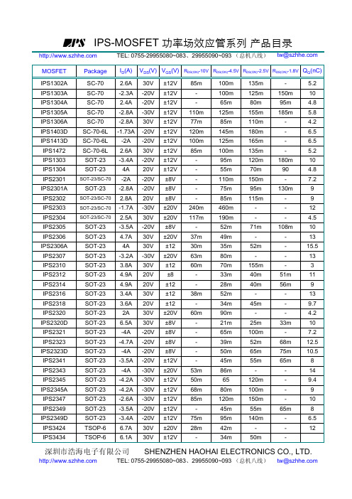
IPS-MOSFET 功率场效应管系列 产品目录
TEL: 0755-29955080~083、29955090~093 (总机八线) tw@
MOSFET
Package
ID(A) VDS(V) VGS(V) RDS(ON)-10V RDS(ON)-4.5V RDS(ON)-2.5V RDS(ON)-1.8V QG(nC)
65 80m 120m 45m 95m 42m 34m
135m 125m 80m 155m 110m 180m 165m 135m 120m 70m 150m 95m 115m
71m 52m 155m 40m 40m 45m 25m 100m 52m 65m 55m 120m 100m 150m 55m 140m 50m
-
6.5
-
12
-
深圳市浩海电子有限公司 SHENZHEN HAOHAI ELECTRONICS CO., LTD.
TEL: 0755-29955080~083、29955090~093 (总机八线) tw@
IPS-MOSFET 功率场效应管系列 产品目录
TEL: 0755-29955080~083、29955090~093 (总机八线) tw@
IPS-MOSFET 功率场效应管系列 产品目录
TEL: 0755-29955080~083、29955090~093 (总机八线) tw@
SOP-8
5.7A 40V ±20V 36m
59m
-
-
9
IPS4942
SOP-8
7A 40V ±20V 23m
33m
-
-
欧姆龙RFID
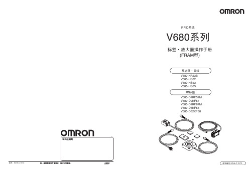
RFID㋏㒳
V680㋏߫
ᷛㅒgᬒ఼᪡ݠ (FRAMൟ)
ᬒ఼g㒓 V680-HA63B V680-HS52 V680-HS63 V680-HS65
IDᷛㅒ V680-D2KF52M V680-D2KF67 V680-D2KF67M V680-D8KF68 V680-D32KF68
Undertegnede Omron erklærer herved, at følgende den RFID System, V680-HS52 Serie, V680-HS63 Serie, V680-HS65 Serie, 680-HA63B Serie overholder de væsentlige krav og øvrige relevante krav i direktiv 1999/5/EF.
RFID 系统
2
操作手册
前言
前言 ⑥请务必遵守各项使用事项和使用禁止事项,避免发生不正确使用以及由此对客户本身及第三者造成的损
害。
4.设计·规格的变更
本产品目录中记载的各项产品、附属品的设计·规格,由于各种原因,可能会根据需要进行变更,购买时请 与销售网点的人员确认实际的设计·规格。
5.服务范围
本公司产品价格中不包含技术人员派遣等服务费用。 如客户需要提供相关技术服务,可与销售网点的人员联系。
2.责任免除
①在任何情况下,对包括因本公司产品引起的特别损失、间接损失在内的一切损失本公司均不承责任。 ②使用可编程设备时,非因本公司人员进行的编程引起的全部后果,本公司不承担任何责任。
3.适合用途、条件
①本产品并不是出于维护安全目而设计的用于直接或间接探测人类的存在的产品。相关用途请使用本公司传 感器样本中记载的安全传感器。
士兰微电子 SVD50N06T D M MJ 说明书

50A、60V N沟道增强型场效应管描述SVD50N06T/D/M/MJ N沟道增强型高压功率MOS场效应晶体管采用士兰微电子新型平面低压VDMOS 工艺技术制造。
先进的工艺及原胞结构使得该产品具有较低的导通电阻、优越的开关性能及很高的雪崩击穿耐量。
该产品可广泛应用于电子镇流器,低功率开关电源。
特点♦50A,60V,R DS(on)(典型值)=18mΩ@V GS=10V♦低栅极电荷量♦低反向传输电容♦开关速度快♦提升了dv/dt 能力命名规则士兰VDMOS产品标识额定电流标识,采用1-2位数字;例如:4 代表 4A,10 代表 10A, 08 代表 0.8A额定耐压值,采用2位数字例如:60表示600V,65表示650V封装外形标识例如:T:TO-220; D:TO-252;M:TO-251D; MJ:TO-251JS V D X N E X X X沟道极性标识,N代表N 沟道特殊功能、规格标识,通常省略例如:E 表示内置了ESD保护结构产品规格分类产 品 名 称 封装形式 打印名称 环保等级 包 装 SVD50N06T TO-220-3L SVD50N06T 无铅料管SVD50N06D TO-252-2L SVD50N06D 无卤料管SVD50N06DTR TO-252-2L SVD50N06D 无卤编带SVD50N06M TO-251D-3L SVD50N06M 无卤料管SVD50N06MJ TO-251J-3L SVD50N06MJ 无卤料管极限参数(除非特殊说明,TC=25°C)参数名称符号参数范围单位SVD50N60T SVD50N60D/M SVD50N60MJ漏源电压V DS60 V 栅源电压V GS±20 V漏极电流T C=25°CI D50A T C=100°C 31.62漏极脉冲电流I DM200 A耗散功率(T C=25°C)- 大于25°C每摄氏度减少P D110 72 83 W0.88 0.58 0.66 W/°C单脉冲雪崩能量(注1)E AS272 mJ 工作结温范围T J-55~+150 °C 贮存温度范围T stg-55~+150 °C热阻特性参数名称符号参数范围单位SVD50N60T SVD50N60D/M SVD50N60MJ芯片对管壳热阻RθJC 1.14 1.74 1.51 °C/W 芯片对环境的热阻RθJA62.5 62.0 62.0 °C/W电性参数(除非特殊说明,TC=25°C)参数符号测试条件最小值典型值最大值单位漏源击穿电压B VDSS V GS=0V,I D=250µA 60 -- -- V 漏源漏电流I DSS V DS=60V,V GS=0V -- -- 1.0 µA 栅源漏电流I GSS V GS=±20V, V DS=0V -- -- ±100 nA 栅极开启电压V GS(th)V GS=V DS,I D=250µA 2.0 -- 4.0 V 导通电阻R DS(on)V GS=10V,I D=25A -- 18 23 mΩ输入电容C issV DS=25V,V GS=0V,f=1.0MHz -- 1375.8 --pF输出电容C oss-- 393.2 -- 反向传输电容C rss-- 102.6 --开启延迟时间t d(on)V DD=30V,I D=50A,R GS=25Ω-- 21.67 --ns开启上升时间t r-- 86.67 -- 关断延迟时间t d(off)-- 32.33 -- 关断下降时间t f -- 93 --栅极电荷量Q gV DS=48V,I D=50A,V GS=10V -- 43.25 --nC栅极-源极电荷量Q gs-- 8.11 --栅极-漏极电荷量Q gd-- 23.76 --栅极电阻R G f=1MHz开漏,晶振电压:20mV -- 2.2 -- Ω源-漏二极管特性参数参 数 符 号 测试条件 最小值 典型值 最大值 单位源极电流I S MOS管中源极、漏极构成的反偏P-N结-- -- 50A源极脉冲电流I SM-- -- 200源-漏二极管压降V SD I S=50A,V GS=0V -- -- 1.5 V反向恢复时间T rr I S=50A,V GS=0VdI F/dt=100A/µs(注2)-- 67.2 -- ns反向恢复电荷Q rr-- 0.2 -- nC 注:1. L=0.1mH,I AS=53A,V DD=35V,R G=20Ω,开始温度T J=25°C;2. 脉冲测试:脉冲宽度≤300μs,占空比≤2%;3. 基本上不受工作温度的影响。
SM-2007 中文说明书[1]
![SM-2007 中文说明书[1]](https://img.taocdn.com/s3/m/01c63008f12d2af90242e63a.png)
金赛讯(天津)电子技术有限公司SM-2007数字场强仪使用手册频率测量范围:5-870MHz第一次使用本产品的用户请仔细阅读本使用手册。
如有何需要,请向生产商查询。
目录一、SM-2007数字场强仪概述 (3)二、面板功能 (4)三、详细操作指南 (6)1、开机 (6)2、频道测量功能 (7)3、斜率测量功能 (9)4、频道极限扫描功能 (10)5、频谱扫描功能 (13)6、载噪比测量功能 (14)7、干线电压测量功能 (14)8、仪器基础参数设置功能 (15)四、仪器供电电源 (25)五、技术资料 (26)一、SM-2007数字场强仪概述该产品是我公司最新研发的用于有线电视数字网改造的测量仪器。
其主要功能为测量QAM数字信号及模拟信号。
可测量项目包括:平均功率测量,MER测量,BER测量,星座图显示,频道测量,斜率测量,频道极限扫描测量,频谱扫描,载噪比测量,干线电压测量等功能。
根据使用场合的不同作相对应的选择。
内部处理芯片采用目前国际上最先进的测试仪器专用微处理器,具有功能全、处理速度快、静态耗电量极低、体积小和可靠性高等特点,外围电路根据相应功能使用专用集成块设计。
外观采取人体力学原理,可单手握紧并操作。
二、面板功能仪器简图图1-1 仪器面板说明见图1-1(1) 射频输入口(RF INPUT):此接头是可更换的,根据用户需要可更换成BNC型或F型。
(2) LCD图形显示器:根据所选择的功能显示所测量的各种参数,带有LED背景光源,而显示对比度由仪器根据环境自动调节。
(3) 功能软键:由F1 -- F4四键组成,随LCD显示界面内容不同而具有不同的功能。
(4) 导向键:由上下左右箭头组成,方便您选择相应的选项。
(5) 数字键:由0-9十个数字和[•]、[+/−]组成,方便完成各项数据的输入。
在主界面下,数字键功能如下:1:频道测量2:斜率测量3:频道极限扫描测量4:频谱扫描5:载噪比测量6:干线电压测量7:仪器基础参数设置(6) 电源开关键(7) 确认键(ENTER)(8) 删除键(C/S)(9) 频道极限扫描测量键(10) 参数设置键(11) 充电插孔(12) 充电指示灯三、详细操作指南1、开机按动电源开关键[POWER],开机显示公司名称、仪器型号及出厂序号,随后自动进入仪器主界面,如图2-1所示。
50N06规格书
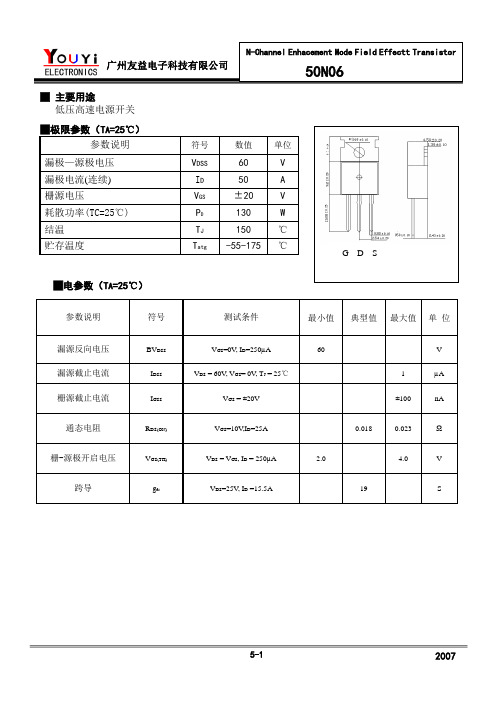
VDS=VGS,ID= 250µA
2.0
4.0
V
跨导
gfs
VDS=25V, ID=15.5A
19
S
动态特性
参数说明
符号
测试条件
最小值
典型值
最大值
单 位
输入电容
Ciss
VGS= 0V VDS=25V
f = 1.0MHz
880
1140
pF
输出电容
Coss
430
560
反向传输电容
Crss
110
参数说明
符号
测试条件
最小值
典型值
最大值
单 位
漏源反向电压
BVDSS
VGS=0V,ID=250µA
60
V
漏源截止电流
IDSS
VDS= 60V, VGS= 0V,TJ=25℃
1
µA
栅源截止电流
IGSS
VGS= ±20V
±100
nA
通态电阻
RDS(ON)
VGS=1源极开启电压
140
栅极电荷
Qg
ID=50AVDS=48V
VGS= 10V
39
45
nC
栅源电荷
Qgs
9.5
栅漏电荷
Qgd
13
开关特性
参数说明
符号
测试条件
最小值
典型值
最大值
单 位
延迟时间(开启)
td(ON)
ID=25A
VDD= 30V
RG=50Ω
60
130
ns
上升时间
trise
185
380
FAIRCHILD RFG50N06, RFP50N06, RF1S50N06SM 说明书
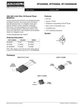
Features
• 50A, 60V • rDS(ON) = 0.022Ω • Temperature Compensating PSPICE® Model • Peak Current vs Pulse Width Curve • UIS Rating Curve • 175oC Operating Temperature
Packaging
JEDEC STYLE TO-247
SOURCE DRAIN GATE DRAIN (BOTTOM SIDE METAL) DRAIN (FLANGE)
JEDEC TO-220AB
SOURCE DRAIN GATE
JEDEC TO-263AB
GATE SOURCE
DRAIN (FLANGE)
oC/W oC/W oC/W
Drain to Source Breakdown Voltage Gate to Source Threshold Voltage Zero Gate Voltage Drain Current
Gate to Source Leakage Current Drain to Source On Resistance Turn-On Time Turn-On Delay Time Rise Time Turn-Off Delay Time Fall Time Turn-Off Time Total Gate Charge Gate Charge at 10V Threshold Gate Charge Input Capacitance Output Capacitance Reverse Transfer Capacitance Thermal Resistance Junction to Case Thermal Resistance Junction to Ambient
- 1、下载文档前请自行甄别文档内容的完整性,平台不提供额外的编辑、内容补充、找答案等附加服务。
- 2、"仅部分预览"的文档,不可在线预览部分如存在完整性等问题,可反馈申请退款(可完整预览的文档不适用该条件!)。
- 3、如文档侵犯您的权益,请联系客服反馈,我们会尽快为您处理(人工客服工作时间:9:00-18:30)。
0.6 -
0.9 45 66
50 200 1.3 -
A
V ns nC
Current is limited by bondwire; with an R thJC = 1.1 K/W the chip is able to carry 104 A at 25°C. For detailed information see Application Note ANPS071E. 2) Defined by design. Not subject to production test. 3) Qualified at -5V and +20V. 4) Device on 40 mm x 40 mm x 1.5 mm epoxy PCB FR4 with 6 cm 2 (one layer, 70 µm thick) copper area for drain connection. PCB is vertical in still air.
1)
C iss C oss Crss t d(on) tr t d(off) tf V DD=27.5 V, V GS=10 V, I D=50 A, R G=7 Ω V GS=0 V, V DS=25 V, f =1 MHz
-
7800 1180 1130 30 60 45 73
8970 1770 1700 -
10-3 10-7
single pulse
10-6
10-5
10-4
10-3
10-2
10-1
100
V DS [V]
t p [s]
Rev. 1.1
page 4
2007-11-07
元器件交易网
IPD50N06S3-07
5 Typ. output characteristics I D = f(V DS); T j = 25 °C parameter: V GS
V GS [V]
T j [°C]
Rev. 1.1
page 5
2007-11-07
元器件交易网
IPD50N06S3-07
9 Typ. gate threshold voltage V GS(th) = f(T j); V GS = V DS parameter: I D
4
200
10 V 8V
6 Typ. drain-source on-state resistance R DS(on) = f(I D); T j = 25 °C parameter: V GS
20
6V 7V 8V
175 150 125 15
7.5 V
I D [A]
7V
100 75 50 25 0 0 2 4 6 8 10
元器件交易网
IPD50N06S3-07
OptiMOS®-T Power-Transistor
Product Summary V DS R DS(on),max ID 55 6.9 50 V mΩ A
Features • N-channel - Normal Level - Enhancement mode • Automotive AEC Q101 qualified • MSL1 up to 260°C peak reflow • 175°C operating temperature • Green package (RoHS compliant) • Ultra low Rds(on) • 100% Avalanche tested PG-TO252-3-11
60
40 100
P tot [W]
80 60
I D [A]
20 0 0 50 100 150 200 0 50 100 150 200
40 20 0
T C [°C]
T C [°C]
3 Safe operating area I D = f(V DS); T C = 25 °C; D = 0 parameter: t p
10 Typ. capacitances C = f(V DS); V GS = 0 V; f = 1 MHz
Ciss
104
Coss
3.5
800µA
3
Crss
V GS(th) [V]
C [pF]
80µA
2.5
103
2
1.5
1 -60 -20 20 60 100 140 180
102 0 5 10 15 20 25
V BR(DSS) [V]
900
E AS [mJ]
55
25 A
600
300
50 A
50
0 0 50 100 150 200
45 -60 -20 20 60 100 140 180
T j [°C]
T j [°C]
15 Typ. gate charge V GS = f(Q gate); I D = 50 A pulsed parameter: V DD
-
1 1 6.2
100 100 6.9 nA mΩ
Rev. 1.1
page 2
2007-11-07
元器件交易网
IPD50N06S3-07
Parameter
Symbol
Conditions min.
Values typ. max.
Unit
Dynamic characteristics2) Input capacitance Output capacitance Reverse transfer capacitance Turn-on delay time Rise time Turn-off delay time Fall time Gate Charge Characteristics2) Gate to source charge Gate to drain charge Gate charge total Gate plateau voltage Reverse Diode Diode continous forward current2) Diode pulse current2) Diode forward voltage Reverse recovery time2) Reverse recovery charge2)
IPD50N06S3-07
13 Typical avalanche Energy E AS = f(T j) parameter: I D
1500
12.5 A
14 Drain-source breakdown voltage V BR(DSS) = f(T j); I D = 1 mA
65
1200 60
8 Typ. drain-source on-state resistance R DS(on) = f(T j); I D = 50 A; V GS = 10 V
12
150
10
100
R DS(on) [mΩ ]
0 2 4 6 8 10
I D [A]
8
50
6
0
4 -60 -20 20 60 100 140 180
100
25°C 100°C 150°C
102
I AV [A]
101
175 °C 25 °C
I F [A]
10
100 0 0.2 0.4 0.6 0.8 1 1.2 1.4
1 1 10 100 1000
V SD [V]
t AV [µs]
Rev. 1.1
page 6
2007-11-07
元器件交易网
Type IPD50N06S3-07
Package PG-TO252-3-11
Marking PN0607
Maximum ratings, at T j=25 °C, unless otherwise specified Parameter Continuous drain current1) Symbol ID Conditions T C=25 °C, V GS=10 V T C=100 °C, V GS=10 V2) Pulsed drain current2) Avalanche energy, single pulse2) Avalanche current, single pulse Gate source voltage3) Power dissipation Operating and storage temperature IEC climatic category; DIN IEC 68-1 I D,pulse E AS I AS V GS P tot T j, T stg T C=25 °C T C=25 °C I D=25 A, Value 50 50 200 710 50 ±20 136 -55 ... +175 55/175/56 mJ A V W °C Unit A
Rev. 1.1
page 1
2007-11-07
元器件交易网
IPD50N06S3-07
Parameter
Symbol
Conditions min.
Values typ. max.
Unit
Thermal characteristics2) Thermal resistance, junction - case SMD version, device on PCB R thJC R thJA minimal footprint 6 cm2 cooling area4) Electrical characteristics, at T j=25 °C, unless otherwise specified Static characteristics Drain-source breakdown voltage Gate threshold voltage Zero gate voltage drain current V (BR)DSS V GS=0 V, I D= 1 mA V GS(th) I DSS V DS=V GS, I D=80 µA V DS=55 V, V GS=0 V, T j=25 °C V DS=55 V, V GS=0 V, T j=125 °C2) Gate-source leakage current Drain-source on-state resistance I GSS RDS(on) V GS=20 V, V DS=0 V V GS=10 V, I D=50 A 55 2.1 3.0 0.01 4 1 µA V 1.1 62 40 K/W
