VF5-7中文资料
Panasonic DMC-FP5 FP7 说明书

Product identifi cation markingProduct Location Digital camera BottomBattery charger BottomAbout the battery packCAUTIONBattery pack (Lithium ion battery pack)• Use the specifi ed unit to recharge the battery pack.• Do not use the battery pack with equipment other than the specifi ed unit.• Do not get dirt, sand, liquids, or other foreign matter on theterminals.• Do not touch the plug terminals (+ and –) with metal objects.• Do not disassemble, remodel, heat or throw into fi re.If any electrolyte should come into contact with your hands or clothes, wash it off thoroughly with water.If any electrolyte should come into contact with your eyes, never rub the eyes. Rinse eyes thoroughly with water, and then consult a doctor. CAUTIONDanger of explosion if battery is incorrectly replaced. Replace only with the same or equivalent type recommended by the manufacturer.Dispose of used batteries according to the manufacturer’sinstructions.• Do not heat or expose to fl ame.• Do not leave the battery(ies) in an automobile exposed to directsunlight for a long period of time with doors and windows closed. WarningRisk of fi re, explosion and burns. Do not disassemble, heat above 60°C (140°F) or incinerate.4VQT3F03 (ENG)Keep this unit as far away as possible from electromagnetic equipment (such as microwave ovens, TVs, video games etc.).• If you use this unit on top of or near a TV, the pictures and/or sound on this unit may be disrupted by electromagnetic wave radiation.• Do not use this unit near cell phones because doing so may result in noise adversely affecting the pictures and/or sound.• Recorded data may be damaged, or pictures may be distorted, by strong magnetic fi elds created by speakers or large motors.• Electromagnetic wave radiation generated by microprocessors may adversely affect this unit, disturbing the pictures and/or sound.• If this unit is adversely affected by electromagnetic equipment and stops functioning properly, turn this unit off and remove the battery or disconnect AC adaptor (DMW-AC5PP: optional). Then reinsert the battery or reconnect AC adaptor and turn this unit on.Do not use this unit near radio transmitters or high-voltage lines.• If you record near radio transmitters or high-voltage lines, therecorded pictures and/or sound may be adversely affected.6VQT3F03 (ENG)ContentsInformation for Y our Safety (2)Standard Accessories (8)Names of the Components (9)How to Use the Touch Panel (11)Charging the Battery (13)About the Built-in Memory / the Card (16)Inserting and Removing the Card (optional) / the Battery (17)Setting Date / Time (Clock Set) (18)• Changing the clock setting (18)Setting the Menu (19)Recording Sequence (20)Taking Pictures Using the Automatic Function(4: Intelligent Auto Mode) (21)• Scene Detection (22)• Tracking moving subjects and focus (AF Tracking) (22)Recording Motion Pictures (23)Playing Back Pictures ([Normal Play]) (24)Deleting Pictures (24)Reading the Owner’s Manual (PDF format) (25)Specifi cations (27)Digital Camera Accessory System (30)Digital Camera Accessory Order Form (31)Limited Warranty (ONL Y FOR U.S.A. AND PUERTO RICO) (32)7(ENG) VQT3F03Use this to select icons or Use this to see the next/previous• Depending on the item, some settings may not be displayed or2x the focusCAB Double click the “Owner’s Manual” shortcut icon onSpecifi cationsDigital Camera:Information for your safetyPower Source:DC 5.1 VPower Consumption:1.2 W (When recording) (DMC-FP7) /1.1 W (When recording) (DMC-FP5)0.7 W (When playing back) (DMC-FP7/DMC-FP5) Camera Effective pixels:16,100,000 pixels (DMC-FP7) /14,100,000 pixels (DMC-FP5)Image sensor:1/2.33˝ CCDTotal pixels:16,600,000 pixels (DMC-FP7) /14,500,000 pixels (DMC-FP5)Primary color fi lterLens:Optical 4 × zoom, f=6.3 to 25.2 mm [35 mmfi lm camera equivalent: 35 to 140 mm] / F3.5(Wide) to F5.9 (T ele)Digital zoom:Max. 4 ×Extended opticalzoom:Max. 9.0 × (DMC-FP7) / Max. 8.4 × (DMC-FP5) Focus range:Normal :50 cm (1.64 feet) to 7Macro / Intelligent auto / Motion Picture:10 cm (0.33 feet) (Wide) / 50 cm (1.64 feet)(Tele) to 7Scene mode: settings may be different tothose shown aboveShutter system:Electronic shutter + Mechanical shutterBurst recordingBurst speed:Approx. 1.7 pictures/secondNumber ofrecordable pictures:Depends on the remaining capacity of thebuilt-in memory or the card.27(ENG) VQT3F03Hi-speed burstBurst speed:Approx. 4 pictures/secondPicture size:3M (4:3), 2.5M (3:2, 1:1) or 2M (16:9) isselected as the picture size.Number ofrecordable pictures:Approx. 15 to 100Shutter speed:8 seconds to 1/1,600th of a second[Starry Sky] mode:15 seconds, 30 seconds,60 secondsExposure (AE):Auto (Program AE)Exposure compensation (1/3 EV Step, -2 EVto +2 EV)Metering mode:MultipleLCD monitor:TFT LCD 3.5˝ (16:9) (DMC-FP7) / TFT LCD3.0˝ (3:2) (DMC-FP5) (Approx. 230,000 dots)(fi eld of view ratio about 100%)Touch panelFlash:Flash range:Approx. 0.3 m (0.99 feet) to 4.9 m (16.08 feet)(Wide [,])AUTO, AUTO / Red-eye reduction, Forced ON(Forced ON / Red-eye reduction), Slow sync. /Red-eye reduction, Forced OFFMicrophone:MonauralSpeaker:MonauralRecording media:Built-in Memory (Approx. 70 MB) /SD Memory Card / SDHC Memory Card /SDXC Memory CardRecording fi le formatStill Picture:JPEG (based on “Design rule for Camera Filesystem”, based on “Exif 2.3” standard) / DPOFcorrespondingMotion pictures:“QuickTime Motion JPEG” (motion pictureswith audio)28VQT3F03 (ENG)InterfaceDigital:USB 2.0 (High Speed)Analog video /audio:NTSCAudio line output (monaural)TerminalAV OUT/DIGITAL:Dedicated jack (8 pin)Dimensions:Approx. 101.0 mm (W) × 58.9 mm (H) ×18.2 mm (D)(3.98˝ (W) × 2.32˝ (H) × 0.72˝ (D))(excluding the projection part)Mass (Weight):Approx. 147 g/0.32 lb (DMC-FP7)Approx. 141 g/0.31 Ib (DMC-FP5)(with Memory Card and battery)Approx. 130 g/0.29 lb (DMC-FP7)Approx. 124 g/0.27 Ib (DMC-FP5)(excluding Memory Card and battery) OperatingTemperature:0 °C to 40 °C (32 °F to 104 °F)Operating Humidity:10%RH to 80%RHLanguage select:[English] / [Español]Battery Charger(PanasonicDE-A91B):Information for your safetyInput: 110 V to 240 V, 50/60 Hz, 0.2 AOutput: 4.2 V, 0.43 AEquipment mobility:MovableBattery Pack(lithium-ion)(PanasonicNCA-YN101G):Information for your safetyVoltage/capacity(Minimum): 3.6 V/660 mAh29(ENG) VQT3F03THERE ARE NO EXPRESS WARRANTIES EXCEPT AS LISTED UNDER “LIMITED WARRANTY COVERAGE”.THE WARRANTOR IS NOT LIABLE FOR INCIDENTAL OR CONSEQUENTIAL DAMAGES RESULTING FROM THE USE OF THIS PRODUCT, OR ARISING OUT OF ANY BREACH OF THIS WARRANTY.(As examples, this excludes damages for lost time, travel to and from the servicer, loss of or damage to media or images, data or other memory or recorded content. The items listed are not exclusive, but for illustration only.)ALL EXPRESS AND IMPLIED WARRANTIES, INCLUDING THE WARRANTY OF MERCHANTABILITY, ARE LIMITED TO THE PERIOD OF THE LIMITED WARRANTY.Some states do not allow the exclusion or limitation of incidental or consequential damages, or limitations on how long an implied warranty lasts, so the exclusions may not apply to you.This warranty gives you specific legal rights and you may also have other rights which vary from state to state. If a problem with this product develops during or after the warranty period, you may contact your dealer or Service Center. If the problem is not handled to your satisfaction, then write to the warrantor's Consumer Affairs Department at the addresses listed for the warrantor.PARTS AND SERVICE, WHICH ARE NOT COVERED BY THIS LIMITED WARRANTY, ARE YOUR RESPONSIBILITY.34VQT3F03 (ENG)。
PHOENIX CONTACT 5孔绿色插针5-pos版商品说明书

Extract from the onlinecatalogPCV 4/ 2-G-7,62Order No.: 1804687The figure shows a 5-pos. version of the producthttp://eshop.phoenixcontact.de/phoenix/treeViewClick.do?UID=1804687Header, Nominal current: 20 A, Nom. voltage: 400 V, Pitch: 7.62 mm, Number of positions: 2, Color: green, Assembly: Solderinghttp://Please note that the data givenhere has been taken from theonline catalog. For comprehensiveinformation and data, please referto the user documentation. TheGeneral Terms and Conditions ofUse apply to Internet downloads. Technical dataDimensions / positionsPitch7.62 mmDimension a7.62 mmNumber of positions2Pin dimensions 1 x 0,8 mmHole diameter 1.3 mmTechnical dataInsulating material group IRated surge voltage (III/3) 6 kVRated surge voltage (III/2) 6 kVRated surge voltage (II/2) 6 kVRated voltage (III/2)630 VRated voltage (II/2)630 VConnection in acc. with standard EN-VDENominal current I N20 ANominal voltage U N400 VMaximum load current20 AInsulating material PAInflammability class acc. to UL 94V0Certificates / ApprovalsCertification BV, CSA, CUL, DNV, GL, GOST, LR, RS, ULCSANominal voltage U N300 VNominal current I N20 ACULNominal voltage U N300 VNominal current I N35 AULNominal voltage U N300 VNominal current I N35 AAccessoriesItem Designation DescriptionAssembly1827570BF-PC 4Mounting flange, is snapped onto the left and right of the headers,for screw connection with PC 4/...-STF-7.62Marking1051993B-STIFT Marker pen, for manual labeling of unprinted Zack strips, smear-proof and waterproof, line thickness 0.5 mm0804549SK 7,62/3,8:FORTL.ZAHLEN Marker card, printed horizontally, self-adhesive, 10-section markerstrip, 12 identical decades marked 1-10, 11-20 etc. up to 91-99,sufficient for 120 terminal blocks0805153SK 7,62/3,8:SO Marker card, special printing, self-adhesive, labeled acc. tocustomer requirements, 12 identical marker strips per card, max.25-position labeling per strip, color: white0803906SK U/3,8 WH:UNBEDRUCKT Unprinted marker cards, DIN A4 format, pitch as desired, self-adhesive, with 40 stamped marker strips, 185 mm strip length, canbe labeled with the CMS system or manually with the M-PENPlug/Adapter1600027CP-HCC 4Coding profile, Color: redAdditional productsItem Designation DescriptionGeneral1848892PC 4 HV/ 2-ST-7,62Plug component, Nominal current: 20 A, Nom. voltage: 800 V,Pitch: 7.62 mm, Number of positions: 2, Connection type: Screwconnection, Color: green1882379PC 4 HV/ 2-STF-7,62Plug component, Nominal current: 20 A, Nom. voltage: 800 V,Pitch: 7.62 mm, Number of positions: 2, Connection type: Screwconnection, Color: green1804904PC 4/ 2-ST-7,62Plug component, Nominal current: 20 A, Nom. voltage: 400 V,Pitch: 7.62 mm, Number of positions: 2, Connection type: Screwconnection, Color: green1828249PC 4/ 2-STF-7,62Plug component, Nominal current: 20 A, Nom. voltage: 400 V,Pitch: 7.62 mm, Number of positions: 2, Connection type: Screwconnection, Color: green1840191PCC 4/ 2-ST-7,62Plug component, Nominal current: 20 A, Nom. voltage: 400 V,Pitch: 7.62 mm, Number of positions: 2, Connection type: Crimpconnection, Color: greenDiagrams/DrawingsDrilling plan/solder pad geometryDimensioned drawingAddressPHOENIX CONTACT Inc., USA586 Fulling Mill Road Middletown, PA 17057,USA Phone (800) 888-7388Fax (717) 944-1625© 2010 Phoenix Contact Technical modifications reserved;。
DMN5L06VK-7;DMN5L06VAK-7;中文规格书,Datasheet资料

1
3 of 6
VGS, GATE SOURCE VOLTAGE (V) Fig. 6 Static Drain-Source On-Resistance
Packaging 3,000/Tape & Reel 10,000/Tape & Reel 3,000/Tape & Reel 10,000/Tape & Reel 3,000/Tape & Reel 10,000/Tape & Reel
1. No purposely added lead. Fully EU Directive 2002/95/EC (RoHS) & 2011/65/EU (RoHS 2) compliant. 2. See for more information about Diodes Incorporated’s definitions of Halogen- and Antimony-free, "Green" and Lead-free. 3. Halogen- and Antimony-free "Green” products are defined as those which contain <900ppm bromine, <900ppm chlorine (<1500ppm total Br + Cl) and
VGS(th)
0.49
⎯
⎯
⎯
RDS (ON)
⎯
⎯
⎯
⎯
ID(ON)
0.5
1.4
|Yfs|
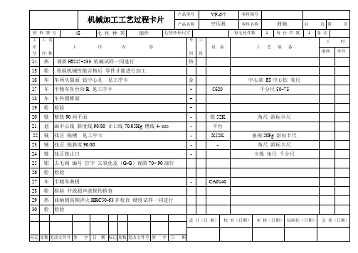
VF6-7空气压缩机曲轴加工工艺及夹具设计 机械加工工艺过程卡片
找正粗精磨曲拐
MQ8260
卡规Φ65g6 塞规80AII 百分表 尺样规
设计(日期)
校对(日期)
审核(日期)
标准化(日期)
会签(日期)
标记
处数
更改文件号
签字
日期
标记
处数
更改文件号
签字
日期
机械加工工艺过程卡片
产品型号
VF-6/7
零件图号
产品名称
空压机
零件名称
曲轴
共
页
第
页
材料牌号
45
毛 坯 种 类
锻件
车两头端面 钻中心孔 见工序卡
金
中心架 B5中心钻 卷尺
17
车
半精车各台阶R见工序卡
-
C620
千分尺50-75
18
车
车外圆锥面
-
19
检
检验
-
20
铣
精铣90两平面
-
铣52K
角尺游标卡尺
21
划
画中心线斜度线90/80止口线70.05Hg槽线4-Ø20
-
平台
22
铣
找正铣槽见工序卡
-
X52K
塞规20Fg游标卡尺
23
铣
找正铣斜度90/80
-
-
角尺游标卡尺
24
铣
找正铣止口
-
卡规角尺千分尺
25
钳
去毛刺编号打字去氧化皮(G-G)视图70 90部位
26
检
检验
27
车
半精车曲拐
-
CA6140
28
检
检验并做超声波探伤检查
29
松下VF-7F变频说明书
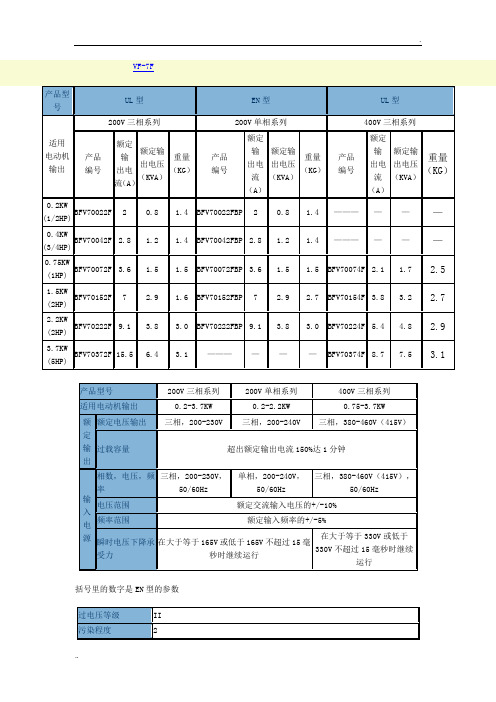
33
预设第5频率
设定第5频率
0000:0V停止,0.2-400Hz
15.00
34
预设第6频率
设定第6频率
0000:0V停止,0.2-400Hz
25.00
35
预设第7频率
设定第7频率
0000:0V停止,0.2-400Hz
35.00
36
预设第8频率
设定第8频率
0000:0V停止,0.2-400Hz
加/减速时间2,3和4
0.1-999秒(单独加速和减速时间设定)。可与多速设定连动。
多速频率设定
最多可预设(可编程)8速频率。可与加速和减速时间设定连动。
跨跃频率设定
最多可设定3个频率跨跃点(频率跨跃幅度为1-10Hz)
上限频率设定
设定为 0.5-400Hz
下限频率设定
设定为 0.5-400Hz
偏置和增益频率设定
最低80制制动动转矩直流动态制动低于设定的停止频率时工作设定制动转矩和制动时间外运行频率信号05vdc专业资料整理部集电极开路输出最大50v50ma运行信号到达信号频率检测信号输过载报警信号反转信号可选择输出信号一组接点1c输出接点容量250vdc阻抗负载05a故障报警信运行条件输出频率设定频率f1a2线速显示选择转换器输出电流a0输出电压a1旋转方向故障跳闸存贮器保护功能发挥作用时进行显示存储最后4个故障电流限制电流限制可设定为额定输出电流的1200关闭停止瞬时过电流过热sc过电流oc电压过低lv过电压ov辅助连装置跳闸au过载电子过热ol操作错误op失速防止过电流失速防止再生过电压失速防止环境温度和相对温度1010c到5010c无结冰最高相对温度的90储运温度和相对2510c到6510c最高相对湿度的95温度振动最大59米秒06g根据jisc0911安装条件最高海拔1000参数设定参数序号参数名称设置对象设定值或代码出厂设置01第一加速时间设置加速时间
惠普 Hu-57低成本模块式天气站规格表说明书

Hu-57Low-Cost Modular Weather StationSpecifications GENERALReporting Units: English/metric, all measurements user selectable Operating Power:9-12 Vdc Power Consumption:60 mA maximumCommunications:9-pin D-subminiature, 9600 bps, flow controlBattery Back-Up:9 Volt battery,lasts 30 hrs minimum Memory:32 kB Ram Operating Temperature Transducers:-40 to 60°C (-40 to 140°F)Data Acquisition Module:-3 to 43°C (25 to 110°F)The WMS-14 Modular Weather Station is a personal computer-based weather station capable of simultaneously recording windspeed, wind direction, temperature,relative humidity, barometric pressure, and rainfall. Itautomatically measures and stores outdoor weather conditions at user-selected intervals of 1 to 60 minutes for up to one month in an internal memory module.The Model WMS-14 provides asophisticated yet way-to-use system for retrieving, storing, and displaying information. Data flows to and from the weather station at speeds up to 9600 BPS using a standard ASCII terminal protocol via an RS-232serial interface. With simple numeric commands, the user can choose to either view the real time report page or view the log of historical data.Data logs are quickly transferred to a disk file for storage or for graphing and numerical analysis. A colorful VGA graphical display is readily available to view real-time data.The Model WMS-14 features a combination wind vane and three-cup anemometer with 40 feet of interconnecting cable (which may be extended to 300 feet), atemperature and relative humidity sensor with sun shield, a solid state barometric pressure sensor, and, a self-emptying rain gauge.ߜDurable Modular Designfor Easy Configuration ߜ30-Day Memory; Set andForget OperationߜStores ASCII Data withTime TagsߜReal-Time VGAGraphical Display ߜExceeds IndustryStandards forPerformance and PriceUSAMADE INWMS14 Series$1495Basic UnitHu-58HuTo Order (Specify Model No.)Model No.Price DescriptionWMS-14$1495Complete weather station with tripod mastWMS-14EPA 1735Complete weather station with high sensitivity windsensor.WMS-14D 495Data Acquisition moduleWMS-05D 450High sensitivity wind/speed direction sensorWMS-14TH 250Outdoor temperature/humidity sensor, with 25' cable WMS-14THS 90Solar radiation shield for temp/RH sensor WMS-14BP 200Barometric PressureWMS-14RF 125Rainfall collector, 25' cable WMS-14TM90Tripod mast 10'WMS-14 comes complete with outdoor temperature/humidity sensor with 25' cable, barometric pressure sensor, solar radiation shield, rain collector plus 25' cable, 10' tripod mast, data acquisition module, plus complete operator's manual.Ordering Example: WMS-14 weather station with mast ($1495) plus WMS-EC-40extension cable ($40), $1495 + 40 = $1535.AccessoriesModel No.Price Description WMS-EC-40$2040' Extension cable for wind sensor WMS-RGC-402040' Extension cable for rain sensor WMS-TC-402440' Extension cable for temperature humidity sensorWMS-14 Data Acquisition Module IncludedWINDSpeed Range:0-99.9 mph (0-160 kph)Resolution:0.1 mph Accuracy:±3% for sustained 2 sec avg.Time Constant:2 secDIRECTIONResolution:22°(16 compass points)Time Constant:2 secTEMPERATURERange:-40 to +140°F Resolution:1°F Accuracy:±2°F Update Rate:1 min. avg.Wind Chill Enable Range:-40 to +7°C (-40 to +45°F)BAROMETRIC PRESSURERange:28.25 to 30.75 in Hg Resolution:±0.01 in Hg or ±1 millibarAbsolute Accuracy:±0.05 in Hg Update Rate:1/minAltitude Offset:-0 to 10,000 feet,screwdriver adjustableHYDROMETERRange:0-100% RHAccuracy:±3% mid range, ±6% @20% & 90% RHTime Constant:5 min. avg.RAIN GAGEResolution:0.004"/0.01"/1 mmm Accuracy:5%Max. Rate:3in/hrTIMEKEEPINGFormat:4 digit, 24 hr military timeAccuracy:5 sec in 24 hrs.CANADA www.omega.ca Laval(Quebec) 1-800-TC-OMEGA UNITED KINGDOM www. Manchester, England0800-488-488GERMANY www.omega.deDeckenpfronn, Germany************FRANCEwww.omega.fr Guyancourt, France088-466-342BENELUX www.omega.nl Amstelveen, NL 0800-099-33-44UNITED STATES 1-800-TC-OMEGA Stamford, CT.CZECH REPUBLIC www.omegaeng.cz Karviná, Czech Republic596-311-899TemperatureCalibrators, Connectors, General Test and MeasurementInstruments, Glass Bulb Thermometers, Handheld Instruments for Temperature Measurement, Ice Point References,Indicating Labels, Crayons, Cements and Lacquers, Infrared Temperature Measurement Instruments, Recorders Relative Humidity Measurement Instruments, RTD Probes, Elements and Assemblies, Temperature & Process Meters, Timers and Counters, Temperature and Process Controllers and Power Switching Devices, Thermistor Elements, Probes andAssemblies,Thermocouples Thermowells and Head and Well Assemblies, Transmitters, WirePressure, Strain and ForceDisplacement Transducers, Dynamic Measurement Force Sensors, Instrumentation for Pressure and Strain Measurements, Load Cells, Pressure Gauges, PressureReference Section, Pressure Switches, Pressure Transducers, Proximity Transducers, Regulators,Strain Gages, Torque Transducers, ValvespH and ConductivityConductivity Instrumentation, Dissolved OxygenHeatersBand Heaters, Cartridge Heaters, Circulation Heaters, Comfort Heaters, Controllers, Meters and SwitchingDevices, Flexible Heaters, General Test and Measurement Instruments, Heater Hook-up Wire, Heating Cable Flow and LevelAir Velocity Indicators, Doppler Flowmeters, LevelMeasurement, Magnetic Flowmeters, Mass Flowmeters,Pitot Tubes, Pumps, Rotameters, Turbine and Paddle Wheel Flowmeters, Ultrasonic Flowmeters, Valves, Variable Area Flowmeters, Vortex Shedding FlowmetersData AcquisitionAuto-Dialers and Alarm Monitoring Systems, Communication Products and Converters, Data Acquisition and Analysis Software, Data LoggersPlug-in Cards, Signal Conditioners, USB, RS232, RS485 and Parallel Port Data Acquisition Systems, Wireless Transmitters and Receivers。
东芝VFP7系列变频器中文说明书

务请接好地线,否则会在故障或漏电时引发触电或火灾事故。
2
TOSHIBA
危险
禁止接触
禁止
请勿接触变频调速器的散热风扇或放电电阻器,否则会引起高温和烫伤。
应使用与电源电压及三相感应电机的规格相匹配的变频调速器,否则不仅电机无法正确运 转,而且可能会导致变频调速器或电机过热或烧毁等重大事故。
东芝(中国)有限公司上海事务所
地址:上海市浦东新区银城东路 101 号 邮政编码:200120
电话:(021)-6841-5666(代表)
传真:(021)-6841-1161
东芝(中国)有限公司广州事务所
地址:广州环市东路 403 号广州国际电子大厦 1201-1202 邮政编码:510015 电话:(020)-8732-2646 传真:(020)-8732-2651
图标的意义
图标
意义 表示禁止事项(不允许做的事情)。 具体内容由图标中间或旁边的图文表示。 表示强制事项(必须做的事情)。 具体内容由图标中间或旁边的图文表示。
g 用户使用须知
用户选购的变频调速器用于一般工业用三相感应电动机的变速运转。
安全注意事项
t 在因变频调速器故障或工作错误可威胁生命或危害人体的设备(核动力控制设备、宇航设备、 交通工具用设备、各种安定设备等)中不可使用本变频调速器。如需要作特殊用途,请事先 问询本公司的经销负责人。
-对安装厂家的要求- 请注意务必把本使用说明书交到变频调速器的实际使用者手中。
株式会社 东芝
总公司 日本国东京都港区芝浦 1 丁目 1 番 1 号
邮政编码:105-0081 电话:03-3457-4880 传真:03-5444-9268
希捷PD5系列数字移动通信手持无线电说明书

PD5 SeriesDMR handheld radiosThe PD5 series from Hytera convinces with its compact design,scope of functions and high cost efficiency. With the support ofdigital and analog mobile radio, the PD5 series is your perfectcompanion for entering the professional digital mobile radio.HighlightsCompact, lightweight and easy to operateThe radios of the PD5 series are particularly ergonomic and easy to operate. With aweight of only 260 g (PD505) or 280 g (PD565), the PD5 series offers a high level ofmobility comfort.Cost-efficient with superlative voice qualityWith the combined application of the narrow-band codec and digital technologiesfor error correction, the PD5 series ensures a superlative voice quality even in loudenvironments or in peripheral areas of the radio coverage.The lithium-ion battery (1500 mAh) included in the scope of delivery achieves anoperating time of at least 16 hours (duty cycle 5-5-90). With the optionally available2000-mAh battery, it will even be 20 hours.Support of analog and digital mobile radioThe PD5 series was developed in compliance with the ETSI mobile radio standardDigital Mobile Radio (DMR). The handheld radios support the conventional DMRmode and can also be operated in manual mode. On top of that, the radios supportHytera XPT radio systems. That makes the terminals of the PD5 series the ideal com-panion for the move to digital mobile radio.Pseudo trunked radiotimeslots of a frequency. As a result, the radios can utilize both timeslots in DMOand RMO mode in the conventional DMR operation. This guarantees an efficientfrequency utilization.Additional Functions (selection)One-touch functions with which preprogrammed text messages, voice calls andsupplementary functions can be called up quicklySupport of several expanded analog signal modes, including HDC1200, 2-toneand 5-tone, for an improved integration in existing analog radio fleetsHytera basic encryption (40 bit) in digital operationLeasing functionVersatile voice calls: Individual call, group call, broadcast call, data call,emergency callDMRA data serviceWireless radio activation/deactivation (enable/disable),Priority interruptand remote monitor function (optional)P D 565Lithium-ion battery (1500 mAh) BL1502Quick charger CH10A07Hand strap RO03Belt clip BC12Switching power adapt-er for charger PS1018Earphone ESM12Remote speaker Vehicle power adapter CHV09Carrying case (nylon) NCN0116-unit charger MCA08Lithium-ion battery (2000 mAh) BL2010Hytera Mobilfunk GmbHAddress: Fritz-Hahne-Straße 7, 31848 Bad Münder, Germany Tel.: + 49 (0)5042 / 998-0 Fax: + 49 (0)5042 / 998-105 E-mail:**************|Your Hytera partner:Further information can be found at: Contact us if you are interested in sales, distribution or application partnership: **************SGS Certificate DE11/81829313Hytera Mobilfunk GmbH reserves the right to modify the product design and the specifications. In case of a printing error, Hytera Mobilfunk GmbH does not accept any liability. All specifications are subject to change without notice.Encryption features are optional and have to be configured separately; they are also subject to German and European export regulations.are registered trademarks of Hytera Co. Ltd. ACCESSNET®and all derivatives are protected trademarks of Hytera Mobilfunk GmbH. © 2016 Hytera Mobilfunk GmbH. All rights reserved.Ref. no.:90PD5Series_Fly_ENG_v04All technical information was determined at the factory and in accordance with the corresponding standards. Subject to change on the basis of continuous development.Technical Data。
非线性光学晶体
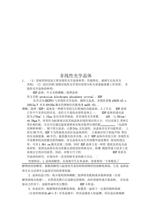
非线性光学晶体1、(1)查阅资料综述主要非线性光学晶体种类、性能特征、液相生长技术及其制;(2)试以倍频/混频非线性光学效应原理分析光参量振荡器工作原理。
非线性光学晶体的种类:KDP晶体:中文名称磷酸二氢钾晶体英文名称 potassium dihydrogen phosphate crystal ,KDP化学式为KH2PO4勺非线性光学晶体,属四方晶系。
非线性系数d3630.63 x 10012m/V 对0.69430m激光倍频相位匹配角B mm50.451 。
磷酸二氢钾(KDP)晶体是一种最早受到人们重视的功能晶体,人工生长KDP晶体已有半个多世纪的历史,是经久不衰的水溶性晶体之一。
KDP晶体的透光波段为178nm^ 1.45um,是负光性单轴晶,其非线性光学系数d36 (1.064um)=0.39pm/V,常常作为标准来比较其他晶体非线性效应的大小,可以实现I 类和U 类位相匹配,并且可以通过温度调谐来实现非临界位相匹配__________ (包括四倍频和和频)。
属于四方晶系,点群D4h,无色透明。
该晶体具有多功能性质。
上世纪50年代,KDP乍为性能优良的压电晶体材料,主要被应用于制造声纳和民用压电换能器。
60年代,随着激光技术出现,由于 KDP晶体具有较大的非线性光学系数和较高的激光损伤阈值,而且晶体从近红外到紫外波段都有很高的透过率,可对1.064 ym激光实现二倍频,同时 KDP晶体又是一种性能优良的电光晶体材料。
使得该晶体在高功率激光系统受控热核反应、核爆模拟等重大技术上更显现出它的应用前景,因此,对特大尺寸的KDP优质光学晶体的研究,在国内外一直受到研究者的极大关注。
J性能特征:1.晶体溶解度:从溶液中生长单晶体,很重要的一个参数是了解物质的溶解度。
根据溶解度与温度的关系绘制得到物质的溶解度曲线,它是选择晶体生长方法和生长温度区间的重要依据。
2.晶体结晶习性:取少量纯固体磷酸二氢钾将其配制成未饱和溶液(以溶解度曲线为依据),自然蒸发数日后逐渐达到饱和,此时溶液形成少量晶核,在结晶驱动力作用下,逐渐形成外形完整的KDP小籽晶。
STEP7V55中文版简介5%d6%d0%ce%c4%b0%e6%bc%f2%bd%e9

SIMATIC编程软件件用于SIMATIC S7 / M7 / C7的STEP 7 V5.5编程软安装与使用注意事项该注意事项中包含的信息相对于其它文档来说是最新的。
请仔细阅读,此文本中包含了有关STEP 7 V5.5的安装与使用信息。
对该版本的重要修订以斜体显示,并标有注释“从该版本开始新增的内容”。
请注意,对于A4格式,所要打印文件的左右边距都设置成25 mm。
目录安装注意事项1发货清单2硬件要求3软件要求3.1运行环境3.2需要的存储空间3.3与其它软件产品的兼容性3.3.1Rational ClearCase配置管理工具3.3.2使用其它软件产品时的网络设置3.4在线文档4安装4.1安装STEP 7 V5.54.2升级旧版STEP 74.3STEP 7 V5.5许可证密钥4.4删除STEP 7 V5.54.5安装时的其它注意事项4.5.1使用滚轮鼠标4.5.2使用PC/PG通信卡时的注意事项使用注意事项(版本注释)5新版软件的新特性和所作的修改6组态和操作软件时的注意事项6.1STEP 7如何满足IEC标准6.2常规注意事项6.3使用网络驱动器6.4多用户操作6.5多重项目6.6交换不同版本的STEP 76.7库文件和实例项目6.8SIMATIC管理器6.9使用符号名6.10硬件配置(中央机架)6.11硬件配置(PROFIBUS DP)6.12硬件配置(PROFINET IO)6.13冗余I/O:通道间隔冗余6.14硬件诊断6.15MPI / PROFIBUS网络设置6.16SIMATIC M76.17梯形图、功能块图、语句表和参考数据6.18翻译文本6.19管理多语言文本6.20将S5程序转换成S7程序6.21将TI程序转换成S7程序6.22容错系统6.23使用外文字符集时的注意事项6.24使用SIMATIC Logon的注意事项6.25命令接口6.26TCI –工具调用接口6.27MS Windows 7操作系统的特性7文档注意事项8使用STEP 7中文版时的重要特性安装注意事装注意事项项以前请务本注意事项中包含您在安装STEP 7 V5.5时所需的重要信息,在安装该软件以前以前必详细阅读该注意事项。
Fiery XF 7 说明书

Fiery XF 7© 2018 Electronics For Imaging, Inc. 此产品的《法律声明》适用于本出版物中的所有信息。
2018 年 12 月 19 日目录Fiery Command WorkStation 概述 (11)Job Center (11)用于管理队列中作业的命令 (12)工具栏图标 (12)作业搜索 (13)Job Editor (14)Server Manager (14)系统维护 (14)配置 Command WorkStation (16)登录到多个 Fiery 服务器 (16)移除 Fiery server (16)添加更多打印机 (16)配置网络打印机 (17)配置通过 USB 连接的打印机 (17)配置打印到文件输出 (18)承印材料和工作流程 (18)配置承印材料 (19)配置工作流程 (19)配置用户帐户 (23)登录到 Command WorkStation (24)注销 Command WorkStation (24)导入作业 (25)直接导入作业到 Job Center (25)在导入时自动处理作业 (26)热文件夹和虚拟打印机 (26)配置热文件夹 (27)配置虚拟打印机 (27)Fiery XF Universal Driver (28)安装 Universal Driver (28)登录到 Universal Driver 并打印 (28)Universal Driver 设定 (29)配置打印机设定 (30)开始打印 (30)取消作业处理 (31)PostScript 和 PDF 作业 (32)切换到不同的 PDF 打印引擎 (32)EPS 作业检测 (33)为 EPS 作业检测设置时间推移或更改输入分辨率 (33)采用 RIP 自动分色 (33)设置 Command WorkStation 如何处理 in-RIP 信息 (34)页面框定义 (34)指定页面框 (35)工作色彩空间 (35)应用工作色彩空间 (35)在合成作业中套印 (36)在合成作业中模拟套印 (36)管理 PDF 作业中的非嵌入字体 (36)将多页 PDF 作业作为单页加载 (36)编辑作业 (38)旋转作业 (38)翻转作业 (38)缩放作业 (38)对齐印张上的作业 (39)裁切作业 (39)撤销作业编辑 (40)将作业设定另存为工作流程 (40)可视辅助工具 (40)更改测量单位 (41)放大 (41)打开对齐 (42)设置标尺坐标 (42)使用参考线 (42)显示可视辅助工具 (42)作业标签 (43)创建或编辑作业标签 (43)打印作业标签 (43)调整作业标签的大小 (44)控制栏 (45)选择控制栏 (45)创建动态楔入 (45)跨两行打印作业标签 (46)嵌入 (47)嵌入所有作业 (47)强制嵌入以打印 (48)嵌入所选作业 (48)添加、移除或删除套叠式作业 (48)克隆套叠式作业 (49)重命名嵌入 (49)排列套叠式作业 (49)在印张上将所有套叠式作业对齐 (49)编辑套叠式作业 (50)缩放套叠式作业 (50)在印张的固定位置锁定套叠式作业 (50)添加套叠式作业周围的边距 (51)打印多页 PDF 的所选页面 (51)平铺 (52)创建平铺 (52)创建具有重叠效果的图素 (53)打印具有粘合区域的图素 (53)调整图素大小 (54)将图素边缘锁定到固定位置 (54)合并或拆分图素 (54)显示和保存平铺预览 (55)拆分图素以进行打印 (55)对平铺作业进行后期编辑 (56)步骤和重复 (57)创建步骤和重复 (57)修改步骤和重复 (58)作业合并 (59)设置自动作业合并的工作流程 (59)手动合并作业 (60)校准和生成特性档工具 (61)启动 Color Tools (61)校准打印机 (61)非 EFI 宽幅打印机的校准过程 (62)EFI 宽幅打印机的校准过程 (68)打印机优化 (75)为承印材料特性档优化进行设定 (76)选择一个 L*a*b* 优化文件。
建伍TH-F6 F7中文说明书手册

建伍TH-F6 F7中文说明书手册使用说明书TH-F6A 144/220/440MHz 调频三段机TH-F7E 144/430MHz 调频双段机熟悉本机显示屏图1. EL 对讲机设定输出功率为LOW时, 显示“L”低功率,设定输出功率为ECONOMLO LOW时, 显示“EL”超低功率 {7, 14页}2. H 高功率对讲机设定输出功率为HIGH时, 显示“H”高功率 {7, 14页}3. LSB 下边带在B波段选择下边带时, 显示LSB {34页} 4. USB 上边带在B波段选择上边带时, 显示USB {34页} 5. CW 电报码在B波段选择电报码时, 显示CW {见34页} 6. WFMN宽窄带调频选择宽带调频时, 显示“WFM” {34页} 选择标准调频时, 显示“FM” {39页} 选择窄带调频时, 显示“NFM” {39页}7. AM 调幅选择AM调幅模式时, 显示AM {34页}P 优先扫描使用优先扫描功能时, 显示“P” {25页} 8.9. FINE 细调使用细调功能时, 显示FINE {35页}10. VOX 声控发射使用声控发射功能时, 显示VOX {41页} 11. “R” 自动单工检测使用自动单工检测功能(ASC)时, 显示“R” {14 页} 12. “?” 键盘锁定选择键盘锁定功能开启ON时, 显示“?” {38页} 13. “F” 功能键功能键被按时, 显示该符号“F”发射强度指示 14. 接收场强 /15. CT 哑音频信令使用哑音频信令功能时, 显示CT {28页} 16. “T” 音频信令使用音频信令功能时, 显示“T” {13页} 17. DCS 数字哑音频使用数字哑音频功能时, 显示DCS{29页} 18. + / - /“?” 异频中继台使用异频功能时, 显示该符号 {12页} 19. R 倒频使用倒频功能时, 显示R {14页}20. 振铃提示使用振铃提示功能时, 显示。
松下VF-5变频器说明书
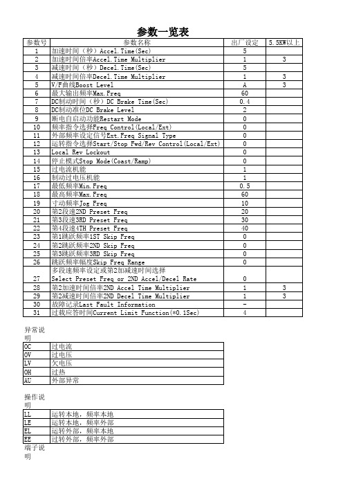
13 Local Rev Lockout
14 停止模式Stop Mode(Coast/Ramp)
15 过电流机能
16 制动过电压机能
17 最低频率Min.Freq
18 最高频率Max.Freq
19 寸动频率Jog Freq
20 第2段速2ND Preset Freq
21 第3段速3RD Preset Freq
28 第2加速时间倍率2ND Accel Time Multiplier
29 第2减速时间倍率2ND Decel Time Multiplier
30 故障记录Last Fault Information
31 过载应答时间Current Limit Function(*0.1Sec)
出厂设定 5 1 5 1 A 60 0.4 2 0 0 0 0 0 0 1 1 0.5 60 10 20 30 40 0 0 0 0
0 1 1 4
5.5KW以上 3 3 3
3 3
异ቤተ መጻሕፍቲ ባይዱ说 明 OC OV LV OH AU
过电流 过电压 欠电压 过热 外部异常
操作说 明 LL LE EL EE 端子说 明
运转本地,频率本地 运转本地,频率外部 运转外部,频率本地 过转外部,频率外部
1 +5V 2 频率信号输入 3地 4 0-5V/0-10V 5 4-20mA 6 外接频率表 7 启动 8地 9 停止 10 反转 11 地 12 寸动 13 S1 14 S2 15 S3 16 外部故障 17 地 18 复位 19 RY1 20 RY1-COM,RY2-COM 21 RY2 22 RY3常闭 23 RY3-COM 24 RY3常开 7-8, 16-17短 接 设置参 数时, 先按 LOCK, MODE选 择参数 号,DFWD改变 参数 值,SET 保存数 据, 再按一 下LOCK 返回
杰弗逊(Jefferson) 5V 10V DC 通用输出压力传感器说明书
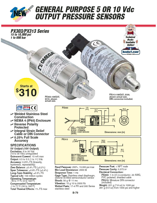
Snubbers protect sensors from fluid spikes/hammers!
1⁄4 NPT Pressure Snubbers: $10 PS-4G = Gas PS-4E = Lt Oil PS-4D = Dense Lq
PX303-100G5V, $310, shown actual size.
0 to 2000 0 to 138 PX303-2KG5V 310 PX313-2KG5V
330 DP24-E, DP25B-E, DP41-E, DPi Series
0 to 3000 0 to 207 PX303-3KG5V 310 PX313-3KG5V
330 DP24-E, DP25B-E, DP41-E, DPi Series
*(50$1< ZZZRPHJDGH 'HFNHQSIURQQ *HUPDQ\
%(1(/8; ZZZRPHJDQO
More than 100,000 Products Available!
7HPSHUDWXUH
Calibrators, Connectors, General Test and Measurement Instruments, Handheld Instruments for Temperature Measurement, Ice Point References, Indicating Labels, Crayons, Cements and Lacquers, Infrared Temperature Measurement Instruments, Recorders, Relative Humidity Measurement Instruments, PT100 Probes, PT100 Elements, Temperature & Process Meters, Timers and Counters, Temperature and Process Controllers and Power Switching Devices, Thermistor Elements, Probes and Assemblies, Thermocouples, Thermowells and Head and Well Assemblies, Transmitters, Thermocouple Wire, RTD Probes
5th-7
14
பைடு நூலகம் 1.基本设计思想
采用门阵列器件设计控制器的基本 设计思想与早期的硬布线控制器一样: 设计思想与早期的硬布线控制器一样: 首先写出每个操作控制信号的逻辑表达 然后选用某种门阵列芯片, 式,然后选用某种门阵列芯片,并通过 编程来实现这些表达式。 编程来实现这些表达式。
15
例如,当用PLA器件设计微操作控制 例如,当用PLA器件设计微操作控制 PLA 信号时,通常把指令的操作码、 信号时,通常把指令的操作码、节拍电 节拍脉冲和反馈状态条件作为PLA PLA的 位、节拍脉冲和反馈状态条件作为PLA的 输入,而按一定的“ 输入,而按一定的“与-或”关系编排 后的逻辑阵列输出, 后的逻辑阵列输出,便是所需要的微操 作控制信号。徽操作控制信号C 作控制信号。徽操作控制信号C是操作码 节拍电位M 节拍脉冲T和反馈条件B I、节拍电位M、节拍脉冲T和反馈条件B 的函数即 C= f(I,M,T,B)。
2
2.硬布线控制器结构原理
硬布线控制器主要由组合逻辑网络、 硬布线控制器主要由组合逻辑网络、 指令寄存器和指令译码器、节拍电位/ 指令寄存器和指令译码器、节拍电位/ 节拍脉冲发生器等部分组成。其中, 节拍脉冲发生器等部分组成。其中,组 合逻辑网络产生计算机所需的全部操作 命令(包括控制电位与打入脉冲), ),是 命令(包括控制电位与打入脉冲),是 控制器的核心。 控制器的核心。硬布线控制器的结构原 理如图5.29所示。 5.29所示 理如图5.29所示。
13
5.4.2 门阵列控制器
由大量的与门、 由大量的与门、或门阵列等电路构成 的器件,简称为门阵列器件. 的器件,简称为门阵列器件.用门阵列器 件设计的操作控制器,称为门阵列控制器。 件设计的操作控制器,称为门阵列控制器。 门阵列器件中有小规模、 门阵列器件中有小规模、中规模集成电路 制作的逻辑器件, 制作的逻辑器件,也有大规模集成电路制 作的通用可编程逻辑器件。 作的通用可编程逻辑器件。
星氐5A型fan和pump变速器说明书
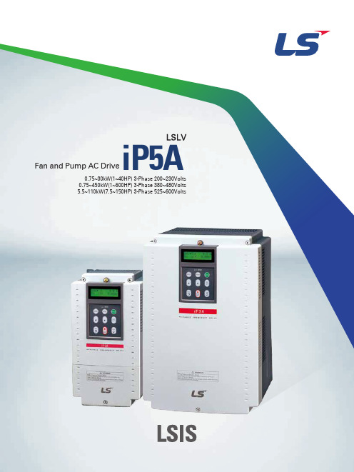
Fan and Pump AC Drive0.75~30kW(1~40HP) 3-Phase 200~230Volts 0.75~450kW(1~600HP) 3-Phase 380~480Volts 5.5~110kW(7.5~150HP) 3-Phase 525~600VoltsiP5ALS Starvert SV-iP5A has been specifically designedand created to provide competitive solutions for fanand pump applications2Overview Model & TypeStandard Specifications WiringTerminal Configurations (Power Circuit Terminal)Terminal Configurations (Control Circuit Terminal)Programming KeypadProgramming Keypad (Parameter Navigation)Parameter Description Trial Run DimensionsDB (Dynamic Braking) UnitExternal DB Resistor / Peripheral Device48913171922232437394550C o n t e n t sSTARVERTiP5AMarine Type Certification From DNV Specialized Functions for Fan and Pump Energy Saving and High EfficiencyUser-friendly Interface and Easy MaintenanceIntelligent Control Mechanism3Drive Starvert iP5A SeriesSpecialized Functions for Fan and PumpThe iP5A, specifically designed for HVAC application, provides stable and cost-effective system performance.In the centrifugal fan and pump field, PID control is provided as a standard function in order to maintain a constant control of pressure, flow and oil level. This function includes Pre-PID, Sleep and Wake up and output inverse sub-functions.PID ControlWhere external or cascaded PID control is required, the built-in dual PIDalgorithm of the iP5A can be utilized to satisfy various system requirements.Dual PIDMulti Motor Control (0.75~450kW)The iP5A MMC function provides cost-effective, simultaneous control of up to eight motors, without requiring external controllers.Marine Type Certification From DNVThe iP5A has been tested and certified by DNV to comply with International Marine requirements40.750.500.400.250.200.1010203040506070Load %Conventional drive controliP5ADamper controlReduction percentage600RPMV/F30% manual energy saving Automatic energy savingEnergy Saving and High EfficiencyThe iP5A, specifically designed for fan and pump applications, guarantees energy savings by optimizing the system.Load change may incur energy losses but the optimized flux control of iP5A results in more outstanding energy saving compared to previous models.Automatic Energy SavingEnergy savings are obtained through the Sleep and Wake-Up functions of the iP5A, which enable the drive to automatically switch off during user-programmed low-load conditions and then to start up again when process demand increases.Sleep and Wake-up FunctionWhen using the drive in damp conditions, this function protects both the motor and the drive's outputPre Heating FunctionWhen 2 or more fans, or a high inertia load are connected to the drive, the iP5A detects the motor speed after a momentary power failure, enabling the motors to be smoothly reaccelerated without mechanical and electrical shock-loading to the system.Flying Start FunctionPID referencePID feedbackRun commandOutput frequencyWake-up mode Returning to normal stateSleep mode Adjusting output with detecting load(Energy saving)Industrial Drive for Fan and Pump STARVERT iP5A5Drive Starvert iP5A SeriesDuring unexpected power failure conditions, the iP5A can bring the load to a controlled stop, by utilizing the inertial energy. This can prevent further process problems or accidents.Safety StopThis algorithm reduces deceleration time, thereby improving system efficiency.Flux Braking AlgorithmIntelligent ControlBy taking ambient temperature into account, the iP5A can automatically adjust the Carrier (Modulation) Frequency.Automatic Carrier Frequency ChangeThe iP5A has optimized protective functions, such as safety stop and pre-excitation of the motor, amongst others.ProtectionBecause of effectual functions and protection algorithms, the iP5A provides constant performance,in spite of external power fluctuations.During Power Dips or Momentary Power Outage, the drive output can be maintained by utilizing the residual mechanical energy in the load as a regenerative source. The duration of the power-dip ride-through depends on the load characteristics.Improved System Management during Power Dips and Momentary Power OutagesIn spite of external voltage fluctuations and lightning surges, the iP5A optimizes motor performance.Constant and Stable PerformanceUnder damp conditions, leakage currents can occur when using drives. These currents can cause a system failure. The iP5A low-leakage PWM algorithm reduces these leakage currents to ensure reliability of operation.Current Leakage Reduction AlgorithmZero vector Zero vectorValid vector PWM Valid vectorPower failure for 1 secondPower failure for 3 secondsMecha -nical energyLoadMechanical energyConsumed energyE m i t t e d e n e r g yThe mechanical energy stored during blackout can be used for driveユs power.6Easy StartWhen pushing ‘STOP ’ key for 2~3 seconds in case drive turns on, the drive turns into ‘Easy Start Mode ’ with FWD, REV, and STOP command. ‘SHIFT/ESC ’ can return it to previous mode.Control method: V/F Control frequency: JogUser-friendly Keypad & Easy MaintenanceNPN/PNP InputiP5A has both NPN and PNP input, and you can select one of them easily.Abundant I/O SuggestioniP5A serves abundant I/O.Various Units of I/O DisplayThe iP5A display can be calibrated in many different types of process units.Built-in RS485 and Optional CommunicationThe built-In RS485 allows for communication without external option.However, the optional communication boards enable the iP5A to talk to BMS and most Industrial SystemsLong-life Condenser and Simple FrameworkiP5A adopts long-life condenser and enables easy maintenance in simple framework.Consumption Time DisplayiP5A displays consumption time of components so that users can replace them in time.Others•Removable terminal board •External fan available •Cooling fan on/off control3145672384126The iP5A construction allows for easy maintenance, with ease-of-access to all components.579Digital Input/OutputAnalog Input (Voltage + Current)/Output Pulse Input NTC/PTC Input8 points / 4 points (1+1) points /4 points 1 point 1 pointIndustrial Drive for Fan and Pump STARVERT iP5A7Drive Starvert iP5A SeriesSV 055iP5A2NE200~230V Class380~480V ClassMotor Rating0.75kW (1HP)1.5kW (2HP)2.2kW (3HP)3.7kW (5HP)5.5kW (7.5HP) 7.5kW (10HP)11kW (15HP) 15kW (20HP) 18.5kW (25HP) 22kW (30HP) 30kW (40HP) 37kW (50HP) 45kW (60HP) 55kW (75HP) 75kW (100HP) 90kW (125HP) 110kW (150HP) 132kW (200HP) 160kW (250HP)220kW (300HP) 280kW (350HP) 315kW (400HP)375kW (500HP) 450kW (600HP)SV008iP5A-4NE SV015iP5A-4NE SV022iP5A-4NE SV037iP5A-4NE SV055iP5A-4NE SV075iP5A-4NE SV110iP5A-4NE SV150iP5A-4NO SV185iP5A-4NO SV220iP5A-4NO SV300iP5A-4NO SV370iP5A-4O SV450iP5A-4O SV550iP5A-4O SV750iP5A-4O SV900iP5A-4O SV1100iP5A-4OL SV1320iP5A-4OL SV1600iP5A-4OL SV2200iP5A-4OL SV2800iP5A-4OL SV3150iP5A-4O SV3750iP5A-4O SV4500iP5A-4O380~480V Class (Classification)SV055iP5A-4NE (CLASS)SV075iP5A-4NE (CLASS)SV110iP5A-4NE (CLASS)SV150iP5A-4NOL (CLASS)SV185iP5A-4NOL (CLASS)SV220iP5A-4NOL (CLASS)SV300iP5A-4NOL (CLASS)SV370iP5A-4OL (CLASS)SV450iP5A-4OL (CLASS)SV550iP5A-4OL (CLASS)SV750iP5A-4OL (CLASS)SV900iP5A-4OL (CLASS)SV1100iP5A-4OL (CLASS)SV1320iP5A-4OL (CLASS)SV1800iP5A-4OL (CLASS)SV2200iP5A-4OL (CLASS)SV2800iP5A-4OL (CLASS)SV3150iP5A-4O (CLASS)SV3750iP5A-4O (CLASS)SV4500iP5A-4O (CLASS)525~600V ClassSV055iP5A-6SV075iP5A-6SV110iP5A-6SV150iP5A-6SV185iP5A-6SV220iP5A-6SV300iP5A-6SV370iP5A 6SV450iP5A-6SV550iP5A-6SV750iP5A-6SV900iP5A-6SV1100iP5A-6SV008iP5A-2NE SV015iP5A-2NE SV022iP5A-2NE SV037iP5A-2NE SV055iP5A-2NE SV075iP5A-2NE SV110iP5A-2NE SV150iP5A-2NO SV185iP5A-2NO SV220iP5A-2NO SV300iP5A-2NOModel & Type(CLASS)N: No Keypad Input Voltage Motor Rating Series NameClassification8Industrial Drive for Fan and Pump STARVERT iP5AStandard SpecificationsNote 1) Rated capacity (v 3。。V 。。I) is based on 220V for 200V class and 460V for 400V class. 2) Indicates the maximum applicable capacity when using a 4-Pole LS motor. 3) Maximum output voltage will not exceed the input voltage. An output voltage less than the input voltage may be programmed if necessary. 4) IP20/UL Type1 with optional conduit, it can be modified to UL Type1.380~480V Class (0.75~90kW / 1~125HP)200~230V Class (0.75~30kW / 1~40HP)9Drive Starvert iP5A SeriesStandard Specifications525~600V Class (5.5~110kW /7.5~150HP)Note 1) Rated capacity (v 3 X V X I) is based on 220V for 200V class and 460V for 400V class. 2) Indicates the maximum applicable capacity when using a 4-Pole LS motor.3) Maximum output voltage will not exceed the input voltage. An output voltage less than the input voltage may be programmed if necessary.4) IP20/UL Type1 with optional conduit, it can be modified to UL Type1.10Industrial Drive for Fan and Pump STARVERT iP5A(1) Rated capacity (√3×V×I ) is based on 220V for 200V class and 460V for 400V class. (2) Indicates the maximum applicable capacity when using a 4-Pole standard motor.(3) IP20 or UL Enclosed Type1 can be provided by the option. (4) IP20 or UL Enclosed Type1 is not provided.(5) Overload rating 120%, 1 min is based on ambient 25℃Common SpecificationsStandard Specifications Common Specifications (External)Industrial Drive for Fan and Pump STARVERT iP5A WiringFor 0.75~30kW (1~40HP)Note 1) 5G is Common Ground for Analog Input / Output. (Only applied to 0.75 ~ 30kW products)WiringFor 37~90kW (50~125HP) / 315~450kW (400~600HP)Note 1) 5G is Common Ground for Analog Meter Output (SO, S1) and External motor thermal detection (ET). CM is Common Ground for Analog input.Industrial Drive for Fan and Pump STARVERT iP5A For 110~280kW (150~350HP)Note 1) 5G is Common Ground for Analog Meter Output (SO, S1) and External motor thermal detection (ET). CM is Common Ground for Analog input.WiringFor 15~30kW (20~40HP) Built-in DCL TypeFor 37~90kW (50~125HP) Built-in DCL TypeIndustrial Drive for Fan and Pump STARVERT iP5A Terminal Configurations (Power Circuit Terminal)0.75~30kW (1~40HP) <200V/400V/600V Class>37~90kW (50~125HP) / 315~450kW (400~600HP) <400V/600V Class>15~18.5kW (20~25HP) <Built-in DC Reactor Type, 400V Class>22~30kW (30~40HP) <Built-in DC Reactor Type, 400V Class>37~90kW (50~125HP) / 110 ~280kW (150~350HP) <Built-in DC Reactor Type, 400V Class>Note) P1 (+) is not provided for wiring.Terminal Configurations (Power Circuit Terminal) GroundingWires & Terminal lugsIndustrial Drive for Fan and Pump STARVERT iP5ATerminal Configurations (Control Circuit Terminal)0.75~30kW / 1~40HP (200V/400V Class)37~450 kW/50~600HP (400V Class)Terminal Configurations (Control Circuit Terminal)Note) NC terminal is unavailableIndustrial Drive for Fan and Pump STARVERT iP5ASink mode (NPN mode)•Put J1 switch down to set to Sink mode (NPN mode). CM terminal (24V GND) is common terminal for contact signal input.•The factory default is Sink mode (NPN mode).Source mode (PNP mode) Internal Power Supply Used•Put J1 switch up to set to Source mode (PNP mode). Terminal 24 (24V Power Supply) is common terminal for contact input signal.Source mode (PNP mode) External Power Supply Used•Put J1 switch up to set to Source mode (PNP mode).•To use external 24V Power Supply, make a sequence between external Power Supply (-) terminal and CM (24V GND) terminal.iP5A provides Sink/Source (NPN/PNP) modes for sequence input terminal on the control circuit. The logic of the input terminal is settable to Sink mode (NPN mode)/Source mode (NPN mode) by using the J1 switch. Connection method is shown below.Programming Keypad LCD LoaderIndustrial Drive for Fan and Pump STARVERT iP5A Programming Keypad (Parameter Navigation)Parameter group moves directly to DRV group by pressing [SHIFT] key in any parameter code.Parameter Descriptioneither [Speed] (Hz or Rpm), [Percent], [Bar], [mBar], [kPa] or [Pa]. Output Frequency (Hz or Rpm; Unit of outupt speed) is displayed in DRV-00 during the Drive is running. User Unit reference (Unit of PID controller selected) is displayed in DRV-00 during the Drive is not running.2) DRV-15, DRV-18 will appear when APP-02 [Process PI Mode] is set to メYesメ. Also User Unit is displayed when one of I/O-86~ I/O-88 is set to either [Speed](Hz or Rpm), [Percent], [Bar], [mBar], [kPa] or [Pa]. 3)DRV-20 will appear when APP-80 [ExtProcess PI Mode] is set to メYesメ. 4) DRV-91/92 will appear only when DRV-22 is set to [2nd Source].Industrial Drive for Fan and Pump STARVERT iP5AParameter DescriptionFU1-41~48 only displayed when FU1-40 is set to ‘User V/F’.10) Only displayed when FU1-51 is set to ‘Manual’.11) Only displayed when FU1-66 is set to ‘Yes’.31) Only displayed when FU1-75 is set to ‘Yes’.Industrial Drive for Fan and PumpSTARVERT iP5A14) FU2-26 is displayed when FU2-25 [Retry number] is set to [1~10]. 15) FU2-64 is displayed when FU2-60 is set to [Sensorless].Parameter DescriptionFU2-64 is displayed when FU2-60 is set to [Sensorless].Table 1) Switching frequency and fatory default value for each drive capacityIndustrial Drive for Fan and Pump STARVERT iP5AW hen DRV-04 is set to either V1, V1S, I or V1+I or Pulse, only selected item codes are displayed in I/O-1~I/O-19.18) I /O-3,5,8,10,14,16 is displayed 0~100.00 [**] when App-02 is set to [proc PI mode] or APP-80 is set to [Ext PImode] and APP-06 PID Feedback Signal Selection is set to one of I, VI, Pulse, after then, one of I/O-86 ~I/O-88 is set to percentage, Bar, mBar, kPa, Pa except for Speed. Unit will be changed to selected unit. Only user unit displayed when APP-02 or APP-80 is set to [Yes], after APP-06 is set to one of I, V, Pulse, after then one of I/O-86 ~I/O-88 is set to either speed, percentage, Bar, mBar, kPa, Pa..Parameter DescriptionIndustrial Drive for Fan and Pump STARVERT iP5A21) I/O-74 ~ I/O-75 displayed only when one of I/O-76 ~ I/O-79 is set to either FDT-1~FDT5Parameter Description38400 bps can be set only when the external communication option card is installed.23) Only I/O-92 ~ I/O-93 displayed when DRV-03/04 is set to [int485].Industrial Drive for Fan and Pump STARVERT iP5AOnly APP-03 ~ APP-17 displayed when APP-02 is set to [Yes]. Only APP-03 ~ APP-17 and APP-63 ~ APP-65 displayed when APP-2 is set to [Yes].26) If APP-04 Aux Ref Mode is no set, DRV-04 setting will be reference of process PID. And APP -05 setting will be ignored27) If APP-04 is set, APP-04 will appear. And APP -05 setting value will be reference of process PID, DRV-04 setting will be ignored.28) Only APP-20 ~ APP-29 displayed only when one of I/O-20 ~ I/O-27 is set to either 。。2nd Func 。。.O nly APP-40 ~ APP-71 displayed when APP-01 is set to [MMC].30) O nly APP-81 ~ APP-97 displayed when APP-80 Ext PI mode is set to [Yes].Parameter DescriptionIndustrial Drive for Fan and Pump STARVERT iP5A* Only the above EXT group displayed when the corresponding option board is installed.* Refer to the SUB board option manual for details.COM GROUPParameter Description* Only the above COM group displayed when the corresponding option board is installed.* COM-61~66 parameter is used to LonWorks and BACnet communication.Industrial Drive for Fan and Pump STARVERT iP5A Trial RunOperation Example (1)V/F Control + Analog Voltage Input (V1)+ Operation via Terminal (FX/RX)Operation condition•Control mode: V/F control•Frequency command:50 [Hz] analog input via V1 terminal•Accel/Decel time: Accel -15 [sec],Decel -25 [sec]•Drive mode: Run/Stop via FX/RX terminal,Control terminal: NPN modeTrial RunV/F control + Analog input (V1S)+ Operation via terminal FX/RXOperation condition•Control mode: V/F control •Frequency command:Setting 50 [Hz] via Analog input (V1S)•Accel/Decel time: Accel time 15 [sec], Decel time 25 [sec]•Drive mode: Run/Stop via FX/RX,Control terminal: NPN modeIndustrial Drive for Fan and Pump STARVERT iP5A DimensionsSV008~055iP5A (200/400V Class) & SV055~110iP5A (600V Class)SV075~300iP5A (200/400V Class) & SV150~300iP5A (600V Class)DimensionsIndustrial Drive for Fan and Pump STARVERT iP5ASV370~SV550iP5A (400V Class) & SV370~550iP5A (600V Class)41Drive Starvert iP5A SeriesDimensions42Industrial Drive for Fan and Pump STARVERT iP5A SV750, 900iP5A (UL Type 1 or UL Open Type with Conduit Option used, 400V Class)43Drive Starvert iP5A Series44Industrial Drive for Fan and Pump STARVERT iP5ADB (Dynamic Braking) UnitTerminal Configuration•Group 1 -•Group 2 -•Group 3 -CM G POH N NB2GG P/B1B1B2B2B1N P45Drive Starvert iP5A SeriesWiring for DB unit and DB resistor (For 5.5~90kW/7.5~125HP drives)46Industrial Drive for Fan and Pump STARVERT iP5A DB (Dynamic Braking) UnitGroup 147Drive Starvert iP5A SeriesGroup 248Industrial Drive for Fan and Pump STARVERT iP5A DB (Dynamic Braking) UnitGroup 349Drive Starvert iP5A SeriesExternal DB ResistoriP5A do not have built-in DB resistor on power stack as factory installation. External DB Unit and Resistor (Optional) should be installed. See the following table for more details (ED: 5%, Continuous Braking Time: 15 sec). If Enable duty (%ED) is increased to 10%, use external DB resistor having twice Wattage rating.50。
松下变频器VF-7F说明书
松下变频器VF-7F说明书VF-7F松下变频器的操作说明书参数设定参数序号参数名称设置对象设定值或代码出厂设置01 第一加速时间设置加速时间:从0.2Hz到最高输出频率0000:40毫秒,0.1-1600秒**005.002 第一减速时间设置减速时间:从最高输出频率到0.2Hz 0000:40毫秒,0.1-1600秒**005.003 频率范围设置伏/赫方式 50 60 FF(50:50Hz,FF自由方式)6004 伏/赫曲线设置伏/赫曲线 0 1 0:恒定转矩,1:降减转矩 005 直流转矩提升设置转矩提升值 0-40% 0.506 过载保护功能选择热过载保护功能0:无过载保护功能,1:加保护且不降低输出频率2:加保护但降低输出频率,3:用于特种电动机 207 过载电流设定电流值 0.1-300A *08 自控/外控设定自控或外控方式 0-6 009 自控/外控频率自控或外控设定控制频率(伏/安)0:自控1:VR(10k) 2:0-5V 3:0-10V 4:4-20mA 010 反转锁定设置成只能正转 0:正转/反转 1:正转(不反转) 011 停止方式选择高定减速停止或惯性停止0:减速停止1:惯性停止 012 停止频率设定停止频率 0.2-60Hz 00.5013 直流制动时间设定直流动态制动时间 000:无直流制动功能。
0.1-30秒 00014 直流制动电子设定直流动态制动电平 0-100 0015 最大频率设定最大输出频率 50-400Hz 60.0016 基础频率设定基础频率 45-400Hz 60.0017 加速频率保持设定防止加速失速功能0:无失速保护功能1:有失速保护功能 118 减速频率保持设定防止减速失速功能0:无失速保护功能1:有失速保护功能 119 多速功能设定选择多速功能 0:多速 1:加/减速 2:加/减速与多速连动 020 多功能输入选择选择SW1、2和SW3的功能设定值有:0、1、2、3、4、5、6、7、8、9、10 021 仅供制造商使用 ------ ------- --22 辅助联锁装置选择辅助联锁装置跳闸功辅助停止0:辅助联锁跳闸装置 1:辅助停止 023 输出端子选择选择检测频率功能,选择输出端子功能0:运行信号;1到达信号;2:过载信号; 3:频率检测信号;4:反转信号 024 输出继电器选择选择输出继电器功能0:运行信号;1到达信号;2:过载信号;3:频率检测信号;4:反转信号;5:故障信号(加电时)6:故障信号(不加电时) 525 检测频率(输出端子) 设定检测频率值 0000,0.2-400Hz 00.5026 检测频率(输出继电器) 设定检测频率值0000,0.2-400Hz 00.5027 点动频率设定点频率值 0.2-20Hz 10.0028 点动加速时间设置点动加速时间 0000:40毫秒,0.1-1600秒**005.029 点动减速时间设置点动减速时间 0000:40毫秒,0.1-1600秒**005.030 预设第2频率设定第2频率 0000:0V停止,0.2-400Hz 20.0031 预设第3频率设定第3频率 0000:0V停止,0.2-400Hz 30.0032 预设第4频率设定第4频率 0000:0V停止,0.2-400Hz 40.0033 预设第5频率设定第5频率 0000:0V停止,0.2-400Hz 15.0034 预设第6频率设定第6频率 0000:0V停止,0.2-400Hz 25.00。
飞利浦无尘袋吸尘器5000系列产品细节说明书

Philips 5000 Series无尘袋吸尘器1700 瓦第七代飓风离尘技术Allergy H13 滤网强力毛刷吸嘴FC9573第七代飓风离尘技术赋予强大性能处理灰尘方便卫生飞利浦无尘袋吸尘器 5000 系列是我们功能强大的真空吸尘器。
凭借第七代飓风离尘技术和 TriActive 喷嘴,一次完成三种清洗操作,可轻松实现出色的清洁效果。
出众的性能•Allergy H13 过滤系统可吸附 >99.9% 的细尘•第 7 代飓风离尘技术可以提供更长时间的强劲吸力•强劲的 1700 瓦马达可产生强大吸力•TriActive 吸嘴,可进行 3 向彻底清洁操作•强力毛刷吸嘴,适合清洁(宠物)毛发和绒毛•吸力控制功能可调节吸力大小省力清洁•简约设计,前部和顶部把手便于携带•把手和家具吸嘴附带软毛刷•软缓冲装置和橡胶滚轮,可保护家具•集尘桶采用卫生设计,单手即可清空灰尘产品亮点小巧轻便紧凑、轻便的设计确保存储方便并可轻松提起吸尘器。
设计包括顶部和前部把手,携带轻松便捷。
毛刷和家具吸嘴把手内置有除尘毛刷,因此可随时在家具、平面和家具织物上使用。
家具吸嘴专为清洁靠垫、沙发和扶手椅等柔软家具设计,甚至可去除宠物毛发。
软缓冲装置和橡胶滚轮软缓冲装置和橡胶滚轮,可保护家具和防止刮擦地板,轻松实现在家中简便操作。
卫生地处理灰尘方便清空的集尘桶,专为单手进行卫生处理而设计,这有助于减少扬尘。
Allergy H13滤网Allergy H13 过滤系统可吸附 >99.9% 的细尘颗粒(包括花粉、宠物毛发和尘螨),很适合过敏患者。
过滤等级相当于 HEPA 13*。
Power Cyclone 7第七代飓风离尘技术PowerCyclone 7 技术采用空气动力学设计,有效地减少空气阻力并确保提供持久强大的吸力。
使空气加速进入圆柱形气旋室,且采用出众的出口叶片,可以高效地使灰尘与空气分离。
强劲的1700 瓦马达1700 瓦马达可产生高达 415 瓦的强大吸力,提供强劲性能并实现深度清洁效果。
