B13_PC-BDC_XFACTORS SPEED教程
B05_PC-BDC_SLOTFILL SPEED教程

for slot (b), and 628% for slot (c). This method does not really work for rectangular conductors. Fig. 2 shows a rectangular slot with rectangular conductors. Try to guess the gross slotfill factor SFg for this slot. The answer is given on page 4. Finally Fig. 3 shows another effect which is not related to slot-fill, but makes good use of these coloured diagrams. If the conductors are crowded towards the bottom of the slot, the slot-leakage inductance is increased. If they are crowded towards the top of the slot, the slot-leakage inductance is decreased.
Zslot 12 × 2 × 4 × 3 24 12
2
The cross-section area of one conductor is B/4 × 20 2 314 mm .
SFg 24 × 314 0482 1565672
Fig. 8
Wire size
or 482%. This can be checked in the design sheet.
Digi ESP for Python 用户指南说明书
Quick Note 059Use Digi ESP for Python on a TransPort router to upload PPP Stats to Digi Remote Manager as DataPoints.19 September 20171 Introduction (3)1.1Outline (3)1.2Assumptions (4)1.3Corrections (4)1.4Version (4)2 Digi ESP For Python Installation (5)3 Digi ESP Configuration (6)3.1 Device Manager Configuration (6)3.2 Create a new Project (8)3.3 Download and Copy the PPP Stats device (10)4 Configure Digi ESP Project (13)4.1 Add the new PPP stats device in the project (13)5 Run DIA Project on the TransPort Router (15)6 Verify DATA STREAMS on Remote Manager (18)7 Notes (19)1.1OutlineThis document will describe how to push mobile statistics (ppp stats) as Data Points to Remote Manager using Digi ESP for Python. The example will use the PPP statistics but most other values can be used by modifying the driver. This will be described in the document.The PPP statistics consist of the cellular mobile data IN and OUT combined. This is useful to show the amount of cellular data used by a device.Please note: The document will assume that a Remote Manager account has previously been created and a Digi TransPort router has been added to this account.To create a developer test account on Remote Manager, please use the following URL:/For help on configuring a Digi TransPort router for Remote Manager, please visit the following page: /articles/Knowledge_Base_Article/Configuring-a-Digi-TransPort-router-for-Remote-Manager-connectivity-Web-User-Interface-WebUI-method1.2AssumptionsThis guide has been written for use by technically competent personnel with a good understanding of the communications technologies used in the product and of the requirements for their specific application.This quick note applies only to:Model: Digi TransPort WR11, WR21, WR31, WR441.3CorrectionsRequests for corrections or amendments to this documentation are welcome and should be addressed to: *********************Requests for new quick notes can be sent to the same address.1.4VersionDownload Digi ESP for Python from the Digi Support Web site:https:///support/productdetail?pid=3632&type=driversStart the installation and follow the instructions on the screen.When requested to select the “workspace” make sure to note the location as it will be required to navigate to that directory in the next steps.3.1Device Manager ConfigurationStart Digi ESP for PythonOn the top toolbar, click on Device Options and click Device ManagerClick on New Remote ConfigurationEnter a name for this configuration, in this example, a TransPort WR21 will be used so “WR21” is used for Name.Chose TransPort WR21 for the device type and Local Area Network for the Connection ModeUnder LAN Connection, enter the IP Address of the TransPort router.Under Authentication, enter the username and password for this device. By default, “username/password”Please note: It is possible to do the above steps via Remote Manager by selecting “Connect to device using Device Cloud by Etherios” under the General tab.Click on Set Current3.2Create a new ProjectClick on File > New > DIA ProjectGive the project a name, in this example: PPPstatsSelect the location where this project will be saved (typically the default workspace, please note this path as it will be needed in the next step)Make sure to check the box “Include DIA source code in project”Click NextIn the next screen, select “Use Current Remote Device”Click Finish3.3Download and Copy the PPP Stats devicePlease note: Make sure to c lose Digi ESP for Python before proceeding below.Download the following python file (or copy the content shown below) and paste it into the “devices” folder on the previously created project. In this example: C:\Temp\PPPstats\src\devices\/support/documentation/ppp_stats.zipContent of the python file below to create it manually:############################################################################ # # # Copyright (c)2008, 2009, Digi International (Digi). All Rights Reserved. # # # # Permission to use, copy, modify, and distribute this software and its # # documentation, without fee and without a signed licensing agreement, is # # hereby granted, provided that the software is used on Digi products only # # and that the software contain this copyright notice, and the following # # two paragraphs appear in all copies, modifications, and distributions as # # well. Contact Product Management, Digi International, Inc., 11001 Bren # # Road East, Minnetonka, MN, +1 952-912-3444, for commercial licensing # # opportunities for non-Digi products. # # # # DIGI SPECIFICALLY DISCLAIMS ANY WARRANTIES, INCLUDING, BUT NOT LIMITED # # TO, THE IMPLIED WARRANTIES OF MERCHANTABILITY AND FITNESS FOR A # # PARTICULAR PURPOSE. THE SOFTWARE AND ACCOMPANYING DOCUMENTATION, IF ANY, # # PROVIDED HEREUNDER IS PROVIDED "AS IS" AND WITHOUT WARRANTY OF ANY KIND. # # DIGI HAS NO OBLIGATION TO PROVIDE MAINTENANCE, SUPPORT, UPDATES, # # ENHANCEMENTS, OR MODIFICATIONS. # # # # IN NO EVENT SHALL DIGI BE LIABLE TO ANY PARTY FOR DIRECT, INDIRECT, # # SPECIAL, INCIDENTAL, OR CONSEQUENTIAL DAMAGES, INCLUDING LOST PROFITS, # # ARISING OUT OF THE USE OF THIS SOFTWARE AND ITS DOCUMENTATION, EVEN IF ## DIGI HAS BEEN ADVISED OF THE POSSIBILITY OF SUCH DAMAGES. # # # ############################################################################ # importsfrom devices.device_base import DeviceBasefrom settings.settings_base import SettingsBase, Settingfrom channels.channel_source_device_property import *from common.shutdown import SHUTDOWN_WAITimport threadingimport timeimport sarcli# constants# exception classes# interface functions# classesclass PPPStatsDevice(DeviceBase, threading.Thread):"""This class extends one of our base classes and is intended as anexample of a concrete, example implementation, but it is not itselfmeant to be included as part of our developer API. Please consult thebase class documentation for the API and the source code for this filefor an example implementation."""def __init__(self, name, core_services):self.__name = nameself.__core = core_services## Settings Table Definition:settings_list = [Setting(name='update_rate', type=float, required=False,default_value=1.0,verify_function=lambda x: x > 0.0),]## Channel Properties Definition:property_list = [# gettable propertiesChannelSourceDeviceProperty(name="pppdata", type=str,initial=Sample(timestamp=0, value=""),perms_mask=DPROP_PERM_GET, options=DPROP_OPT_AUTOTIMESTAMP,), ]## Initialize the DeviceBase interface:DeviceBase.__init__(self, self.__name, self.__core,settings_list, property_list)## Thread initialization:self.__stopevent = threading.Event()threading.Thread.__init__(self, name=name)threading.Thread.setDaemon(self, True)## Functions which must be implemented to conform to the DeviceBase## interface:def start(self):threading.Thread.start(self)return Truedef stop(self):self.__stopevent.set()self.join(SHUTDOWN_WAIT)if self.isAlive():raise RuntimeError("Could not stop %s" % self.__name)return True## Locally defined functions:# Property callback functions:# Threading related functions:def run(self):while 1:if self.__stopevent.isSet():self.__stopevent.clear()break# increment counter property:pppStats = getpppStats()self.property_set("pppdata", Sample(0,pppStats))time.sleep(SettingsBase.get_setting(self,"update_rate"))# internal functions & classesdef getpppStats():cli = sarcli.open()cli.write("at\mibs=ppp.1.dlim.totdata")ppp1totalstr = cli.read()beginningofppp1total = ppp1totalstr.find(".totdata = ")endofppp1total = ppp1totalstr.find("\n", (beginningofppp1total))ppp1total = ppp1totalstr[(beginningofppp1total+11):(endofppp1total-1)] cli.close()return ppp1totalRe-Open Digi ESP for Python4.1Add the new PPP stats device in the projectIn the Smart Project Editor, click on the Xbee Device Manager and Delete as this will not be needed.By default, the copied device will not be available.Now, click on Source to manually add the PPP stats device.In the “devices:” section, add the following:- name: pppstatsdriver: devices.ppp_stats:PPPStatsDevicesettings:update_rate: 60.0Make sure to keep the same indenting.Switch back to the “Graphic Editor”. A device named “PPPStatsDevice” should now be shown under “Devices”Please note: If Digi ESP shows an error message when switching back to the Graphic Editor, this is because the indenting has not been kept properly. Make sure to use only spaces and not tabs.Click on Run > Run As > Remote DIAThe left panel will show a progress barOnce the router has rebooted, the following will be displayed:In the URL bar on the center page, change the url to point to:/idigi_dia.htmlIn this example, http://192.168.1.22/idigi_dia.htmlThis will show the DIA Web presentation which is a simple web page showing the ppp stats value.The Right panel shows a Telnet Command Line interface allowing the user to see the CLI output of the same information shown on the web page. This is done by issuing a “channel_dump” command:Welcome to the Device Integration Application CLI.=>> channel_dumpDevice instance: edp_upload0Channel ValueUnit Timestamp------------------------ -------------------------- -------------------upload_samples (N/A)upload_snapshot (N/A)Device instance: pppstatsChannel ValueUnit Timestamp------------------------ -------------------------- -------------------pppdata 02017-06-21 09:20:40=>>Please note: For the value to increase and new data to be uploaded, the router must have a SIM card inserted and be configured to establish a cellular connection.The PPPstats Console is a debugging console showing the python’s script activity. Every 60sec (default value) it will show a message that data has been uploaded to Remote Manager:DEBUG:edp_upload0:Output List (1): {'pppstats.pppdata': (<type 'str'>, [<Sample: 0 at 2017-06-21T09:23:40Z>])}DEBUG:edp_upload0:<?xml version="1.0"?><idigi_data compact="True" version="1.1"><sample name="pppstats.pppdata" value="0" unit="" type="str"timestamp="2017-06-21T09:23:40Z" /></idigi_data>DEBUG:edp_upload0:Starting upload to Device CloudDEBUG:edp_upload0:Attempting to upload file_name19.xml to Device CloudDEBUG:edp_upload0:Successfully uploaded file_name19.xml to Device CloudLogin to: https:///login.do using the credentials from the created account. Navigate to Data Services > Data StreamsData Streams starting with “dia” show be shown:The “current value” field is the pppdata from the router sent by the python script.Clicking on one of the stream also allows showing this in a charts format:While this example shows the cellular data used, it is possible to modify it to use various other information.The key part of the script that actually pulls the data from the Command Line interface of the router is found at the bottom of ppp_stats.py:def getpppStats():cli = sarcli.open()cli.write("at\mibs=ppp.1.dlim.totdata")ppp1totalstr = cli.read()beginningofppp1total = ppp1totalstr.find(".totdata = ")endofppp1total = ppp1totalstr.find("\n", (beginningofppp1total))ppp1total = ppp1totalstr[(beginningofppp1total+11):(endofppp1total-1)]cli.close()return ppp1totalThis line is the CLI command sent to the router:cli.write("at\mibs=ppp.1.dlim.totdata")You can get the list of available commands on the router by issuing at\mibsThe number of character calculation as well as the characters to search for will need to be modified to suit the CLI command used.Once modified, run the project as a Remote DIA like in section 5 and the new values will be available on the DIA page as well as on Remote Manager.。
Autodesk Nastran 2023 参考手册说明书
FILESPEC ............................................................................................................................................................ 13
DISPFILE ............................................................................................................................................................. 11
File Management Directives – Output File Specifications: .............................................................................. 5
BULKDATAFILE .................................................................................................................................................... 7
Synopsys OptoDesigner 2020.09安装指南说明书
3. Troubleshooting scanning issues........................................................25
Accidental full scan proliferation by folder paths which include build or commit ID............................ 25 Solution......................................................................................................................................25
Contents
Contents
Preface....................................................................................................5
1. Scanning best practices......................................................................... 8
pcdmis坐标系建立迭代法

第2页/共45页
导入CAD模型,并进行相关图形处理与操作, 注意对模型坐标系及被测元素的观察。
第3页/共45页
确认程序开头为“手动”模式
第4页/共45页
选择“自动特征”,打开自动测量矢量点对话框
第5页/共45页
确定当前模式为“曲面模式”
第6页/共45页
用鼠标在CAD模型“点1”位置点击一下,注意此点的法线 矢量方向。
第21页/共45页
定义起始标号: PC-DMIS会在重新测量迭代法建坐标系特征时转到此标号。
起始标号
未定义起始标号: PC-DMIS将转到组成迭代法建坐标系的第一个特征,从此处
开始进行DCC测量。
第22页/共45页
注意: 切勿将矢量点目标半径的值设置得太小(如50微米)。许多CMM无法准 确定位测头,使其接触极小目标上的每个测定点。所以最好将公差设置在5毫米 左右。如果重新测量无休止地继续,则将增加该值。
点目标半径
利用点目标半径,您可以在每个点周围指定一个大小为目标半径的假想公差 区域(或目标)。这样您就能接触指定公差内的任何位置。如果测定点不在此区域 内,PC-DMIS将以DCC模式重新测量该点。
第23页/共45页
• 如果将测量值拟合到理论值后,有一个或多个输入特征在 其指定基准轴上的误差超过此公差值,PC-DMIS 将自动转到 误差标号(如果有)。请参见误差标号。 • 如果未提供误差标号,PC-DMIS 将显示一条错误消息,指 出每个基准方向上的误差。然后,您将可以选择接受基准并 继续执行零件程序的其余部分,或取消零件程序的执行。
第12页/共45页
第13页/共45页
PCDMIS将自动在编辑窗口中创建该点的程序, 同时在视图窗口中出现“圆1”的标识
PCDMIS高级编程培训教材
2007-4-10
16
典型组合
2007-4-10
17
多测针的使用
在一个程序中,有时单个测针是不能完成所有检测项目的, 需要用到两个或两个以上的测针,这时多个测针之间测 量结果的一致性就是最关键的问题。
2007-4-10
4
薄壁类零件的装夹
薄壁件存在变形的影响 ,因此其装夹对检测结果的影响很 大。 最好的装夹方式是按照理论位置组合夹具,然后把零件 放在夹具上,并在相应位置夹紧。 在选择支撑和夹紧位置时,应当选择和其他零件配合的 位置或者决定整个零件结构的关键位置。 对于夹具有以下要求:一是夹具应具有足够的精度和刚 度;二是夹具应有可靠的定位基准;三是要有夹紧装 置。 在薄壁件的检测中,通常有以下三种类型的夹具: 1.通过软件控制的柔性夹具,如FIVE; 2.按照理论值专门定做的专用夹具; 3.使用相关检具。
程。
2007-4-10
22
3-2-1建立零件坐标系
无CAD模型时3-2-1坐标系的建立
方法Ⅰ a.建立坐标系第一轴向 b.建立坐标系第二轴向 c.确定坐标系原点
a
b
c
方法Ⅱ 通过旋转平移当前坐标系建立新的坐标系
2007-4-10
围绕某一轴向(如z 正)旋转另一轴向 (如x正)(按右手定 则顺时针为负值,逆 时针为正值)
2007-4-10
10
星形测针的校验
星形测针
星型测杆的定义及校验(以 PS7R为例)
1. 新建一个测头文件 2. 在“测头说明”里选择测头组件:
PH10MQ CONCERT30MM_TO_M8THRD PROBE_TP20 EXTEN20MM
西门子技术问题总汇

文档标题
如何设置模拟量输入模板 SM 431-7KF00的温度补偿? 如何解决 SIMATIC BATCH 的 IL43基本设备上 hotfix 安装的问题? 如果通过 PCS7 V6.1 SP1 DVD 单独安装 SIMATIC BATCH Report 需要注意哪些设置? 为什么冗余模拟量输出模块的每个通道只有一半电流输出? 使用WinCC/Web Navigator V6.1 SP1需要什么样的操作系统和软件? 是否 COM PROFIBUS 可以使用所有版本的 GSD 文件? 如何在 WinCC flexible 中组态与S7 控制器的 Profinet 连接? 如何在操作面板上设定定时器时间, 同时如何输出定时器的剩余时间? 数据块初始值与实际值的含义 如何通过窗口对象滚动条步进调节过程值参数? 使用 SINAUT ST7 向电子邮箱接受方发送文本信息 SMS 需要做何设置? 可以使用CPU317-2PN/DP替代在iMap中组态的CPU315-2PN/DP吗? 什么情况下插入C-PLUG卡或者C-PLUG有什么作用? 通过一台PC,可以使用哪种方式访问与IWLAN/PB link PNIO或IE/PB link PNIO连接的PROFIBUS设备? 当在SINAUT网络中使用4线变压器应该注意哪些设置? 在 SINAUT 网络中,使用MD3拨号调制解调器作为专线调制解调器时,要进行哪些设置? 如何安装 DCF77 天线, 当选择 DCF77 天线时需要注意什么? 使用SINAUT ST7向传真机发送文本信息时,需要进行哪些设置? 在 SINAUT 项目中发送短消息必须进行哪些特殊服务的设置? 如何在S7-300 PN CPU和CP343-1之间建立一个open TCP 通讯连接,以及如何进行数据交换? 如何在两个S7-300 PN CPU之间建立一个open TCP 通讯连接,以及如何进行数据交换? 哪些控制系统可以成功与SINAUT ST7一起使用? 使用“零-Modem”电缆连接 TIM 模块应该注意什么? 当用 SINAUT 诊断工具的ST1协议进行诊断时,为什么TIM的状态不能显示? TIM 3V-IE 和 TIM 3V-IE Advanced 模块在以太网上通信时使用哪个端口号? 如何对没有接入网络的S7-200CPU编程? 掉电后,LOGO!的程序会丢失吗? 从 PCS7 V6.1 起,为什么没有分配任何 hierarchy (PH) 的 测量点(变量)通过编译不能在OS中自动创建相应的变量? 在SFC中,如何实现从一个 Sequencer 跳出后回到另一个 Sequencer 的某个固定位置并继续执行? 如何实现过程变量的平均值归档? 存储文件的目标路径和备份可选路径有何作用? WinCC变量归档中如何实现采集周期小于500ms的变量归档? 为什么在 OS 上会显示如下信息“时间跳变通知-永久切换为从站模式”? 在西门子A&D产品支持网站是否可以下载关于ET200M的手册? 在S7-400上怎样安装冗余电源? UDT改变后怎样更新使用UDT产生的数据块。 为什么在FB块中使用OUT变量赋值被调用FB块的IN变量时出现错误信息34:4469? 如何查看4-mation导入-导出错误 不能正确引导8212-1QU IBM/Lenovo M52 ThinkCentre 实时趋势更新缓慢的原因 如何保存变量名字典CSV文件的格式
DirectX函数大全

==============
DirectX
=================================================================
==============
获取显卡显示模式:
HRESULT GetAdapterDisplayMode(
UINT Adapter,
//指定显示卡序列号
D3DDISPLAYMODE *pMode
//存储显示模式的指针
);
=================================================================
==============
DirectX
=================================================================
3.纹理 ......................................... 4
从磁盘文件获取纹理.................................................2 设置当前要渲染的纹理............................................... 2
9.游戏音乐音效.................................... 4
5
D3D 基本框架
创建 D3D 对象: Direct3DCreate9(D3D_SDK_VERSION)
=================================================================
索引图形绘制........................................2
PC-DIMS使用循环的方法

•
•
1E-JUN04-Rev.C
界面的介绍
循环源程序
1E-JUN04-Rev.C
应用及报告
1E-JUN04-Rev.C
循环的使用
1E-JUN04-Rev.C
循环选项主要有三项用途: 循环选项主要有三项用途:
循环菜单选项用于有偏置或无偏置地重复执行零件程序( 循环菜单选项用于有偏置或无偏置地重复执行零件程序(或零件 程序的部分)。虽然“循环”命令在程序的开头和末尾最为有用, )。虽然 程序的部分)。虽然“循环”命令在程序的开头和末尾最为有用,但 可以将此函数添加到零件程序中的任何位置。主要用途如下: 可以将此函数添加到零件程序中的任何位置。主要用途如下:
• 1. 您具有一个多零件的夹具,用以夹持一个零件网格。 您具有一个多零件的夹具,用以夹持一个零件网格。夹具应在各行之 间使用一致的间距。利用平移/旋转偏置, 间使用一致的间距。利用平移/旋转偏置,您可以从零件网格中的一个零件转 换到下一个零件。 换到下一个零件。 2. 您具有夹持一个零件的夹具, 您具有夹持一个零件的夹具,并且想在每个程序循环之前换入新的零 将零件替换为新零件时,可借助于“注释” CMM。 件。将零件替换为新零件时,可借助于“注释”命令来停止 CMM。此命令 可以位于循环的开头或末尾。 可以位于循环的开头或末尾。 3. 您想使用“循环”选项来旋转零件程序,以测量同一零件的不同部分。 您想使用“循环”选项来旋转零件程序,以测量同一零件的不同部分。 例如,您可能会创建一个零件程序来测量一个复杂的孔模式, 例如,您可能会创建一个零件程序来测量一个复杂的孔模式,该模式在零件 您的零件程序只需要测量其中一个孔模式。然后, 上重复了 10 次。您的零件程序只需要测量其中一个孔模式。然后,可以使 循环”选项来偏置此零件程序, 个孔模式。 用“循环”选项来偏置此零件程序,以测量其它 9 个孔模式。
pcdmis高级培训(三坐标培训资料)
•
第6章:扫描功能的应用技巧
1.扫描类型· · · · · · · · · · · · · · · · · · · · · · · · · · · · · · · · · · · · · · 105 2.逆向工程中扫描的测头补偿· · · · · · · · · · · · · · · · · · · · · · 106 3.逆向工程中扫描的终止特征类型· · · · · · · · · · · · · · · · · · 107 4.逆向工程中扫描终止的通过次数· · · · · · · · · · · · · · · · · · 108 5.逆向工程中扫描曲面的分区及边界· · · · · · · · · · · · · · · · 109 6.扫描的速度、密度掌控实验数据· · · · · · · · · · · · · · · · · · 112 7.SP600M在PC-DMIS中的标准参数设置· · · · · · · · · · · · · · · 113
PC-DMIS 高级编程应用
-2-
目录
17.子程序· · · · · · · · · · · · · · · · · · · · · · · · · · · · · · · · · · · · · · · · · 52
•
第4章:应用实例
1.齿槽· · · · · · · · · · · · · · · · · · · · · · · · · · · · · · · · · · · · · · · · · · · 54 2.无规则排列特征的测量· · · · · · ·· · · · · · · · · · · · ·· · · · · · 62 3.轴承内圈 · · · · · · · · · · · · · · · · · · · · · · · · · · · · · · · · · · · · · · 68 4.曲线方程 · · · · · · · · · · · · · · · · · · · · · · · · · · · · · · · · · · · · · · 75 5.子程序的应用 · · · · · · · · · · · · · · · · · · · · · · · · · · · · · · · · · · 85
Win10怎么启用directx3D加速2种方法快速开启3D加速的图文步骤
Win10怎么启⽤directx3D加速2种⽅法快速开启3D加速的图⽂步骤怎么快速开启win10硬件directx 3D加速?win10系统3D硬件加速就是利⽤硬件所固有的快速特性,使画⾯更加的逼真、细腻和流畅。
在电脑中游戏时,通常我们都会开启3d硬件加速,因为这样我们才能玩⼀些⼤型的⽹络游戏。
电脑中如何开启3d硬件加速?这是近来不少朋友都向⼩编咨询的问题。
其实,硬件加速就是利⽤硬件模块来替代软件算法以充分利⽤硬件所固有的快速特性。
下⾯,就给⼤家带来的关于3d硬件加速怎么开启的内容,欢迎阅读!Win10系统开启3D加速的⽅法:⽅法⼀、⾸先同时按【WIN+R】键,打开【运⾏】对话框。
输⼊【dxdiag】,点【确定】打开【directx诊断⼯具】。
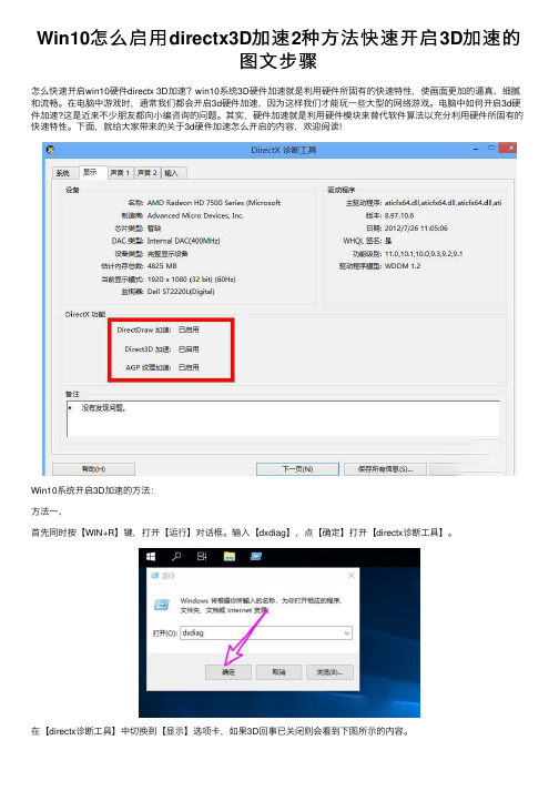
在【directx诊断⼯具】中切换到【显⽰】选项卡,如果3D回事已关闭则会看到下图所⽰的内容。
要重新开启3D加速,⾸先在桌⾯空⽩处右键选择【新建】-【⽂本⽂档】。
之后单击选中新建的⽂档,右键选择【重命名】,将其重命名为【开启3d加速.reg】。
⼀定要修改⽂件的后缀名。
要显⽰⽂件的扩展名,可以参考之前的经验,我将链接也加在了下⽅。
0⽂本⽂档怎么显⽰txt之后⽤记事本打开上⾯的.reg⽂件,输⼊如下内容:Windows Registry Editor Version 5.00[HKEY_LOCAL_MACHINE\SOFTWARE\Microsoft\DirectDraw] "EmulationOnly"=dword:00000000[HKEY_LOCAL_MACHINE\SOFTWARE\Microsoft\Direct3D\Drivers] "SoftwareOnly"=dword:00000000[HKEY_LOCAL_MACHINE\SOFTWARE\Wow6432Node\Microsoft\DirectDraw] "EmulationOnly"=dword:00000000[HKEY_LOCAL_MACHINE\SOFTWARE\Wow6432Node\Microsoft\Direct3D\Drivers] "SoftwareOnly"=dword:00000000保存并退出。
PC-Dm教材isforARM培训手册

PC-Dmis for ARM 培训手册说明感谢贵公司对Hexagon集团的信任与支持,选择海克斯康测量技术(青岛)有限公司的产品。
为了更好的使用关节臂便携式三坐标测量机,在进行任何操作前,请仔细阅读本操作规程中对应贵公司选购的产品部分。
目录说明 (2)第一章测量前的准备 (6)1.1.关节臂式测量机的分类 (6)1.2.轴的说明 (7)1.3.机器使用环境说明 (8)1.4.RA7机器的安装 (8)1.4.1.设备安装 (8)1.4.2.RDS软件安装 (16)1.4.3.RDS检查机器精度 (17)1.4.4.校准测头 (21)1.4.5.有线与无线切换 (23)1.4.6.按键使用及鼠标模式切换 (26)1.4.7.RDS简介 (27)1.5.STINGER机器 (32)1.5.1.设备安装 (32)1.5.2.软件安装 (36)1.5.3.WinRDS参数导入 (37)1.5.4.WinRDS介绍 (38)1.5.5.检查机器精度 (41)1.5.6.校准测头 (45)1.6.激光扫描测头连接 (47)1.6.1.CMS测头连线及校准 (47)1.6.2.RS测头连线及校准设置 (56)1.6.3.Perceptron测头连线及校准设置 (62)第二章三坐标测量的基础知识 (80)2.1.笛卡尔坐标系和矢量 (80)2.2.形位公差介绍 (81)第三章PCDMIS 安装与卸载 (86)第四章PCDMIS界面介绍 (87)第五章测量流程 (89)第六章测量基本操作 (90)6.1.手动测量及注意事项 (90)6.1.1.常规元素测量(手动特征测量) (90)6.1.2.测量注意事项 (95)6.2.自动测量特征 (95)6.3.构造特征 (100)6.3.1.构造点 (100)6.3.2.构造圆特征 (104)6.3.3.构造球特征 (107)6.3.4.构造直线特征 (108)6.3.5.构造平面 (111)6.3.6.构造锥体特征 (115)6.3.7.构造柱体特征 (116)6.3.8.构造集合元素 (117)第七章建立坐标系 (118)第八章测量实例 (120)8.1.利用图纸测量形位公差 (120)8.1.1.分析 (122)8.1.2.建立坐标系 (122)8.1.3.测量特征 (123)8.1.4.评价特征 (124)8.1.5.报告输出 (127)8.2.利用CAD数模测量形位公差 (129)8.2.1.分析 (130)8.2.2.建立坐标系 (130)8.2.3.测量特征 (133)8.2.4.评价 (136)8.2.5.输出报告 (138)8.3.利用CAD数模测量工装、检具类零件 (140)8.3.1.分析 (141)8.3.2.建立坐标系 (142)8.3.3.测量特征 (144)8.3.4.评价 (146)8.3.5.输出报告 (147)8.4.利用CAD数模测量钣金或冲压类零件 (149)8.4.1.分析 (149)8.4.2.建立坐标系 (151)8.4.3.测量特征 (154)8.4.4.评价 (155)8.4.5.输出报告 (156)8.5.利用CAD模型测量叶片类零件 (158)8.5.1.分析 (158)8.5.2.建立坐标系 (159)8.5.3.测量特征 (163)8.5.4.评价 (164)8.5.5.输出报告 (167)8.6.测量大型零件 (170)8.6.1.分析 (170)8.6.2.建立坐标系 (171)8.6.3.在程序中使用蛙跳 (172)8.6.4.测量特征 (174)8.6.5.评价 (175)8.6.6.输出报告 (176)第九章维护保养发货指导 (177)9.1.关节臂式测量机的维护和保养 (177)9.1.1.注意设备日常维护 (177)9.1.2.注意设备存放 (178)9.1.3.注意设备使用环境 (178)9.1.4.设备使用注意事项 (179)9.2.关节臂式测量机的运输 (180)9.2.1.安装和短距离运输 (180)9.2.2.长距离运输 (181)第十章常见问题 (183)第一章测量前的准备1.1.关节臂式测量机的分类海克斯康测量技术(青岛)有限公司目前主要提供两大类关节臂式测量机,一类为绝对臂测量机RA7系列,一类为Stinger系列。
PC-DMIS PRO 2010中文培训手册(M310-18-1C)
M310-18-1CPC-DMIS 2010 PRO FOR CMM 培训手册PCDMIS Manual Version 2010·PRO - CMM 1目录目录............................................................................................................................................1 第1章 课程介绍. (6)1.1海克斯康测量技术海克斯康测量技术((青岛青岛))有限公司介绍 (7)1.2PC-DMIS 初级培训课程介绍 (9)1.2.1课程目标 (9)1.3课程评价 (9)第2章 坐标测量机坐标测量机坐标测量机((CMM CMM))介绍........................................................................................10 2.1坐标测量机的基本组成. (11)2.2测量机主机的几种结测量机主机的几种结构形式构形式 (11)2.3活动桥式测量机的构成及功能活动桥式测量机的构成及功能:: (12)2.4控制系统的功能 (13)2.5测座测座、、测头系统 (14)2.6计算机和测量软件 (16)2.7测量机的工作环境 (17)2.8测量机软件的基础知识 (18)2.8.1坐标系和工作平面 (18)2.8.2矢量的概念 (19)2.8.3为什么矢量如此重要? (21)2.8.4错误的触测方向 (21)2.9操纵盒使用说明 (22)2.10本章思考题 (23)第3章 系统启动系统启动 (24)3.1测量机启动前的准备 (25)3.2测量机系统启动 (25)3.3测量机系统关闭 (25)3.4 PC-DMIS 软件介绍 (25)3.5 KEY 信息的显示方法 (26)3.6进入PC-DMIS 测量软件 (27)3.7软件界面各部分的功能 (27)3.8本章思考题 (31)日常答疑 (32)第4章 测头校验测头校验 (35)4.1测头校验的必要性 (36)4.3测头校验的步骤 (36)4.3.1定义测头文件名 (37)4.3.2定义测座 (37)4.3.3定义测座与测头的转接 (37)4.3.4定义加长杆和测头 (37)4.3.5定义测针 (38)4.3.6添加测头角度 (38)4.3.7测头校验 (39)4.3.8观查校验结果 (40)4.3.9全局所用测尖 (41)4.3.10编辑 (41)4.3.11设置 (41)4.4其他类型测头的校验 (41)4.5本章思考题 (41)日常答疑 (42)第5章 测量特征测量特征 (43)5.1测量特征 (44)5.2手动测量特征 (46)5.2.1手动测量点 (46)5.2.2手动测量平面 (46)5.2.3手动测量直线 (47)5.2.4手动测量圆 (47)5.2.5手动测量圆柱 (47)5.2.6手动测量圆锥 (47)5.2.7手动测量球 (48)5.3替代推测 (48)5.4图形窗口相关操作 (49)日常答疑 (50)尺寸和公差((一) (51)第6章 尺寸和公差尺寸和公差简介::为什么要使用尺寸和公差 (52)6.1 简介6.2 特征位置 (52)6.2.1 坐标轴子菜单群 (52)6.2.2 薄壁件轴子菜单群 (53)6.2.3 公差子菜单群 (53)6.2.3 ISO公差子菜单群 (53)6.2.5 尺寸信息 (54)6.2.6 其它菜单 (54)6.3 距离 (55)6.3.1使用“距离”选项标注距离 (55)6.3.2距离的公差 (56)6.3.3 距离类型 (56)6.3.4尺寸信息 (56)6.3.5关系 (57)6.3.6方向 (57)2PCDMIS Manual Version 2010·PRO - CMM6.3.8其他 (58)6.4夹角 (59)6.5 圆度 (60)6.6平面度的评价 (62)日常答疑 (64)坐标系的建立((3-2-1法) (66)第7章 坐标系的建立坐标系的建立7.1坐标系的定义 (67)7.2 建立坐标系必要性 (67)7.3三个步骤 (67)7.3.1零件找正 (67)7.3.2旋转轴 (67)7.3.3设定原点 (68)7.4 举例说明在PC-DMIS中建立坐标系 (68)7.4.1第一步是找正第一轴 (68)7.4.2第二步是锁定旋转第二轴 (70)7.4.3原点 (71)7.4.4坐标系在图形显示窗口中的显示 (72)7.5 建立坐标系的其他操作方法 (72)7.5.1坐标系平面/直线/直线 (72)7.5.2坐标系平面/圆/圆 (73)7.5.3坐标系平面/直线/圆 (73)7.5.4 坐标系旋转与平移 (74)7.5.4.1 旋转 (74)7.5.4.2坐标系偏置 (75)7.5.5 单轴坐标系 (75)日常答疑 (77)自动测量((I) (78)第8章 自动测量自动测量简介::为什么要使用自动特征进行测量 (79)8.1简介8.2如何使用自动特征 (80)8.2.1没有图纸(没有理论值)时使用自动特征 (80)8.2.2有图纸时使用自动特征 (80)8.3自动测量 (81)8.3.1矢量点 (81)测量参数: (81)测量矢量点: (83)8.3.2圆 (84)测量参数: (84)测量圆: (88)测量参数: (91)测量圆柱 (92)测量参数: (94)日常答疑 (95)尺寸和公差((二) (98)第9章 尺寸和公差尺寸和公差PCDMIS Manual Version 2010·PRO - CMM 39.1.1特征控制框页面 (99)9.1.2 GD&T对话框-高级页面 (102)9.1.3位置度计算的基准 (105)9.2.同轴度对话框 (105)9.3同心度的评价 (107)9.4 倾斜度 (109)9.5对称度的评价 (111)9.6轮廓度的评价 (115)9.7中间位置度 (116)9.8键入 (117)日常答疑 (118)第10章 构造特征构造特征 (121)10.1构造圆 (122)10.1.1拟合圆 (122)10.1.2相交圆 (122)10.1.3 两条直线的公切圆 (124)10.1.4三条直线的公切圆 (125)10.1.5圆锥指定直径值构造圆 (125)10.1.6圆锥指定高度值构造圆 (126)10.2构造点 (128)10.2.1中点 (128)10.2.2相交 (128)10.2.3垂射 (129)10.2.4投影 (129)10.2.5刺穿 (129)10.2.6隅角点 (130)10.2.7套用 (130)10.2.7矢量距离 (131)10.3构造直线 (133)10.3.1两个圆心的连线 (133)10.3.2平行 (134)10.3.3垂直 (135)10.3.4投影 (135)10.3.5偏置 (136)10.3.6扫描数据构造直线 (137)10.4构造平面 (141)10.4.1垂直平面 (141)日常答疑 (143)编辑、、执行程序以及报告的生成 (145)第11章 编辑编辑11.1自动移动 (146)11.1.1插入单个移动点 (146)11.1.2安全平面的定义 (146)4PCDMIS Manual Version 2010·PRO - CMM创建一个加有移动点的简单的自动测量程序 (147)11.2 标记程序 (149)11.3 执行程序 (150)11.3.1全部执行 (150)11.3.2部分执行 (150)11.4 阵列 (151)11.5 6种标准报告模版 (152)11.6 报告的保存和打印 (154)11.7 报告标号的更改 (156)11.8 如何输出excel报告 (157)日常答疑 (159)第12章附录 (161)12.1改变屏幕颜色的方法 (162)12.2自动保存文件和缩放到合适的方法 (162)12.3设置尺寸顺序的方法 (163)12.4保存窗口布局的方法 (163)12.5概要模式 (164)12.6如何设置移动参数 (164)12.6.1逼近距离 (165)12.6.2回退距离 (165)12.6.3探测距离 (165)12.6.4移动速度 (165)12.6.5触测速度 (165)12.6.6扫描速度 (166)12.7快速启动选项 (166)快速启动总结 (167)12.8移动点和安全平面 (170)12.8.1移动点 (170)12.8.1安全平面 (171)12.9传感器/测头使用注意事项 (172)12.10快捷键 F1 联机帮助 (173)12.10.1快捷键参考 (173)日常答疑 (176)PCDMIS Manual Version 2010·PRO - CMM 5PCDMIS Manual Version 2010·PRO - CMM6PCDMIS Manual Version 2010·PRO - CMM71.1海克斯康测量技术海克斯康测量技术((青岛青岛))有限公司介绍总部位于瑞典斯德哥尔摩的HEXAGON 集团是一家上市公司,其核心业务主要包括了计量、工业自动化、工程技术和化工四大产业。
DX100程序编写步骤说明

DX100程序编写步骤说明目录1.数据设定 (3)1.1CF卡数据构成 (3)1.2内容修改 (4)Confirm (4)Controller (4)IO (4)JobMakeParam (6)Language (7)Parameter (7)Pattern (8)Temp (8)Template (8)2.CF卡安装 (9)3.示教器设定 (9)3.1Register Positions (9)3.2Conveyer|Station Positions (10)4.新建程序 (15)4.1程序目录 (15)4.2产品设定 (15)4.3托盘设定 (16)4.4选择模型 (16)4.5完成新建 (18)5.程序试运行 (19)5.1程序组成 (19)5.2程序运行 (20)6.附录 (21)内容一、数据设定1、CF卡内数据构成一个新的CF卡内包含Pallet文件夹和SampleDxData文件夹,在编写程序时,须根据需要改动部分文件夹的内容,其他请保持原有内容设定。
打开Palletizing ,有以下内容:打开SampleDxData,有以下内容:2、内容的修改打开confirm,有以下内容:★此文件夹里的内容不需改动打开controller,有以下内容:★此文件夹里的内容不需改动打开IO,有以下内容:再打开ConveyerIO,显示如下:★设定方法:一条传送带只用一个Input,最多可用六条传送带,根据需要设定依次打开HandIO,显示如下:★设定方法:通过汽缸控制抓手的夹紧、张开、下降和上升四种状态,10013是控制抓手夹紧和张开,10014是控制挡板的上升和下降,两个都是通用输出信号,名称可以自己任意命名再打开StationIO,显示如下:★设定方法:一个工作台,所以只参照一个Input,最多可以设置六个工作台,其控制信号参照本身设定值,如需改动,根据安装说明书设置打开JobMakeParam,有以下内容:★设定方法:相对于无寸动改变的,此处无需更改;有寸动的需根据其改变的方向根据规律尺寸进行更改,改动处:打开Language,有以下内容:★此文件夹不需改动打开Parameter,有以下内容:★设定方法:基本参数的设定:conveyer、station、hand的数量皆为1StPos1=1是产品在传送带上的定位位置,设定从传送带下游视角来看的位置,在左边是0、中间是1、右边是2StPos1=4是工作台在托盘上的定位位置,设定是从机器人视角来看的位置,记住中间的位置是4HandType=2是抓手的类型,0是吸着、1是单侧固定夹紧、2是双边固定夹紧产品和托盘的重新设定:和pattern里面的产品和托盘尺寸相对应其他文件夹请保持原有内容设定打开pattern,里面没有任何模型,导入模型即可Temp和Template文件夹里的内容保持原有设定打开根文件夹SampleDxData,显示以下内容:且此文件夹里的内容都保持原有设定二、取出CF卡,导入设定参数把改好的文件脚本,放入CF卡里相应的文件夹内三、安装CF卡在安装CF卡的同时重启示教器安装卡的时候注意正反, 针脚容易断四、示教器的设定用MOTOPAL编写程序之前,需要在MOTOPAL设定画面内登录各种位置1、位置登录方法A:在设定画面中按下[REGISTER POSITIONs]按钮,进入各种位置登陆画面。
钢铁雄心3开局自变量修改

Territorial_pride = 1.0 ——国家荣誉提升100%National_unity = 1.0 ——国家团结提升100%Ruling_party_support = 1.0 ——执政党支持率提升100%Peace_consumer_goods_demand = -1.0 ——和平时期消费品需求降低100% War_consumer_goods_demand = -1.0 ——战时时期消费品需求降低100% Global_leadership_modifier = 1.0 ——海外领导力提升100%Local_leadership_modifier = 1.0 ——本土领导力提升100%Dissent = -1.0 ——异议度减少100%Global_ic = 1.0 ——海外IC产量提升100%Local_ic = 1.0 ——本土IC产量提升100%IC = 500 ——基础IC值Global_money = 1.0 ——海外货币供应量提升100%Local_money = 1.0 ——本土货币供应量提升100%Global_fuel = 1.0 ——海外燃料供应提升100%Local_fuel = 1.0 ——本土燃料供应提升100%Global_metal = 1.0 ——海外五金产量提升100%Local_metal = 1.0 ——本土五金产量提升100%Global_energy = 1.0 ——海外能源(煤)产量提升100%Local_energy = 1.0 ——本土能源(煤)产量提升100%Global_crude_oil = 1.0 ——海外原油产量提升100%Local_crude_oil = 1.0 ——本土原油产量提升100%Global_supplies = 1.0 ——海外补给品产量提升100%Local_supplies = 1.0 ——本土补给品产量提升100%Global_resources = 1.0 ——海外资源产量提升100%Global_rare_materials = 1.0 ——海外稀有金属产量提升100%Local_rare_materials = 1.0 ——本土稀有金属产量提升100%Global_manpower_modifier = 1.0 ——海外人力增长量提升100%Unit_recruitment_time = -10.0 ——军队征募时间减少1000% Espionage_bonus = 1.0 ——间谍活动奖励提升100%Suseptibility_axis = 1.0 ——轴心国向往度提升100%Threat_impact = -10.0 ——国际威胁度减少1000%Peace_offmap_intel = 1.0 ——和平时期谍报率提升100%Offmap_land_intel = 1.0 ——陆军谍报率提升100%Offmap_naval_intel = 1.0 ——海军谍报率提升100%Offmap_industry_intel = 1.0 ——工业生产谍报率提升100%Offmap_political_intel = 1.0 ——政党政策谍报率提升100%Counter_espionage = 1.0 ——本国反间谍力提升100%Counter_intelligence = 1.0 ——本国情报保护力提升100%Partisan_efficiency = -1.0 ——游击队活动率减少100%Org_regain = 10.0 ——组织度恢复力提升1000%Attack_reinforce_chance = 10.0 ——强攻率提升1000%Officer_recruitment = 1.0 ——军官提拔率提升100%Research_efficiency = 100.0 ——科研效率(速度)提升10000% Combat_movement_speed = 1.0 ——战时军队移动速度提升100%Defend_reinforce_chance = 10.0 ——固防率提升1000%Supply_throughput = 10.0 ——补给品生产量提升1000%Supply_consumption = -10.0 ——补给消耗率减少1000%Land_organisation = 10.0 ——陆军组织度提升1000%Naval_organisation = 10.0 ——海军组织度提升1000%Air_organisation = 10.0 ——空军组织度提升1000%Revolt_risk = -1.0 ——叛乱风险减少100%Energy_to_oil_conversion = 0.75 ——燃料转化率提升75%Naval_base_efficiency = 10.0 ——军舰修复率提升1000%Local_partisan_support = 1.0 ——本国游击队政府支持率提升100%Spy_lower_national_unity = -1.0 ——目标国国内团结度减少100%Disrupt_production = -1.0 ——目标国生产活动减少100%Disrupt_research = -1.0 ——目标国科研活动减少100%Spy_support_resistance = 1.0 ——目标国国内叛乱风险提升100%Out_of_supply_modifier = -10.0 ——补给断绝影响率减少1000%Disengage_timer = -10.0 ——规避不利战况的几率提升1000%Dissent_impact = -10.0 ——战斗伤亡率减少1000%Experience_bonus = 10.0 ——军队经验值提升1000%Paradrop_mission = 10.0 ——空降作战成功率提升1000%Fort_defence = 1.0 ——要塞防御率提升100%Industrial_efficiency = 100.0 ——工业生产率提升10000%Reserves_penalty_size = 1.0 ——预备役征募率提升100%Combat_efficiency = 10.0 ——军队战斗效率提升1000%Unit_repair = 10.0 ——兵员复原率提升1000%Supply_transfer_cost = -10.0 ——补给损耗率减少1000%Radar_level = 1.0 ——雷达效率提升100%Air_capacity = 1.0 ——空运最大容量提升100%Naval_capacity = 1.0 ——海运最大容量提升100%Global_infrastructure = 1.0 ——海外基础设施效率提升100%Local_infrastructure = 1.0 ——本土基础设施效率提升100%Digin_bonus = 1.0 ——防御工事效果加成100%Coastal_fort_level = 1.0 ——沿岸海防率提升100%Default_morale = 10.0 ——军队的默认士气为1000%Build_cost_ic = 0.50 ——每组建一支军队消耗的IC值Build_cost_manpower = 1.00 ——每组建一支军队消耗的人力Build_time = 3 ——每组建一支军队花费的时间为3天Maximum_speed = 120.00 ——军队的基础最大移动速度为120 【分不清海、陆、空?】Air_defence = 100 ——防空力100Suppression = 100 ——镇压力100Infra_throughput_impact = 10——基础建设对补给吞吐量有10倍影响力【?】Stacking_penalty = -1.0 ——堆积效率惩罚减少100%Positioning_penalty = -1.0 ——堆积占位惩罚减少100%Mountain = { Attack = 1.0Movement = 1.0} 山地进攻战提升100%战斗效率、移动速度Forest = { Attack = 1.0Movement = 1.0} 森林进攻战提升100%战斗效率、移动速度Jungle = { Attack = 1.0Movement = 1.0} 丛林进攻战提升100%战斗效率、移动速度Marsh = { Attack = 1.0Movement = 1.0} 沼泽进攻战提升100%战斗效率、移动速度Urban = {Attack = 1.0Defence = 1.0} 城市攻防战提升100%战斗效率Woods = {Attack = 1.0Movement = 1.0} 林地作战提升100%战斗效率、移动速度Hills = {Attack = 1.0Movement = 1.0} 丘陵作战提升100%战斗效率、移动速度Amphibious_attack = 1.0 ——登陆战提升100%战斗效率River_attack = 1.0 ——渡河战提升100%战斗效率Encirclement_bonus = 1.0 ——军队包围奖励提升100%Envelopment_bonus = 1.0 ——军队围攻奖励提升100%。
gpops使用手册
gpops使用手册GPOPS(General Pseudo-Spectral Optimal Control Software)是一种用于实现优化控制问题的数学工具。
它的优点在于其能够解决大规模和非线性的优化控制问题。
在本文中,我们将介绍如何使用GPOPS软件。
第一步,安装GPOPS软件。
在GPOPS官网上,您可以找到最新的版本。
下载并安装软件,并保证其在您的电脑上可以正常运行。
第二步,创建优化控制问题。
在GPOPS软件中,您需要创建一个问题,以便在后面的步骤中对其进行优化。
创建一个问题需要考虑对所需的变量进行定义,如状态变量、控制变量和未知参数。
在GPOPS 软件中,您可以使用MATLAB编写您的问题,从而对其进行优化。
第三步,配置问题的参数。
在此步骤中,您需要配置问题的各个参数,如时间间隔、优化算法和约束条件等。
在GPOPS软件中,您可以利用软件中提供的功能来设置一个合理的参数,以便获得最佳优化结果。
第四步,运行优化。
在GPOPS软件中,您可以利用内置的求解器来运行优化。
在运行完所有的步骤后,您可以从结果文件中获得精确的优化结果信息。
第五步,绘制结果。
在GPOPS软件中,您可以绘制出优化结果图形。
您可以使用软件中提供的内置功能来绘制各种类型的图形,如状态变量和控制变量图形,以及其他的优化结果图形。
总之,以上是使用GPOPS软件的一些基本步骤。
此软件的主要优点在于其能够解决复杂的优化控制问题,且具有高精度和高效率,是实现优化控制问题的理想选择。
希望本文能够有助于您更好地了解和使用GPOPS软件,从而解决您所遇到的优化控制问题。
B02_PC-BDC_SQUAREWAVE_DRIVE SPEED教程
Knowledge required
Basic theory of brushless permanent-magnet machines. Further reading : SPEED's Electric Motors, chapter 2; the WinSPEED manual; An Introduction to WinSPEED.
Use [F7] to change the selection of waveforms
1.4
Run Analysis | Dynamic design [Ctrl+D] to get the current waveforms simulated for the actual drive with the current parameter settings. Dynamic design means that the dynamic operation of the current regulator is simulated in detail.
Definitions
OUTLINE EDITOR TEMPLATE EDITOR W INDING EDITOR STEEL DATABASE MAGNET DATABASE DESIGN SHEET STATIC DESIGN DYNAMIC DESIGN Squarewave drive Sinewave drive PWM Graphical editor for dimensional parameters Editor for input parameters Graphical editor for winding configuration Database of steels Database of magnets Listing of all input and output parameters Performance calculation with ideal current waveforms Performance calculation including simulation of the actual drive A drive that supplies approximately rectangular current waveforms by means of its PWM strategy or current-regulator A drive that supplies approximately sinusoidal current waveforms by means of its PWM strategy or current-regulator Pulse-width modulation
ZMotion PC函数库编程手册

ZMotion PC 函数库编程手册Version 2.0版权说明本手册版权归深圳市正运动技术有限公司所有,未经本公司授权,任何人不得翻印、抄袭本手持中的任何内容。
正运动技术公司保留在不事先通知情况下,修改本手册中内容的权利。
调试机器要注意安全!请务必在机器中设计有效的安全保护装置,并在软件中加入出错处理程序,否则所造成的损失,正运动技术公司没有义务或责任对此负责。
目录第一章PC 编程概述 (1)1.1 运动控制器特点 (1)1.2 开发架构 (1)1.3 开发步骤 (2)1.3.1 采用VC 开发应用程序 (2)1.4 库函数封装方法 (4)1.5 多控制器链接 (6)第二章基本功能介绍 (7)2.1 控制器链接 (7)2.2 基本轴参数初始化 (8)2.3 特殊IO 设置 (9)2.4 单轴运动 (10)2.4.1 单轴回零 (10)2.4.2 单轴点动 (11)2.4.3 单轴状态 (12)2.5 多轴插补运动 (13)2.5.1 常用插补运动 (13)2.5.2 连续插补运动 (14)2.5.3 自动拐角参数设置 (16)2.6 手轮运动 (17)2.7 IO 与AD/DA 设置读取 (17)2.8 PC 与控制器数据交互 (18)第三章DLL 函数列表 (20)3.1 控制器操作函数介绍 (20)3.2 运动指令函数介绍 (23)3.2.1 辅助指令 (23)3.2.2 多轴直线插补 (27)3.2.3 圆弧、椭圆、螺旋插补 (28)3.2.4 特殊运动指令 (41)3.2.5 同步运动指令 (43)3.2.6 单轴运动指令 (47)3.3 轴参数轴状态函数介绍 (49)3.3.2 轴基本参数函数 (50)3.3.3 其他参数函数 (63)3.3.4 特殊信号参数函数(原点,限位...) (73)3.4 输入输出函数介绍 (77)3.5 数据通讯函数 (82)第四章直接串口控制 (88)4.1 串口直接命令控制模式 (88)第一章PC 编程概述1.1 运动控制器特点ZMC 运动控制器支持PC 直接在线控制,提供DLL 函数库和VC,VB,C#,LABVIEW 等例程。
- 1、下载文档前请自行甄别文档内容的完整性,平台不提供额外的编辑、内容补充、找答案等附加服务。
- 2、"仅部分预览"的文档,不可在线预览部分如存在完整性等问题,可反馈申请退款(可完整预览的文档不适用该条件!)。
- 3、如文档侵犯您的权益,请联系客服反馈,我们会尽快为您处理(人工客服工作时间:9:00-18:30)。
3.
Program Controls . . . . . . . . . . . . . . . . . . . . . . . . . . . . . . . . . . . . . . . . . . . . . . . . . . . . . . . . . . . . . . . . 11
Index . . . . . . . . . . . . . . . . . . . . . . . . . . . . . . . . . . . . . . . . . . . . . . . . . . . . . . . . . . . . . . . . . . . . . . . . . . . . . . . . . 14
Contents
1. 2.
X-factors in PC-BDC . . . . . . . . . . . . . . . . . . . . . . . . . . . . . . . . . . . . . . . . . . . . . . . . . . . . . . . . . . . . . . . 3 Adjustment factors . . . . . . . . . . . . . . . . . . . . . . . . . . . . . . . . . . . . . . . . . . . . . . . . . . . . . . . . . . . . . . . . 5 2.1 2.2 2.3 2.4 Magnetic calculations . . . . . . . . . . . . . . . . . . . . . . . . . . . . . . . . . . . . . . . . . . . . . . . . . . . . . . . 5 Inductance . . . . . . . . . . . . . . . . . . . . . . . . . . . . . . . . . . . . . . . . . . . . . . . . . . . . . . . . . . . . . . . . 8 Circuit calculations . . . . . . . . . . . . . . . . . . . . . . . . . . . . . . . . . . . . . . . . . . . . . . . . . . . . . . . . . 10 Losses . . . . . . . . . . . . . . . . . . . . . . . . . . . . . . . . . . . . . . . . . . . . . . . . . . . . . . . . . . . . . . . . . . 10
SPEED TUTORIAL B13
1 July 2011
Adjustment Factors in PC-BDC
Objective
To explain the use of adjustment factors (also known as "X-factors", "calibration factors", etc) in PCBDC, and to provide suggested values or means of selecting values.
Output More geometry Weights & inertias Areas & volumes More winding data Slot-fill factors Winding harmonics Resistances Inductances Terminal performance Power Torque Efficiency Currents Current densities Losses Temperature rise Flux densities Special calculations Torque/speed Ranging Starting Phasor diagram
Note : The most commonly used X-factors are highlighted with the flag shown at left.
Note : When running the i-psi GoFER with interior-magnet motors, it is often the case that only XBrT, XCq and XCd are required, and these are the ones adjusted by the embedded finite-element solver. (See also DiffSat in the PC-BDC manual).
Fudge factor
Knowledge required
Basic theory of brushless permanent-magnet machines; basic operation of PC-BDC. Further reading : SEM —SPEED's Electric Motors, chapter 2; the WinSPEED manual; An Introduction to WinSPEED. For the basic operation of the PC-BDC program, see tutorial B01.
Material databases Steel Wire Magnets
FixfChop Bifilar
Special Finite-elements Scripting
Fig. 3
Organization of PC-BDC and its controls and adjustment factors
Wiபைடு நூலகம்dings Layout Turns Wire size
Drive/control Configuration Control settings
Connex Drive Sw_Ctl dq0 ChopType
XL XCd, XCq ETCalc, XLendt ufz
XLdiff CalcLdLq
Background
PC-BDC is based on classical analytical methods of calculation, which involve many simplifying assumptions and ideal models in order to achieve rapid calculation and good physical interpretation. To make allowances for things that cannot be calculated accurately, PC-BDC has various adjustment factors. These factors vary in importance and in the frequency with which they need to be used.
Page 2 of 14
1.
X-factors in PC-BDC
Input Options Geometry Configuration Dimensions RotType Embed Config S-Slot Polarity RCore WdgType WireSpec
Calculating engine Adjustment factors Magnetic calculations XBrT XFringe, XBetaM u_LKG, bBsat, Xrl XBtpk, XTTarc XTw, Xks XSYoke, XRYoke X_EMF XLM, Xrm Xkm_HB Fringing aPend XBGap uKCL Program controls CalcVer EMFCalc BgProfil CalcSatn XSatn SatnTol SlotMod XSlotMod Inductance PSSlot, muPlug, SpreadSO CalcCogg TempCalc ISLA Tol Tol_ISLA BreakIT Circuit calculations Lext Rext X_R Losses WFeCalc XFe LossFe Saliency dqRevert CalcVwfm WFeScale
The general organization of PC-BDC is shown in Fig. 1 together with the main program controls and adjustment factors. The main types of input data are shown in the left-hand box, and the main types of output data in the right-hand box. The "calculating engine" in the middle is the means by which the input data is mapped into the output data. Learning to "drive" the calculating engine is not merely a question of understanding the options and adjustment factors, but also of understanding the theory and the algorithms. Most of the "options" involve definite decisions. Thus RotType identifies a certain rotor type whose dimensions can be modified in the outline editor. Drive identifies the means of supplying electrical power to the machine, for example, by a squarewave or sinewave inverter. Connex identifies the winding connection: wye, delta, etc. "Adjustment factors", on the other hand, are somewhat less definite. A perfect calculating program would need no adjustment factors, but PC-BDC is far from perfect. The main adjustment factors can be classified as follows: (1) Saturation factors. By itself, PC-BDC calculates machines on a fundamentally linear basis except for the magnetic circuit on open-circuit. This is essential to permit the rapid calculation of the machine performance in circuit terms. Resistances, EMFs and reactances are generally quite accurate in the unsaturated condition, but in heavily saturated conditions PC-BDC relies on its partner PC-FEA to obtain saturation factors. A notable example is XCq when used with IPM motors. Allowances for real-world effects which are not included in the Ideal mathematical models. The mathematical models are simplified to make calculation feasible, but this means that several "real world" effects are omitted. Many of these effects are parasitic and second-order, but if the machine is driven to extremes of temperature, current density, or flux-density, their importance can increase dramatically. To some extent this type of imperfection can be corrected by comparing or calibrating PC-BDC against finite-element calculations, and the GoFERs described in the main manual are designed to do this efficiently. For example, adjustment factors such as XBrT, XBetaM, XFringe, bBsat are used to adjust the open-circuit flux-distribution, while XL, XCd, XCq are used to adjust the inductance or synchronous reactances. Measured data can and should be used for the same purpose.
