P4SMAJ220C-T3中文资料
彩电机芯与型号对照表分析

松下MX-4A
松下
TC-25GF88GS TC-25GF86RS TC-29GF86R TC-29GF88G
MN187265T9X
松下MX-6
松下
TC-29F99G
音飞
2199
机芯
品牌
机型
CPU型号
松下M16M
松下
TX-32V1M TX-TX-33V1X TX-33V1EE TC-32V2H TC-33V2H TC-33V2X TC-33V2PX TC-33V2L TX-29V1M TX-29V1Z TX-29V1X TX-29V1R TX-29V1EE TX-29V2H TX-29V2HA TX-29V2X TX-29V2PX TX-29V2L TX-26V2X TX-26V2HA TX-26V2X TX-26V2E TX-26T1M TX-26T1Z TX-26T1EE TX-26L1EE TX-26L1R TX-26L1RA
M37222M6-C84SP
S5S
东芝
2155DE 2155DH 2155D 2155SH 2155XC 2155XMJ
S6ES
东芝
2560XHC 2560 2960
M37222M6-D86
S6SS
东芝
2989XP
TMP87CS38N-3446
S7E
东芝
1470XNC 2170XNC
TMP87CK38N-3505
MN1874862T5B
E1W
松下
TC-47WG25G宽屏幕投影电视机
MN1876476T4N
东芝F2DB F3SS F3SSR F91DB S3ES
机芯
GOOD-ARK P4SMA6.8A thru P4SMA220CA 数据手册

527at a D l a c i n a h c e M se r u t a eF sc i t s i r e t c a r a h Cd n a s g n i t a R m u m i x a M (T A =25o C unless otherwise noted)Plastic package has Underwriters Laboratory Flammability Classification 94V-0Optimized for LAN protection applicationsIdeal for ESD protection of data lines in accordance with IEC 1000-4-2 (IEC801-2)Ideal for EFT protection of data lines in accordance with IEC1000-4-4 (IEC801-4)Low profile package with built-in strain relief for surface mounted applicationsGlass passivated junctionLow incremental surge resistance, excellent clamping capability 400W peak pulse power capability with a 10/1000us wave- form, repetition rate (duty cycle): 0.01% (300W above 91V) Very Fast response timeHigh temperature soldering guaranteed: 250o C/10 seconds at terminalsCase: JEDEC DO-214AC molded plastic over passivated chip Terminals: Solder plated, solderable per MIL-STD-750, Method 2026Polarity: For uni-directional types the band denotes the cathode, which is positive with respect to the anode under normal TVS operationMounting Position: Any Weight: 0.002oz., 0.064gAC 022A M S 4P u r h t A 8.6A M S 4P sr o s s e r p p u S e g a t l o V t n e i s n a r T t n u o M e c a f r u S V022o t 8.6e g a t l o V n w o d k a e r B W 004r e w o P e s l u P k a e P re t e m a r a P l o b m y S e u l a V t i n U 0001/01a h t i w n o i t a p i s s i d r e w o p e s l u p k a e P u m r of e v a w s )2()1()1.g i F (P M P P 004W 0001/01a h t i w t n e r r u c e s l u p k a e P u m r o f e v a w s )1()3.g i F (I M P P el b a T t x e N e e S A T ,k n i s t a e h e t i n i f n i n o n o i t a p i s s i d r e w o P A 05=o C P )V A (M 0.1W e v a w -e n i s f l a h e l g n i s s m 3.8,t n e r r u c e g r u s d r a w r o f k a e P y l n o l a n o i t c e r i d -i n u )2(I M S F 04A r i a t n e i b m a o t n o i t c n u j e c n a t s i s e r l a m r e h T )3(R θA J 021oW /C sd ae l o t n o i t c n u j e c n a t s i s e r l a m r e h T R θL J 03oW/C eg n a r e r u t a r e p m e t e g a r o t s d n a n o i t c n u j g n i t a r e p O T J T ,GT S 051+o t 56-oCNotes:1. Non-repetitive current pulse, per Fig. 3 and derated above T A =25o C per Fig.2. Rating is 300W above 91V.2. Mounted on 0.2 x 0.2” (5.0 x 5.0mm) copper pads to each terminal3. Mounted on minimum recommended pad layoutDevices for Bidirectional ApplicationsFor bi-directional devices, use suffix CA (e.g. P4SMA10CA). Electrical characteristics apply in both directions.查询P4SMA120A供应商528sc i t s i r e t c a r a h C l a c i r t c e l E Ratings at 25o C ambient temperature unless otherwise specified. V F =3.5V at I F =25A (uni-directional only)e p y t e c i v e D gn i k r a m e c i v e D ed o c eg a t l o v n w o d k a e r B V )R B ()s t l o V ()1(t s e T t n e r r u c I t a T )A m (f f o -d n a t S e g a t l o v V M W )s t l o V (m u m i x a M e s r e v e r e g a k a e l V t a M W I D )3((u )A m u m i x a M e s l u p k a e p t n e r r u c I M P P )2()A (m u m i x a M g n i p m a l c ta e g a t l o v I MP P V C )s t l o V (m u m i x a M e r u t a r e p m e t t n e i c i f f e o c V f o )R B (/%(o )C I N U I B .n i M .x a M A 8.6A M S 4P A 8V 6C 8V 654.641.70108.500011.835.01750.0A 5.7A M S 4P A 5V 7C 5V 731.788.70104.60054.533.11160.0A 2.8A M S 4P A 2V 8C 2V 897.716.80120.70021.331.21560.0A 1.9A M S 4P A 1V 9C 1V 956.855.90.187.7059.924.31860.0A 01A M S 4P A 01C 0105.95.010.155.8016.725.41370.0A 11A M S 4P A 11C 115.016.110.104.90.56.526.51570.0A 21A M S 4P A 21C 214.116.210.12.010.10.427.61870.0A 31A M S 4P A 31C 314.217.310.11.110.10.222.81180.0A 51A M S 4P A 51C 513.418.510.18.210.19.812.12480.0A 61A M S 4P A 61C 612.518.610.16.310.18.715.22680.0A 81A M S 4P A 81C 811.719.810.13.510.19.512.52880.0A 02A M S 4P A 02C 020.910.120.11.710.14.417.72090.0A 22A M S 4P A 22C 229.021.320.18.810.11.316.03290.0A 42A M S 4P A 42C 428.222.520.15.020.10.212.33490.0A 72A M S 4P A 72C 727.524.820.11.320.17.015.73690.0A 03A M S 4P A 03C 035.825.130.16.520.17.94.14790.0A 33A M S 4P A 33C 334.137.430.12.820.18.87.54890.0A 63A M S 4P A 63C 632.438.730.18.030.10.89.94990.0A 93A M S 4P A 93C 931.730.140.13.330.14.79.35001.0A 34A M S 4P A 34C 349.042.540.18.630.17.63.95101.0A 74A M S 4P A 74C 747.444.940.12.040.12.68.46101.0A 15A M S 4P A 15C 155.846.350.16.340.17.51.07201.0A 65A M S 4P A 65C 652.358.850.18.740.12.50.77301.0A 26A M S 4P A 26C 269.851.560.10.350.17.40.58401.0A 86A M S 4P A 86C 866.464.170.11.850.13.40.29401.0A 57A M S 4P A 57C 573.178.870.11.460.19.3401501.0A 28A M S 4P A 28C 289.771.680.11.070.15.3311501.0A 19A M S 4P A 19C 195.685.590.18.770.12.3521601.0A 001A M S 4P A 001C 0010.595010.15.580.12.2731601.0A 011A M S 4P A 011C 0115016110.10.490.10.2251701.0A 021A M S 4P A 021C 021*******.12010.18.1561701.0A 031A M S 4P A 031C 0314217310.11110.17.1971701.0A 051A M S 4P A 051C 0513418510.18210.14.1702601.0A 061A M S 4P A 061C 0612518610.16310.14.1912801.0A 071A M S 4P A 071C 0712619710.15410.13.1432801.0A 081A M S 4P A 081C 0811719810.14510.12.1642801.0A 002A M S 4P A 002C 0020910120.11710.11.1472801.0A 022A M S 4P A022C0229021320.15810.19.0823801.0Notes:1. V (BR) measured after I T applied for 300us, I T =square wave pulse or equivalent2. Surge current waveform per Fig. 3 and derate per Fig. 23. All terms and symbols are consistent with ANSI/IEEE CA62.354. For bidirectional types with V R 10 Volts and less, the I D limit is doubled529SE V R U C C I T S I R E T C A R A H C D N A S G N I T A R (T A = 25oC unless otherwise noted)This datasheet has been download from : 100% Free DataSheet Search Site.Free Download.No Register.Fast Search System.。
SA5.0C-T3中文资料
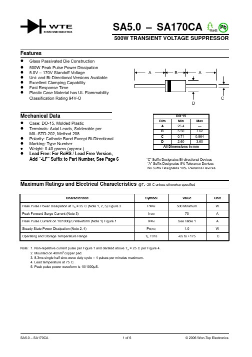
1000
VRWM, REVERSE STANDOFF VOLTAGE (V) Fig. 2 Typical Junction Capacitance
PP, PEAK PULSE POWER (kW)
1.0
0.1
TC = 25°C
0.1
1.0
54.00 54.00 58.00 58.00
60.00 60.00 64.00 64.00
70.00 70.00 75.00 75.00
78.00 78.00 85.00 85.00
90.00 90.00 100.00 100.00
110.00 110.00 120.00 120.00
130.00 130.00 150.00 150.00
元器件交易网
WTE
POWER SEMICONDUCTORS
SA5.0 – SA170CA Pb
500W TRANSIENT VOLTAGE SUPPRESSOR
Features
! Glass Passivated Die Construction
! 500W Peak Pulse Power Dissipation ! 5.0V – 170V Standoff Voltage ! Uni- and Bi-Directional Versions Available ! Excellent Clamping Capability ! Fast Response Time ! Plastic Case Material has UL Flammability
© 2006 Won-Top Electronics
元器件交易网
UNI-DIRECTIONAL 500 WATT AXIAL LEAD TVS
SMCJ40CA中文资料
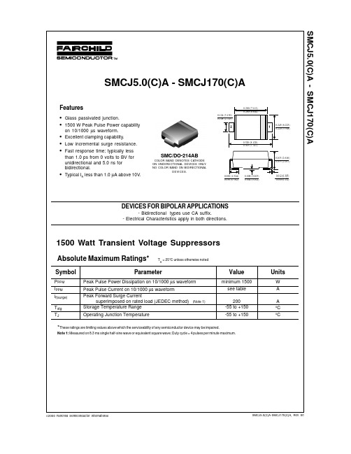
10 10 10 10 1 1 1 1 1 1 1 1 1 1 1 1 1 1 1 1 1 1 1 1 1 1 1 1 1 1 1 1 1 1 1 1 1 1 1 1 1 1 1 1 1 1
9.2 10.3 11.2 12.0 12.9 13.6 14.4 15.4 17.0 18.2 19.9 21.5 23.2 24.4 26.0 27.6 29.2 32.4 35.5 38.9 42.1 45.4 48.4 53.3 58.1 64.5 69.4 72.7 77.4 82.4 87.1 93.6 96.8 103.0 113.0 121.0 126.0 137.0 146.0 162.0 177.0 193.0 209.0 243.0 259.0 275.0
7.0 7.37 7.98 8.60 9.21 9.83 10.4 11.1 12.3 13.5 14.7 15.9 17.2 18.5 19.7 20.9 22.1 24.5 26.9 29.5 31.9 34.4 36.8 40.6 44.2 49.1 52.8 55.3 58.9 62.7 66.3 71.2 73.7 78.6 86.0 92.1 95.8 104.0 111.1 123.0 135.0 147.0 159.0 185.0 197.0 209.0
1500 Watt Transient Voltage Suppressors
Absolute Maximum Ratings*
Symbol
PPPM IPPM if(surge) Tstg TJ
TA = 25°C unless otherwise noted
Parameter
Peak Pulse Power Dissipation on 10/1000 µs waveform Peak Pulse Current on 10/1000 µs waveform Peak Forward Surge Current superimposed on rated load (JEDEC method) Storage Temperature Range Operating Junction Temperature
数码彩色多功能机 ApeosPort-IV C5570 C4470 C3370 C2270 说明书

禁止复制请注意法律禁止以下产品的复制:国内及海外银行发行的纸币与硬币,政府发行的有价证券,国家及地方债券票据,未使用的邮票与明信片,法律保护的证明贴纸。
禁止有版权产品的复制 (书籍、音乐、绘画、雕刻、地图、电影、摄影,等等),除了私人用途及在家或在上述限定范围内。
本产品安装有防伪功能。
该功能并非用于防止非法复制。
请务必仔细管理您的设备。
为了您的安全使用使用前请认真阅读产品手册。
应使用合适的电源及电压。
请确保机器接地以避免故障或短路可能会引起的触电。
北京 北京市朝阳区建国路甲92号世茂大厦904室 电话:010-********上海 上海市淮海中路300号香港新世界大厦29F/30F/32F 电话:021-********广州 广州市东风中路410-412号健力宝大厦15楼 电话:020-********深圳 深圳市福田区益田路4068号卓越时代广场32楼01~08、10室 电话:0755-********成都 成都市锦江区滨江东路9号B 座香格里拉中心办公楼6层 电话:028-********沈阳 沈阳市和平区和平南大街2号东宇大厦1305,1306室 电话:024-********天津 天津市南京路75号国际大厦502室 电话:022-********长春 长春市南关区亚泰大街3218号通钢国际大厦A 座21层01室 电话:0431-********青岛 青岛市香港中路61号阳光大厦A 座30层EH 电话:0532-********/69大连 大连市西岗区中山路147号森茂大厦1202E 电话:0411-********/80哈尔滨 哈尔滨市南岗区民益街76号网通广场20楼 电话:0451-********杭州 杭州市潮王路240号银地大厦一层 电话:0571-********武汉 武汉市建设大道568号新世界国贸大厦I 座21层2105-2107室 电话:027-********长沙 长沙市芙蓉区燕山路鸿飞大厦1208,1209号 电话:0731-*******郑州 郑州市中原中路220号裕达国际贸易中心A 座22层2212 电话:0371-********温州 温州市车站大道高联大厦9B3 电话:0577-********合肥 合肥市淮河路303号安徽邮电大厦11层D 座2号 电话:0551-*******南京 南京市汉中路89号金鹰国际商城21层B2-C1座 电话:025-********常州 常州市延陵西路23、25、27、29号投资广场17层1706单元 电话:0519-********无锡 无锡市中山路343号东方广场商务楼11层GH 座 电话:0510-********苏州 苏州市苏州工业园区苏华路2号国际大厦1610单元 电话:0512-********东莞 东莞市南城区元美路8号华凯广场B 座1712 电话:0769-********厦门 厦门市思明区湖东路6号华龙大厦805室 电话:0592-*******福州 福州市五四路国贸广场29楼C1 电话:0591-********西安 西安市南关正街88号长安国际广场B 座1006室 电话:029-********重庆 重庆市渝中区邹容路68号大都会商厦2301室 电话:023-********昆明 昆明市北京路155号附1号红塔大厦1201室 电话:0871-*******乌鲁木齐 乌鲁木齐市中山路86号中泉广场13楼B 座 电话:0991-*******富士施乐在华分支机构富士施乐全国服务热线:800-820-5146 400-820-5146/ApeosPort-IV C5570C4470C3370C2270ApeosPort-IVC5570/C4470/C3370/C2270数码彩色多功能机色彩革命ApeosPort-IV C5570 / C4470 / C3370 / C2270系列规格复印功能AP-IV C5570 AP-IV C4470 AP-IV C3370 AP-IV C2270类型稿台型内存1,5 GB(最大2 GB)硬盘80 GB(可用空间:40 GB)预热时间28 秒以下(室温20。
rs232保护电路

rs232保护电路RS232接⼝保护⽅案●RS232⼝在通信设备上作为调试⽤接⼝,板间通信接⼝和监控信号接⼝,传输距离不超过15⽶。
调试⽤接⼝使⽤⽐较频繁,经常带电插拔,因此接⼝会收到过电压,过电流的冲击,若不进⾏保护,很容易将接⼝芯⽚损坏。
●RS232的接⼝芯⽚输出电压⼀般为±9V,不会超过±12V。
因此对接⼝收发信号线可采⽤双向瞬态抑制⼆极管. BS0150MS,限流电阻选100欧姆,⼀般放在232接⼝芯⽚侧,电阻的功率要选⼤些,1/4W以上,否则电阻容易烧坏。
BS0150MS 器件50A(8/20uS)15A(10/1000uS)寄⽣电容15pF。
MAX232芯⽚的RS232接⼝保护电路 2009-03-14 18:16:17最近设计的⼀款仪表⾥使⽤RS232通讯,我⽤的是贴⽚“MAX232 ESE+ 0815”芯⽚,电路如下图:在选择TVS管的时候花费了点时间,开始时D1、D2打算使⽤,后来在同事的提醒下查了些资料。
⽤⽰波器观察MAX232的TXD出来的电压峰值不会超过10V,使⽤D2选⽤了;仔细查看MAX232的PDF,发现RXD输⼊端可以承受30V的电压,再加上有些芯⽚出来的RS232信号电平有可能超过20V,所以为了更⼤的兼容性D1就⽤了。
由于仪表所处的地⽅经常会有瞬间100~200v的⼤电压,R1,R2的作⽤在于限流,防⽌TVS管和⾃恢复保险丝的损坏。
不过R1 R2需要选择功率⼤些的,由于空间⾜够,所以我⽤的是1W的。
由于仪表⼯作环境没有连接市电以及任何天线,所以没有考虑防雷,如果要加防雷的话可以在前级再加陶瓷放电管。
有⼀点⼩疑问,我⽤⽰波器看得TXD出来的电压只在+7~-7V间,会不会是max232芯⽚质量不好,或者是假冒的或者是泵升电容质量不好不过信号传输倒也不影响,因为⼀般的芯⽚只要电压绝对值⼤于2V就可识别。
另外我做了个有意思的测试,在去掉tvs管保护的前提下。
Diotec 电子件 - 电信产品说明书

Diotec Produktefür TelekommunikationTypische Applikationen:Mobilteile, Ladegeräte, Modems, Schnittstellen, Stromversorgung, AusrüstungMobilteile Î SMD Schottky DiodenLadegeräte Î Brückengleichrichter: MiniDIL, MicroDILDC/DC-Wandler Î Schottky Dioden, Superschnelle-/Ultraschnelle-GleichrichterSchutzelemente Î TVS-Dioden, SDA2/4AK (Low Cj), (Schnelle) BrückengleichrichterSpannungsregelung Î Zener DiodenOR-ing Dioden Î Schottky Dioden, StandardGleichrichterMobilteileSchottky Dioden als VerpolungsschutzEingesetzt zwischen dem Akku des Mobilteiles und den Kontakten zum externen Ladegerät verhindern diese ein unerwünschtes Entladen bei versehentlich kurzgeschlossenen Kontakten und bieten Schutz gegen Laden mit falscher Polarität. Der niedrige Spannungsabfall an der Schottky-Diode sorgt für niedrige Ladeverluste. Die SGL34 und SGL1 in MiniMELF zeichnen sich durch geringen Platzbedarf auf der Leiterplatte aus.Typen1SMD: SGL34-20…100, SGL1-20…100, SMS120…1100, SMS220…2100, SMS320…3100;SK12…110, SK32SMA…310SMA, SK52…510, SK82…810;(0.5 bis 8 A!)1Vorzugstypen sind fettgedruckt; Farben entsprechend dem Diotec Selection Guide. Datenblätter siehe , …Produkte“.Ladegeräte / DC-DC WandlerÜberspannungsschutz: TVS-Dioden /Zenerdioden 1TGL34-… , TGL41-…, P4SMA…, P6SMB…, 1.5SMC…; (150 bis 1500 W Impuls; bis zu 550 V!) ZMM…, ZMD…, ZMY..., SMZ1..., SZ3C…, Z1SMA…, Z2SMB…, Z3SMC…; (0.5 bis 3 W dauernd)Eingangsgleichrichtung: Brückengleichrichter 10.5 bis 2 ASMD: MYS40…380, MS40…500, S40…500, B40…500S , B 40…380F S (s c h n e l l ), CS10…50S (Schottky) Durchsteckmontage: B40…500D , B 40…380F D (s c h n e l l ), CS10…50D (Schottky), B40…500R (rund)Spannungsbegrenzung: TVS-/S c h n e l l e -Diode 1TGL34-… , TGL41-…, P4SMAJ…, P6SMBJ…, 1.5SMCJ…; (150 bis 1500 W Impuls; bis zu 550 V!) R G L 34…, R G L 1…, S A 154…160, F R 1…, F R 2…, F R 3…; (0.5 b i s 3 A )Ausgangsgleichrichtung: Schottky Dioden 1SGL34-20…100, SGL1-20…100, SMS120…1100, SMS220…2100, SMS320…3100; SK12…110, SK32SMA…310SMA, SK52…510, SK82…810; (0.5 bis 8 A!)1Vorzugstypen sind fettgedruckt ; Farben entsprechend dem Diotec Selection Guide. Datenblätter siehe ,…Produkte“. Weitere Informationen in der Applikationsschrift “Diotec Produkte für Stromversorgungen”. Neben den hier gezeigten Bauteilen in SMD-Technik (zur Platz- und Gewichtsreduzierung) sind auch äquivalente Typen in axialer Bauform erhältlich.~~Blitzstromableitung in Telekom-AnwendungenTRBrückengleichrichter sind in Telekom-Anwendungen weit verbreitet, z. B. in analogen Verbindungskarten, Endgeräten (Telefonen, Modems, Fax- und Nebenstellengeräten), sowie für die Hochgeschwindigkeits-Übertragung über ADSL, SHDSL, ISDN oder E1/T1. Sie werden als Ableitungselemente eingesetzt oder für den gemeinsamen Schutz von Mehrfachleitungen.Empfohlene Produkte1:PlatzsparendMYS40, MS40– Sparen Platz auf Karten mit Mehrfacheingängen (Gehäuse nur 3x3 mm²!)Standard BrückengleichrichterS40, B40S– Für StandardlösungenSchnelle BrückenS40F,B40F S– bieten den Vorteil einer schnelleren Erholzeit während des Einschalt-Überschwingens und reduzieren somit die durchgelassene VerlustenergieSchottky BrückenCS30S, CS50S– Schottky Brücken begrenzen mit niedrigster Durchlass-Spannung1Farben entsprechend dem Diotec Selection Guide. Datenblätter siehe , …Produkte“. Neben den hier gezeigten Bauteilen in SMD-Technik (zur Platz- und Gewichtsreduzierung) sind auch äquivalente Typen in axialer Bauform erhältlich.Schutz von DatenleitungenTVS-DiodenErhältlich in uni- und bidirektionaler Ausführung (Suffix “C” bzw. “B” bei der BZW-Reihe). Bidirektionale Typen bieten Schutz gegen positive und negative Spannungsspitzen.Dimensionierung: die maximal auftretende Signalspannung sollte die Sperrspannung V WM des Bauteils nicht überschreiten. Bei einem maximalen Strom I PPM und einer 10/1000 µs Pulsform (siehe Datenblatt) beträgt die maximale Klemmspannung V C. Die zu schützenden Ein- bzw. Ausgänge sollten mindestens diese Spannung aushalten können.Typen1Bedrahtet: BZW04-…, P4KE…, BZW06-…, P6KE…, 1.5KE… , 5KP…; (400 bis 5000 W; bis zu 520 V!) SMD:TGL34-… , SDA2/4AK, TGL41-…, P4SMA…, P6SMB…, 1.5SMC… ; (150 bis 1500 W; bis zu 550 V!)SDA2/4AK Reihe: niederkapazitiver SchutzBei den SDA2AK bzw. SDA4AK handelt es sich um spezielle Schutz-Dioden. Sie bestehen aus antiparallel geschalteten Standardgleichrichtern in einem einzelnen MELF (DO-213AB) Gehäuse (siehe unten). Hierdurch wird eine nominale Klemmspannung von 1 bzw. 2 V erreicht, bei Impulströmen von bis zu 40 A. Auf Anfrage sind auch andere Klemmspannungen erhältlich.Die resultierende Kapazität liegt im unteren pF-Bereich, was die Verwendung bei sehr hohen Signal-Frequenzen zulässt. Darüber hinaus können diese Bauteile in Reihe zu anderen Schutzelementen geschaltet werden, um deren Kapazität auf extrem niedrige Werte zu reduzieren.SDA4AK SDA2AK1Vorzugstypen sind fettgedruckt; Farben entsprechend dem Diotec Selection Guide. Datenblätter siehe , …Produkte“.SpannungsregelungZenerdioden zur einfachen SpannungsregelungEine einfache Methode um stabile Gleichspannungen aus einer ungeregelten Quelle zu erzeugen. Der Vorwiderstand muss so gewählt werden, dass der maximal zulässige Zenerstrom I Zmax (siehe Datenblatt) bei maximaler Eingngasspannung und Leerlauf am Ausgang nicht überschritten wird. Besteht dieSpannungsquelle aus einem Transformator, so ist evtl. der Serienwiderstand der Windungen ausreichend als Vorwiderstand. Sollte die Verlustleistung eines einzelnen Bauteils zu gering sein, so können zur Leistungserhöhung zwei oder mehr in Reihe geschaltet werden. Die Toleranz ist gestuft entsprechend dem E24 Standard (ungefähr +/- 5%); falls engere Grenzen benötigt werden sind auf Anfrage Bauteile mit +/- 2% Toleranz erhältlich.Typen 1Bedrahtet: ZPD…, ZPY…, ZY…, 3EZ…, 1N53..B ; (0.5 bis 5 W)SMD: BZX84C…, 2BZX84C…, ZMM…, ZMD…, ZMY..., SMZ1..., SZ3C…, Z1SMA, Z2SMB…, Z3SMC…; (0.2 bis 3 W)Zuverlässiger Betrieb auch bei Gewitter …Kleinsignal-Zenerdioden wie die ZPD/ZMM oder BZX84 sind mit kleinflächigen, planaren Chipsaufgebaut. Deren Kontaktierung erfolgt entweder durch Druckkontakt (ZPD/ZMM im Glasgehäuse) oder durch Drahtbonden (BZX84). Sie bieten eine preiswerte Möglichkeit der Spannungsstabilisierung, sind aber empfindlicher gegen Überspannungen durch Blitzschlag etc. (ein gewisser Anteil der Energie eines Blitzschlags wird immer den Primär- und Sekundärschutz überwinden!). Leistungs-Zenerdioden wie die ZY, Z1SMA, ZMD etc. sind mit robusten, nichtplanaren Zenerchips großer Fläche aufgebaut, dieKontaktierung erfolgt durch leistungsfähige Lötverbindungen. Damit sind sie die bevorzugte Lösung für hochzuverlässige Schaltungen.1Vorzugstypen sind fettgedruckt ; Farben entsprechend dem Diotec Selection Guide. Datenblätter siehe , …Produkte“.Ungeregelte Gleichspannung GeregelteGleichspannungOR-ing DiodenEntkopplung von Spannungsquellen: Standard oder Schottky Dioden Wenn die Verluste niedrig sein sollen und die Gleichspannung unter 100 V liegt können Schottky Dioden eingesetzt werden. Spezielle Dioden (auf Anfrage) bieten neben niedrigem Durchlass auch geringe Sperrströme. Standard Dioden eignen sich für höhere Spannungen, bei Hochstromanwendungen ist die Verwendung von Bauteilen im Press-fit Gehäuse zu empfehlen. Die D30V.. Reihe beinhaltet Standard-Dioden mit gemeinsamer Kathode in einem quadratischen Brückengehäuse.Types1Bedrahtet: 1N4001…7, 1N5391…99, 1N5400K…08K, 1N5400…08, BY251…55, BY550-…, P600…,P1000…, P1200…;(1 bis 12 A)SB120…1100, SB220…2100, SB320…3100, SB520…5100, SB820…8100;(1 bis 8 A) SMD: G L34…, GL1…,SM4001…7, SM5059…63, SM5400…08,S1…, S2…, S3…, S5…; (0.5 bis 5 A) SMS120…1100, SMS220…2100, SMS32…310; SK12…110, SK32SMA…310SMA, SK52…510;SK82…810 (1 bis 8 A!)Press-fit: B YP25…, BYP35…, BYP60…, KYW25…, KYW35…, KYZ25…, KYZ35…; (25 bis 60 A) Qudratisch mit Fast-on- oder Drahtanschlüssen: D30VC20…80; (2x15 A)。
Schneider Electric LT3SM00M PTC 触摸式重置型纤维电路保护器数据表说明
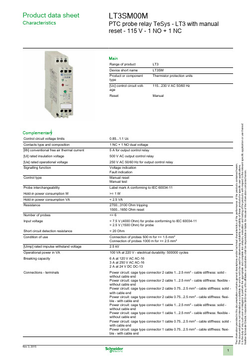
T h e i n f o r m a t i o n p r o v i d e d i n t h i s d o c u m e n t a t i o n c o n t a i n s g e n e r a l d e s c r i p t i o n s a n d /o r t e c h n i c a l c h a r a c t e r i s t i c s o f t h e p e r f o r m a n c e o f t h e p r o d u c t s c o n t a i n e d h e r e i n .T h i s d o c u m e n t a t i o n i s n o t i n t e n d e d a s a s u b s t i t u t e f o r a n d i s n o t t o b e u s e d f o r d e t e r m i n i n g s u i t a b i l i t y o r r e l i a b i l i t y o f t h e s e p r o d u c t s f o r s p e c i f i c u s e r a p p l i c a t i o n s .I t i s t h e d u t y o f a n y s u c h u s e r o r i n t e g r a t o r t o p e r f o r m t h e a p p r o p r i a t e a n d c o m p l e t e r i s k a n a l y s i s , e v a l u a t i o n a n d t e s t i n g o f t h e p r o d u c t s w i t h r e s p e c t t o t h e r e l e v a n t s p e c i f i c a p p l i c a t i o n o r u s e t h e r e o f .N e i t h e r S c h n e i d e r E l e c t r i c I n d u s t r i e s S A S n o r a n y o f i t s a f f i l i a t e s o r s u b s i d i a r i e s s h a l l b e r e s p o n s i b l e o r l i a b l e f o r m i s u s e o f t h e i n f o r m a t i o n c o n t a i n e d h e r e i n .Product data sheetCharacteristicsLT3SM00MPTC probe relay TeSys - LT3 with manualreset - 115 V - 1 NO + 1 NCMainRange of product LT3Device short name LT3SMProduct or component typeThermistor protection units [Uc] control circuit volt-age 115...230 V AC 50/60 Hz ResetManualComplementaryControl circuit voltage limits 0.85...1.1 UcContacts type and composition1 NC + 1 NO dual voltage [Ith] conventional free air thermal current 5 A for output control relay [Ui] rated insulation voltage 500 V AC output control relay[Ue] rated operational voltage 250 V AC 50/60 Hz for output control relay Signalling function Voltage indication Fault indication Control typeManual reset Manual testProbe interchangeability Label mark A conforming to IEC 60034-11Hold-in power consumption W >= 1 W Hold-in power consumption VA < 2.5 VAResistance 2700...3100 Ohm tripping 1500...1650 Ohm reset Number of probes <= 6Input voltage< 7.5 V (4000 Ohm) for probe conforming to IEC 60034-11< 2.5 V (1500 Ohm) for probe Short circuit detection resistance < 20 OhmCondition of useConnection of probes 500 m for >= 1.5 mm²Connection of probes 1000 m for >= 2.5 mm²[Uimp] rated impulse withstand voltage 2.5 kVOperational power in VA 100 VA at 220 V - electrical durability: 500000 cycles Breaking capacity6 A at 120 V AC AC-163 A at 250 V AC AC-162 A at 24 V DC DC-13Connections - terminalsPower circuit: cage type connector 2 cable 1...2.5 mm² - cable stiffness: solid -without cable endPower circuit: cage type connector 2 cable 1...2.5 mm² - cable stiffness: flexible -without cable endPower circuit: cage type connector 2 cable 0.75...2.5 mm² - cable stiffness: solid -with cable endPower circuit: cage type connector 2 cable 0.75...2.5 mm² - cable stiffness: flexi-ble - with cable endPower circuit: cage type connector 1 cable 1...2.5 mm² - cable stiffness: solid -without cable endPower circuit: cage type connector 1 cable 1...2.5 mm² - cable stiffness: flexible -without cable endPower circuit: cage type connector 1 cable 0.75...2.5 mm² - cable stiffness: solid -with cable endPower circuit: cage type connector 1 cable 0.75...2.5 mm² - cable stiffness: flexi-ble - with cable endTightening torque0.8 N.mHeight100 mmWidth22.5 mmDepth100 mmProduct weight0.22 kgEnvironmentStandards IEC 60034-11VDE 0660Product certifications LROS (Lloyds register of shipping)IP degree of protection IP20 conforming to VDE 0106IP20 conforming to IEC 60529Ambient air temperature for operation-25...60 °CAmbient air temperature for storage-40...85 °C conforming to IEC 60068-2-2-40...85 °C conforming to IEC 60068-2-1Operating altitude> 1500...3000 m with derating in temperature<= 1500 m without derating in temperatureVibration resistance 2.5 gn 2...25 Hz conforming to IEC 60068-2-61 gn 25...150 Hz conforming to IEC 60068-2-6Shock resistance 5 gn 11 ms conforming to IEC 60068-2-27Electromagnetic compatibility Susceptibility to electromagnetic fields - test level level 3 conforming to IEC61000-4-3Surge resistance 1.2/50-8/20 - test level level 4 conforming to IEC 61000-4-5Resistance to fast transient - test level level 3 conforming to IEC 61000-4-4Resistance to electrostatic discharge - test level level 3 conforming to IEC61000-4-2Immunity to microbreaks and voltage drops conforming to IEC 61000-4-11 Contractual warrantyPeriod18 months。
220C中文说明书
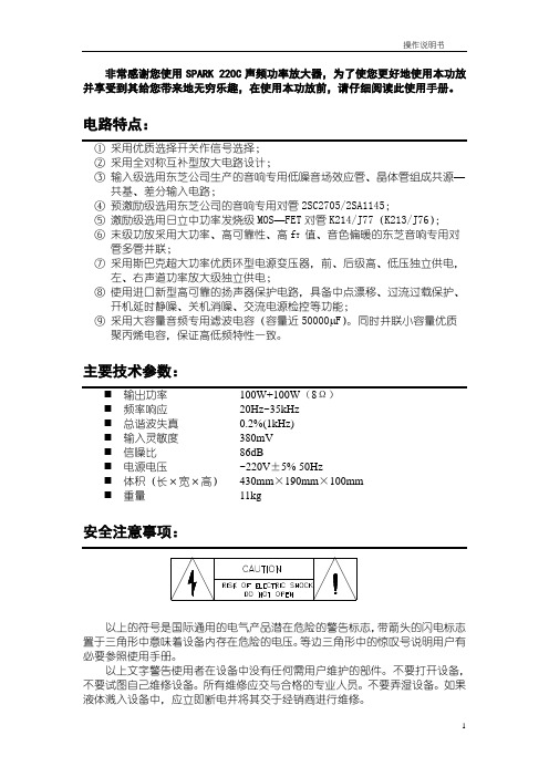
非常感谢您使用SPARK 220C声频功率放大器,为了使您更好地使用本功放并享受到其给您带来地无穷乐趣,在使用本功放前,请仔细阅读此使用手册。
电路特点:①采用优质选择开关作信号选择;②采用全对称互补型放大电路设计;③输入级选用东芝公司生产的音响专用低噪音场效应管、晶体管组成共源—共基、差分输入电路;④预激励级选用东芝公司的音响专用对管2SC2705/2SA1145;⑤激励级选用日立中功率发烧级MOS—FET对管K214/J77(K213/J76);⑥末级功放采用大功率、高可靠性、高f T值、音色偏暖的东芝音响专用对管多管并联;⑦采用斯巴克超大功率优质环型电源变压器,前、后级高、低压独立供电,左、右声道功率放大级独立供电;⑧使用进口新型高可靠的扬声器保护电路,具备中点漂移、过流过载保护、开机延时静噪、关机消噪、交流电源检控等功能;⑨采用大容量音频专用滤波电容(容量近50000 F)。
同时并联小容量优质聚丙烯电容,保证高低频特性一致。
主要技术参数:⏹频率响应20Hz~35kHz⏹总谐波失真0.2%(1kHz)⏹输入灵敏度380mV⏹信噪比86dB⏹电源电压~220V±5% 50Hz⏹体积(长×宽×高)430mm×190mm×100mm⏹重量11kg置于三角形中意味着设备内存在危险的电压。
等边三角形中的惊叹号说明用户有必要参照使用手册。
以上文字警告使用者在设备中没有任何需用户维护的部件。
不要打开设备,不要试图自己维修设备。
所有维修应交与合格的专业人员。
不要弄湿设备。
如果液体溅入设备中,应立即断电并将其交于经销商进行维修。
保修2.为使保修生效,客户必须在购买本机两周内将填好的保修卡交于经销商或寄回珠海斯巴克电子设备有限公司。
3.在责任期限内,本公司保证产品在正常使用下出现的质量问题的维修,条件是该产品得到返修许可并运到保修单位或运回珠海斯巴克电子设备有限公司。
T40S 无线 PLC 产品说明书

--V1.4T40S 短信/GPRS 信道-无线PLC DESCRIPITION OF PRODUCTS北京捷麦顺驰科技有限公司 ***************目录1.概述 (5)1.1 捷麦PLC概述 (5)1.2 产品系列介绍 (5)1.3 T40S产品概述 (8)2.外观尺寸及指标 (9)2.1 外观及说明 (9)2.2 内部等效逻辑图 (9)2.3 端子接口说明 (10)2.4 LED指示灯 (10)2.5 技术指标 (11)2.6 安装方法 (12)2.7 SIM卡安装 (12)3.IO口功能 (13)3.1 特性 (13)3.2 输入接线示意图 (13)3.3 输出接线说明 (14)3.4 IO输入档位选择 (15)3.5 上电初始输出状态 (16)3.6 滤波参数设置 (16)3.6.1 数字量滤波器 (16)3.6.2 模拟量滤波器 (18)3.7 IO口的采集与控制 (19)4.用户编程 (19)4.1 编程连接 (20)4.2 PLC编程软件开发环境 (21)24.3.1 主界面 (22)4.3.2 编程资源 (22)4.4 C语言编程 (23)4.4.1 主界面 (23)4.4.2 编程资源 (23)5.通信 (25)5.1 串口通信 (25)5.1.1 收发数据 (25)5.1.2 参数及设置 (26)5.1.3 串口电平转换 (27)5.2 GPRS通信 (29)5.2.1 通信模型 (29)5.2.2 收发数据 (30)5.2.3 参数及设置 (31)5.3 短信通信 (34)5.3.1 收发数据 (34)5.3.2 参数及设置 (35)6.组建主从测控网络 (35)6.1 主从网的基本概念与架构 (35)6.2 主站的构成 (37)6.2.1 计算机做主站 (37)6.2.2 用户主站设备做主站 (37)6.2.3 PLC做主站 (38)6.3 PLC做分站 (41)7.组建主从测控网络 (42)7.1 主从网的基本概念与架构 (42)7.2 主站的构成 (43)37.2.2 用户主站设备做主站 (44)7.2.3 PLC做主站 (44)7.3 PLC做分站 (47)7.4 工程实例 (48)7.4.1 项目需求 (48)7.4.2 方案选择 (48)7.4.3 参数设置 (48)7.4.4 程序设计 (50)8.附录 (54)8.1 相关文档及阅读指南 (54)8.2 版权声明 (55)8.3 免责声明 (55)8.4 技术支持 (55)41. 概述1.1 捷麦PLC概述捷麦无线PLC专用于远程测控系统。
施耐德 APC SMV Series 750 1000 1500 2000 3000 VA说明书
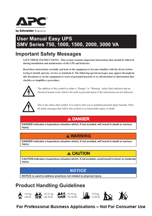
SA VE THESE INSTRUCTIONS - This section contains important instructions that should be followed during installation and maintenance of the UPS and batteries.Read these instructions carefully and look at the equipment to become familiar with the device before trying to install, operate, service or maintain it. The following special messages may appear throughout this document or on the equipment to warn of potential hazards or to call attention to information that clarifies or simplifies a procedure.The addition of this symbol to either a “Danger” or “Warning” safety label indicates that an electrical hazard exists which will result in personal injury if the instructions are not followed.This is the safety alert symbol. It is used to alert you to potential personal injury hazards. Obey all safety messages that follow this symbol to avoid possible injury or death.NOTICE is used to address practices not related to physical injury.Important Safety Messages<18 kg <40 lb18-32 kg >55 kg >120 lb32-55 kg 70-120 lbProduct Handling Guidelines40-70 lbNOTICEFor Professional Business Applications – Not For Consumer UseEasy UPS SMV Series 750, 1000, 1500, 2000, 3000VA2ŸAdhere to all national and local electrical codes.ŸThis UPS is intended for indoor use only. To prevent the risk of fire or electric shock, install in atemperature and humidity controlled indoor area, free of conductive contaminants.ŸMains socket outlet that supplies the UPS shall be installed near the UPS and shall be easily accessible.ŸUPS must be connected to an earthed mains socket outlet.ŸCAUTION This UPS is designed to satisfy all of requirement of PCs only.ŸCAUTION Risk of electric shock, do not remove the chassis cover. Servicing should be performed by Qualified Engineer.ŸServicing of user replaceable batteries should be performed or supervised by personnelknowledgeable about batteries and required precautions. In this case batteries are not user replaceable.ŸWhen replacing battery the UPS must be OFF, and its AC inlet unplugged.ŸCAUTION Do not dispose of batteries in a fire. The batteries may explode.ŸCAUTION Risk of explosion if battery is replaced by an incorrect type. Dispose of used batteries according to the instructions.ŸDo not open or mutilate batteries. They contain an electrolyte that is toxic and harmful to the skin and eyes.ŸCAUTION A battery can present a risk of electrical shock and high short circuit current. The following precautions should be observed when working on batteries.a. Remove watches, rings or other metal objects.b. Use tools with insulated handles.c. Wear rubber gloves and boots.d. Do not lay tools or metal parts on top of batteries.e. Disconnect the charging source prior to connecting or disconnecting battery terminals.f. Determine if battery is inadvertently grounded. If inadvertently grounded, remove source from ground. Contact with any part of a grounded battery can result in electrical shock. The likelihood of such shock can be reduced if such grounds are removed during installation and maintenance.Safety and General InformationGeneral safetyBattery safetyŸCAUTION The UPS contains internal batteries and may present a shock hazard even whendisconnected from AC power.ŸCAUTION Risk of electric shock, Battery Circuit is not isolated from AC input, hazardous voltage may exist between battery terminals and ground. Test before touching.Radio Frequency WarningThis is a category C2 UPS product. In a residential environment, this product may cause radio interference, in which case the user may be required to take additional measures.InventorySoftware, User documentation3a)IEC C14 plug to C13 plugc)SCHUKO plug to IEC C19 plugb)SCHUKO plug to IEC C13 plugModel SMV750CAI SMV1000CAI SMV1500CAI SMV2000CAI Cable a x 1b x 1SMV3000CAIa x 1c x 1USB cableEasy UPS SMV Series 750, 1000, 1500, 2000, 3000VAOptionalProduct FeaturesON/OFF button RS-232USB portFan /ventilation hole Battery connector AC Inlet4FuseBattery backup outlets with surge protection Output breaker (only for SMV3000CAI)Intelligent Slot Dry contactEasy UPS SMV Series 750, 1000, 1500, 2000, 3000VAFront panel display5Easy UPS SMV Series 750, 1000, 1500, 2000, 3000VA1. Inspection:Ÿ UPS MUST be installed indoor with controlled environment free of excessive dust, corrosive air or conductive dust.Ÿ Do NOT install in outdoor.Ÿ Keep out of direct sun light, water and heat sources Ÿ Place the unit on the stable floor.2. Connect the battery by pulling the battery handle up, and then pushing it into the unit.Ÿ The battery connector is located on the rear panel.-Connect prior to operation.-Disconnect prior to transportation. Turn OFF the UPS and remove input power cable before disconnecting the battery connector.3.Connect equipment to the UPS. Avoid using extension cords. ŸDo NOT connect printers, heaters, or copiers to the UPS.ŸDuring a power outage or other AC problems, the Battery Backup outlets receive power for a limited time from the Easy UPS.4. Plug the Easy UPS power cord directly into a wall outlet, not into a surge protector or power strip.5 Press the ON/OFF button to turn on the unit..ŸThe Easy UPS should charge the battery for at least 8 hours to ensure sufficient runtime.Ÿ Press On / OFF button in 1~3 seconds. The buzzer sound confirms that the Easy UPS is on and provide power to outlets.6 Cold start the UPS.ŸUse cold start feature to supply power to connected equipment from the UPS batteries when the UPS is off and there is no power utility.7 Connect and install management software.ŸEasy UPS is provided with management software for unattended operating system shutdown, UPS monitoring, and UPS settings.ŸRefer to for more information.8When UPS is operating in one of three conditions shown as below, the dry contact interface will be . activated. The diagram is shown in Pic.1.ŸWhen UPS detects the battery failure, PIN1-4 of a dry contact will be activated. ŸWhen UPS is operating in Backup mode , PIN2-4 of a dry contact will be activated.ŸWhen UPS is operating in AC mode ,.PIN3-4 of a dry contact will be activatedWhen UPS is operating in…Activate1. AC modePIN3-42. Backup modePIN2-43. Standby modeN/A4. AC mode and Battery weakPIN1-4 & PIN3-45. Standby mode and Battery weakPIN1-4(Pic. 1)Before installing the UPS, ensure the input breaker on the UPS upstream is Type C rated at 16A.Installation and Power OnAudible Indicators and Status IconsIf the Easy UPS…Possible cause...Beeps every 2 seconds.Easy UPS is running on battery. You should consider saving any work in progress.Continuous Beeping.Low battery condition and battery run-time is very low. Promptly save any work in progress, exit all open applications, and shut down the operating system.Continuous tone with illuminated.Battery Backup outputs are overloaded.Continuous tone with illuminated.a. Press ON/OFF button for 1-3 seconds to mute the alarm.b. Continuous tone will persist until battery LOW.(<11Vdc each BATT)Beeps every 4 seconds with illuminated.The battery is near the end of useful life or damaged.: Fan fault detected : Inverter short : Inverter over voltage6Easy UPS SMV Series 750, 1000, 1500, 2000, 3000VABatteryEnvironment V oltageUPS Capacity (total)Rated V oltage Transfer time ModelPhysicalWaveformType(maintenance-free)Net Weight (kg)Dimension (DxWxH, mm)Gross Weight (kg)Enclosure typeV oltage range SMV750CAI220/230/240V AC165~290Vac ±5Vac165~295Vac ±8Vac8A 8A12A 20A25A 230V ACTypical 2-6 ms, 12ms max.12V/7Ah x 212V/7Ah x 212V/10Ah x 212V/7Ah x 412V/9Ah x 4410 x 160 x 220455 x 180 x 240Less than 45 dBIP20Noise levelIP RatingSMV1000CAISMV1500CAISMV2000CAI SMV3000CAIFuseCharging time Packaging Dimension (DxWxH, mm)Operating temperature &Humidity750V A 1000V A 1500V A 2000V A 3000V A lead acidlead acid lead acid lead acidlead acid525W700W1050W 1400W2100WPure Sine Wave4-6 hours recover to 90% capacity 13.617.823.525.2508 x 272 x 339604 x 319 x 41416.620.7526.928.90-95 % RH @ 0-40°C (non-condensing)Frequency Range 45-65 Hz (auto sensing) ±1HzSpecificationsOutputInputTroubleshooting7 Easy UPS SMV Series 750, 1000, 1500, 2000, 3000VAIf the unit requires service, do not return it to the dealer. Follow these steps:1. Review the Troubleshooting section of the manual to eliminate common problems.2. If the problem persists, contact Schneider Electric IT (SEIT) Customer Support through the APC by Schneider Electric website, .a. Note the model number and serial number and the date of purchase. The model and serial numbers are located on the rear panel of the unit.b.Call SEIT Customer Support and a technician will attempt to solve the problem over the phone. If this is not possible, the technician will issue a Returned Material Authorization Number (RMA#).c. If the unit is under warranty, the repairs are free.d.Service procedures and returns may vary internationally. Refer to the APC by Schneider Electric website for country specific instructions.3. Pack the unit in the original packaging whenever possible to avoid damage in transit. Never use foam beads for packaging. Damage sustained in transit is not covered under warranty.4. Always DISCONNECT THE UPS BATTERIES before shipping. The United States Department of Transportation (DOT), and the International Air Transport Association (IATA) regulations require that UPS batteries be disconnected before shipping. The internal batteries may remain in the UPS.5. Write the RMA# provided by Customer Support on the outside of the package.6. Return the unit by insured, pre-paid carrier to the address provided by Customer SupportAPC by Schneider Electric IT Customer Support WorldwideWa rrantyRegister y our p roduct o n -line. h ttp ://wa r The standard warranty is two (2) years from the date of purchase. SEIT standard procedure is to replacethe original unit with a factory reconditioned unit. Customers who must have the original unit back due to the assignment of asset tags and set depreciation schedules must declare such a need at first contact with an SEIT Technical Support representative. SEIT will ship the replacement unit once the defective unit has been received by the repair department, or cross-ship upon the receipt of a valid credit card number. The customer pays for shipping the unit to SEIT. SEIT pays ground freight transportation costs to ship the replacement unit to the customer.For country specific customer support, go to the APC by Schneider Electric website, www .apc .com .EN 990-91267B05/2021© 2021 APC by Schneider Electric. APC, the APC logo are owned by Schneider Electric Industries S.A.S., or their affiliated companies. All other trademarks are property of their respective owners.Service。
Interpact INS负荷开关

INS160 INS250- INS250- INS250- INS250 INS320 INS400 INS500 INS630
100
160
200
160
100
160
200
250
320
400
500
630
750
750
750
750
750
750
750
750
750
8
8
8
8
8
8
8
8
8
... 最高工作电压
INS160 INS250- INS250- INS250- INS250 INS320 INS400 INS500 INS630
INS40 INS63 INS80 INS100 INS125
Ue AC22A 380/415 V 40
63
80
100
125
Ue AC22A 690 V
40
63
80
100
125
Ue AC23A 380/415 V 40
63
72
100
125
Ue AC23A 500/525 V 40
40
40
100
125
紧急断开负荷开关
这种负荷开关可以用作紧急断开装置。在这种应用中,它必须易于发现、触及并可 指示(见有关设备安全性的标准和规则 VDE 0660、VDE 0113、CNOMO 等)。 为了便于识别,紧急断路负荷开关使用标准规定的专门颜色,并且与标准型号的相 区别: b 设备的前面板用黄色 b 手柄用红色。 Interpact 紧急断开负荷开关的功能特性与标准型式相同。 紧急断开负荷开关可提供可靠接触指示。
TVS管选型

一.什么叫TVS瞬态抑制二极管?瞬态二极管(Transient Voltage Suppressor)简称TVS,是一种二极管形式的高效能保护器件。
当TVS二极管的两极受到反向瞬态高能量冲击时,它能以10的负12次方秒量级的速度,将其两极间的高阻抗变为低阻抗,吸收高达数千瓦的浪涌功率,使两极间的电压箝位于一个预定值,有效地保护电子线路中的精密元器件,免受各种浪涌脉冲的损坏。
二.如何选用雷茂电子公司生产的TVS瞬态抑制二极管?1.首先确定被保护电路的最大直流或连续工作电压。
S的反向变位电压即工作电压(V RWM)应大于或等于被保护电路的最大工作电压。
S的最大箝位电压(V C)应低于被保护电路的最大允许安全电压(最大承受电压)。
S额定瞬态脉冲功率PM应大于被保护电路可能出现的最大瞬态浪涌功率。
在确定了最大箝位电压(V C)后,其峰值脉冲电流应大于瞬态浪涌电流。
5.双向TVS用于交流电或来自正负双向脉冲的电路。
单向TVS一般用于电路只有正向电平信号(直流电路)。
6.对于数据接口电路的保护,需必须注意选取具有合适电容C的TVS器件。
7.温度考虑。
TVS可以在-55℃~+150℃之间工作。
如果应用电路中TVS在一个变化的温度工作,由于其反向漏电流ID是随增加而增大;功耗随TVS结温增加而下降,从+25℃~+175℃,大约线性下降50%,击穿电压VBR随温度的增加按一定的系数增加。
因此,需要查阅雷茂电子相关产品资料,考虑温度变化对其特性的影响。
三.雷茂TVS瞬态二极管有哪些系列?类别封装击穿电压值(A:单向,C A:双向)功率SMAJ系列(SMA/DO-214AC)(5.0A/CA-440A/C A)400WP4SMA系列(SMA/DO-214AC) (6.8A/CA-550A/CA) 400WSMBJ系列(SMB/DO-214AA)(5.0A/CA-440A/C A)600W贴片型P6SMB系列(SMB/DO-214AA)(6.8A/CA-550A /CA)600WSMCJ系列(SMC/DO-214AB)(5.0A/CA-440A/ CA)1500W1.5SMC系列(SMC/DO-214AB)(6.8A/CA-550A/ CA)1500WSMDJ系列(SMC/DO-214AB)(5.0A/CA-220A/ CA)3000W5.0SMD系列(SMC/DO-214AB)(11A/CA-170A /CA)5000W雷茂TVS管P4KE系列(DO-204AL/DO-41)(6.8A/CA-550 A/CA)400WSA系列(DO-204AC/DO-15)(5.0A/CA-220 A/CA)500WP6KE系列(DO-204AC/DO-15)(6.8A/CA-550 A/CA)600W1.5KE系列(DO-201)(6.8A/CA-550 A/CA)1500W3KP系列(P600)(5.0A/CA-220A/ CA)3000W插件型5KP系列(P600)(5.0A/CA-250 A/CA)5000W15KPA系列(P600)(17A/CA-28 0A/CA)15000W20KPA系列(P600)(20A/CA-300A /CA)20000W30KPA系列(P600)(28A/CA-288 A/CA)30000WSAC低电容系列(DO-204AC/DO-15)(5.0A-50 A)500W/50PFLCE低电容系列(DO-201)(6.5A-28A)1500W/100PF四.雷茂TVS瞬态抑制二极管主要适用于哪些产品?雷茂TVS瞬态抑制二极管目前已广泛应用于:计算机系统、通讯设备、交/直流电源、汽车电子、电子镇流器、家用电器、仪器仪表(电度表)、RS232/422/423/485、I/O、LAN、ISDN、ADSL、USB、MP3、PDAS、GPS、CDMA、GSM、数字照相机的保护、共模/差模保护、RF 耦合/IC 驱动接收保护、电机电磁波干扰抑制、声频/视频输入、传感器/变速器、工控回路、继电器、接触器噪音的抑制等各个领域。
西威变频器调试资料-中文版
liuzhanpeng2008-11-29 21:28 MP 电机保护装置(MPD) '@Y@H,VLC 电压检测(5V) Sj}@5 X6 CGRP/J 三相主电源故障(正常状态是点亮) ;/SM^&YES 急停 z1F[okLADOL 开门限位 ~-6Kl3YRSL 远程串行通讯线(正常状态是闪烁) (9$/r/-aBC 抱闸状态 abCcZ<=|bNOR/d 正常操作检验 D C mNxNINS 检修操作ES 急停 ;vF8V`fDW 厅门信号 2 ,;+)DFC 门完全关闭 OHqLMBW!!DOL 开门限位 7vcYI#(2 YDOB 开门按钮灭 r&xqsZ%RLV 轿厢位于门区内(DZ) 亮(只是门区之内) Yq#I# 2RDRSL 远程串行通讯线闪烁哎呀凡心2009-01-02 12:51 OH5000调试资料分享0LCBII用于sOH5000电梯 Gui[/iY,F对于OH5000电梯s系统,LCBII采用LSVF_W的控制方式,即速度采用V码输出,输入信号使用DS码。
Pv\8 \,B9OH5000电梯(s)调试 Odhr=HsSIEI变频器应用培训 Iij$ce`nx用服务器设置LSVF_W控制方式: ]gaeN2M1-3-1-4 Drive: 17; +KNd%AJ平层装置采用2个光电开关ULZ和DLZ fy|I32光电距离为6cm左右,平层隔光板长度25cm; X{6a光电信号通过LPB2转换后,分别送给LCBII和变频器,作为位置参考信号; BD86t[${W LCBII采用2个光电作为门区信号,因此要作如下设置:M1-3-1-6 DZ-TYP: 1~3f|-%ZLSVF_W:V码含义及转化 e-\/1N84LSVF_W:DS信号 AP1ZIc6硬件系统框图 :2C <;o驱动器及电机参数的设置/检查 b0@K ~O;g上电后首先检查STARTUP/Startup config/Setup mode中的Drive data和Motor data,参照右表。
MR-J3-22KA4-LC078 说明书
MR-J3-22KA4-LC078 说明书MR-J3-22KA4-LC078巴中伺服控制器JSDG2S-30A ECMA-C10602ES 1FK7042-5 AF71-1SG0四川伺服电机维修SGDH-15 AE-S MHMD012G1V 此时电机应该不动,而且可以用外力轻松转动,如果不是这样,检查使能信号的设置与接线用外力转动电机,检查控制卡是否可以正确检测到电机位置的变化,否则检查编码器信号的接线和设置折叠编辑本段产品分类安川电机是运动控制领域*的生产厂商,是日本*个做伺服电机的公司,其产品以稳定**著称,,是全球销售量大,使用行业多的伺服** 在国内,安川伺服多年来占据了大的市场份额安川伺服电机主要分Σ-Ⅰ,Σ-Ⅰ,Σ-Ⅰ,Σ-Ⅰ四大系列,目前Σ-Ⅰ和Σ-Ⅰ(除大容量以外)已停产Σ-Ⅰ系列在国内受众为广泛另有简易型伺服产品骏马系列折叠旋转型电机型号SGMJV(小容量/中惯量):100W~750W 特点(过载能力强、控制功能多、适合大多数通用场合);矢量控制方面与V500相当(工作于多种模式:速度、转矩、位置及各模式的切换、用途*广泛、**);外型结构和辅助功能与F700相同(通讯功能强、信号调整方面近似工业仪表的特点,调节余地大、使用*为方便) 发挥普通电机的佳性能(无传感器矢量控制):驱动无编码器的普通电机实现**和**度响应运行的矢量控制在0.3Hz的*低速下高可实现200%的输出转矩转矩模式下控制范围1:20;响应水平进一步提高, 速度响应120rad/s, 速度控制范围1:200 安川电机(中国)有限公司是安川电机在中国的总公司,前身为安川电机在上海市的销售子公司,与2011年向该子公司成立"安川电机(中国)有限公司" 总公司,统一管理位于上海、北京、辽宁省沈阳市的六家子公司,并在管理、销售、生产方面实现相互协作安川电机(中国)有限公司自创立以来,以*特的技术,为社会和公共事业作贡献以日本株式会社安川电机的创业精神为指导,为中国的各产业领域作出了贡献3、试方向对于一个闭环控制系统,如果反馈信号的方向不正确,MR-J3-22KA4-LC078巴中伺服控制器JSDG2S-30A ECMA-C10602ES 1FK7042-5 AF71-1SG0四川伺服电机维修SGDH-15 AE-S MHMD012G1V 130ST-M04025(1KW) 130ST-M05025(1.3KW) 成都米格伺服电机维修GYB401D7-RC2 RYH401F6-VV2-ZC1 GYB751D7-RC2五金加工厂数控车床X轴GNNC伺服器配件S72-18ADA1.8KW 220V RYH751F6-VV2-ZC1 400W伺服套装增量式GNNC伺服电机130ST-M07725LB+GNNC伺服驱动器750W伺服套装增量式RYH751F5-VV2-ZC1 GYS101D5-RA2,GNNC8183(V10)控制面板胶袋机配件单轴伺服电脑控制器/控制系统GYB201D5-RC2 RYH201F5-VV2 GNNC伺服电机130ST-M07725LB国恩伺服马达0.1KW-5.5KW均有130ST-M06015(900W)5米编码器线CUINSICO伺服驱动器HCSE-10A1A**DO-1000C25H米格伺服系统MG-1000C35H,GNNC伺服电机130ST-M07725LB国恩伺服马达130ST-M06025(1.5KW)3米编码器线5米动力线130ST-M07720(1.6KW)信捷伺服套装MS--130ST-M07725B-22P0+DS2-22P3-AS 2KW全新**伺服电机130ST-M07725(2KW)米格驱动器130ST-M10010(1KW)欧瑞伺服驱动器SD20-G552T3M3*维修修复率高速度(议价)130ST-M10015(1.5KW)4孔航空插头15孔航空插头130ST-M10025(2.6KW)HOUSINE欧信伺服驱动器HD1/HD2 编码器线15针+180框电机线3KW 130ST-M15015(2.3KW)德欧驱动器DO-1000C35H DO-1000C50H HOUSINE欧信伺服电机电源线110以上电机动力线110ST/130ST 可用DO-1000C75H 3米编码器线韦德通用伺服电机套0ST-M07725LB/WD30B200L4M 2KW 7.7NM MG-1000C50H MG-1000C75H米格伺服电机套0ST-M06025/MG-1000C30L驱动器6NM 1.5KW 130ST-M15025(3.8KW)四川米格伺服电机修理130ST-M07725B-22P0+DS2-22P3-AS 130ST-M07725B-22P0欧瑞伺服电机SMMB-432F6AED*维修400W伺服套装绝*对值750W伺服套装绝-对值GNNC伺服电机130ST-M07725LB国恩伺服马达GYB401D5-RC2 RYH401F5-VV2-ZC1 GYB751D5-RC2修复率高速度(议价)130ST-M17020(3.4KW) 3米动力线5米编码器线带刹车加500元MHMD012G1V巴中伺服驱动器ECMA-C10602ES JSMA-MB20ABK01四川伺服电机技术SGDH-15 AE-S 1FK7042-5 AF71-1SG0 ISH070/60011/0/A1/00/0/10/00/00成都伺服驱动器经销成都伺服驱动器库存MR-J3-22KA4-LC078巴中伺服控制器JSDG2S-30A ECMA-C10602ES 1FK7042-5 AF71-1SG0四川伺服电机维修SGDH-15 AE-S松下MHMD012G1V四川伺服驱动器供应EMJ-10APA22 80 1.00 3.18 3000/4500 EDB-10APA EMG-10APA22 130 1.00 4.78 2000/3000 EDB-10APA 750W带刹车SGM7J-08AFC6E+SGD7S-5R5 A00A,850W SGM7G-09AFC61+SGD7S-7R6A00A (850W)安川电机850W SGM7G-09AFC6C+SGD7S-7R6A00A; 1.3KW安川伺服SGM7G-13AFC61+SGD7S--120A00A (1.3KW) 1.3KW带刹车SGM7G-13AFC6C+SGD7S--120A00A;1.8KW SGM7G-20AFC61+SGD7S--180A00A (1.8KW)安川电机 1.8KW带刹车SGM7G-20AFC6C+SGD7S--180A00A;2.9KW安川伺服SGM7G-30AFC61+SGD7S-200A00A (2.9KW)四川伺服驱动器**。
qPCR 引物篇(7)-----BIOTN引物现货查询

BIOTN引物现货查询
BioTNT本公司拥有数十年的PCR引物设计和筛选经验,有大批量可以直接进行实验的引物对,种属涉及人,大鼠,小鼠,兔,豚鼠,羊,猪等。
现货引物具有以下优点:经过上千次实验验证,客户拿到上手就可以直接进行正式实验,缩短了实验周期;严格的质量把控,特异性好,在引物设计参数尽量均一化,使不同的基因能够在同一条件进行实验。
公司在完善已有的现货引物基础上开发出更多科研需求的引物。
常用内参基因:b-actin,GAPDH,18sRNA,
相关产品:
miRNA cDNA第一链合成试剂盒: A2010B0B04 120T
Real time 染料PCR
PreMIX :A2010A0112 1.25ml(20ul*125T)
Real time 染料PCR PreMIX :A2010A0112-3 1.25ml*10(20ul*1250T)Real time 染料PCR PreMIX :A2010A0112-2 1.25ml*4(20ul*500T)
细胞或组织样本中总RNA 抽提(用于细胞量和组织量较多时):
A2010B0A01 A2010B0A02
细胞或组织样本中microRNA 抽提(用于细胞量少和微量组织的抽提):RNeasy Micro Kit
石蜡样本中microRNA抽提:miRNeasy FFPE kit(50)217504
血清/血浆样本中microRNA抽提:miRNeasy Serum/Plasma Kit(50)217184。
- 1、下载文档前请自行甄别文档内容的完整性,平台不提供额外的编辑、内容补充、找答案等附加服务。
- 2、"仅部分预览"的文档,不可在线预览部分如存在完整性等问题,可反馈申请退款(可完整预览的文档不适用该条件!)。
- 3、如文档侵犯您的权益,请联系客服反馈,我们会尽快为您处理(人工客服工作时间:9:00-18:30)。
P4SMAJ180 – P4SMAJ220CA400W SURFACE MOUNT TRANSIENT VOLTAGE SUPPRESSORFeatures!Glass Passivated Die Construction! 400W Peak Pulse Power Dissipation ! 180V – 220V Standoff Voltage! Uni- and Bi-Directional Versions Available ! Excellent Clamping Capability ! Fast Response ! Plastic Case Material has UL FlammabilityClassification Rating 94V-O Mechanical Data! Case: SMA/DO-214AC, Molded Plastic ! Terminals: Solder Plated, Solderable per MIL-STD-750, Method 2026! Polarity: Cathode Band Except Bi-Directional ! Marking: Device Code! Weight: 0.064 grams (approx.)!Lead Free: For RoHS / Lead Free Version,Add “-LF” Suffix to Part Number, See Page 5“C” Suffix Designates Bi-directional Devices “A” Suffix Designates 5% Tolerance Devices No Suffix Designates 10% Tolerance DevicesMaximum Ratings and Electrical Characteristics @T A =25°C unless otherwise specifiedCharacteristicSymbol Value Unit Peak Pulse Power Dissipation at T A = 25°C (Note 1, 2, 5) Figure 3P PPM 400 MinimumW Peak Forward Surge Current (Note 3)I FSM 40A Peak Pulse Current on 10/1000µS Waveform (Note 1) Figure 4I PPM See Table 1A Steady State Power Dissipation (Note 4)P M(AV) 1.0W Operating and Storage Temperature RangeT j , T STG-55 to +150°CNote: 1. Non-repetitive current pulse per Figure 4 and derated above T A = 25°C per Figure 1.2. Mounted on 5.0mm 2 copper pad to each terminal.3. 8.3ms single half sine-wave duty cycle = 4 pulses per minutes maximum.4. Lead temperature at 75°C.5. Peak pulse power waveform is 10/1000µS.WTESMA/DO-214AC Dim Min MaxA2.50 2.90B4.00 4.60C1.20 1.60D0.1520.305E4.805.28F2.00 2.44G0.0510.203H0.76 1.52All Dimensions in mm0123I ,P EA K P U L S E C U R R E N T (%I )P p p t,TIME (ms)Fig.4Pulse Waveform255075100125150175200100755025T ,AMBIENT TEMPERATURE (C)Fig.1Pulse Derating CurveA °P E A K P U L S E D E R A T I N G I N %O F P E A K P OW E R O R C U R R E N T0.11.0t PULSE WIDTH (s)Fig.3Pulse Rating Curvep m 0.1101001.010100010000P ,P E A K P U L S E P O W E R (k W )d 100101001000100001101001000C ,J U N C T I O N C A P A C I T A N C E (p F )J V ,STANDOFF VOLTAGE (V)Fig.2Typical Junction CapacitanceWMUNI-DIRECTIONAL 400 WATT SURFACE MOUNT TVSUNI-DIRECTIONAL PART NO.DEVICEMARKINGCODEREVERSESTAND-OFFVOLTAGE VRWM (V)BREAKDOWNVOLTAGEVBR (V) MIN. @ITBREAKDOWNVOLTAGEVBR (V) MAX. @ITTESTCURRENTIT (mA)MAXIMUM CLAMPINGVOLTAGE @Ipp Vc (V)PEAK PULSECURRENTIpp (A)REVERSELEAKAGE@VRWM IR (uA)P4SMAJ180 P4SMAJ180A P4SMAJ190 P4SMAJ190A SSSTSUSV180.00180.00190.00190.00198.00198.00209.00209.00253.80230.40267.90243.201111322.0292.0340.0308.01.21.31.21.31111P4SMAJ200 P4SMAJ200A P4SMAJ210 P4SMAJ210A SWSXSYSZ200.00200.00210.00210.00220.00220.00231.00231.00282.00256.00296.10268.801111358.0324.0376.0340.01.11.21.11.21111P4SMAJ220 P4SMAJ220A GDGE220.00220.00242.00242.00310.20281.6011394.0356.01.01.111BI-DIRECTIONAL 400 WATT SURFACE MOUNT TVSBI-DIRECTIONAL PART NO.DEVICEMARKINGCODEREVERSESTAND-OFFVOLTAGE VRWM (V)BREAKDOWNVOLTAGEVBR (V) MIN. @ITBREAKDOWNVOLTAGEVBR (V) MAX. @ITTESTCURRENTIT (mA)MAXIMUM CLAMPINGVOLTAGE @Ipp Vc (V)PEAK PULSECURRENTIpp (A)REVERSELEAKAGE@VRWM IR (uA)P4SMAJ180C P4SMAJ180CA P4SMAJ190C P4SMAJ190CA YSYTYUYV180.00180.00190.00190.00198.00198.00209.00209.00253.80230.40267.90243.201111322.0292.0340.0308.01.21.31.21.31111P4SMAJ200C P4SMAJ200CA P4SMAJ210C P4SMAJ210CA YWYXYYYZ200.00200.00210.00210.00220.00220.00231.00231.00282.00256.00296.10268.801111358.0324.0376.0340.01.11.21.11.21111P4SMAJ220C P4SMAJ220CA ZDZE220.00220.00242.00242.00310.20281.6011394.0356.01.01.111MARKING INFORMATION RECOMMENDED FOOTPRINTPACKAGING INFORMATIONORDERING INFORMATIONProduct No.Package TypeShipping QuantityP4SMAJxx-T3SMA7500/Tape & Reel1. Shipping quantity given is for minimum packing quantity only. For minimumorder quantity, please consult the Sales Department.2.To order RoHS / Lead Free version, add “-LF” suffix to part number above.For example, P4SMAJ180-T3-LF .Won-Top Electronics Co., Ltd (WTE) has checked all information carefully and believes it to be correct and accurate. However, WTE cannot assume any responsibility for inaccuracies. Furthermore, this information does not give the purchaser of semiconductor devices any license under patent rights to manufacturer. WTE reserves the right to change any or all information herein without further notice.WARNING : DO NOT USE IN LIFE SUPPORT EQUIPMENT. WTE power semiconductor products are not authorized for use as critical components in life support devices or systems without the express written approval.We power your everyday.Won-Top Electronics Co., Ltd.No. 44 Yu Kang North 3rd Road, Chine Chen Dist., Kaohsiung, Taiwan Phone: 886-7-822-5408 or 886-7-822-5410Fax: 886-7-822-5417Email: sales@Internet: 。
