diasys仪器说明书
三洋科研医疗仪器产品说明书

血液保存箱
培养系统
MDF-U5411 MPR-214F / 414F / 414FS MPR-514 / 514R / 1014 / 1014R MPR-721 / 721R / 1410 / 1410R MBR-107D(H) / 506D(H) / 304D / 304DR / 304G / 304GR MBR-704G / 704GR / 1404G / 1404GR
家用空气净化器 ABC-VW24
商用空气净化器 VW-VF10BGC
电)。即买即用,而且充电完成后,即使在一年之后想用 时也能立即使用。
◎ 数码相机拍摄相片数量为干电池的4.4倍 eneloop比碱性干电池的电量更为持久。用数码相机拍摄 时,相片数量可达碱性干电池的4.4倍。除此之外,还可 用于遥控器和游戏机等,家庭中的各类使用电池的机器, 还可作为发生灾害时的备用电池,用途非常广泛。
◎ 抑制自然放电,即买即用 普通充电电池随着使用时间的变长,能量会逐渐减少, eneloop则大幅改善了一般充电电池的这一性质(自然放
印 该系列净化系统采用日常生活中的自来水配合三洋独
有的电解水技术实现洁净空气的目的。该系列产品针 对不同用户需求,开发商用及民用的专属型号,可为
司 日常生活提供安全与清新的空气。 公
2004
2005 2006
2007 2008
三洋医疗欧洲分部成立
技 术 特 点 提出GAIA概念
并入三洋能源与生态生物医疗部分,提出GAIA概念
贸 推出Cool Safe 压缩机技术
推出-150℃超低温保存箱MDF-C2156VAN -86℃超低温保存箱MDF-U53V/73V
国际 V.I.P. PLUS新技术的导入,推出全新V.I.P. PLUS技术的MDF-C8V(N)
科蒂亚生物用户自助手册
可变的盐浓度 不准确的移液
非均质样品 样品太粘稠导致吸管不准确
杂交受盐影响,稀释样品时使用适当的稀释剂。 A.仅使用精密度高的移液器 B.使用安全的枪尖 C.每次移液更换新的枪尖 D.移液要慢慢的,仔细的,避免产生气泡。 实验前,裂解液和样品预热至 37℃,沉淀溶解,使用前简 化涡旋混匀。 稀释剂使用前稀释样品 2 倍(水和裂解液按 2:1 比例等体 积稀释样本) ,继续 65℃加热。
宫颈稳态检测试剂盒(化学发光法)
用户自助手册
目录
附 I:设备部分................................................................................................................. 1 附 II:实验部分................................................................................................................ 3 附 III:实验流程注意事项................................................................................................. 5 附 IV :宫颈稳态检测试剂盒实验设备及耗材清单.............................................................. 6
非均质样品 样品太粘稠导致吸 管不准确 可变的盐浓度
日间差异
可能的原因 可变的孵化温度 可变的孵化时间 底物孵育的完成于读板时间不一 致 建议采取的措施 保持孵化温度恒定。 保持孵育时间恒定,尤其是对底物的孵育。 确保底物孵育完成后,立刻进行读板。
(完整word版)说明书SO2分析仪[DIAS-3200]
![(完整word版)说明书SO2分析仪[DIAS-3200]](https://img.taocdn.com/s3/m/6079598d02020740be1e9be2.png)
SO2分析仪(DIAS-3200)使用说明书山东省环保产业集团有限公司—目录—1、系统简要 (4)1.1 DIAS-3200(烟囱排放气体检测用 NDIR 分析仪) (4)1.2 光音响(PHOTO ACOUSTIC)检测基本原理 (4)1.3 光音响光学仪的主要构成及检测原理 (5)1.4 DIAS-3200的检测对象气体的特性 (6)1.5 监测仪规格(DIAS-3200) (7)2、系统构成 (8)2.1 前面部主要功能 (9)2.2 背面部(REAR PANEL) (9)2.3 分析仪器内部构成 (10)2.3.1 Power(电源) (13)2.3.2 Serial Communication(串行通信) (13)2.3.3 模拟输出(AO) (14)2.3.4 Digital Input(数字输入,DI) (14)2.3.5 数字输出(DO) (15)3、分析仪的使用方法 (18)3.1 菜单构成 (18)3.2 分析仪预热及初始化 (19)3.3 分析仪的状态诊断及主菜单设置 (19)3.4 子菜单设置 (20)3.5 Parameter Set菜单使用方法 (20)3.5.1 检测范围(Measuring Range)设置 (21)3.5.2 设置标准气体的浓度 (21)3.5.3 设置标定时间 (21)3.5.4 Alarm 设置 (22)3.5.5 设置电流输出范围 (22)3.5.6 干涉气体补偿设置 (23)3.6 Calibration Set 菜单使用方法 (23)3.6.1 执行手动标定 (24)3.6.2 执行自动标定 (24)3.7 Diagnostic Set 菜单使用方法 (24)3.7.1 显示监测器检测状态 (25)3.7.2 光学部温度设置 (26)3.7.3 检测电流输出 (26)3.7.4 设置检测气体 (26)3.7.5 检测单位设置 (27)3.8 基本帮助功能 (28)4、故障分析及处理方法 (29)1、系统简要1.1 DIAS-3200 (烟囱排放气体检测用 NDIR 分析仪)DIAS-3200是检测含在烟囱排放气体中的对人体特别有害物质的仪器设备,主要检测对象是SO2。
山西亚森血凝用户手册

感谢您购买本公司生产的仪器!使用本公司生产的仪器之前,请您仔细阅读使用手册。
重要说明:本仪器仅限于室内使用。
仪器的电源引线保护接地端与外壳及应用部分连接,必须通过电源插座可靠接地。
在可能有潮湿的地方使用时应加装漏电保护器。
本仪器无高压端子、无冷却装置、对操作者无生理效应、无有限的机械稳定性,因此,不在本仪器外部做网电源功率输出、生理效应、高压端子装置、冷却条件、机械稳定性、接地端子、可拆卸的保护装置等标记,特此声明。
本公司生产的仪器内均装有电源稳压器,一般无需外接稳压器。
仅当外界电源电压波动超过±10%时,可使用UPS类稳压器,不可使用普通稳压器。
操作仪器时,应注意保持操作面清洁,不可使杂物及液体进入仪器内部,以免导致仪器损坏。
请用中性清洗液清洁仪器表面的污物,勿使用任何溶剂类液体(如酒精等)。
保持良好的工作环境、避免不经意的错误操作,是仪器保持优良性能及延长使用寿命的重要环节。
请勿打开机箱盖,机内没有用户可调整部件。
请保存仪器的原包装,以备维修时发寄使用。
本说明书中,凡有“★”处,请特别注意。
半自动血液凝固分析仪有FB-20、FB-40两种型号。
此处附一份仪器装箱单,如装机时有不符之处,请与供应商联系。
装箱单FB-20型血液凝固分析仪说明一概述FB-20型血凝仪是测试人体部分凝血因子活性的专用仪器。
仪器对试剂开放,适用于采用凝固法测试凝血因子的各种凝血试剂。
仪器设有两个测试位、六个预温位和五个试剂预温位(含一个搅拌位),可同时对两份标本进行凝血测试。
仪器安装有大屏幕液晶显示器,用于操作提示、结果显示和菜单设置;有低噪音高速热敏打印机,可快速输出测试结果;有存储功能,可存储最近99次测试结果;有RS232串行接口,可与计算机联网交换数据和信息。
仪器采用光电-钢珠法测试凝血过程,该方法不受原血浆粘度和溶血、脂血、黄疸等样品干扰,并采用电子联动移液器,减少人为误差,可以保证测试有良好的精确度和重复性。
SysCheck 检查仪器说明书

SysCheck SysCheckFor In Vitro Diagnostic UseIntended UseSysCheck reagent is to be used as a calibration check of Leader ® HC, HC+, 450i , 50i , and 50 Luminometers, and the Luminometer HC+.Principles of the ProcedureSysCheck reagent contains an acridinium ester that emits photons of light, when combined serially with detection reagents. The light emission is quantified by use of a photomultiplier tube (PMT) and reported as Relative Light Units (RLU). Since the RLU is dependent upon the quantity of acridinium ester, detection reagents, and PMT function, SysCheck effectively assesses the overall performance of the detection system.See the Reagents and Procedures sections for the required detection reagent kit for each luminometer model.ReagentsNote: For information on any hazard and precautionary statements that may be associated with reagents, refer to the Safety Data Sheet Library at /sds.Materials ProvidedSysCheck reagent (Cat. No. 301078)Materials Available from HologicTen Tube Units (TTUs) (Cat. No. TU0022)Single dispense pipettor (P1000, Cat. No. 104216, or equivalent) capable of delivering 500µL with accuracy ±2%, precision <1%For the Leader HC+ or HC Luminometer or the Luminometer HC+Aptima ® Auto Detect Kit (Cat. No. 301048)For the Leader 450i, 50i, or 50 LuminometerHologic Detection Reagent Kit (Cat. No. 301791)PACE ® 2 Reaction Tubes (Cat. No. 2065)Warnings and PrecautionsFor In Vitro Diagnostic Use Onlye routine laboratory precautions. Do not pipette by mouth, do not eat, drink, or smoke in the laboratory work area. Wash hands thoroughly after ponent Quantity DescriptionSysCheck 5x 3.0mL An acridinium ester in succinate buffer and detergentContains parabens as preservativeSingle use tubesStorage and Handling Requirements SysCheck Storage and Handling RequirementsA.SysCheck reagent is stable when stored unopened at 15°C to 30°C until the expirationdate.B.SysCheck analysis may be performed between 15°C and 30°C and 20 to 90% relativehumidity. For best performance, use between 18°C and 28°C.C.Do not use after the expiration date.ProceduresA.Leader HC+ Luminometer or Luminometer HC+:Use SysCheck every six months (during preventative maintenance call), or as needed.If Aptima Assay software is available, SysCheck calibration may be performed using software options described in the Aptima Assay Software Operator’s Manual and pipetting the SysCheck as specified below. If the assay software is not available, perform the following procedure:1.To start the SysCheck procedure, enable printer from the luminometer key pad byentering [Utilities], 5, [Enter], 16, [Enter], [Resume], 1.2.Pipette 500µL of SysCheck reagent into the last two tubes of the first TTU and the firstthree tubes of the second TTU.3.Wipe the outside of all tubes using an absorbent tissue dampened with deionized wateror equivalent and transfer the TTUs into the luminometer cassettes.4.Select the SysCheck option in the instrument menu by entering [Utilities], 5, [Enter],8, [Enter].5.Enter the lot number located on the SysCheck reagent tube by scrolling through theLCD display using keys 1 and 3, press key 0 to select. Press [Enter] when complete.6.Enter the expected RLU value located on the SysCheck reagent tube using the numerickeypad and press [Enter].7.Select Injector 1 speed = 1.8.Select Injector 2 speed = 1.9.Analyze five (5) replicates of SysCheck (500µL) by pressing [Start].pare the results to the Acceptance Criteria in Interpretation of Results below.11.If the test fails, perform a pump volume verification (refer to the operator's manual). Ifthe pump volume is within specification, replace Auto Detection Reagent 1 and AutoDetection Reagent 2 and repeat the SysCheck analysis.Note: Only use the Auto Detect kit specified for the Leader HC+ Luminometer or theLuminometer HC+.12.If test fails upon repeat, contact Hologic Technical Support for further instructions.13.Important: Return the printer setting to computer control by entering [Utilities], 5,[Enter], 16, [Enter], [Resume], 2.SysCheck ProceduresB.Leader HC Luminometer:Use SysCheck every six months (during preventative maintenance call), or as needed.To perform SysCheck analysis on the Leader HC Luminometer, a protocol must be programmed and stored on the instrument. Create the protocol as described below for initial use, recording the protocol number in the space provided in Step 3 in Creating a SysCheck Protocol on the Leader HC Luminometer. For subsequent use, proceed directly to Running SysCheck on the Leader HC Luminometer.Creating a SysCheck Protocol on the Leader HC Luminometer1.Select [Program] and press 0, [Enter] to program the protocol.2.Select an unused protocol number from 20 to 30 and [Enter].3.Record the protocol number here: ___________________4.Press 0, [Enter] to edit the protocol.5.Select Raw Data mode by entering 3, [Enter].6.Select 1 to edit the protocol name. Enter the protocol name "SYSCHECK" by scrollingthrough the LCD display using keys 1 and 3, press key 0 to select. Press [Enter] whencomplete.7.Select injectors = 3, [Enter] (Inject 1 then 2).8.Delay between injectors 1 and 2 = 2, [Enter].9.Delay between last injection and count = 0, [Enter].10.Count time in seconds = 4, [Enter].11.Subtract blank tube? = 1 [Enter] (yes).12.Number of blank replicates = 5, [Enter].13.Number of sample replicates = 5, [Enter].Running SysCheck on the Leader HC Luminometer1.To start the SysCheck procedure, enable Leader HC printer from the key pad byentering [Utilities], 5, [Enter], 16, [Enter], [Resume], 1.2.Pipette 500µL of SysCheck reagent into the last five tubes of the second TTU.3.Wipe the outside of all tubes using an absorbent tissue dampened with deionized wateror equivalent and transfer the TTUs into the luminometer cassettes.4.Load the protocol for SysCheck into the queue by selecting [Program], 1 (programqueue), [Enter].5.Enter the protocol number, from Step 3 of Creating a SysCheck Protocol on the LeaderHC Luminometer, and press [Enter].6.To enter the kit lot number, select 1, [Enter]. Enter the SysCheck lot number found onthe label. Press [Enter] when complete.7.On the first sample number prompt, select 1, [Enter].8.[Enter] to save the queue.9.Analyze five (5) replicates of SysCheck (500µL) by pressing [Start].Procedures SysCheck10.Check reagent volumes and press [Start].Note: Only use the Auto Detect kit specified for the Leader HC Luminometer.11.Select Wash Cycles= 1, [Enter].12.When prompted to insert a cassette of empty tubes, press [Start].13.When prompted to Wash Injectors Again?, select 0, [Enter] (no).14.Press 1 to enter the operator's initials.15.Enter the initials by scrolling through the LCD display using keys 1 and 3, press key 0to select. Press [Enter] when complete.16.Select automatic acquisition mode by pressing 1, [Enter].17.Press 0, [Enter] when prompted to stop to edit standards (no).pare the results to the Acceptance Criteria in Interpretation of Results below.19.If the test fails, perform a pump volume verification (refer to the operator's manual). Ifthe pump volume is within specification, replace Auto Detection Reagent 1 and AutoDetection Reagent 2 and repeat the SysCheck analysis.Note: Only use the Auto Detect kit specified for the Leader HC Luminometer.20.If test fails upon repeat, contact Hologic Technical Support for further instructions.21.Important: Return the printer setting to computer control by entering [Utilities], 5,[Enter], 16, [Enter], [Resume], 2.C.Leader 450i Luminometer:Use SysCheck every two weeks, or as needed.To perform SysCheck analysis on the Leader 450i Luminometer, a protocol must be programmed and stored on the instrument. Create the protocol as described below for initial use, recording the protocol number in the space provided in Step 3 of Creating a SysCheck Protocol on the Leader 450i Luminometer. For subsequent use, proceed directly to Running SysCheck on the Leader 450i Luminometer.Creating a SysCheck Protocol on the Leader 450i Luminometer1.Select [Program] and press 0, [Enter] to program the protocol.2.Select an unused protocol number and press [Enter].3.Record the protocol number here: ___________________4.Press 0, [Enter] to edit the protocol.5.Select Raw Data mode by entering 3, [Enter].6.Select 1 to edit the protocol name. Enter the protocol name "SYSCHECK" by scrollingthrough the LCD display using keys 1 and 3, press key 0 to select. Press [Enter] whencomplete.7.Select injectors = 3, [Enter] (Inject 1 then 2).8.Delay between injectors 1 and 2 = 2, [Enter].9.Delay between last injection and count = 0, [Enter].10.Count time in seconds = 4, [Enter].11.Subtract blank tube? = 1 [Enter] (yes).12.Number of blank replicates = 5, [Enter].13.Number of sample replicates = 5, [Enter].SysCheck ProceduresRunning SysCheck on the Leader 450i Luminometer1.Pipette 500µL of SysCheck reagent into each of five polystyrene reaction tubes.2.Load the first cassette with three empty polystyrene reaction tubes. These tubes will beused for the wash cycle.3.Load the second cassette as follows: Samples 1–5 blank polystyrene reaction tubes.Samples 6–10 SysCheck 500µL.Note: Wipe the outside of all tubes using an absorbent tissue dampened with deionized water or equivalent.4.To load the protocol for SysCheck into the queue, select [Start].5.Check Detection Reagent levels and press [Start] to proceed.Note: Only use the Detection Reagent kit specified for the Leader 450i Luminometer.6.Press 1, [Enter] (yes) to perform a wash cycle.7.When prompted to insert a cassette of empty tubes, select [Start].8.When prompted to Wash Injectors Again?, select 0, [Enter] (no).9.Select 1 to edit the operator name. Enter the operator name by scrolling through theLCD display using keys 1 and 3, press key 0 to select. Press [Enter] when complete.10.Select acquisition mode, press 0, [Enter] (manual).11.Enter the SysCheck protocol number (see Step 3 in Creating a SysCheck Protocol onthe Leader 450i Luminometer), and press [Enter].12.To enter the kit lot number, select 1, [Enter]. Enter the SysCheck lot number found onthe label. Press [Enter] when complete.13.On the first sample ID, press 1, [Enter].pare the results to the Acceptance Criteria in Interpretation of Results below.Note: Before calculating your SysCheck Observed/Expected RLU value, you must take the net average (n=5) SysCheck RLU value (see run printout) and divide it by thecorrection factor 1.27. This calculated value is the SysCheck Observed RLU value used when calculating the Observed/Expected RLU ratio. The Expected RLU value is foundon the SysCheck label.15.If the test fails, perform a pump volume verification (refer to the operator's manual). Ifthe pump volume is within specification, replace the Detection Reagent I and II. Repeatthe SysCheck analysis.Note: Only use the Detection Reagent kit specified for the Leader 450i Luminometer.16.If the test fails upon repeat, contact Hologic Technical Support for further instructions.D.Leader 50i or 50 Luminometer:Use SysCheck every two weeks, or as needed.To perform SysCheck analysis on the Leader 50i or 50 Luminometer, a protocol must be programmed and stored on the instrument. Create the protocol as described below for initial use, recording the protocol number in the space provided in Step 3 in Creating a SysCheck Protocol on the Leader 50i or 50 Luminometer. For subsequent use, proceed directly to Running SysCheck on the Leader 50i or 50 Luminometer below.Procedures SysCheck Creating a SysCheck Protocol on the Leader 50i or 50 Luminometer1.Select [Program].2.Select an unused protocol number and press [Enter].3.Record the protocol number here: ___________________4.Press 0, [Enter] to edit the protocol.5.Select Raw Data mode by entering 3, [Enter].6.Select 1 to edit the protocol name. Enter the protocol name "SYSCHECK" by scrollingthrough the LCD display using keys 1 and 3, press key 0 to select. Press [Enter] whencomplete.7.Select injectors = 3, [Enter] (Inject 1 then 2).8.Delay between injectors 1 and 2 = 2, [Enter].9.Delay between last injection and count = 0, [Enter].10.Count time in seconds = 4, [Enter].11.Subtract blank tube? = 1, [Enter] (yes).12.Number of blank replicates = 5, [Enter].13.Number of sample replicates = 5, [Enter].Running SysCheck on the Leader 50i or 50 Luminometer1.Pipette 500µL of SysCheck reagent into each of five polystyrene reaction tubes.2.To load the protocol for SysCheck into the queue, select [Start].3.Check Detection Reagent levels and press [Start] to proceed.Note: Only use the Detection Reagent kit specified for the Leader 50i or 50Luminometer.4.Press 1, [Enter] (yes) to perform a wash cycle. Insert an empty tube and close thecover.5.To perform another wash cycle, repeat Step 4; otherwise, press 0, [Enter] (no) toproceed.6.Select 1 to edit the operator name. Enter the operator name by scrolling through theLCD display using keys 1 and 3, press key 0 to select. Press [Enter] when complete.7.To enter the kit lot number, select 1, [Enter]. Enter the SysCheck lot number found onthe label. Press [Enter] when complete.8.Enter the SysCheck protocol number (see Step 3 Creating a SysCheck Protocol on theLeader 50i or 50 Luminometer), and press [Enter].9.Follow the directions on the LCD. Analyze five blank polystyrene reaction tubes andthen five polystyrene reaction tubes containing 500µL of SysCheck.Note: Wipe the outside of all tubes using an absorbent tissue dampened with deionized water or equivalent.pare the results to the Acceptance Criteria in Interpretation of Results below.Note: Before calculating your SysCheck Observed/Expected RLU value, you must take the net average (n=5) SysCheck RLU value (see run printout) and divide it by thecorrection factor 1.51. This calculated value is the SysCheck Observed RLU value used when calculating the Observed/Expected RLU ratio. The Expected RLU value is foundon the SysCheck label.SysCheck Interpretation of Results11.If the test fails, perform a pump volume verification (refer to the operator's manual). Ifthe pump volume is within specification, replace the Detection Reagent I and II. Repeat the SysCheck analysis.Note: Only use the Detection Reagent kit specified for the Leader 50i or 50Luminometer.12.If the test fails upon repeat, contact Hologic Technical Support for further instructions.Interpretation of ResultsFailure to meet the acceptance criteria is an indication of an invalid run. Possible sources of error include test kit deterioration, operator error, faulty performance of equipment, or contamination of reagents.LimitationsA.Assays must be performed, and results interpreted according to the procedures provided.B.Deviations from these procedures may produce unreliable results. Adverse shipping and/or storage conditions or use of outdated reagents may produce erroneous results.Hologic, Aptima, Leader, and PACE are trademarks and/or registered trademarks of Hologic, Inc. and/or its subsidiaries in the United States and/or other countries.All other trademarks that may appear in this package insert are the property of their respective owners.© 2001-2015 Hologic, Inc. All rights reserved.IN0088-01 Rev. 0012015-03Table 1:Acceptance Criteria RLU Observed/Expected Reagent %CVCustomer Sites 0.85 to 1.15<10%Hologic, Inc.10210 Genetic Center Drive San Diego, CA 92121 USA Customer Support:+1 844 Hologic (+1 844 465 6442)***************************Technical Support:+1 888 484 4747****************************For more contact information visit .Authorized RepresentativeEMERGO EUROPEMolenstraat 152513 BH The HagueThe NetherlandsLimitations SysCheck。
asymtek操作说明

asymtek操作说明 S-920用户培训手册SOHIGH目录一.机器外观介绍二.软体菜单介绍三.机器校正四.程式编写五.生产运行六.机器保养一.机器外观介绍1.灯塔2.工作灯3.冷却风扇4.轨道5.轨道口6.系统开关7.地线接口8底座9.前盖10.鼠标.键盘11.急停开关12.液晶显示器13.安全开关14.上盖1.胶水压力调节器12.胶管架3.加热及传送控制器4.电脑5.加热块风力表6.夹板气压调节器 7.胶水压力调节器28.点胶阀气压调节器1.排风口2.冷却风扇3.主电源接口4.后盖5.主气压接口6.电线安全封盖7.急停开关8.xy轴马达安全盖9.控制卡安全盖10.灯塔1.主气压表2.主开关3.后盖4.主电源线5.SMEMA连接上线6.SMEMA连接下线7.网络接口8.主气压调节阀及过滤器1.胶水压力调节器2.胶水压力指示表3.点胶阀压力指示表4.点胶阀压力调节器5.加热块风力流量表6.夹板气压调节器7.夹板气压指示表8.加热块气压开关1.轨道2.针槽3.指示灯4.校正块5.接触感应器上图为点胶头的接线图,装点胶头时请参考此图.二.软体菜单介绍 1.当我们打开应用软体时,会进入下面的画面:自动运行程式菜单硬体参数设置菜单编写程式菜单点胶头移动及轨道调宽系统测试及诊断2.点击“Runaprogram”会弹出下面的画面:调用生产程式机器校正及参数设置运行程式关闭软体点胶头移动及调宽操作画面返回主菜单3.点击“Configuration”会弹出下面的画面:select language软体语言选择setupunits单位选择changeoperationlevel操作级别选择machineoffsets机器校正菜单setupruntimepreferences程式运行参数设置菜单setupfluidmanger胶水参数设置setupvalves点胶阀参数设置heightsensor高度探测sensor参数设置setuplocations点胶停止后点胶头停止位置设置 setuppurgestationpurge参数及位置设置setupscale称重系统设置setupvisionvision系统设置setupworkpiecealignment设置Workpiecesetupconveyors轨道系统参数设置菜单scanner扫描仪系统设置setupheaters加热器系统设置setupdispense点胶系统设置setuplogging报警事件查询setuppassword不同操作级别的用户密码设置FeatureAccess其它参数设置ConfigurationfilesConfiguration文件库4.点击“Teachaprogram”,进入编程窗口:新建一个程式打开程式文件夹保存程式运行程式单步运行程式停止程式运行进板出板运行程式时不点胶初始化打开相机排胶水称重移动点胶头选择编程方式插入程式的注释选择要执行或者不执行的程式在程式中插入一个发送命令创建一个子程式插入一个处理命令到程式中插入一个处理过程到程式中插入一个移动命令到程式中插入一个时间命令到程式中做连板程式5.点击主菜单的,进入轨道调宽及点胶头移动窗口:当选择“Dispenser”时:1点胶头移动平面2Y轴方向移动,双箭头为快速移动,单箭头为慢速移动3X轴方向移动,双箭头为快速移动,单箭头为慢速移动5方向移动,箭头为快速移动,头为慢速移动6胶头初始化对应的键盘造作如下:x轴向左慢速移动y轴向后慢速移动x轴向右慢速移动y轴向前慢速移动z轴向下慢速移动z轴向上慢速移动x轴向左快速移动y轴向后快速移动x轴向右快速移动y轴向前快速移动z轴向下快速移动z轴向上快速移动当选择“Conveyors”时:1.轨道调宽,双箭头是快速,单箭头是慢速2.传送带动作,双箭头是快速,单箭头是慢速对应的键盘操作如下:传送带向左慢速移动轨道向后慢速移动传送带向右慢速移动轨道向前慢速移动传送带轴向左快速移动轨道向后快速移动传送带向右快速移动轨道向前快速移动三.机器校正当点胶头被拆下清洗重新安装上后,要做校正,校正步骤如下: 1.在主菜单里点“Configuration”.2.从“Configuration”菜单里选择“Machineoffsets”3.在“Machineoffsets”中选择“Valveoffsets”4.在弹出的画面中,我们会看到校正一共分七步,点击“runtoend”,进入第一个校正5.第一个校正是“teachsafeZ”,将点胶头在Z轴方向移动到一个安全高度后,点击“teach”,软体会自动记下这一高度作为点胶头移动时的安全高度。
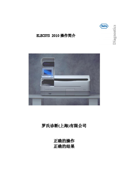
Elecsys 2010操作简介
E L E C S Y S2010操作简介罗氏诊断(上海)有限公司正确的操作正确的结果功能键说明:1.按此键启动测试2.按此键加样停止,但已加样的继续分析3.按此键停止仪器工作4. 按此键进入急诊模式,处理急诊样本5. 按此键显示刚发生的警报信息,并可关闭报警声音6. 滚屏键.7 . 删除键8. 取消键.9. 确认键10.打印或手工发送报告菜单键说明:1.按此键查看试剂,消耗品装载情况及蒸馏水及废液水平2.按此键进入样本,定标,质控编辑界面3. 按此键查看标本结果,定标结果,质控结果4. 按此键进入质控统计情况5. 按此键查看当前仪器工作情况(样本,定标,质控处理情况).6. 按此键进入功能界面.操作菜单:1. 开机1.1注意: 在开机前,必须检查数据备份盘是否存在,是否打开打印机开关。
1.2检查数据备份盘:打开操做台前的门,检查数据备份盘是否在软驱内。
1.3打开打印机如果打印机未开启,打开位于打印机前右侧的开关。
当打印机打开时,绿灯亮。
同时检查打印纸是否足够。
注意:打印机型号可根据国家而不同1.4打开分析仪分析仪的开关通过位于操做台前的开关来控制。
按开关的右端使之处于ON的位置,开关上的绿灯亮表明电源已打开。
1.5登录开机短时间后,仪器启动完成.触摸屏幕显示状态的是分析仪关闭时的最后状态。
根据下列步骤操作:按STATUS进入STATUS屏幕,如下所示:不管系统是否被使用,OPERATOR ID总在屏幕上的相同位置❑按OPERATOR ID,输入你的号码(1-99)。
❑按ENTER确认。
2.开始样本检测前的注意事项2.1目测检查❑各针是否良好,是否有粘附物。
❑管道是否被夹和被折。
❑吸液针管路是否有气泡,如有,检查接头部分并作冲洗。
❑样品/试剂加载区和孵育器表面保持干净,吸样区和孵育器上的液体可能引起加样头(TIP)或反应杯被黏着,是造成抓手机械故障的隐患。
样品/试剂加载区和孵育器2.2检查各耗材库存情况按INVENTORY显示库存屏幕。
diasys仪器说明书
前言美国DiaSys“戴西斯”公司在分析体液方法学、细胞计数技术应用上广泛地进行研究,并以其高质、全球专利产品尿沉渣定量分析工作站而著称全世界,对标准化作出贡献。
R/S 2003尿沉渣定量分析工作站包含的流动计数室装置是由一块高清晰度的光学玻璃与合金铝板组成。
在工作中,流动计数板置于显微镜载物台上,计数室提供一个恒定的容积和厚度,每份标本量是恒定的。
因此,无论何时何地都有能充分满足实验室内和实验室间尿沉渣分析的标准化要求。
戴西斯工作站已荣获NCCLS(美国临床检验标准化委员会)和CLIA(临床实验室改进法案)的推荐,并获得FDA(美国食品医药管理局)和UL(保险者实验室)的认可,被全世界各国实验室广泛使用。
NCCLS 和CCCLS(中国临床检验标准分委会)要求在所有实验室对尿沉渣检查按国际标准进行准确分析,并要以每单位体积(XX细胞/ul、XX管型/ul)报告,放弃不准确、不标准的半定量方法。
R/S2003工作站的推广使用得到了CCCLS的充分支持,它从根本上解决了目前国内尿沉渣分析中存在的标准化问题。
经卫生部临检中心、浙江省临检中心、中国医科大学附一院、中山医学院附院、第二军医大学(长征医院)、广州医学院(附属二院)、湖南省人民医院、宁夏医学院(附属一院)、广州市第一人民医院等用户的使用中获得一致好评。
戴西斯尿沉渣工作站以其准确度高、精密度好、操作简便、快捷、使用安全、节省成本等特点,成为临床实验室必备的尿沉渣分析标准化产品。
尿沉渣系统工作站使用说明一、概述尿液分析是目前临床实验室常规的检测项目之一,目前常用的方法是采用尿液分析仪对尿样进行干化学分析法。
虽然尿液干化学分析已取得了很大进展,并为临床实验室提供了筛选手段,但干化学分析不能替代对尿液有形成分的显微镜检查。
尿沉渣分析是用显微镜或仪器对尿液有形成分进行检查,识别尿液中细胞、管型、结晶、细菌、寄生虫等各种病理成份,对泌尿系统疾病作出诊断、定位,鉴别诊断及预后判断。
DiaSysFE-2粪便分析工作站介绍
·DiaSys FE-2粪便分析工作站专栏·DiaSys FE-2粪便分析工作站介绍许建邦[关键词] 粪便显微镜检查;寄生虫病粪便检验对消化系统疾病及寄生虫病的诊断和治疗有重要临床价值,显微镜检查更是必不可少检查项目之一。
下面,介绍一种按标准化要求研制的完整的粪便标本收集、操作、镜检的分析系统——DiaSys FE-2自动粪便显微镜分析工作站(简称DiaSys FE-2工作站)。
DiaSys FE-2工作站是美国DiaSys Corporation 根据NCCLS(美国临床检验标准委员会)和CLIA(临床实验室改进法案)导则的要求研制并经TÜV Pheinland(德国莱菌TÜV)确认在世界各国实验室广泛应用的产品。
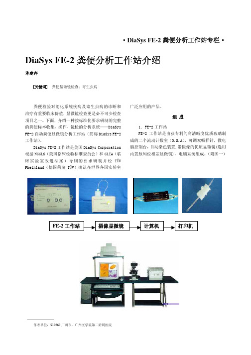
组 成1.FE-2工作站FE-2工作站是由获专利的高清晰度优质玻璃制成的二个流动计数室(O.S.A),可调双吸样针,微电脑控制台,自动染色装置,带摄像的优质显微镜(选用内置数码位相差显微镜),电脑系统组成。
(附图一)作者单位:510260广州市,广州医学院第二附属医院2.Parasep®粪便离心管Parasep粪便离心管是一种快速、一次性过滤器,利用三次过滤套环技术提供洁净收集标本和高效率浓缩寄生虫卵、幼虫、原生动物包囊、球虫卵囊等。
(附图二)3.兼容性的离心机配用适合标准离心机斗。
混合室(高清晰度的聚丙烯)标本室过滤元件专利过滤环高密度聚丙烯两层矩形过滤层隔离大颗粒分子,不堵塞425um的气孔(相当700mm2铜筛)残渣收集所隔离的颗粒物收集起来,防止离心过程出现堵塞现象。
气/液封和安全锁防止生物危害物质释放;安全锁保证安全处理。
完整流器匙形锥形沉渣可检测寄生虫卵、蚴、原生动物包囊、球虫卵囊特 点一、操作简易按指示灯提示按钮,工作站将自动完成吸样、重悬浮、染色(自选)、定量标本输送、自动冲洗全部过程。
二、定量检测每次定量吸入粪便浓缩物15ul。
安道斯PH计说明书

2.1
仪器外形尺寸图
产品说明
PH/0RP108 型微电脑工业控制仪表是用于测试溶液 pH/ORP 值的精密 仪表,其功能全,性能稳定,操作简便等特点,使其成为工业企业测试和控 制 pH/ORP 领域的理想仪表。 PH/0RP108 型仪表采用带背景光 LCD 显示。
恢复出厂设置 具备错误指示 具有非缓冲液校准 自动/手动温度补偿 光电隔离式电流输出 自动识别标准液 循环式桉键调节程序 2.2 桉键操作声光回馈 仪器安装及开孔尺寸图 如果需在同一面板上安装多个仪表,仪表间须保留最小间隙,如下图所示。 PH/0RP108 型仪表可配各种类型 pH 电极。
树脂高分子物 质
8、
稀酒精、丙酮、 乙醚
电极正常使用时间为一年左右,老化后应及时更换新的电极。
15 ○
2 ○
22
此控制过程是: 当石灰水溶液的 pH 值大于 9.00 时, 高点继电动打器自 七、保养 开,向中和池加注盐酸溶液。随着添加的进行,中和池液体的 pH 值将慢慢 下降,当下降到 6.00 时(高点 7.50-迟滞量 1.50=6.00) ,高点继电器自动关 本控制器在一般正常操作情况下,无须做任何保养,唯电极须定期清 闭。此后,中和池的液体将始终保持在 6.00 与 9.00 之间。该过程中若想减 洗和标定,以确保获得精确稳定的测量值和系统的正常稳定运行。 小范围,无需更改高点,只需将迟滞量减小即可。将迟滞量设置为 0.20,中 和后的废水的 pH 值保持在 7.30-7.70 之间。若将高点设置为 7.00,迟滞量设 PH/ORP 电极使用及维护 置为 0.50,则中和后的废水的 pH 值保持在 6.50-7.50 之间。 1、 电极在测量前必须用已知 PH/ORP 值的标准缓冲液进行标定, 为提 10.3 脱硫控制 如某一工厂的锅炉排出含有二氧化硫的废气, 采取的治理方式是使用碱 高测量精度,缓冲液的 PH/ORP 值要可靠,且愈接近被测值愈好。 性溶液(如氢氧化钠)吸收。为达到理想的吸收效果,需将如氢氧化钠液体 2、 电极前端的敏感玻璃球泡不能与硬物接触,任何破损和擦毛都会使 的 pH 值保持在一定范围内。假设工艺上要求要保持在 10.00 与 11.00pH 之 间,此时,可用高点继电器控制。将高点设置在 10.50pH(H=10.50),迟滞 电极失效。 量设置为 0.50pH(d=0.50) 。 3、 电极接线端子必须保持高度清洁和干燥,如有玷污可用医用棉花和 此控制过程是:当氢氧化钠溶液遇二氧化硫时将发生中和反应,pH 呈 下降趋势。当下降至 10.00 时(高点 10.50-迟滞量 0.50=10.00) ,高点继电器 无水酒精揩净并吹干,防止电极引线二端短路,否则将导致测量失效或 自动打开, 补充添加氢氧化钠。 随着添加的进行, 吸收液体的值将慢慢上升, 失败。 当上升到 11.00 时(高点 10.50+迟滞量 0.50=11.00) ,高点继电器自动关闭。 此后,用于吸收二氧化硫的液体将始终保持在 10.00 与 11.00 之间。 4、 测量前,应注意将玻璃泡内的气泡甩去,否则将造成测量误差。测 10.4 电极线加长方法 量时,应将电极在测量溶液中搅动后静止放置,以加速回应。 第一步:剥线 用刀把外面层的皮给剥掉后就会露出网线和一根导线(工具自选)如果 5、 测量前和测量后,都应用去离子水清洗电极,以保证测量精度。在 是温补电极里面有三根线除了一根是电极线还有两根都是温补线,透明的是 粘稠试样中测定后,电极需用热去离子水反复冲洗多次,以除去粘在玻 电极线;然后把三根线剥出合适的长度;把两边的接头都剥好。 第二步:接线 璃膜上的试样,或先用适宜的溶剂清洗,再用蒸馏水洗去溶剂。 如果现场有烙铁的话那就把两个接头相应的线焊上;如果没有就把相应 的线拧紧在一起;记住一定要拧紧!避免 在工作过程中托落。然后用生胶带 绑好绑平;然后用缩套管套上,用电热吹风机供下让其缩紧。如果现场没有 电热吹风机的话那就用打火机也可以均匀的烤下让其缩紧。
检验科SOP文件

第一篇 绪 论第一节检验项目一.临检室开展的检验项目:检验项目 检验仪器 试剂名称 检验方法血常规 TEK200 配套试剂 电阻抗法、光电比色ABO血型鉴定 ——一氧化碳血红蛋白——定性检查尿液干化学 Uritest-300 —— 光电比色尿沉渣 DiaSys R/S 2003 —— 标准计数池镜检 尿妊娠试验 ——便常规一般性状检查,显微镜检查:细胞类型、食物残渣、寄生虫卵或原虫化验检查,隐血试验。
脑脊液检验一般性状检查:颜色、透明度、凝固性;显微镜检查:细胞总数、白细胞数及分类浆膜积液检验一般性状检查:颜色、透明度、凝固性;显微镜检查:细胞总数及有核细胞计数、有核细胞分类。
精液检验一般性状检查:量、颜色及透明度、粘稠和液化、酸碱度;显微镜检查:活率、活动力、数量、形态、其它细胞。
前列腺液检验:红细胞、白细胞、卵磷脂小体、其它细胞阴道分泌物检验:清洁度、滴虫、霉菌。
二.血液室开展的检验项目:编写者:审批者:审批日期:Page 1 of 213检验项目 检验仪器 试剂名称 检验方法 血象检验骨髓象检验红斑狼疮细胞检验血凝项检验 血凝分析仪CA530 配套试剂 详见仪器操作 血流变检验 LBY-N6B血流变仪 —— 同上三.生化室开展的检验项目:检验项目 检验仪器 试剂名称 检验方法肝功(ALT AST ST/LT GGT ALP TP ALB GLO A/G TBIL DBIL IBIL )、肾功(BUN CRE UN/CR UA CO2CP)、心肌酶(CK CKMB α-HBDH LDH LD/HB)、血脂(CHO TG HDL LDL)、离子(K Na Cl Ca Mg P)、淀粉酶(AMY)、血糖(GLU)、风湿系列(CRF ASO CF)、尿微量蛋白 自动生化分析仪OLYMPUS AU400四.免疫室开展的检验项目:检验项目 检验仪器 试剂名称 检验方法肺支原体检验 —— 金标免疫斑点法 人类免疫缺陷病毒HIV 1+2型抗体诊断—— 金标法梅毒检验 —— 梅毒甲苯胺红不加热血清试验诊断试剂盒心肌抗体检验 抗心肌(AHMA)IgG抗体酶联试剂盒结核抗体检测 —— 金标免疫斑点法 人囊虫病检测 —— 人囊虫病(CYT)检测试剂盒甲型肝炎病毒IgM 抗体诊断 洗板机、酶标仪 甲型肝炎病毒IgM抗体诊断试剂盒酶联免疫法丙型肝炎病毒抗体(Anti-HCV)诊断 洗板机、酶标仪 丙型肝炎病毒抗体诊断试剂盒酶联免疫法编写者:审批者:审批日期:Page 2 of 213戊型肝炎病毒抗体诊断洗板机、酶标仪 戊型肝炎病毒抗体诊断试剂盒酶联免疫法乙型肝炎病毒表面抗原诊断洗板机、酶标仪 乙型肝炎病毒表面抗原诊断试剂盒乙型肝炎病毒表面抗体诊断洗板机、酶标仪 乙型肝炎病毒表面抗体诊断试剂盒乙型肝炎病毒核心抗体诊断洗板机、酶标仪 乙型肝炎病毒核心抗体诊断试剂盒乙型肝炎病毒e抗原诊断洗板机、酶标仪 乙型肝炎病毒e抗原诊断试剂盒乙型肝炎病毒e抗体诊断洗板机、酶标仪 乙型肝炎病毒e抗体诊断试剂盒FT3 ACS:180PLUS 配套试剂FT4 ACS:180PLUS 配套试剂TSH ACS:180PLUS 配套试剂AFP ACS:180PLUS 配套试剂CEA ACS:180PLUS 配套试剂ISI ACS:180PLUS 配套试剂CpS ACS:180PLUS 配套试剂五.微生物室开展的检验项目:检验项目 检验仪器 试剂名称 检验方法 细菌培养+药敏试验 计算机 生化管及药敏纸片 对应生化、测直径 淋球菌涂片检验 显微镜、玻片 革兰染液 涂片镜检 滴虫、霉菌涂片检验 显微镜、玻片 革兰染液 涂片镜检 结核杆菌涂片检验 显微镜、玻片 抗酸染液 涂片镜检 院内感染监测 根据标准分析注:以上表单内容若有疏漏之处,详见第三篇检验仪器操作部分。
亚斯兰特仪表说明书
亚斯兰特仪表说明书一、本产品可用于电力稽查、物业管理、工厂用电、电力生产维护等各行业中与用电计量相关的场所,使用过程具有一定的危险性,必须由具有电工职业资格以上的人员、或经过专门培训的技术人员使用。
二、本产品具有LCD显示屏,使用时严禁对LCD碰撞、任何液体的淋湿、尖硬物体的划压,严禁任何可能对LCD造成损伤的操作及行为。
三、本产品带有可充电聚合物锂电池,必须使用专用的充电器,充电时必须有人看护。
四、本产品为精密电子仪器,严禁拆卸。
电能质量分析仪,是对电网运行质量进行监测及分析的专用便携式产品。
可以提供电力运行中的谐波分析及功率品质分析,能够对电网运行进行长时间的数据采集监测。
同时配备电能质量数据分析软件,对上传至计算机的测量数据进行各种分析。
使用仪表前,了解相关注意事项。
五、特点:一种电能质量分析专用仪表。
使用ARM和DSP以及16M字节的存储器;可进行测量,并保存数据,将其上传到PC机进行分析;模块化结构,设计合理,运行可靠。
中文菜单操作,简单易学。
可使用USB盘更新仪表软件,软件升级简单、方便;在PC机上用电能质量数据分析软件对测量数据进行详细分析。
1、技术指标-仪表基本功能-仪表检测功能一览表-序号项目描1电压/电流/频率可测量三相电压、零线电压、三相电流、零线电流、频率等。
2、谐波测量可测量至50次谐波,测量结果包括各次谐波电压、谐波电流的幅值、电压谐波的总失真度(总畸变率)、各次电压谐波/电流谐波含有率。
3、功率/电能测量可测量三相视在功率、有功功率、无功功率、功率因数、三相电能等。
4、三相不平衡测量可测量三相电压不平衡度及正序、负序、零序电压;三电流不平衡度及正序、负序、零序电流;可显示电压矢量、电流矢量。
5、监测记录可长时间地记录基本的(稳态)电能质量参数,记录时间间隔从3秒到30分钟可调。
6.数字示波器可用于查看电压-电流信号波形。
山西亚森血凝用户手册

感谢您购买本公司生产的仪器!使用本公司生产的仪器之前,请您仔细阅读使用手册。
重要说明:本仪器仅限于室内使用。
仪器的电源引线保护接地端与外壳及应用部分连接,必须通过电源插座可靠接地。
在可能有潮湿的地方使用时应加装漏电保护器。
本仪器无高压端子、无冷却装置、对操作者无生理效应、无有限的机械稳定性,因此,不在本仪器外部做网电源功率输出、生理效应、高压端子装置、冷却条件、机械稳定性、接地端子、可拆卸的保护装置等标记,特此声明。
本公司生产的仪器内均装有电源稳压器,一般无需外接稳压器。
仅当外界电源电压波动超过±10%时,可使用UPS类稳压器,不可使用普通稳压器。
操作仪器时,应注意保持操作面清洁,不可使杂物及液体进入仪器内部,以免导致仪器损坏。
请用中性清洗液清洁仪器表面的污物,勿使用任何溶剂类液体(如酒精等)。
保持良好的工作环境、避免不经意的错误操作,是仪器保持优良性能及延长使用寿命的重要环节。
请勿打开机箱盖,机内没有用户可调整部件。
请保存仪器的原包装,以备维修时发寄使用。
本说明书中,凡有“★”处,请特别注意。
半自动血液凝固分析仪有FB-20、FB-40两种型号。
此处附一份仪器装箱单,如装机时有不符之处,请与供应商联系。
装箱单FB-20型血液凝固分析仪说明一概述FB-20型血凝仪是测试人体部分凝血因子活性的专用仪器。
仪器对试剂开放,适用于采用凝固法测试凝血因子的各种凝血试剂。
仪器设有两个测试位、六个预温位和五个试剂预温位(含一个搅拌位),可同时对两份标本进行凝血测试。
仪器安装有大屏幕液晶显示器,用于操作提示、结果显示和菜单设置;有低噪音高速热敏打印机,可快速输出测试结果;有存储功能,可存储最近99次测试结果;有RS232串行接口,可与计算机联网交换数据和信息。
仪器采用光电-钢珠法测试凝血过程,该方法不受原血浆粘度和溶血、脂血、黄疸等样品干扰,并采用电子联动移液器,减少人为误差,可以保证测试有良好的精确度和重复性。
Shimadzu ASI-100和ASI-100T自动样品注射器产品说明书
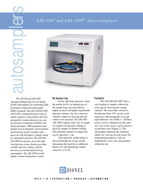
The ASI-100 and ASI-100TAutomated Sample Injectors are highly flexible autosamplers for automating high performance liquid chromatography(HPLC) methods. The ASI-100/ASI-100T,which allows independent processing of sample sequences and methods, has been designed for routine laboratory use and incorporates exceptional reliability and high performance. With integrated safety features such as automatic vial recognition and electronic needle resistance shut-down, the ASI-100 family is ideally suited for unattended operation. The ASI-100/ASI-100T incorporates an in-line split-loop injection system, thereby providing variable injection volumes with the precision of conventional fixed-loop autosamplers. The ASI-100T provides sample carousel temperature control.No Sample LossIn-line split-loop injection, where the needle itself is an integral part of the sample loop, not only delivershighly accurate and highly reproducible injection volumes, but also conserves valuable sample by drawing only the volume to be injected. The ASI-100/ASI-100T requires only 5 µL of sample to complete an injection, making it ideal for samples of limited volume.The minimum amount of sample that can be injected is 1 µL.After injection, mobile phase is directed through the in-line needle,eliminating the need for an additional flush cycle and minimizing sample carryover (< 0.1%).FlexibilityThe ASI-100/ASI-100T allows easy loading of samples without the extra step of removing the sample carousel. The removable carousel is divided into three 120˚ sectors; each segment is interchangeable to accept eight different vials (Table 1). All three sectors can be configured for the same size vials or the sectors can be mixed to accept three sizes (Figure 2). The autosampler automatically identifies which size vials are in each sector. For programming purposes, vials areidentified by sector, row, and position within the row.a u t o s a mCapacityThe number of samples that can be analyzed using the ASI-100/ASI-100T depends on the type of segments in the carousel. Three 4-mL vial segments hold 63 samples, three 2-mL segments hold 117 samples, and three 1.2-mL segments hold 192 vials. Each of these configurations also permits the use of three additional 4-mL wash vials. (See Table 1.)AutomationThe ASI-100/ASI-100T can be programmed in two ways: directly from its front panel using easy-to-follow menus, or externally throughC HROMELEON™ chromatography management software (Figure 2), which provides significantly enhanced capabilities. These enhancements include random sample access, variable injection volume for each sample, a variable number of replicates, definition of longer sample batches, definition of more sample methods, and automatic documentation of measuring conditions via the Audit Trail feature. In addition, a second electrically activated switching valve for column switching can be controlled.When necessary, the autosampler can be interrupted during a sequence to run a priority sample immediately. By pressing the “Quick Sample” button on the front panel and programming the position of the sample to be run, the sampler will finish processing the current sample, then run the specified sample and return to the previously programmed sequence.ASI-100P for Semi-preparative Usage For semi-preparative applica-tions, the ASI-100P was designed for low backpressure contribution even at high flow rates. The carousel of theAS1-100P is equipped with semi-preparative 4-mL vial segments and a 2500 µL syringe and sample loop. The ASI-100PT provides sample tempera-ture control.Figure 2. The ASI-100/ASI-100T can be programmed with C HROMELEON chromatography management software.Sample PreparationThe ASI-100/ASI-100T can be programmed through the front panel or through C HROMELEON to perform several operations prior to sample injection that normally would be performed by the analyst before placing the sample in a vial. These operations include proce-dures such as reagent addition, sample dilution, standard additions, and stan-dards preparation. Mixing is accom-plished through a draw and dispense pro-cess; with C HROMELEON, multiple draw and dispense operations can be per-formed. The autosampler also can be programmed to perform a “Wash” proto-col when required.Sample Temperature ControlThe ASI-100T provides samplecarousel temperature control using Peltier heating and cooling. The temperature range of the ASI-100T is 4–45 o C (39–113 o F), with maximum cooling of -18 o C from ambient. Maximum heating is +35 o C from ambient.ServiceabilityThe ASI-100/ASI-100T is easy to operate and maintain. Syringe and sample loop changes are made through an access panel on the right front corner (Figure 3). The standard syringe and sample loop volume is 250 µL; other volume options are 100, 1000, and 2500 µL. It is recommended that the syringe volume and sample loop Figure 3. Easy access is provided to the syringe and sample loop.size are equivalent.To aid in maintenance schedules,the autosampler keeps an internal log ofactions that have been performed. Byaccessing the “Counters” submenu,users can view statistical informationfor individual counters. The counterstrack the following parameters:•Number of executed injections•Number of injection valve statorand rotor movements•Wear of the needle port•Wear of the needle seal•Wear of the syringeASI-100P for Semi-preparative UsageFor semi-preparative applica-tions, the ASI-100 was designed forlow backpressure contribution even athigh flow rates. The carousel of theASI-100P is equipped with semi-preparative 4-mL vial segments and a2500 µL syringe and sample loop. TheASI-100PT provides sample tempera-ture control.Printed on recycled and recyclable paper.ASI-100, ASI-100T, and C HROMELEON are trademarks of Dionex Corporation.Vespel is a registered trademark of E.I. duPont de Nemours & Co.Dionex Corporation Dionex CorporationDionex U.S. Regional Offices Dionex International Subsidiaries1228 Titan Way Salt Lake City Technical Center Sunnyvale, CA (408) 737-8522Austria (01) 616 51 25 Belgium (015) 203800 Canada Germany 06126-991-0P.O. Box 36031515 West 2200 South, Suite A Westmont, IL (630) 789-3660Italy (06) 66 51 50 52 Japan (06) 6885-1213 The Netherlands (062) 205 99 66 Sunnyvale, CA Salt Lake City, UT Houston, TX (281) 847-565294088-360384119-1484Atlanta, GA (770) 432-8100(408) 737-0700(801) 972-9292Marlton, NJ (856) 596-0600©2002 Dionex Corporation。
LDP1SA1B型号单循环检测器商品说明说明书

Mounting Relay Ordering no.Ordering no.Ordering no.Supply: 24 VAC/DC Supply: 115 VAC Supply: 230 VAC Single loopSPDTLDP1SA1BM24 3209LDP1SA1B1153209LDP1SA1B2303209Inductive SensorsSingle Loop DetectorsType LD with teach-in spec. 3209• Single loop detector• Automatically adjustment of detection level• Manual sensitivity for compensations of variations • Easy installation via 11 pin circular plug•Rated operational voltage:24 VAC/DC, 115 VAC or 230 VAC• Pulse or presence relay output • Output 1A/250 VAC SPDT relay• LED indication for power, relay status and loop fault • Sensitivity boost• Selectable frequency – prevents cross-talkProduct DescriptionThe principle is based on a change in the inductance within the loop when a metal-lic object (vehicles) is passing.The microprocessor evaluates the changes.Loop detectors for detection of vehicles. The vehicle loop detector is designed to handle all parking, drive-through and access control applications for controlling doors, gates, barri-ers or fences.Type SelectionSpecificationsLDP1 - 3209Mode of OperationDescription Single Channel Detector CommentsSense adjust Dip-switch 1,2,38 levelsRelay pulse output length Dip-switch 40.2 or 1 secondRelay pulse output mode Dip-switch 5Entering or leaving vehicle Relay output filter (on-delay)Dip-switch 6 2 secondsSense boost Dip-switch 7Change Frequency Dip-switch 8“Cross talk”Pulse relays/presence relays 2 functions1 Sense Level Select - MSB2 Sense Level Select3 Sense Level Select - LSB4 Pulse length 1 sec.4 Pulse length 0.2 sec.5 Pulse mode leaving 5 Pulse mode entering6 On delay off 6 On delay 2 sec.7 Sence boost Off 7 Sence boost On8 Change Frq. Off 8 Change Frq. OnDIP switchesDip Switch SettingsSensitivity adjustmentLDP1SenseDIP1DIP2DIP3Change in LLevel (%)0OFF OFF OFF 0.011OFF OFF ON 0.022OFF ON OFF 0.053OFF ON ON 0.14ON OFF OFF 0.25ON OFF ON 0.56ON ON OFF 1.07ONONON2.0Loop DiagramWhen sealing up the groove,ensure that the temperature of the sealing compound does not exceed the max tempera-ture of the loop insulation, as this might cause an earth fault.Loop turnsThe number of turns strongly depends on the circumference of the loop. The smaller the loop, the more turns are required.Cable Recommandations- Use 1.5mm squared e silicon coated cable, if placed directly into the ground - Use 2m of spacing between two adjacent loops.- Use screened feeder cable in electrically noisy environments or where feeder runs parallelLoop installationThe loop geometry must be adapted to the respective application. The setup will be optimal if the loop has thesame size as the object to be detected.After determing the loop geometry, a groove must be cut in the ground for installing the loop.Cut an inclined groove of 45°angle at the corners of the loop, which will protect it from excessive wear.Clean the groove for moisture and place the wire as tight as possible along the button of the groove.Before sealing up the groove,it is recommandable to check the loop inductance using a measuring device. Optimum value: 80-300 µH.to power cables.Loop circumferenceNo. of turns(m)>1026-103<64LDP1 - 3209Important:Reset the detector after changing the Dip-switch settingsDimension DrawingAccessoriesDelivery Contents• 11 pole corcular socket ZPD11• Detector• Packaging: Carton boxPlug version45216335,580Pin configurationLDP1 - 3209Wiring DiagramPresLoopPin n.Single Channel Detector 1Supply 2Supply3Pulse relay NO 4Earth5Presence relay COM 6Presence relay NO 7Loop 8Loop9Pulse relay COM 10Presence relay NC 11Pulse relay NC。
diascreen 使用手册

标题:深度了解diascreen:一份全面的使用手册在当今数字化时代,人们对于数据的收集、分析和应用变得越来越重要。
在医疗行业中,随着医学技术的不断进步,诊断和治疗也变得更加精准和个性化。
而diascreen作为一款先进的医疗设备,为医生和患者提供了便捷、准确的血糖监测服务,成为了糖尿病患者的得力助手。
1. diascreen的功能和特点diascreen是一款便携式的血糖监测仪,其特点在于高度的准确性和便捷性。
通过diascreen,患者可以随时随地进行血糖监测,有效地管理自己的健康状况。
除了基本的血糖监测功能,diascreen还具有数据存储、数据共享和远程监测等特点,方便医生对患者的情况进行及时跟踪和分析。
2. 如何正确使用diascreen在使用diascreen之前,首先需要进行正确的操作步骤。
患者需要准备好测试所需的试纸和携带式血糖仪,然后进行手部卫生。
随后,将试纸插入血糖仪中,进行采血和血糖测试,最后将结果记录在血糖监测表格中,方便随时回顾。
3. diascreen的数据管理和共享除了单次的血糖测试外,diascreen还可以帮助患者管理和共享自己的血糖数据。
通过连接手机App,患者可以将自己的测试数据实时上传至云端,方便医生随时查看。
患者自己也可以通过手机App查看自己的血糖趋势和变化,更好地了解自己的身体状态。
4. 个人观点和总结作为一位医学工作者,我个人对于diascreen的使用深有体会。
它不仅在我工作中带来了便捷,更重要的是,它为患者提供了全新的医疗体验。
尤其对于糖尿病患者来说,diascreen的使用可以让他们更加了解自己的身体状况,更好地管理自己的健康。
我强烈推荐医生和患者使用diascreen,它将成为医疗行业数字化的重要一步。
通过上述内容,我们对diascreen的功能、正确使用方法、数据管理和个人观点进行了全面的探讨。
希望这篇文章能够为大家提供对diascreen的深入了解,让医生和患者都能从中受益。
Diagnostix 手表型血压仪用户指南说明书

Assembled, inspected, andpackaged in the U.S.A.tel: 631-273-9600 toll free: 1-800-232-2670fax: 631-273-9659*****************(6/3/2021)Printed in the U.S.A.Instructions for UseDiagnostix TM AneroidsPocket, Palm, Clock Type Inflate the cuffClose the Adflow valve by turning thumbscrew clockwise.Palpate the radial artery while inflating the cuff. Be sure to inflate cuff quickly by squeezing bulb rapidly.Inflate cuff 20-30 mmHg above the point at which the radial pulse disappears. NOTE: Cuff pressure range is 0 mmHg to 300 mmHg.Position the StethoscopePosition the chestpiece in the antecubital space below the cuff, distal to the brachium. Do not place chestpiece underneath the cuff, as this impedes accurate measurement. Use the bell side of a combination stethoscope for clearest detection of the low-pitched Korotkoff (pulse) sounds.Deflate the cuffOpen the valve to deflate the cuff gradually at a rate of 2-3 mmHg per second.MeasurementRecord the onset of Korotkoff sounds as the systolic pressure, and the disappearance of these sounds as diastolic pressure. (Some healthcare professionals recommend recording diastolic 1 and diastolic 2. Diastolic 1 occurs at phase 4).NOTE: It is recommended that K4 be used in children aged 3 to 12, and K5 should be used for pregnant female patients unless sounds are audible with the cuff deflated, in which case K4 should be used. K5 should be used for all other adult patients.After measurement is completed, open valve fully to release any remaining air in the cuff. Remove cuff.Care and MaintenancePocket Gauge: After measurement, fully exhaust cuff then wrap cuff around gauge and bulb and store in zippered carrying case.Palm Gauge: After measurement, fully exhaust cuff and store in zippered carrying case. If unit will not be used for an extended period of time, leave the trigger valve in the full exhaust position.Clock Gauge: After measurement, fully exhaust cuff then wrap cuff around bulb and store in storage compartment.NOTE: This product will maintain the safety and performance characteristics specified at temperatures ranging from 50°F to 104°F (10°C to 40°C) at a relative humidity level of 15% to 85%. This device can safely be stored at temperatures ranging from -4°F to 158°F (-20°C to 70°C) with a relative humidity of 15% to 85%.Manometer: Your Diagnostix brand pocket aneroid gauge (#800 or #802), palm aneroid (#804N) or clock aneroid (#805) requires minimal care and maintenance.The manometer may be cleaned with a soft cloth but should not be dismantled under any circumstances.Should the indicator needle of the manometer rest outside the oval calibration mark (Figure 5), then the manometer must be re-calibrated to within ±3 mmHg when comparedto a reference device that has been certified to national orinternational measurement standards. A manometerwhose indicator needle is resting outside of this mark isNOT acceptable for use.In the event that the gauge is ever in need of calibration, simply return to ADC. Damaged or broken parts will be replaced as needed at a minimum charge. Refer to the warranty for specific details of warranty coverage.The manufacturer recommends a calibration check every 2 years.Cuff Cleaning and DisinfectingUse one or more of the following methods and allow to air dry: • Wipe with mild detergent and water solution (1:9 solution). Rinse. • Wipe with Enzol per manufacturer’s instructions. Rinse. • Wipe with .5% bleach and water solution. Rinse • Wipe with 70% isopropyl alcohol.• Launder with mild detergent in warm water, normal wash cycle. Remove bladder first. Cuff is compatible with 5 wash cycles.Low-Level DisinfectionPrepare Enzol enzymatic detergent according to the manufacturer’s instructions. Spray detergent solution liberally onto cuff and use a sterile brush to agitate the detergent solution over entire cuff surface for five minutes. Rinse continuously with distilled water for five minutes. To disinfect, first follow the cleaning steps above, then spray cuff with 10% bleach solution until saturated, agitate with a sterile brush over entire cuff surface for five minutes. Rinse continuously with distilled water for five minutes. Wipe off excess water with sterile cloth and allow cuff to air dry. Do not iron cuff. Do not heat or steam sterilize cuff.Manometer Quality ControlA serial number and lot number are automatically assigned to every aneroid during manufacturing, ensuring every item is controlled.The serial number can be located on the faceplate of each aneroid (Figure 6).The lot number is located on the outside label of the manometer packaging (Figure 7).StandardsANSI/AAMI/ISO 81060-1:2007, EN/ISO 81060-1:2012DisposalWhen your sphygmomanometer or any of its parts have reached their end of life,please be sure to dispose of them in accordance with all regional and national environmental regulations. Devices that have become contaminated should be disposed of in accordance with all local ordinances and regulations.(Figure 6)Serial NumberWarrantyADC ® warrants its products against defects in materials and workmanship undernormal use and service as follows:• Warranty service extends to the original retail purchaser only and commences with the date of delivery.• Your Diagnostix™ manometer is warranted for life. The manometer is warranted to remain accurate to ±3mmHg (or the prevailing standard) over its full range when compared to a reference standard for life.• Inflation system components (cuff, bladder, tubing, bulb, valves, and connectors) are warranted for three years.What Is Covered: Replacement of parts, and labor.What Is Not Covered: Transportation charges to ADC. Damages caused by abuse, misuse, accident, or negligence. Incidental, special, or consequential damages. Some states do not allow the exclusion or limitation of incidental, special, or consequential damages, so this limitation may not apply to you.To Obtain Warranty Service: Send item(s) postage paid to ADC, Attn: Repair Dept., 55 Commerce Dr., Hauppauge, NY 11788. Please include your name and address, phone no., proof of purchase, and a brief note explaining the problem.Implied Warranty: Any implied warranty shall be limited in duration to the terms of this warranty and in no case beyond the original selling price (except where prohibited by law). This warranty gives you specific legal rights and you may have other rights which vary from state to state.NOTE: Store gauge with valve in full exhaust position.(Figure 5)To register your product visit us at/support/warranty-registration(Figure 7)ADC ®55 Commerce Drive Hauppauge, NY 11788 U.S.A. 30855 Langenhagen GERMANYCuffCoiled Tubing Bulb ValveManometerADC Aneroid Sphygmomanometer(manometer, cuff, bladder, bulb and valve)Thank you for choosing an ADC Diagnostix Aneroid Sphygmomanometer. Your new aneroid is designed to provide unrivaled durability and unparalleled comfort. Every component has been carefully designed to maximize performance. This Instructions for Use guide refers to ADC model series 700, 703, 705, 720, 728, 731, 732, 740, 750, 752, 778, and 788.Device Description and Intended UseADC aneroid sphygmomanometers are used by professional healthcare providers and individuals trained in the auscultatory blood pressure technique to determine systolic and diastolic blood pressure in humans.Contraindications:Aneroid sphygmomanometersare contraindicated for neonate use. Do not use with neonatal cuffs or neonate patients. Review the size chart for proper age and limb range usage (right).Symbol DefinitionsThe following symbols are associated with your ADCDiagnostix AneroidGeneral WarningsA warning statement in this manual identifies a condition or practice which, if not corrected or discontinued immediately, could lead to patient injury, illness, or death.WARNING: Do not allow a blood pressure cuff to remain on patient for more than 10 minutes when inflated above 10 mmHg. This may cause patient distress, disturb blood circulation, and contribute to the injury of peripheral nerves.If luer lock connectors are used in the construction of tubing,there is a possibility that they might be inadvertently connected to intra-vascular fluid systems, allowing air to be pumped into a blood vessel. Immediately consult a physician if this occurs. Safety and effectiveness with neonate cuff sizes 1 through 5 is not established. If this equipment is modified, appropriate inspection and testing must be conducted to ensure its continued safe use. Do not apply cuff to delicate or damaged skin. Check cuff site Only use the cuff when the range markings indicated on the cuff show that the proper cuff size is selected, otherwise erroneous readings may result. Allow space between patient and cuff. Two fingers should fit in this space if the cuff is correctly positioned. Do not apply cuff to limbs used for IV infusion. Patient should remain still during measurement to avoid erroneous readings. When using with an infant or child cuff, extra care must be taken to prevent over-inflation. With smaller cuffs (infant or child) the cuff can inflate to over 300mmHg with just two full compressions of the bulb. To prevent discomfort or injury to the patient and damage to the instrument, bulb should only be partially squeezed, so that each “stroke” inflates the cuff in 40mmHg to 60mmHg increments until inflated to the desired level. To obtain the greatest accuracy from your blood pressure instrument, it is recommended that the instrument be used within a temperature range of 50°F to 104°F (10°C to 40°C), with a relative humidity range of 15%-85% (non-condensing). Extreme altitudes may affect blood pressure readings. Your device has been designed for normal environmental conditions.Operation of Diagnostix Pocket AneroidsThis booklet contains operating and maintenance information for the Diagnostix 700, 720, 728, and 778 Series pocket aneroid sphygmo-manometers. Please read and retain.Your Diagnostix brand pocketaneroid sphygmomanometer consists of an aneroid manometer(gauge), complete inflation system (Adcuff calibrated nylon cuff, latex-free inflation bladder, squeeze bulb,Most models are preassembled and ready for use. In units requiring assembly, the bulb and valve should connect to the tube closest to the Index Line. The gauge con-nects to the remaining tube.Operation of Diagnostix Palm AneroidsThis booklet contains operating and maintenance information for the Diagnostix 703 and 788 Series, the Pediatric and General Practice multicuff kits, and the 731, 732, and System 5 Cuff Index Line Hang Tab Gauge Artery MarkBulb & ValveBladder &Tubing Your Diagnostix palm-style aneroid includes a manometer with integral bulb and trigger airrelease valve (#804N), Adcuff calibrated cuff with Size Guide ™ marking system, bladder, bayonet-style connector (attached to bladder tubing), zippered carrying case, and instruc-tion booklet. ADC’s Multicuff Systems (731, 732, System 5, GPK, and PMK) contain the #804N manometer and a variety of cuffs with single tube bladders, each equipped with a bayonet-style connector, and a compartmentalized case.Connecting Palm Style Model: 804NLegacy Connector: Assemble the supplied luer slip connector into the connector port on top of palm gauge, rubber gasket side down. Make sure connector is fully seated in the connector port. Slide cuff tubing over the barbed end of the connector. Connector will friction fit onto the tubing of most commercially available ONE-tube cuff and bladder systems (Figure 1).New 804N Connector: Insert metal bayonet connector into metal receiver until it clicks (Figure 2).To Release: Slide receiver collar downward toward gauge until connector releases. Do NOT remove metal receiver from gauge. The palm style manometer is designed To avoid damage to the instrument, do not force connector into port.Using the Trigger ValveDeflation: Gently squeeze the bottom of the trigger to deflate the cuff. Altering the pressure affects the deflation rate.Rapid Exhaust: To exhaust remaining air after measurement is completed, squeeze trigger until it clicks and locks in place.Operation of Diagnostix Clock AneroidsThis booklet contains operating and maintenance information for the Diagnostix 750W series (wall mount), 752M series (mobile), and 750D series (desktop) aneroid sphygmomanometers. Please read and retain.Your Diagnostix 750/752 consists of a large “clockface” aneroid with easy-to-read 6” dial, an integral swivel bracket/cuff storage compartment (wall series only), complete inflation system(which includes the Adcuff nylon cuff with SizeGuide marking system, latex-free inflationbladder, bulb, and Adflow valve), 8-foot length coiled tubing,luer connectors, mounting hardware, and operating instructions. The Diagnostix 752M is mounted on a height adjustable, Spider-Leg ™ 5-leg mobile stand. The Diagnostix 750D is mounted on a desktop stand.To assemble the inflation system, connect coiled tubing to air inlet nipple at bottom of gauge. Insert male luer adapter on bladder tubing into female receptacle at free end of coiled tubing. Store folded inflation system in swivel bracket behind gauge on 750W and 750D or in integral basket on 752M.Adcuff Intended UseADC blood pressure cuffs are noninvasive and are intended for use with manual and automated noninvasive blood pressure measurement devices.ADC’s Size Guide marking system assures use of correct cuff size and proper cuff alignment. Printed Index and Range markings and applicable limb range (in cm) allow easy identification of the correct cuff size. An artery mark printed on both sides indicates bladder midpoint for correct cuff positioning. A convenient nylon gauge hang tab permits flexible use with either pocket aneroids or mercury manometers. Hook-and-loop adhesive surface provides a snug, infinitely variable fit and is designed to withstand a minimum of 30,000 open/close cycles.Measurement ProcedurePatient PositionThe patient should sit or lie comfortably. The arm should be fully supported on a flat surface at heart level. (If the arm’s position varies, or is not level with the heart, measurement values obtained will not be consistent with the patient’s true blood pressure.) When seated, the patient should have their back and arm supported, and their legs should not be crossed. Prior to measurement the patient should relax comfortably for five minutes and should refrain from talking or moving duringmeasurement. Observer should view manometer in a direct line to avoid “parallax error.”Apply the cuffAdcuff nylon cuffs are specially designed to promote the precisely accurate determi-nation of blood pressure. Index and rangemarkings ensure use of the correct cuffsize. The artery mark indicates proper cuffpositioning.Place the cuff over the bare upper arm with the artery mark positioned directly over the brachial artery. The bottom edge of the cuff should be positioned approximately one inch (2-3cm) above the antecubital fold. Wrap the end of the cuff not containing the bladder around the arm snugly and smoothly and engage adhesive strips (Figure 3).To verify a correct fit, check that the Index Line falls between the two Range Lines (Figure 4). (Figure 3)Cuff SizeLimb RangeInches CM Infant 7I 3.5 to 5.5 9 to 14 Child 9C 5.1 to 7.6 13 to 19.5 Sm. Adult 10SA 7.4 to 10.6 19 to 27 Adult 11A 9 to 15.7 23 to 40 Lg. Adult 12X 13.3 to 19.6 34 to 50 Thigh 13T 15.7 to 25.9 40 to 66 Bariatric 12BX 17.3 to 25.9 44 to 66Size ChartGauge Hang TabHook & Loop Trigger ValveGauge Connector Port。
DiaSys软件中文手册

DiaSys定量分析系统软件安装、使用手册目录一、安装调试………………………………………………….4~71、硬件基本配置 (4)2、预装软件 (4)3、安装调试步骤……………………………………….…4~7二、数据流程 (8)三、软件操作………………………………………………….9~101、功能菜单……………………………………………….9~10●主窗口 (9)●镜检窗口 (10)2、使用详解 (11)●登录 (11)●更换登录口令 (11)●病人资料 (12)录入 (12)修改 (12)●镜检…………………………………………………12~13进入 (12)结果录入 (12)添加、删除项目 (13)抓图 (13)保存 (13)镜检默认条件设置 (13)●实验数据……………………………………………..13~14浏览 (13)修改、删除、保存 (14)历史结果回顾 (14)●图片处理 (15)编辑 (15)浏览 (15)●打印报告单……………………………………………15~16●报告单查询……………………………………………15~16实验数据 (16)浏览 (16)历史结果回顾 (16)图片浏览 (16)打印报告单 (16)●修改报告单 (17)●基本信息设置 (17)●实验项目设置 (18)实验项目 (18)标本描述 (18)结果录入集 (18)●手工录入干化学结果 (18)●批量默认镜检结果 (18)●录入界面设置 (18)定项 (18)定位 (18)●打印参数设置………………………………………19~20●教学系统 (20)●统计分析…………………………………………...…20~21汇总表统计 (20)工作量统计 (20)收费统计 (20)项目阳性率统计 (20)历史结果对照表 (20)四、数据库维护………………………………………………21~22●登录 (21)●数据库备份 (21)●数据库恢复 (21)五、附录 (23)1、常见故障及处理 (23)2、Bayer尿液分析仪通讯口参数列表 (23)一、 安装调试 1、 硬件基本配置2、 预装软件3、 安装、调试步骤● 操作系统设置① 将“短日期样式” 设为“yyyy-mm-dd ”----开始 → 设置 → 控制面板 → 区域设置 → 日期 → 短日期样式 → 选择“yyyy-mm-dd ”→确定 ② 将“屏幕区域”设为“1024x768” ,“颜色”设为“增强色(16 位)”---- 关闭或缩小所有窗口,在桌面中心点击鼠标右键 → 属性 → 设置 → 用鼠标拖动“屏幕区域”的滑块,使其值为“1024x768” ;在“颜色”栏选择“增强色(16 位)” → 确定 → 确定● 软件安装① 将DiaSys 安装光盘放入光驱,稍等片刻,安装向导将会自动运行,如图1-1所示(若安装向导不能自动运行,请打开“我的电脑” ,用鼠标左键双击光驱图标)。
Bio-Rad DiaSTAT糖化血红蛋白A1c测定仪SOP文件
Bio-Rad DiaSTAT糖化血红蛋白A1c测定仪SOP文件1.目的:Bio-Rad DiaSTAT糖化血红蛋白A1c测定仪可体外测定正常人和糖尿病人的糖化血红蛋白,用于糖尿病的辅助诊断和诊疗监控。
2.原理:DiaSTAT 使用低压离子交换液相色谱法,在梯度洗涤液的作用下,从人全血中分离出各种血红蛋白成分,分离出的血红蛋白经415 nm光谱吸收分析后,结果记录和存储在计算机上。
DiaSTAT软件随后对结果进行分析并打印结果报告。
DIASTAT血红蛋白A1c测定仪可从样品管中自动吸取标本,随后进行稀释和分析,每个样本在10分钟内即可完成测定。
3.仪器使用环境:1.无尘、换气良好的环境。
2.避免阳光直接照射。
3.室内相对湿度20~80%4.电源电压变动在220V±10V之内5.有保护性接地4.安全条款:1.使用对人体有危险或发生感染的样品时,请使用橡胶手套,不要直接接触。
如操作人员直接被污染时,用大量的水冲洗、消毒,必要时应及时看医生。
仪器污染时应随时清洗干净且消毒。
2.仪器上面和周围不要放置或使用易燃、易爆物品,避免引起火灾、爆炸。
3.仪器的操作、保养按规定程序进行。
5.标准操作过程5.1开机程序:1)确认试剂量和打印纸充足,废液桶倒空2)打开仪器后侧左下部的电源开关仪器自检后自动进入主菜单5.2关机程序如系统处于主菜单时,可直接关掉电源开关注: 尽量避免在Running状态突然关机5.3常规样本实验5.3.1 样本准备1)全血样本准备(EDTA抗凝全血)a. 将Diastat Dispenser 打开,预热15分钟以上。
b.注意溶血试剂是否用完。
c.将Dispenser对准溶血试剂瓶(注意防止污染),按住拇指开关,喷射四次,使管路通畅。
无气泡。
d.三灯齐亮状态下,可以吸取样本。
e.将Dispenser加样尖置入混匀好的样本管中,没入血样中一些,按住拇指开关一次,自动吸取20 ul样本。
穿刺液有核细胞计数及分类计数操作步骤
·技术交流·穿刺液有核细胞计数及分类计数操作步骤华鑫技术部1.开启DiaSys微电脑控制台、内置数码位相差显微镜、电脑主机的电源;2.双击鼠标左键,进入DiaSys 707程序;3.在《病人信息》之“实验名称”栏目上根据检验目的选择:脑脊液分析;胸水分析;腹水分析;心色液分析;关节液分析……等项,点击鼠标输入;4.点击鼠标“镜检”栏或“F11”;5.在《镜检条件》栏上输入“起始标本号”和“截止标本号”,按“Enter”键确定;6.按DiaSys微电脑控制台的“标本”(Sample)键,通过“可调加样器”自动吸入已准备好的标本(参照染色或不染色标本制备);7.在屏幕界面上根据标本细胞数量多少选择“染色”/“不染色”栏、“染液滴数”栏、“观察小格数”栏,点击鼠标输入;8.点击“细胞计数”栏,计数设定“观察小格数”内细胞,在“实验结果”栏上用键盘输入细胞数,按Enter键确认,仪器自动计算出××(细胞)×106/L 结果;9.点击“中性分叶核细胞”栏,计数格内中性分叶核细胞数并在“实验结果”栏上用键盘输入,按Enter键确认,仪器自动计算出百分率(%)的结果;10.用同法点击“单个核细胞”栏和“内皮细胞”栏,便可计算出细胞百分率(%)的结果。
11.按DiaSys微电脑控制台的“冲洗”(Normal)键,或伸展冲洗(Extended)键,把流动计数室(OSA)内标本冲洗干净。
12.进行下一个标本检查。
附:1.染色标本制备:穿刺液200ul,滴加染色液1滴(50ul),摇匀,备用。
(若不加染色液则加2%醋酸溶液1滴(50ul)亦可)。
2.血性穿刺液作有核细胞计数和分类时加20%醋酸溶液1滴(50ul),摇匀,备用。
3.不染色标本制备:把穿刺液充分摇匀,备用。
- 1、下载文档前请自行甄别文档内容的完整性,平台不提供额外的编辑、内容补充、找答案等附加服务。
- 2、"仅部分预览"的文档,不可在线预览部分如存在完整性等问题,可反馈申请退款(可完整预览的文档不适用该条件!)。
- 3、如文档侵犯您的权益,请联系客服反馈,我们会尽快为您处理(人工客服工作时间:9:00-18:30)。
前言美国DiaSys“戴西斯”公司在分析体液方法学、细胞计数技术应用上广泛地进行研究,并以其高质、全球专利产品尿沉渣定量分析工作站而著称全世界,对标准化作出贡献。
R/S 2003尿沉渣定量分析工作站包含的流动计数室装置是由一块高清晰度的光学玻璃与合金铝板组成。
在工作中,流动计数板置于显微镜载物台上,计数室提供一个恒定的容积和厚度,每份标本量是恒定的。
因此,无论何时何地都有能充分满足实验室内和实验室间尿沉渣分析的标准化要求。
戴西斯工作站已荣获NCCLS(美国临床检验标准化委员会)和CLIA(临床实验室改进法案)的推荐,并获得FDA(美国食品医药管理局)和UL(保险者实验室)的认可,被全世界各国实验室广泛使用。
NCCLS 和CCCLS(中国临床检验标准分委会)要求在所有实验室对尿沉渣检查按国际标准进行准确分析,并要以每单位体积(XX细胞/ul、XX管型/ul)报告,放弃不准确、不标准的半定量方法。
R/S2003工作站的推广使用得到了CCCLS的充分支持,它从根本上解决了目前国内尿沉渣分析中存在的标准化问题。
经卫生部临检中心、浙江省临检中心、中国医科大学附一院、中山医学院附院、第二军医大学(长征医院)、广州医学院(附属二院)、湖南省人民医院、宁夏医学院(附属一院)、广州市第一人民医院等用户的使用中获得一致好评。
戴西斯尿沉渣工作站以其准确度高、精密度好、操作简便、快捷、使用安全、节省成本等特点,成为临床实验室必备的尿沉渣分析标准化产品。
尿沉渣系统工作站使用说明一、概述尿液分析是目前临床实验室常规的检测项目之一,目前常用的方法是采用尿液分析仪对尿样进行干化学分析法。
虽然尿液干化学分析已取得了很大进展,并为临床实验室提供了筛选手段,但干化学分析不能替代对尿液有形成分的显微镜检查。
尿沉渣分析是用显微镜或仪器对尿液有形成分进行检查,识别尿液中细胞、管型、结晶、细菌、寄生虫等各种病理成份,对泌尿系统疾病作出诊断、定位,鉴别诊断及预后判断。
它对肾脏疾病的诊断治疗具有十分重要的作用,被称为是“体外的肾活检”。
DiaSys R/S 2003尿沉渣系统工作站就是帮助医生进行尿沉渣镜检分析的一套仪器设备,它包括R/S 2003尿沉渣工作站,内置数码位相差显微镜及电脑图像显示处理系统。
它和尿液分析仪组合起来组成一个完整的尿液分析系统。
R/S 2003尿沉渣工作站包括一个透明、清晰、带刻度的光学流动计数池,一个吸样和冲洗控制器,一个吸样针和必要的管路。
操作时,计数池固定在显微镜的载物台上,只需控制吸样和冲洗过程即可。
二、仪器的连接完整的DiaSys R/S 2003尿沉渣系统工作站包括尿液分析仪,R/S 2003尿沉渣工作站,内置数码微像差显微镜及计算机和打印机。
它们的连接图如下:图1 DiaSys R/S 2003尿沉渣系统工作站连接图R/S 2003尿沉渣工作站简介前视图(参看原版说明书第2页)1.电源指示灯。
2.进样开关(SAMPLE)。
按下进样开关,就从进样针所在的吸管中吸取210ul的尿样。
3.正常冲洗开关(MORMAL PURGE)按下该开关工作站用820ul的冲洗液在10lbs的压力下依次洗流动计数池、管路和进样针。
4.强力冲洗开关(EXTEMDED PURGE)在按住该开关的同时按下正常冲洗开关,此时工作站用1.6ml的冲洗液和20ul的清洁液在14lbs的压力下依次冲洗流动计数池、管路和进样针。
5.进样针座在R/S 2003工作站的两边都有进样针座,可放上试管。
不吸样时,可将进样管放在该试管中。
6.便携式试管座该试管座最多可放置24个试管,它可与R/S 2003工作站一起使用,也可拿出来单独使用。
7.指示灯R/S 2003工作站有三组指示灯。
(1)单个的是电源指示灯(Power);(2)三个的是仪器状态指示灯(Diagnistics);(3)八个的是循环时间指示灯(Cycle Time)。
后视图(参看原版说明书第4页)1.电源开关:符号:“I”是开(ON),“O”是关(OFF)。
2.保险丝座:保险丝为2安培的小型保险丝。
3.外界电源插座:R/S 2003工作站采用的是外接的直流电源要求为12V,1000mA。
4.冲洗液接口:用橡胶管连接到冲洗液瓶,接口为蓝色标志。
冲洗液为等渗的生理盐水。
5.光学流动计数池接口:用橡胶管连接到光学流动计数池(The Optical Slide Assembly, OSA)接口的颜色为黑色。
6.清洗液接口:用橡胶管连接到清洗液瓶,接口为红色标志。
7.观察窗:R/S 2003工作站采用透明的观察窗,可清楚地看到内部机械部分的工作情况。
该观察窗不应随便打开。
8.压力传感器。
9.控制阀。
光学流动计数池组件(参看原版说明书第6页)1.光学流动计数池(OSA)光学流动计数池是一个单片的高质量的光学玻璃和一个铝合金基座组成。
基座的尺寸与标准的显微镜玻片相当。
在使用过程中光学流动计数池不必取下来。
2.自动进样针自动进样针是用来将尿沉渣样本吸入光学流动计数池的。
进样针插入的深度可根据试管的长度进行调整。
三、要功能和特点3.1主要功能DiaSys R/S 2003尿沉渣工作系统的主要功能为:1.用尿液分析仪对尿样进行干化学分析;2.对离心后的尿沉渣用显微镜进行检查,显微镜的图像传送到计算机中,在屏幕上显示出来;3.检验者可在屏幕上轻松地识别尿液中细胞、管型、结晶、细菌和寄生虫等各种成份,对泌尿系统疾病作出分析,鉴别诊断及预后判断;4.在有标准刻度的光深究流动计数池中统计尿沉渣各种成分的数量,计算机会自动换算成在标准状态下的数据;5.打印出包括有干化学分析、尿沉渣分析段尿沉渣图谱的完整的尿液分析综合报告单。
3.2工作过程R/S 2003尿沉渣工作系统工作程序过程如下:③⑤图2 R/S 2003尿沉渣工作系统工作程序示意图3..3主要特点DyaSys R/S 2003尿沉渣工作站突出表现以下几个特点:1.标准化:流动计数池装置是一个光洁、清晰的玻璃池。
它内含四个大方块,每个大方块由25个小方格组成。
光学计数池的内壁厚度均为0.127mm,每个小方格的容积为0.01ul。
这样,视野内每份样本量是极其恒定和一致的,尿液沉渣定量分析可实现真正的标准化。
2.精确度高/重复性好:只需3秒时间就可将尿沉渣悬浮液吸入工作站的流动池,每次吸入的样本体积一致,操作者只需在固定的视野内进行定量计数,计数池中每一小方格为0.01ul,无需计算器,可直接换算出每ul的结果。
此外,可自动将样本重新悬浮,允许操作人员重测结果,对于细胞数量多的样本,无需手工稀释,仪器可进行标准的机上稀释。
3.成本低:与大型的尿沉渣分析相比,DiaSys R/S 2003尿沉渣工作站不仅在仪器总价上要便宜得多,而且在使用成本上也要低很多。
它不再需要一次性的消耗品,如玻片、移液管和试剂等,可为医院节约大量的开支。
4.安全性高:R/S 2003将在一个封闭式的管道中进行测试,操作者不接触尿样,因此,尿样不会污染操作人员的手、工作台及显微镜,十分安全可靠。
5.系统化:DiasysR/S2003尿沉渣工作站将尿十项干化学分析仪,R/S尿沉渣工作站,显微镜与计算机结合起来,所有的测试结果储存在计算机中,打印出完整的尿液系统报告单。
由于所有的结果都已存储在计算机中,无需登记结果。
因此,查询和检索非常方电话间便,并可连接医院内的计算机网络,实现分析报告的无纸化传输。
6.劳动强度低:尤其重要的一点是计数池中的尿沉渣图像通过数码位相差显微镜转换到电脑屏幕上,医生可在屏幕上轻松方便地识别尿沉渣的各种成分,减轻了医生的劳动强度。
R/S2003尿沉渣工作站的设计有以下特点:1.每次吸取恒定量的尿沉渣悬浮液;2.每次用同样的方法自动重置悬浮液;3.每次固定吸取5ul液体于计数池的观察区域中;4.每次保证一致的沉渣厚度;正如上述原因,才使得R/S2003尿沉渣工作站成为尿液分析的标准。
几乎所有的鉴定在使用R/S2003仪器后都报导了一个低的难以置信的变化系数(CV)通常使用传统玻片的实验室估计四.操作步骤本系统windows采用点击操作,结合键盘操作完成用户与计算机的交互工作,操作界面直观简单,只要用户熟悉windows操作,只需很短时间就熟练进行系统的操作。
1.打开尿沉渣工作站系统的所有仪的电源。
在计算机桌面双击代表此系统的图标,即可进入尿液分析系统程序。
2.启动系统后,则提示用户输入自己的工号和密码。
正确输入后,系统进入主操作界面;3.取新鲜混匀尿样10ml,倒入刻度试管中;4.进入尿沉渣操作的基本界面,选择病人资料项,包括样本号.病人编号.病人姓名.性别.床号等资料。
样本号要与尿十项分析仪上的序号相同,否则病人资料的结果会张冠李戴。
病人编号的长度为12位,这应是每个病人的唯一编号。
只要输入过一次,以后每次输入该编号即可调出该病人的资料,简化了输入过程。
所有输入皆可使用键盘完成。
输入完成后,按[保存]或(F2)键即可。
5.开机后,计算机主桌面下方有一通讯口指示灯,显绿色表示通讯口开,随时接收尿液分析仪传送的尿液干化学分析数据,如指示灯显红色,通讯口不开,信息将不被接收。
6.将带尿样的试管放如离心机,在1500转/分的条件下离心5分钟。
取出试管,倾取上清液,用管底的200ul沉渣以备分析。
7.在基本桌面中选(镜检),系统弹出对话框让操作者选择尿沉渣镜检病人的样本号范围,选定后即进入尿沉渣分析部分,实时显示显微镜视野中的尿沉渣图像。
8.将进样针插入准备分析的试管中,进样针头应插到试管距底部1-2mm处,按进样开关,自动吸入200ul的尿沉渣于计数池中。
9.此时,屏幕上显示尿沉渣图像以供计数。
10.在尿沉渣数据输入窗口中,用户通过键盘和鼠标点击相应的项目,就可输入相应的数目,计算机会自动换算成定量单位“个/ul”下的数据。
换算所需的参数有稀释次数、计数格数和尿沉渣成分在该计数格数的范围内的数目。
结果为零或阴性的项目不必输入,系统默认其为零或阴性。
输入完成后按“保存”键(F2)保存该尿沉渣数据和当前尿沉渣图像。
序号自动跳到下一标本,并显示已接收的该序号标本的尿干化学结果。
用吸样针吸入下一标本即可进行分析。
11.分析完一批标本后按“报告单打印”,并在弹出的对话框内输入正确的要打印报告单序号,确定。
即可打印出完整的尿液系统分析报告单。
可单个打印,也可批量打印。
12.报告单查询,用户可根据检验日期、病人姓名、性别等资料对病人检验结果进行查询。
13.1)手工输入十项结果。
2)默认沉渣结果,既默认你认为正常的标本为阴性结果。
14.界面主菜单上还有:1)修改记录,单击“修改记录”,输入系统员代号,即可按提示将原计录进行修改并保存,也可进行随即打印。
