智能调压调容变压器说明书(基本版)
变压器用户指南说明书

CAUTION : do not connect under voltage. Refer to the drive User Guide before commissionning.ATTENTION : procéder au raccordement hors tension. Se reporter à la notice Installation et mise en service pour lamise en œuvre du variateur.VORSICHT : die Verbindung muss bei ausgeschalteter Spannung durchgeführt werden. Siehe Getriebe-Handbuch zurInstallation und Inbetriebsetzung des Getriebes.ATTENZIONE : il collegamento deve essere effettuato in assenza di tensione. Consultare il manuale di installazione e messa in servizio del variatore.ATENCIÓN : efectuar el conexionado sin tensión. Hacer referencia al manual de instalación y puesta en servicio del variador.LET OP : niet aansluiten onder spanning. Raadpleeg de installatie- en ingebruikstellingsnota voor het gebruik van de variator.PX-Brake Contactor Secure1/24123PX-Brake Contactor Secure4.2 - Secure input - Entrée sécuritaire - Sicherheit- Eingange - Ingresso di sicurezza - Entrada de seguridad - VeiligheidsingangApplying secure input SDI2 together with digital input DI2.Complies to EN 954-1 category 2 or 3 safety standards without any line contactor.Utilisation de l'entrée sécuritaire SDI2 en redondance avec l'entrée logique DI2. Conforme à EN 954-1 catégorie 2 ou 3 sans contacteur de ligne.Verwendung des Sicherheits-Einganges SDI2 in Redundanz mit dem logischen Eingang DI2. Konform mit EN 954-1 Kategorie 2 oder 3 ohne Überstromschalter.Uso dell'ingresso di sicurezza SDI2 in ridondanza conl'ingresso logico DI2. Conforme a EN-954-1 categoria 2 o 3 senza contattore di linea.Uso de la entrada de seguridad SDI2 en redundancia con la entrada lógica DI2. Conforme a EN-954-1 categoría 2 ó 3 sin contactor de líneaGebruik van de veiligheidsingang SDI2 met de logische ingang DI2. Conform EN-954-1 categorie 2 of 3 zonder lijncontactor.2/24 - Wiring diagram - Schéma de raccordement - Verbindungsschema - Schema di collegamento - Esquema de conexión - Aansluitingsschema4.1 - Brake - Frein - Bremse - Freno- Freno-RemSecureS (§4.2)1 : Run / Stop - Marche / Arrêt - Gang / Anhalten - Marcia / Arresto -Marcha / Parada - Aan / Uit2 : Fault relay - Relais de défaut - Störungs-Relais - Relè di guasto -Relé de avería - Foutrelais3 : Safety relay - Relais de sécurité - Sicherheits-Relais - Relè disicurezza - Relé de seguridad - VeiligheidsrelaisBrake Frein Bremse Freno Freno RemDedicated digital output Sortie logique dédiéeZugeordneter logischer AusgangUscita logica dedicata Salida lógica dedicada Voorbehouden logische uitgangSpeisung Alimentazione Alimentación VoedingAC OUT U S。
智能型有载调容变压器设计分析
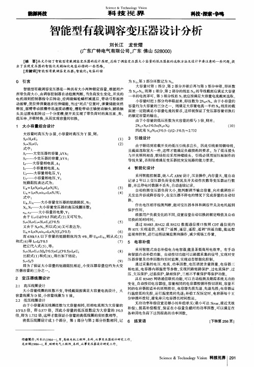
S y = 3 I y  ̄ U Y 式中:
( 2 )
S d - 一 大变压器 的容量 , k V A: S 广 小变压器的容量 . k V A: I r 一 大容量相电流 , A ; I 广 _小容量相 电流. A ; U 一 大容量相 电压 . v: u Y . 一 小容量相 电压 , v : 短路阻抗表达式为 :
U 。 [ I a x N d x / e ,  ̄ = I d x N d 钿d U Y k o c I y x N y x / e I Y × NY 2 / UY ( 3 ) ( 4 )
由于联结到有载开关 的低压引线多且长 .因此引线要用铜母线 . 且截面选取宜大一些 , 这样才能满足负载损耗的要求。为 了低压接头 与开关顺利相连 . 联结处应采用伸缩接头。引线必须用层压板制作的 导线夹紧 . 否则很难满足变压器抗突发短路 的能力要求
出 了 实现 变 压 器 的 智 能化 及 精 细 化 电容 补 偿 的 一 些 思路 。
【 关键 词】 智能型有载调 容变压器; 智能化 ; 电容补偿
O 引言
智能型有载调容变压器是一种具有大小两种额定容量 . 根据用户 所带负荷大小 , 由调容控制器 自动检测判断。 当负荷发生变化 , 开关的 电机得到控制器指 令后转动 . 经两级蜗轮 蜗杆减速后 . 带动 弓形 板推 动摇 臂 , 使拉伸弹簧逐步拉伸储能 . 当过“ 死 点” 位置时 , 弹簧储 能突然 释放 , 摇臂带动拔槽件 迅速拔动槽轮 , 槽 轮带 动主轴使动触头, 辅 助触 头及 过渡电阻转过一个 分度槽 , 使开关实现 了带 负荷 时的高压星 、 角, 低压 串 、 并 联转换 , 从 而实现容量 的切换 。
U Y k l y x Nv x / e t y = l y x N a 2 / ( U J 3 " 0 . 5 ) ( 6 ) 而6 3 0 k V A以下容量 的短路 阻抗均为 4 %, 即u = U , 则从 式( 3 ) 和式 ( 6 ) 得I v = I d 3 0 . 5 ( 7 ) 5 电容 补 偿 把它代入式( 5 ) , 得: 采用智 能式动态补偿 电力 电容器 . 能显著提高用电效率 有手 动 S y = 3 I v x U y = 3 ( I # ' 3 0 . 5 ) x W( 3 " o . 5 ) = I d x U d ( 8 ) 和智能 自 动补偿功能 自 动投切功能可 以跟据采集 的信号 . 实现对变 比较式( 1 ) 和式( 8 ) , 得出如下结 论 : 压器容量及功率 因数 的实 时监测 . 实现动态智能化控制。 S v = S d / 3 ( 9 ) 通过采集 的电压 、 电流 、 功率 因数 , 电压谐波含量 测量 , 电容器三 即为了保 证大小 容量 的短路 阻抗相 近 . 小 变压器容量应 约为 大变 相 电流, 电容 器 内部温度等 参数 , 实现 回路 短路保护 、 过电流保护 、 过 压器容 量的三分之 一 压、 欠压保护 , 过温保护 , 缺相保护 . 三相不平衡 保护等保 护功 能。 2 变 压 器 线 圈设 计 具有 R S 4 8 5网络通信联机功能 . 可 以自动检测及跟踪系统无 功的 变化 . 自动投切 电容器组。 容量相 同的电容器按循环投 切原则 . 容量不 2 . 1 高压线 圈设计 同的 电容器按适补的原则投切。 电容器先投先退 、 先退 先投 : 电容器运 大小容量线 圈的匝数不变 . 导线截 面按满足 大容量电流设计 大 行温度低的先投 , 运行温度高的先退 : 补偿工况恒定时 , 电容器每十五 容量线 圈为 D接 . 小容量线 圈为 Y接 分钟循环投切 , 避免单只电容器长时间投运。 2 . 2 低压线 圈设计 无功功率补偿设置足够小 的补偿单元 ( 最小 可达 5 k v a r . 接近无级 由于小容量高压线 圈匝数与大容量相 同. 而相 电流则为大容量 的
PCS-222T说明书

非电量4跳闸投入
0,1
16
非电量5跳闸投入
0,1
17
非电量6跳闸投入
0,1
18
非电量7跳闸投入
0,1
19
非电量8跳闸投入
0,1
20
非电量9跳闸投入
0,1
21
非电量1经非电量10闭锁
0,1
5.4 PCS-222T
序号
定值名称
定值范围
整定步长
1
档位个数
0—26
2
档位编码
0-3
3
档位防抖时间
0—60000Ms
16
串口A通讯协议
0~2
17
串口B通讯协议
0~2
18
远方修改定值
0,1
19
监视方向闭锁
0,1
20
打印波特率
4800,9600,19200,38400
21
自动打印
0,1
22
高速打印
0,1
23
外部时钟源选择
PPS(RS-485)
IRIG-B(RS-485)
PPM(DIN)
1.装置编号:字符串类型,用于标识装置本身。
电快速瞬变脉冲群抗扰度:IEC61000-4-4(GB/T17626.4)4级
振荡波抗扰度:IEC61000-4-12(GB/T17626.12) 3级
静电放电抗扰度:IEC61000-4-2(GB/T17626.2)2级
工频磁场抗扰度:IEC61000-4-8(GB/T17626.8)5级
脉冲磁场抗扰度:IEC61000-4-9(GB/T17626.9)5级
3.2
从变压器本体来的非电量信号(如瓦斯信号等)经过装置重动后给出中央信号、远方信号、事件记录三组接点,同时装置本身的CPU也可记录非电量动作情况。对于需要延时跳闸的非电量信号,由装置经过定值设定的延时起动装置的跳闸继电器,而直接跳闸的非电量信号直接起动装置的跳闸继电器。其原理可分别参考图3.3.1,3.3.2,3.3.3。
调压器说明书
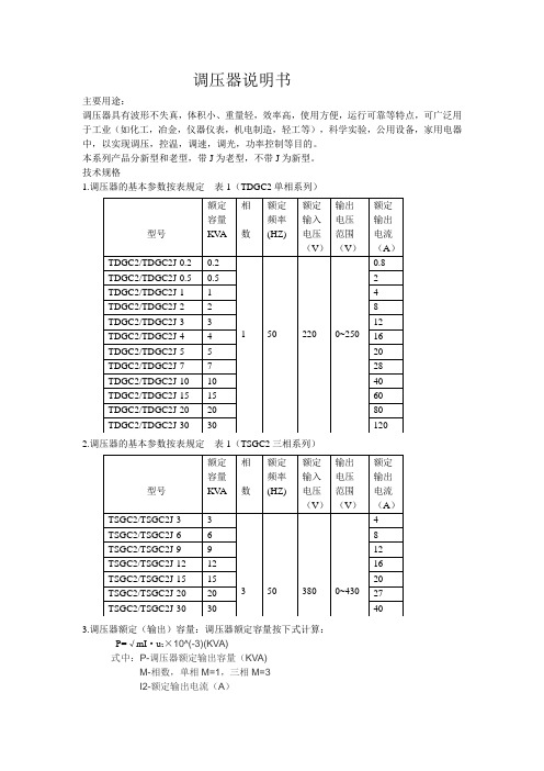
调压器说明书主要用途:调压器具有波形不失真,体积小、重量轻,效率高,使用方便,运行可靠等特点,可广泛用于工业(如化工,冶金,仪器仪表,机电制造,轻工等),科学实验,公用设备,家用电器中,以实现调压,控温,调速,调光,功率控制等目的。
本系列产品分新型和老型,带J为老型,不带J为新型。
技术规格1.调压器的基本参数按表规定表1(TDGC2单相系列)2.调压器的基本参数按表规定表1(TSGC2三相系列)3.调压器额定(输出)容量:调压器额定容量按下式计算:P=√mI·u2×10^(-3)(KVA)式中:P-调压器额定输出容量(KVA)M-相数,单相M=1,三相M=3I2-额定输出电流(A)U2-最大输出电流(V)(三相为线电压)过载(%)不超过(分钟)20 6040 3060 64、调压器绝缘等级为A级,线圈平均温升限值为60℃5、过负荷能力,调压器允许短时间超过额定输出电流值。
但不能超过表2的规定基本原理与主要结构1.基本原理:调压器电刷借助于手轮主轴和刷架的作用,言线圈的磨光表面滑动,变化电刷接触位置、改变一次和二次线圈匝数比,以达到调压的目的。
2、主要结构:①单位结构:单相0.2KV A~10KV A调压器为调压单元结构,一个上端面具有一定宽度的磨光表面的线圈固定在工程塑料的底座上,接触组的电刷在弹簧压力下与线圈的磨光表面金梅接触,转动手轮带动电刷在线圈磨光表面上滑动进行调压。
单元调压器一般为台式,外面有防护通风罩。
单元调压器绕组联接如图一所示:注:图中U1-输入电压(伏)U2-输出电压(伏)D-电刷②单相组装结构,单相大容量调压器是由几个相同规格的单元组装而成,各单元的电刷接触组装在同一主轴上,线圈输入端并联连接平衡电抗器,以平衡单元间电流分布并抑制环流。
单相大容量调压器绕组联接如图2.图3所示:U1-输入电压U2-输出电压D-电刷DK DK1 DK2是平衡电抗器③三相组装结构:三相调压器由三个相同规格的单元同轴组装而成。
PCS-222TU_X_说明书_国内中文_标准版_X_R2.01_(ZL_ZNKZ0201.1208)

我们定期仔细检查本文档中的内容,在后续版本中会有必要的修正。 资料相关,请联系:
但不可避免会有一些错误之处,欢迎提出改进的意见。
电话:025-87178185、传真:025-8718208
我们保留在不事先通知的情况下进行技术改进的权利。
电子信箱:nr_techsupport@
警示!
接地 装置的接地端子必须可靠接地。
运行环境 该装置只允许运行在技术参数所规定的大气环境中,而且运行环境不能存在不正常的震动。
额定置的额定参数。
印刷电路板 在装置带电时,不允许插入或拔出印刷电路板,否则可能导致装置不正确动作。
外部回路 当把装置输出的接点连接到外部回路时,须仔细检查所用的外部电源电压,以防止所连接的回
警告!
电气设备在运行时,这些装置的某些部件可能带有高压。不正确的操作可能导致严重的人身伤 害或设备损坏。
只有具备资质的合格专业工作人员才允许对装置或在装置临近工作。工作人员需熟知本手册中 所提到的注意事项和工作流程,以及安全规定。
特别注意,一些通用的工作于高压带电设备的工作规则必须遵守。如果不遵守可能导致严重的 人身伤亡或设备损坏。
警告! 意味着如果安全预防措施被忽视,则可能导致人员死亡,严重的人身伤害, 或严重的设备损坏。
警示! 意味着如果安全预防措施被忽视,则可能导致轻微的人身伤害或设备损坏。 本条特别适用于对装置的损坏及可能对被保护设备的损坏。
警告!
为增强或修改现有功能,装置的软硬件均可能升级,请确认此版本使用手册和您购买的产品相 兼容。
1.1 应用范围 ...........................................................................................................................1 1.2 保护配置和功能 ................................................................................................................1 1.3 测控配置 ...........................................................................................................................1 1.4 性能特征 ...........................................................................................................................1 1.5 产品执行标准 ....................................................................................................................2 第 2 章 技术参数 ............................................................................................................................5 2.1 电气参数...........................................................................................................................5 2.2 机械结构 ...........................................................................................................................6 2.3 环境条件参数 ....................................................................................................................6 2.4 通信端口 ...........................................................................................................................6 2.5 型式试验...........................................................................................................................7 2.6 认证 ..................................................................................................................................8 2.7 故障录波和事件记录.........................................................................................................8 2.8 主要技术指标 ....................................................................................................................9 第 3 章 保护原理 .......................................................................................................................... 11 3.1 概述 ................................................................................................................................ 11 3.2 非电量保护原理 ..............................................................................................................12 3.3 RTD 直流测量原理...........................................................................................................14 3.4 直流测量 .........................................................................................................................14 3.5 档位测量 .........................................................................................................................14 3.6 滑档跳闸 .........................................................................................................................15 第 4 章 硬件描述 ..........................................................................................................................17 4.1 概述 ................................................................................................................................17 4.2 装置面板布置 ..................................................................................................................17 4.3 结构与安装......................................................................................................................18
自动调容调压变压器参数
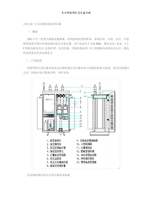
ZGS13—Z自动调容调压变压器一、概述ZGS13-Z-型变压器就是根据城、农网建设改造得要求,本着经济、合理、安全、可靠得原则设计得自动调容调压组合式变压器。
该产品适用于交流50Hz、额定电压10/0、4kV智能化配电台区,结构合理、实用性强、节能效果显著,对于保障配电系统安全运行,提高供电质量具有深远得意义.二、产品构成智能型组合变压器本体由自动调容调压变压器本体与智能控制单元组成,采用自然通风方式,结构应设计紧凑合理,双杆安装。
自动调容调压组合式变压器本体构成变压器控制单元构成三、主要特点1、自动调压功能变压器本体油箱内配置调压开关,在电压波动时自动调节电压高低,使变压器低压侧电压输出稳定在合格范围内,提升供电质量。
调压分接范围为额定电压得±5%。
2、自动调容功能变压器本体油箱内配置调容开关,在用电负荷时段性高峰时自动将变压器调整到大容量档运行,在用电负荷时段性低谷时自动将变压器调整到小容量档运行,有效降低变压器损耗。
3、微机保护方式得过流及短路保护功能线路或负荷出现过流、短路故障,变压器内负控开关自动跳闸并远程上传报警信息,过流与速断保护应采用微机保护方式,保护定值连续可调,便于配合各级保护设备进行定值得精确整定,保证故障线路停电不波及上级开关跳闸。
4、双级漏电保护功能低压配电管理终端具有漏电保护功能,与变压器本体内永磁机构真空开关与配电出线断路器配合,具备进线与出线双级漏电保护功能。
5、就地及远程电动停送电功能变压器本体油箱内配置永磁机构真空开关,可实现就地电动停送电、远程无线遥控停送电功能。
6、无功补偿功能要求变压器智能监控单元内配置低压无功精细补偿隔室,实现级差不大于1kvar得分相分级精细无功自动补偿,采用共分结合优化补偿方式,投切开关采用同步编码开关组,具有投入无涌流,切除无弧光,投切无谐波污染得特点。
7、电能计量功能设置独立密封得计量隔室,密封得主进线直接进入计量隔室,通过母排进入其它隔室,配置一块三相计量接线盒,预留两块三相电子式电表安装位置.电表与计量电流互感器由用方自备.8、GPRS无线“四遥”与配电监测变压器智能监控单元包含支持GPRS无线通讯与配电监测功能得低压配电管理终端,可将监测数据与运行状态实时远传给后台管理系统,支持GPRS方式遥控、遥信、遥调与调测“四遥”功能.四、主要技术参数五、使用环境1)海拔高度:≤2000m2) 环境温度:—25℃ ~ +45℃,24小时内平均温度不超过+35℃;3) 相对湿度:≤90%(25℃)4)抗震能力:地面水平加速度 0、3g,地面垂直加速度 0、15g同时作用持续三个正弦波,安全系数 1、675) 最大风速:≤35m/s6)安装位置:户外7)污秽等级:≤III级;六、外形尺寸图及安装示意图自动调容调压组合式变压器本体外形尺寸图自动调容调压组合式变压器安装示意图。
变压器样本参数
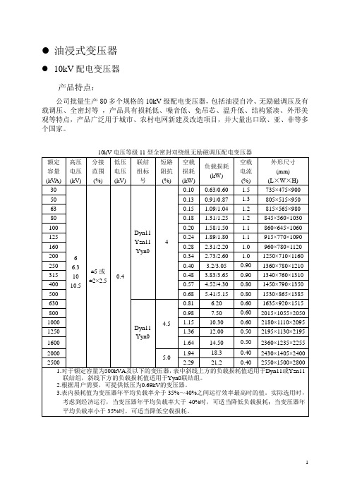
●油浸式变压器●10kV配电变压器产品特点:公司批量生产80多个规格的10kV级配电变压器,包括油浸自冷、无励磁调压及有载调压、全密封等,产品具有损耗低、噪音低、免吊芯、温升低、结构紧凑、外形美观等特点,产品广泛用于城市、农村电网新建及改造项目,并大量出口欧、亚、非等多个国家。
立体卷铁心变压器产品特点:三维立体卷铁芯变压器是近年来发展起来的新型节能配电变压器,该变压器采用传统冷轧硅钢片材料,在磁路结构上进行了特殊布置,使硅钢带的高导磁方向与磁路完全一致,三个心柱呈等边三角形立体排列,三相磁路长度相同,使其具有降低空载损耗、节省材料、减少噪声、抗短路能力强等优点,比S11型同容量变压器,空载损耗平均降低30%,空载电流下降70%,噪声下降10~25dB型号说明:电压等级kV 额定容量kV A 立体 卷铁心 全密封 13型 三相非晶合金配电变压器产品特点:非晶合金配电变压器是采用非晶合金作为导磁材料所制造的一种配电变压器,可取代硅钢片铁芯的变压器而广泛用于配电系统,空载损耗比S9型变压器降低75%左右,是目前节能效果最理想的配电变压器。
本产品特别适用于电能不足、负荷波动大以及难以进行日常维护的地区,本产品采用全密封结构,绝缘油不受外界大气的污染,是城乡广大配电网络中理想的配电设备。
高燃点变压器产品特点:高燃点绝缘油变压器是目前世界广泛应用的城网专用变压器,适用于城镇住宅区、宾馆商厦、医院、实验室、学校、剧院、石油化工、车站地铁、机场、矿井等要求安全防火性高、噪声低等重要场所,属于新型安全、防火、环保节能型变压器。
兼顾了油浸式变压器和干式变压器的共同优点,比普通油浸式变压器更安全,比干式变压器更实惠,成为继普通油变、干变之后的又一新型变压器,高燃点绝缘油变压器的推广应用将成为中国变压器技术领域的又一次产业革命。
整流变压器公司生产的ZS系列整流变压器用作整流装置的电源变压器,其作用是向整流器提供交流电源,整流器再将交流电变换为直流电,从而进行直流供电。
有载调容变压器说明书
一、适用范围本说明书适用于额定频率为50Hz,电压等级为10kV,三相额定容量为100(30)kVA~630(200)kVA的有载自动调容配电变压器。
二、术语解释S11-M.ZT型有载自动调容配电变压器是一种具有大小两种额定容量,根据用户所带负荷大小由自动调容控制器自动检测判断,并通过特制的有载调容开关,在变压器不停电状态的下,对变压器两种容量进行自动切换,实现对运行过程中变压器容量大小自动调整,从而实现两种额定容量运行方式自动转换的配电变压器。
三、使用场所S11-M.ZT型有载自动调容配电变压器适用于用电季节性强、负荷波动大、用电集中、年平均负载率低的场所。
在我国农村用电主要集中在夏、秋两季,其余季节主要是照明用电,在农忙季节,变压器过载运行现象严重,而在用电淡季,负载率低,又出现了“大马拉小车”的现象,所以载调容配电变压器特别适用于农网改造中;另外,也适用于白天和晚上用电负荷差异较大的住宅小区和常白班的企事业单位。
四、基本原理有载自动调容配电变压器在大容量时,三相高压绕组接成三角形接法(角接),低压绕组并联结构;在小容量时,三相高压绕组接成星形接法(星接),低压绕组串联结构。
高压绕组的星--角转换和低压绕组的串-并联转换,均由有载调容开关来完成,而有载调容开关的切换是由自动控制器根据检测的负载大小情况来决定的。
当变压器由大容量转换为小容量时,由于线圈匝数增加了1.7倍,铁心磁通密度大幅度降低,硅钢片单位损耗变小,空载损耗和空载电流也大幅下降,从而大大降低了变压器的空载无功损耗(小容量时的空载无功损耗小于大容量时损耗的十分之一)和有功损耗(小容量的空载损耗小于大容量损耗的三分之一),达到了节能降耗的目的。
五、变压器本体结构特点1、铁心变压器铁心结构为叠片式结构,采用优质冷轧取向硅钢片,阶梯形三级全斜接缝,不冲孔,改善了磁路结构,增大了接缝面积,减少了接缝处的磁通阻力,与两级接缝相比,空载损耗可降低5%,空载电流可降低20%~30%。
调容调压变压器说明书

目录Contents概述技术数据变压器原理及结构主要功能外形尺寸及安装示意订货须知运输、验收和保管安装、维护和检修随机文件1 1 3 6 913 14 15 12自动调容调压变压器1、概述ZGS11-Z型自动调容调压组合变压器(以下简称变压器)是根据城、农网建设改造的要求,研制开发的一种智能化节能型新型设备。
它可根据用户实际运行电压高低、负荷大小、电能质量优劣等实际情况,利用组合式调压调容开关改变变压器线圈各抽头的接法和负荷开关状态,使变压器在不同分接头、额定容量间自动切换,实现自动调容/调压、远程负控、三相有功不平衡调节等功能,还可利用分级精细自动控制进行无功补偿,从而降低空载损耗,实现变压器的节能运行,达到节能目的。
该产品适用于交流50Hz、额定电压10/0.4kV、容量500kVA及以下的配电台区,主要应用于季节性或昼夜负荷变化幅度较大的城市居民区、商业区、工业区和农村电网。
具备智能化操控、结构合理、实用性强、节能效果显著等特点,对于保障配电系统安全运行,提高电网供电质量具有深远的意义。
2、技术数据2.1 型号的表达方式ZG S 11 - Z - □(□)·/ 10 I设计序号电压等级(kV)额定容量(kVA)终端型性能水平代号三相组合共箱式注:□(□)现有额定容量组合方式为500(160)、315(100)、200(63)12.2正常工作条件2.2.1变压器可以在以下温度和湿度环境下正常工作:最高温度+45℃最低温度-25℃(严寒地区-30℃)平均温度24小时内平均温度不超过+35℃日平均相对湿度不大于95%月平均相对湿度不大于90%2.2.2最大风速不超过35m/s(相当于风压小于700Pa)2.2.3空气污秽程度不大于Ⅲ级2.2.4安装场所海拔高度≤2000米2.2.5抗震能力地面水平加速度0.3g,垂直加速度0.15g,同时作用持续三个正弦波,安全系数1.672.2.6户外安装,但不适用于火灾、爆炸、化学腐蚀及剧烈震动场所。
箱变操作使用说明
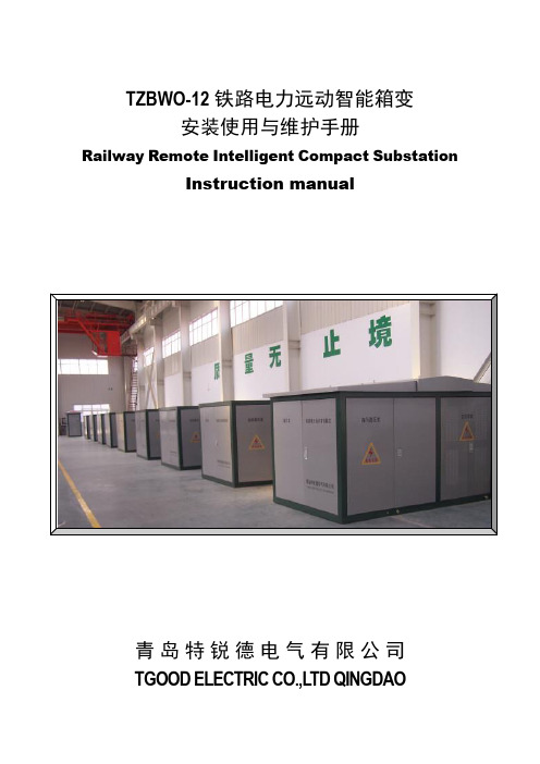
TZBWO-12铁路电力远动智能箱变安装使用与维护手册Railway Remote Intelligent Compact SubstationInstruction manual青岛特锐德电气有限公司TGOOD ELECTRIC CO.,LTD QINGDAO始终安全第一Safety first-always!在开关设备安装使用前请先仔细阅读本说明书That’s why our instruction manual begins with these recommendations箱式变电站安装于户外场所。
Compact substation install outdoor suitable for electrical equipment.确保由专职电气人员进行安装、操作和维护。
Ensure that installation,operation and maintenance are carried out by specialist electricians only.必须保证现场电气设备的联接条件和工作规程的适用和安全性。
Comply in full with the legally recognized standards(DIN VDE/IEC),the connection conditions of the local electrical utility and the applicable safety at work regulations.有关开关设备的一切操作,都要遵守说明书中的相应规定。
Observe the relevant information in the instruction manual for all actions involving switchgear and switchboards.危险Danger要特别注意说明书中标有这个危险标志的注意事项。
Hitachi Energy变压器产品说明书

TransformersAdvancing a sustainable energy future for allThe journey continues with the world’s largest installed baseWindstar transformerFor large offshore wind turbineSubsea transformerFor depths up to 3,000 metersHVDC transformerWorld’s most powerful1,100 kilovolt (kV) transformerSmart transformersEnabling your digital future130 years of groundbreaking solutionsToday wherever you are a transformer is powering you−Transformers are fundamental to electricalnetworks, they enable efficient and safe power transmission and consumption−With increasing complexity in the grid,transformers are also increasingly used for improving power quality and network managementTransmission and distributionMetals & Mining, Oil & GasIndustry MobilityCommercial and InfrastructurePower generationAbout Transformers Business~14,000 employeesRevenues in ~ 90countries ~ 60Facilities around the worldWith ~ 30 servicecentersComplete rangeof power anddistributiontransformers,componentsand services Voltage rangeup to 1,200 kV ACand 1,100 kV DCAbout Transformers Business -World’s largest installed baseDistribution transformersDry transformersPower transformersTraction transformers>325,000>75,000>2,000,000>30,000Reactors>4,000HVDC transformers>700Complete range of Transformers, Components and ServiceDigitalization of transformers: TXpert EcosystemOnline and standalone intelligenceOpen and scalableDistributionTransformersPower TransformersHVDC ConverterTransformersDry TransformersTraction TransformersIndustry & special applicationsTransformers Insulation, components &digital sensorsTransformerServicePower Transformers –Production UnitsUSACrystal SpringsItaly MonseliceFinland Vaasa Colombia PereiraTurkeyIstanbul (Kartal)Vietnam HanoiChina ZhongshanPoland LodzGermany Bad Honnef Thailand BangkokUSASouth BostonIndia VadodaraCanada Varennes China ChongqingSpain CordobaSweden LudvikaBrazil GuarulhosDistribution Transformers –Production UnitsDry FactoriesLiquid-filled DTR factories Traction FactoriesDTR + DRY LocationsColombiaPereiraBrazilBlumenauUSASpainGermanyPolandSwitzerlandTurkeyIstambul(Dudullu)EgyptCairoSouthKoreaChinaIndiaVadodaraSouthAfricaJohannesburgVietnamHanoiRussiaKhotkovo(Moscow)CanadaQuebec CityDatongCheonanSecheronTrasforZaragozaJeff CitySouth BostonShanghaiHefeiLodzBrilonBlandTransformer Service UnitsAmericasBrazil, Canada, Chile, Colombia, Mexico, Panama, Peru, USA EuropeFinland, France, Germany, Italy, Norway, Poland,Spain, Sweden, Switzerland, Turkey, UKAsia, Middle East, AfricaAustralia, China, India, Qatar, UAESaudi Arabia, Singapore, South Africa, ThailandNew forces are driving the change in today and future transformer design RenewablesEnergy efficiency Safety and Environment Service and Intelligence Ex: Low-loss transformersEx: TCO calculatorEx: Voltage regulatorsEx: Booster transformersEx: 66 kV specialty transformerEx: Natural Ester oilEx: Dry-type transformers, reactors and bushingsEx: CoreSense familyEx: CoreTec™EX: TXpert™02 03 01 0405 06Security andResilienceNew boundariesEx: AssetShield™ballistic protection systemEx: Dry bushing (O Plus Dry)Ex: TXtreme™Ex: 1,100 kV converter transformerEx: Effilight® traction transformerEx. Dry transformers up to 72.5 kV–Maximizing financial savings–Reducing CO2 emissions–Integrating more green energy into the grid–Superior engineering and design for grid complexity–Insulating fluids and materials–Oil to dry conversion of transformers and components–Condition-based maintenance–On-line monitoring–Multiple intelligent electronic devices–Onsite vulnerability assessment, hardening, monitoring,rapid repair, rapid replacement–UHV AC-DC transformers–Submersible solutions–Low noiseTransformers —Key Customers SegmentsDatacenters−Reliable partner for global Datacenter customers −Ensuring world class the stability and reliabilityRenewables−Integrating more green energy into the grid −Superior engineering and design for grid complexityUtilities−Partner of choice for utilities with a long-history −Product and Service offering to serve the most complex customer requirementsIndustries−Long-term collaboration e.g. O&G, Pulp and Paper globally −Global network to provide offering worldwideTransportation−Worlds largest traction transformers manufacturer −Wide transformers offering for Marine industry0203010504VariousC O M P O N E N T STXpert TM Ecosystem Unlocking the power of the digital gridToday TomorrowPower systems of the future —an evolutionary visionIncreasing complexity of the grid will impact transformers in new ways, for example:Increasingly overloaded based on generation mixIntegration of renewables leads to reverse and dynamic power flowsDynamic load profiles and increasing risk of outagesOur rich history of leadership in transformers and digitalization2016ABB continues to innovate in digitalization, launching AssetShield ™ballistic detection and response solutions1990sFirst digitalcontrol introduced for transformers1890Jonas Wenström, a Swedish engineer from ASEA(later ABB) invented the world’s firstcommercial three-phase electric power system, including the three-phase transformer2020 and the FutureTXpert TM Ecosystem , Machine learning Artificial intelligence to maximize transformer performanceA truly interconnected smart grid emerges1980Fiber optic temperature monitoring pioneered by ABB2013Asset Health Center enterprise assetmanagement solution is introduced, today known as Ellipse®2015CoreSense ™DGA sensors provide continuous monitoring for transformer faults2017ABB launches TXpert ™the world’s first digital distributiontransformer and CoreSense ™M10 multi-gas DGA2018Launch of the TXpert TMEnabled Power Transformer sets the digitalization benchmark.TXplore ™Safe, fast and internal robotic inspection2001Transformer Electronic Control (TEC )introduced to enable condition monitoring2010Self Dehydrating Breather eSDB with digital tracking is launched2019ABB to launch TXpert ™DRY the world’s first digital dry distribution transformer and APM EDGE Station level solution.2005Remote monitoring introduced with TEC version 2TXpert TM Ecosystem —Products, Software, Services, SolutionsPower or Distribution transformer TXpert™ReadySensorsTXpert™Hub−Reduced costs and risks−Optimized operations−Extended life-cycle expectancy−Enhanced environmental performance −Full ecosystem−Digital distribution & substations−Asset performance Management−Virtual site management−Modular−Scalable−Future-proof−Manufacturer agnostic Unlocking the potential of digital gridTransforming performance The future is openDigitalization of transformers for increasing life expectancyLevels and trendsProbability of Failure (PoF)Expert systemExtend asset lifetime thanks to online monitoring and condition-based maintenanceCheck different parameters, levels and trends while comparing them to international standards like IEEE or IEC.Give maintenance recommendations based on design parameters, historical trends and on-line data.Classify each transformer by its PoFto prioritize maintenance work.Online MonitoringTransformers for a sustainable worldWe enable access to electricity with a focus on sustainabilityDecarbonizationResponsible resource utilizationSustainable infrastructurePeople andecosystems safetyWe are committed to contributing to the United Nations Sustainable Development GoalsCentralized generationEnd consumersDistributed generationFast charging 50 –350 kW3 –7 kWMV/HV MV/LVHV lineMV line LV lineIsolated 3 –350 kW10 –20 kWThe total cost of ownership tool Typical savings for a 40 MVA, 112 kV transformerReducing total costs for business and the environmentDifference between eco-efficient and traditional designsEnergy savings/year -91,542 kWhCO 2emission reduction/year -38 tonnesAs an example, the European Union alone has an estimated 4.5 million distribution transformers which could avoid 38 TWh of electrical losses and 30 million tonnes of CO 2emissions every year via energy efficient transformers.Circularity in transformersCopperAluminumSteelOil (new development)Transformers can be ~99% recyclable and reusableResponsible sourcingDesigns built with TCO(total cost of ownership)Prolonged lifetime with conditionmonitoring, life-assessment andpreventive maintenance services››››EconiQ TM transformers: co-creating sustainable solutions Your partner in the sustainability journeyacross the transformer life cycleWith transparency on environmentalimpacts using science-basedmethodologiesSolutions for decarbonization, enhancedsafety, protecting ecosystems andresponsible resource useDriving energy efficiency for reducing GHG emissionsProud to be active partner with initiatives worldwide for driving higher energy efficiency standards in transformers e.g.Partnering worldwide with other key Standardization Committees: IEEE, cigre and country organizations(European Committee for Electrotechnical Standardization)Currently holding the Secretariat for Transformers Committee CLC TC 14International Electrotechnical CommissionCurrently holding Chair of Transformers Committee IEC TC 14Providing technical expertiseto United4Efficiency Program (Under leadership of UNEP)Transformers and services —partnering with our customers for the grid of the futurePowerful transformers for bulk power transmissionAbout 800 million peopleworldwide do not haveaccess to electricity.The 3293 kilometers longChangji-Guquan link in China iscapable of transmitting 12,000megawatts, that is enough powerfor about 12 million people in Chinawith about 40% lower losses(1).Hitachi Energy 800-ton 1100 kVUHVDC transformers facilitate powerflow across this link from the sendingstation.Grid interconnections with HVDC converter transformers HVDC Light®transmission system,Norway-Germany1,400 MW, ±525 kV, 623 kilometers.TenneT in Germany and Statnettin Norway.Called “The green-link” it will enabletrade in hydro power from Norway andsolar and wind power from Germany.HVDC Converter and AC transformersfrom Hitachi Energy in both countries.Compact design for challenging transportation.GERMANY NorwayGermanyLarge scale integration of renewables with digital transformers Mainstream RenewablePower -Andes RenovablesSupporting Chile’s aim to get 70% of itselectricity from renewables by 2050.12 wind and solar projects, 1500 MWcapacity –electricity for 1.3 million people based on per capita usage in ChileTXpert TM Enabled Power Transformers for grid integration:−Designed to never go offlineunexpectedly−Enable preventive maintenance−Remote management in far-flung locationsSOUTHAMERICACHILECkani109 MWTchamma157 MWCerro Tigre 185 MWPampa Tigre100 MWLianos del Viento160 MWRio Escondido 145 MWValle Escondido105 MWSacro170 MVCuel33 MWAlena84 MWAuora129 MWPuelche Sur156 MWInterContinental Robertson Quay Hotel, Singapore−Minimize out-age risk−Maximize return on investment−Optimize operations with condition-based maintenance −Enhanced safety of personnel and environmentTXpert TMEnabled dry transformerIncrease in book value of the transformer at the end of 20 years100%Increase in the lifespan of the transformer50%Reduction in the failure rate40%It is projected thatby 2050 more thantwo-thirds of the world population will live in urban areas.75 dry transformers from Hitachi Energy are installed in the Burj Kalifa, Dubai, eliminating risks of oil spills and safety hazards.Enhancing safety with TXpand A rupture resistant transformer solution:−Capable of absorbing the expansion caused by gases generated during a 20 megajoule arc−Minimizing oil spillage and predictably channeling what little oil escapes for easy containment−Risk of unplanned and long outages are reduced−The TXpand transformer technology has been co-created with our partner Hydro Quebec, CanadaEliminating hazards of oil-spills Dry-type transformers−100% oil-free to minimize environmental contamination and fire hazardEster insulation fluid−Biodegradable as designated by the Environmental Protection Agency (EPA)−Reduced fire risk with 355˚C fire-point for natural esters as compared to 170˚C for mineral oil−Available in power and distribution transformer up to 420 kV / BIL 1425 kV −Supplied about 200 power transformers and 12,000 distribution transformers with ester fluidsEnhancing safety, reducing environmental incidents Reducing incidents withTXplore TM−No, or very little, oil needs to behandled−Eliminates the risk of a personentering confined space−Inspection can begin immediately aftertaking an outage−Significant reduction in outage timeCircularity in transformersCircularity is present already in the transformers industry; but considering that almost 99 % of the transformer materials could be reused or recycled, a lot more can be done towards circularity.A recent example is the Stena recycling and Hitachi Energy case in Sweden where old transformers will be disposed reusing or recycling about 99% of the material, comprising 64% material recycling, 35% clean, low emissions efficient incineration for energy and the balance 1% as disposed waste.The new normalVirtual Factory Acceptance Test (FAT) -Ensuring full transparency and trustCity A, Country 1 CustomerCity B, Country 2Hitachi Energy factoryInternetTest areaControl roomNo travelSaves time, effort and costsSimple and easy to useTransparentHelps in maintainingtimely deliveriesUtilizing the power of virtual technologiesAugmented reality powered visual inspection by experts 24/7−See with the eyes of our experts who will guide your hands−Check status of alarms andmonitoring devices to detect defaults−Access transformer virtualinstallation support Fast service solutions No travelGlobal specialistsLive troubleshootingCustomer at site Hitachi Energy expert。
自动变压器交流设备说明书
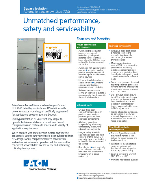
Unmatched performance, safety and serviceabilityProven performance and reliability•Automatic bypass switch provides operational redundancy and quickly restores power to criticalloads when the ATS has been isolated for test or removed for service•Automatic, non-automatic and manual A operation modes provide multiple methods of transferring the load between power sources•UL 1008 listed short-circuit and short-time B withstand closing current ratings maximize system reliability •Tethered remote controlallows an operator to initiate a non-automatic transfer outside the arc flash boundaryEnhanced safety•Unique three-door,compartmentalized design provides steel barriers protecting workers from energized components •All doors open/closeindependently eliminating unnecessary exposure to adjacent compartments •Integral safety interlocks automatically open the main contacts prior to the ATS or automatic bypass switch being isolated for test or removed for service•Rear shutters B automatically close to isolate bus stabs when the ATS or automatic bypass switch is being racked outEaton has enhanced its comprehensive portfolio of UL T 1008 listed bypass isolation ATS solutions with power contactor type designs specifically engineered for applications between 100 and 3000 A.Our bypass isolation ATSs are not only simple to operate, but also available in a broad selection of configurations and features to meet a wide variety of application requirements.When coupled with our extensive custom engineering capabilities, Eaton’s innovative three-door bypass isolation ATS design, robust compartmentalized construction, and redundant automatic operation set the standard for concurrent serviceability, worker safety, and optimizing critical system uptime.Improved serviceability•Innovative three-door design eliminates the need to schedule shutdowns for routine test, inspection or maintenance•Maintenance isolationswitch (MIS) permits service personnel to electricallyisolate control compartment elements and minimize shock hazard prior to beginning work —without disruption to critical loads•Control compartment door and adjoining electrical panel slide forward from the enclosure to provide easy access to wiring and components•Dual drawout design allows the ATS or automatic bypass switch to be disconnected from the electrical bus and isolated in cell for regular testing as prescribed by code (NFPA T 70, 99, 110)•Testing of isolated switch can be performed while ATS or automatic bypass switch is in automatic or non-automatic mode of operationSimplified installation and integration•Field-configurable terminals allow cable ingress at top/ bottom for power source and load connections•Internal floor-mount anchors minimize footprint andfacilitate efficient integration into an equipment lineup •Seismic certified to OSHPD, CBC, IBC and UBC•Front and rear access availableFeatures and benefitsA Manual operation (unloaded) provided for all product configurations; manual operation (under load)available for select catalog configurations.B Feature/rating available for select catalog configurations.Bypass isolationContactor type, 100–3000 AOpen/closed transitionDesign featuresDual automatic technologyEaton’s unique design includes an automatic bypass switch and an ATS within a single assembly to provide redundant automatic operation and uninterrupted power to critical loads.Optimize reliability and maximize uptimeThe automatic bypass switch and ATS can be racked out and isolated in cell for regular testing to ensure the entire bypass isolation transfer switch is maintained in proper operating condition.Facilitate scheduled maintenance The automatic bypass switch or ATS can be withdrawn for visual inspection andcompletely removed for bench testing without impacting automatic operation.Enhance worker safetyThe upper and lower doors can be operated independently, maintaining electrical isolation of the energized compartment.T esting… it’s as easy as 1-2-3 A three-step operator interface helps simplify testing procedures of the automatic bypass switch or ATS when racked out to the isolated position.Safe and serviceableEngineered for safety, athree-door compartmentalized construction coupled with an MIS allow personnel to perform maintenance on the bypass isolation transfer switch while energized.To mitigate shock hazard, the MIS can be placed in the maintenance position prior to opening the door, electrically isolating elements of the control compartment from system and control voltage.Once isolated, the control compartment door can beopened and adjoining electrical panel slid forward, allowing a technician to safely inspect, troubleshoot and replace electrical components.Upon completion, the door is closed and MIS returned to the normal operation position.Multiple operation modes Local operation is possible in the following modes:• Automatic • Non-automatic •Manual AIn Automatic mode, the transfer switch is self-acting, and atransfer is automatically initiated by the intelligent controller logic.In Non-Automatic mode, a transfer is initiated by theoperator using a door-mounted selector switch or an optional tethered remote control.In Manual mode, a transfer is initiated by the operator using controls mounted directly on the automatic bypass switch or ATS.Alternatively, a transfer can be initiated remotely via an HMi remote annunciator controller or network communication.Automatic bypass switch With the upper door open, operators can draw out the automatic bypass switch for inspection or maintenance.With the upper door closed, operators can rack out, isolate and test the automatic bypass switch in cell.Automatic transfer switch With the lower door open,operators can draw out the ATS for inspection or maintenance. With the lower door closed, operators can rack out, isolate and test the ATS in cell.Control compartment door and adjoining electrical panel slide forward.MIS provides ability to electrically isolate control compartment elements prior to start of maintenance.Safe, easy and spacious access to wiring and components.Electrical load remains connected to power during maintenance procedures.Featuring simplified testing procedures for the ATS and automatic bypass switchT ethered remote control for non-automatic operationA Manual operation (unloaded) provided for all product configurations;manual operation (under load) available for select catalog configurations.2EATON Bypass isolation automatic transfer switches (ATS)Product selectionCatalog numbering systemTechnical specificationsA Check with your local Eaton sales representative for NEMA 12 and NEMA 4X enclosure specifications. NEMA 3R stainless steel available upon request.B Dimensions in inches (mm) and weight in lb (kg). Data is approximate, subject to change, and representative of a typical product configuration.Please reference product outline drawing(s) for latest information. Custom-engineered enclosure options available upon request.A Standard mechanical lugs are UL listed, solderless screw-type Cu/Al. Number of conductors and size range shown is per pole and representative of typical product configuration.B Two-hole compression lug or bus connect provisions available upon request. Please contact your local Eaton sales representative for more details.C Only applies to wye system configuration with solid neutral. For four-pole (switched neutral) configurations, the number and size of conductors supported will mimic the Normal,Emergency and Load terminal information shown.ote: N Some catalog number combinations may not be available. For additional information, please contact your local Eaton sales representative.3EATON Bypass isolation automatic transfer switches (ATS)Eaton is a registered trademark.All other trademarks are property of their respective owners.Eaton1000 Eaton Boulevard Cleveland, OH 44122United States © 2020 EatonAll Rights Reserved Printed in USAPublication No. PA140014EN / Z24636December 2020ATC-900—intelligent controlEaton’s ATC-900 controller brings ease of use, adaptability, supervisory and programming capabilities to mission-criticalapplications. The 4.3-inch color TFT display provides simple arrow keys for quick screen navigation and easy viewing of event logs as well as recorded time-stamped events. Field configuration ofprogrammable I/O allows user adaptability to special requirements.A Modbus TCP/IP option requires use of Modbus RTU port.HM i remote annunciator controllerEvolving arc flash regulations and requirements for personal protective equipment are driving more and more end users toward the use of remote monitoring and control devices. Eaton’s HM i remote annunciator controller offers a simple and cost-effective means of managing up to eight ATSs via serial or ethernet communication.Remote annunciator controllerCustom-order engineeringIn many cases, standard products can be custom-order engineered to meet unique application needs. For additional information, pleasecontact your local Eaton sales representative./bypassATSFollow us on social media to get thelatest product and support information.。
变压器使用说明书

变压器使用说明书1. 概述1.1 产品性能和适用范围: KBSGZY系列矿用隔爆型移动变电站采用高品质的美国杜邦NOMEX®绝缘材料包封技术。
高、低压线圈经VPI特殊真空压力浸渍H级无溶剂漆,再经高温烘焙固化,保证了线圈的电气绝缘强度和机械强度。
铁心采用优质高导磁冷扎硅钢片,45℃全斜接缝、无冲孔,极大的提高了整个变压器的性能。
本系列产品适用于有甲烷混合气体和煤尘,且有爆炸危险的矿井中,将一次电压6kV、10kV电源转换成400(380)V、693(660)V、1200(1140)V、3450(3300)V煤矿井下所需的低压电源,专供井下电力输送和做综合机械化采煤电源之用。
1.2 使用条件:a) 海拔不超过1000m;b) 环境温度:最高气温40℃,最热月平均温度30℃,最高年平均温度20℃,最低气温-5℃;c) 空气相对湿度:不大于95﹪(﹢25℃时);d) 在有甲烷混合气体和煤尘,且有爆炸危险的矿井中;e) 无强烈颠簸、震动和与垂直面的斜度不超过15°的环境;f) 无足以腐蚀金属和破坏绝缘的气体和蒸汽;g) 无滴水的场所;h) 电源电压的波形近似于正弦波;i) 三相电源电压近似对称。
1.3 执行标准:GB 8286—2005 矿用隔爆型移动变电站Q/DG 02—2007 矿用隔爆型移动变电站1.4 型号含义1.4.1 防爆类型:矿用隔爆型1.4.2 防爆标志:ExdⅠ2. 技术数据2.1 移动变电站由矿用隔爆型干式变压器(以下简称干式变压器)、移动变电站用高压真空开关(以下简称高压真空开关)和移动变电站用低压保护箱(以下简称低压保护箱)组成。
2.2 移动变电站额定性能参数见表1(第3、4页)。
2.3 移动变电站用高压真空开关、干式变压器、低压保护箱配置见表2(第5、6页)。
2.4 移动变电站用高压负荷开关、干式变压器、低压馈电开关配置见表3(第7页)。
2.5 移动变电站温升限值2.5.1 运行在海拔和环境温度符合用途和适合范围规定的条件。
变压器说明书
第一章概述一、产品型号和名称1、产品名称:GGAJ02—□高压硅整流变压器。
2、产品型号含义如下:变压器类别(C表示侧出线,正出线省略标注;M表示全密封,敞开式省略标注;YT表示一体化,G表示高阻抗,低阻抗省略标注)表示额定输出直流电压(平均值)表示额定输出直流电流(平均值)表示调压方式为晶闸管调压表示冷却方式为油浸自冷表示高压用表示硅整流二、种类及特点:1、变压器的组成:升压变压器+整流器组成。
2、特点:(1)阻抗电压高。
(2)油温升低40K(电力变为55K)3、变压器形式:按性能分有三种(1)低阻抗变压器加电抗器。
(2)高阻抗变压器:它是将阻抗电压值设计在变压器中,免去一个电抗器,给设计、制造、安装提供了更多的方便。
(3)一体化(YTC)变压器(新型变压器):是我公司结合高阻抗和低阻抗变压器的技术优点而研制开发的新一代电除尘用整流变压器,具有较高的性价比。
按出线方式分有两种:(1)侧出线,也称户外式;(2)正出线,也称户内式。
按铁心结构分:壳式和芯式两种。
第二章主要技术性能和技术参数一、产品使用条件1、海拔不超过1000m,若海拔高于1000m时,按GB/T3859.2中附录B作相应修正,并按实际海拔高度设计(特殊设计)。
这是因为当海拔高度超过1000m时,由于空气稀薄,影响了绝缘和散热。
当H> 1000m,每升高100m,外绝缘间隙增加1%;温升限值降低1K。
2、环境温度不高于+40℃,不低于变压器油所规定的凝点温度;当环境温度高于+40℃时,按实际环境温度设计(特殊设计)。
3、空气最大相对湿度为90%(相当于空气20±5℃时)。
4、无剧烈振动和冲击,垂直倾斜度不超过5%。
5、运行地点无导电爆炸尘埃,没有腐蚀金属和破坏绝缘的气体或蒸汽。
6、输入交流电压为单相380V,电压的持续波动范围不超过额定值的±10%。
7、输入交流电压频率50Hz,频率波动范围不超过±2%。
S11-M-ZT型智能有载调容变压器知识讲解
S11-M-ZT型智能有载调容变压器知识讲解一、概述随着我国经济快速增长,经济发展与资源环境的矛盾日趋尖锐。
对电力资源的高效利用、节能减排、已成为国家急需解决的一大课题。
我国现行配电变压器,包括箱式变电站,都是一种固定容量模式,变压器的额定容量均按用户单位最大负荷情况来配制,变压器通常处于大马拉小车状态,造成网络无功分量过大,变压器空载损耗相对输电容量比例过大,使大量电能浪费在网络无功电流损耗及变压器空载损耗中。
国家农村电网的平均负载率仅达到30%~40%,城市电网负载率大部分只有50%~60%,从中看出降低配电变电设备的单位输送电能的空载损耗比例是近期发展趋势,S11--M--ZT型智能有载调容变压器是陕西四方华能电气设备有限公司针对我国电网季节性负荷专业研发的一种多容量配电变压器。
我公司开发的智能有载调容变压器是一种具有大小两个容量,并可根据负荷大小在变压器带负荷情况下进行调整的配电变压器。
高负荷时调至大容量,运行安全;低负荷时调至小容量,此时空载损耗和空载电流都降低,大大节省了电能。
它不但有效地解决了电网负荷大而变压器容量不足时小马拉大车的问题,提高了运行安全指数,而且解决了在低负荷季节变压器长期轻载高空损,浪费电能的症结。
适用于季节负荷或昼夜负荷变化较大的农村和城市商业区、工业开发区、居民小区等10kV配电台区和箱式变电站,成为新时期我国电网,低能耗、低成本、高回报的新型首选变压器设备。
该产品适应了变电领域向节能、智能化、高效率、稳定供电质量的发展方向,它可以通过跟踪负载变化自动改变终端配电变压器额定输出容量,适时适量保证供电,从而大幅度地降低了变压器空载损耗约40%~50%,可提高电网功率因数,降低配电网络中无功分量,减少网络损耗,减少电力电容容量,为节能型配电网络的发展开辟一个新的途径,为社会带来良好的经济效益。
二、工作原理和结构特点1、工作原理智能调容变压器主要是利用安装在变压器外壳上的调容分接开关。
UDM系列变压器本体合并单元智能终端技术及使用说明书
2.1 电气参数 ........................................................................................................................... 7 2.2 装置功耗 ........................................................................................................................... 7 2.3 输出触点容量.................................................................................................................... 7 2.4 非电量跳闸........................................................................................................................ 7 2.5 对时守时精度.................................................................................................................... 8 2.6 采样值发送离散度 ............................................................................................................ 8 2.7 SOE 事件记录 ................................................................................................................... 8 2.8 环境条件 ........................................................................................................................... 8 2.9 抗干扰性能........................................................................................................................ 8 2.10 绝缘性能 ........................................................................................................................... 9 2.11 机械性能 ........................................................................................................................... 9
智能调节器使用说明书
SIC-03型━━━━━━━━━━━━━━━━━组合型智能调节器智能调节器安装使用说明书━━━━━━━━━━━━━━━━━大连工业大学━━━━━━━━━━━━━━━━━大连工业大学一、概述一、概述本型号调节器是基于MCU(微型工业处理器)的新一代调节器,硬件设计上采用最新的微处理器技术及IC技术。
软件设计上采用成熟、可靠的控制算法,全部程序采用汇编语言实现,效率高、速度快。
显示功能完善:测量值、设定值、两参数在前面板同时以光柱和数码管两种形式显示,光柱用于以百分数形式显示两参数,数码管用于以工程量形式显示两参数;输出值以数字形式显示,阀位值以光柱形式显示,所有操作过程中关心的参数:测量值、设定值、输出值、阀位值、自动/手动控制方式、内/外给定方式、正/反作用方式在调节器的前面板上同时显示,不必按键选择显示,方便对控制过程的监控。
操作简单:仅通过前面板上四个按键,可实现对设定参数、实时参数的监测,其中,需要经常整定的PID参数、手动/自动切换操作,专门设计了简洁的操作方法,方便操作。
支持RS-485总线,有专门的通讯协议,方便构成现场总线测控系统。
二、主要功能与技术指标主要功能:1.自动/手动双向无平衡无扰动。
2.积分、微分作用可切除。
3.重要参数:被控变量给定值与测量值以数字形式与光柱形式同时显示;被控变量的工程量与满量程百分数同时显示;被控变量给定值、测量值、调节器输出值、阀位值、自动/手动状态、内/外给定形式、正/反作用方式同时在仪器的前面板上显示,不用任何操作,可完全了解调节器的工作情况。
4.支持RS-485通讯技术,方便构成局域控制网络。
5.当被控变量测量信号出现故障(小于2mA)时,阀位可保持在原有位置或自动切换到预置位置上。
主要技术指标:⒈输入信号⑴来自现场变送器的 4~20mA 电流信号或配电器输出的1~5V电压信号,两种信号可通过按键选择。
⑵外给定信号:4~20mA 电流信号。
⑶阀位信号:4~20mA 电流信号。
- 1、下载文档前请自行甄别文档内容的完整性,平台不提供额外的编辑、内容补充、找答案等附加服务。
- 2、"仅部分预览"的文档,不可在线预览部分如存在完整性等问题,可反馈申请退款(可完整预览的文档不适用该条件!)。
- 3、如文档侵犯您的权益,请联系客服反馈,我们会尽快为您处理(人工客服工作时间:9:00-18:30)。
智能型配电变压器
——智能化台区最佳方案★自动调压★自动调容
★远程可控★远程用电管理
安装使用说明书
目录
1使用场合 (1)
2型号说明 (1)
3产品组成 (1)
4主要功能特点 (2)
4.1远程可控 (2)
4.2自动调压 (3)
4.3自动调容 (4)
4.4配合《配电运行管理系统》实时监测和无线“四遥” (4)
5技术参数 (5)
6附图 (5)
6.1外形尺寸图 (5)
6.2一次原理图 (6)
6.3变压器吊装图 (6)
6.4变压器安装方法 (7)
7标准配置清单 (8)
智能型可控、调压、调容新型变压器
1使用场合
基本型配电变压器主要用于额
定电压10kV、容量315kVA及以下的
配电台区,实现远程可控、自动调容、
自动调压功能。
2型号说明
S11- M·ZT·K-□(□)-10/0.4
电压等级(kV)
额定容量(小容量)
额定容量(大容量)
负荷控制
自动调压调容
密封式
损耗水平代号
三绕组
3产品组成
基本型智能配电变压器由变压器本体、智能控制单元两部分组成。
变压器本体内部集成调容开关(低压绕组的串并联,高压接线星三角)、调压开关(高压分接头)、远程可控开关,本体侧面集成的智能控制单元箱内设置低压配电管理终端。
标准型变压器增加兼三相有功不平衡调节的36级精细无功补
偿,独特的低压防窃电护罩,计量表位和低压配电计量部件。
注:○10运行指示灯,从左到右依次为:运行状态(运行、报警、分闸、合闸)、调压档位指示(低、中、高)、变压器容量指示(小、大)。
○
174芯控制电源插头:二次耐压试验时需拔开并于试验后插好,否则可能损坏智能控制器(变压器低压绕组耐压试验标准高于辅助回路)。
图1:基本型变压器各部分构件图
4 主要功能特点 4.1 远程可控
⑦
①
② ③
④ ⑧
⑤ ⑥
○16 ⑨ ○12 ○11 ○14 ○15 ⑩ ○13 ○
17 ① 高压接线柱 ② 控制电缆 ③ 智能控制单元 ④ 合闸指示灯 ⑤ 低压接线柱 ⑥ 线圈吊装环
⑦ 变压器吊拌
⑧ 变压器本体 ⑨ 低压配电管理终端 ⑩ 运行指示灯
⑪ 分合闸按钮 ⑫ 通讯天线
⑬ GPRS 通讯模块
⑭ 信号线
⑮ 通讯SIM 卡号
⑯ 通讯SIM 卡槽 ⑰
4芯控制电源插头
智能配电变压器内置永磁真空开关,可实现无线远程停送电,解决了配电台区配电自动化控制的问题。
4.2自动调压
具有自动调压功能,因用户或线路负荷不稳定引起电压波动时,变压器可以自动调节电压高低,提升供电质量,提高设备出力,延长设备寿命,解决了配电网负荷峰谷时段电压合格率低的问题。
传统调压开关是由电机旋转通过传动机构缓慢调节(动作时间一般需要十几秒),而且体积大,价格高,使用复杂,一般应用在1 10kV或35kV主变,难以使用在10kV配电台区。
新型调压开关是通过永磁真空开关和专用转换开关组合实现快速调压。
这种方式具有体积小、转换速度快(小于100ms)、转换过程中无弧光的优点,是配电台区理想的自动调压装置。
低电压的危害:
(1)烧毁电动机。
电压过低超过10%,将使电动机电流增大,线圈温度升高严重时甚至烧损电动机。
(2)增大线损。
在输送一定电力时,电压降低,电流相应增大,引线损增大。
(3)降低送、变电设备能力。
由于电压降低,相应降低线路输送极限容量,因而降低了稳定性,电压过低可能发生电压崩溃事故。
电压过高的危害:
(1)对配变本身的影响
电压过高引起铁芯磁通密度增加,严重时铁芯饱和(尤其是质
量差的配变),配变损耗急剧增加,引起谐振,产生谐波,影响其它用电设备。
(2)对用电设备的影响
电压过高会导致大部分的用电设备寿命大幅缩短,并造成损耗增加。
如电压升高10%,白炽灯的使用寿命寿命减少约70%。
4.3自动调容
据资料统计,我国变压器的总损耗约占系统发电量的10%;占电网总损耗60~65%的中、低压电网损耗中,约有70%损耗在配电变压器上。
如果变压器损耗能降低1%,每年就可节约上百亿度电。
在季节性用电高峰和时段性负荷低谷期,配变负荷率很低,往往达不到30%,长时间处于“大马拉小车”状态,造成变压器空载损耗严重。
自动调容变压器,能够根据负荷大小自动调节容量,使变压器在负荷低谷期自动运行在小容量档,轻载时其空载损耗大大降低,小容量空载有功损耗小于大容量时的1/3,节能效果显著。
以200kVA台区为例,与S9型传统配变相比,智能型配变年节能约6000千瓦时。
4.4配合《配电运行管理系统》实时监测和无线“四遥”
无线“四遥”:支持电动操作,并可通过后台软件遥控停送电、查看装置运行数据,查看和修改定值。
远程售电:配置远程管理终端,通过GPRS无线网络,可实现远程预付费用电管理功能,远程售电。
5技术参数
6附图
6.1外形尺寸图
图1:基本型变压器外形尺寸图
6.2一次原理图
图2:基本型变压器原理图
6.3变压器吊装图
6.3.1变压器吊装方法
正确的变压
器吊装位置
注:请根据产品重量,选择合适的安装工具。
图3:基本型配电变压器吊装图
6.4变压器安装方法
图4:基本型变压器安装图
7标准配置清单。
