智能调压调容变压器说明书
有载调容调压配电变压器

1
目录
1 调容变基本概念及适用场所 2 调容变基本原理 3 调容变结构 4 调容变电磁计算与常规计算的不同 5 调容变运行特性
2
基本概念
有载调容调压配电变压器,在负载或励磁条件下,根据实际运行负 荷大小,通过调容开关,自动完成高压绕组的 “D”—“Y”切换与低压 绕组“并联”—“串联” 的同步切换;在负载或励磁条件下,根据运行 电压高低,通过调压分接开关,自动完成高压在大小容量下分接档位的 切换。
1、有载调容 变压器调容具备自动、手动两种模式。当处于自动模式时,终端根据负荷大小自动调 节容量。当变压器运行在小容量档,输出功率大于升容门限,并满足系统设定的其他判据 时,自动调节至大容量档;当变压器运行在大容量档,输出功率小于降容门限,并满足系 统设定的其他判据时,自动调节至小容量档。 强制调容:变压器输出功率大于升容门限、过流状态或电压缺相时,无论手动或自动,均 不执行降容量命令。
配网线路压降示意图 4
适用场合
2 负荷波动大 农村配变长期空载或轻载运行导致空载损耗过高。
视在功率日曲线图 5
各负荷时段占比
日最大值 日最小值
适用场合
节后
6
春节期间
农村配变长期空载运行导致空载损耗过高。
2月2日 2月1日 1月31日 1月30日 1月29日 1月28日 1月27日 1月26日 1月25日 1月24日 1月23日 1月22日 1月21日 1月20日 1月19日 1月18日 1月17日 1月16日 1月15日 1月14日 1月13日
8
调容变基本原理
2 调容动作过程
高压D-Y转换、低压并串完成调容
高压绕组
低压绕组
主要介绍由大容量调节为小容量的动作过程(反之则反)。 高压绕组:S2、S4、S6由闭合状态,转化为开断状态;S1、S3、S5由开断状态,转化为 闭合状态。得以实现高压绕组的的△―Y转换。 低压绕组:S7、S8、S10、S11、S13、S14由闭合状态,转化为开断状态;S9、S12、 S15由开断状态,转化为闭合状态。得以实现低压绕组的并联-串联的转换。
110kv正泰有载调压变压器说明书

110kv 马泰壕变电站设备型号说明 一、主变压器额定容量:25/25MVA 额定电压:110/10.5Kv分接范围:110±(8x1.25%)/10.5kV 额定电流:131.2/1374.6A 连接组别:YNd11 额定频率:50Hz 相数:3 冷却方式:ONAN [1、油浸自冷(ONAN); 2、油浸风冷(ONAF); 3、强迫油循环风冷(OFAF); 4、强迫油循环水冷(OFWF);5、强迫导向油循环风冷(ODAF);6、强迫导向油循环水冷ODWF) ]。
绝缘水平:h.v.线路端子 LI/AC 480/200KV h.v.中性点端子 LI/AC 325/140KV l.v. 线路端子 LI/AC 75/35KV 二、主变试验项目1、电压比测量及联结组别标号检定;(变比测试仪)2、绕组电阻测量;(电阻测试仪)3、绝缘电阻、电容、介损测量、外施耐压试验;4、空载电流、空载损耗;5、负载损耗、阻抗电压测量;6、雷电冲击试验;7、感应耐压试验;8、声级测定;9、空载电流电压谐波; 10、零序阻抗;11、油试验、密封试验、有载分接开关试验; 三、主变使用说明1、安装及装配注意事项1.1装水银温度计、温度指示控制器,在安装的同时要将温度计座内注入变压器油,油量要能完全侵泡温包,以保证温度计反应准确。
1.2有密封胶条的法兰安装时,螺栓要均匀施力,使得密封条均匀受力。
1.3变压器注油时所有放气塞必须打开,冒油是再密封好。
1.4注入变压器油后,将散热器、气体继电器、套管(密封式套管除外)、观察窗、高压套管一次侧额定电压110KV 额定容量25000 损耗等级10 有载调压 三相升高座等的放气塞密封好,并检查所有密封面,检查其是否有渗油现象,并再次放出气体继电器内的气体。
在补注变压器油时,须注意补充变压器油的型号、产地或油基应与变压器主体内油相同并检查合格。
不同型号、产地或油基的变压器油一般不得混合使用,若必须混合使用时,须经混油试验合格后,方可使用。
智能UPS在线降压变压器SRT5KRMTF说明书
Safety MessagesRead the instructions carefully to become familiar with the equipment before attempting to install, operate, service or maintain the transformer. The following special messages may appear throughout this manual or on the equipment to warn of potential hazards or to call attention to information that clarifies or simplifies a procedure.The addition of this symbol to a Danger or Warning safety label indicates that an electrical hazard existswhich will result in personal injury if the instructions are not followed.The addition of this symbol to a Warning or Caution product safety label indicates that a hazard exists thatcan result in injury and product damage if the instructions are not followed.NOTICENOTICE used to address practices not related to physical injury. The safety alert symbol is not used with this signal word.Safety Information• Adhere to all national and local electrical codes.• All wiring must be performed by a qualified electrician.• Changes and modifications to this unit not expressly approved by APC could void the warranty.• This transformer is intended for indoor use only.• Do not operate this transformer in direct sunlight, in contact with fluids, or where there is excessive dust or humidity.• Be sure the air vents on the transformer are not blocked. Allow adequate space for proper ventilation.• For a transformer with a factory installed power cord, connect the transformer power cable directly to an output receptacle of the UPS. Do not use surge protectors or extension cords.• The equipment is heavy. Always practice safe lifting techniques adequate for the weight of the equipment.•Always install the transformer directly above the UPS in the rack-mount configurations. The UPS must be installed below the transformer.• Always install peripheral equipment above the UPS in rack-mount configurations.• Additional safety information can be found in the Safety Guide supplied with this unit.Electrical safety• 230 V models only: In order to maintain compliance with the EMC directive for products sold in Europe, output cords attached to the transformer must not exceed 10 meters in length.• The protective earth conductor for the transformer carries the leakage current from the load devices (computer equipment). An insulated ground conductor is to be installed as part of the branch circuit that supplies the transformer.The conductor must have the same size and insulation material as the grounded and ungrounded branch circuit supplyconductors. The conductor will typically be green and with or without a yellow stripe.• The UPS input ground conductor must be properly bonded to protective earth at the service panel.• If the UPS input power is supplied by a separately derived system, the ground conductor must be properly bonded at the supply transformer or motor generator set.General information• The model and serial numbers are located on a small, rear panel label. For some models, an additional label is located on the chassis under the front bezel.• Recycle the package materials or save them for reuse.FCC Class A radio frequency warningThis equipment has been tested and found to comply with the limits for a Class A digital device, pursuant to part 15 of the FCC Rules. These limits are intended to provide reasonable protection against harmful interference when theequipment is operated in a commercial environment. This equipment generates, uses, and can radiate radio frequency energy and, if not installed and used in accordance with the instruction manual, may cause harmful interference to radio communications. Operation of this equipment in a residential area is likely to cause harmful interference in which case the user will be required to correct the interference at his own expense.Product InformationThe Smart-UPS™ SRT transformer is intended for use as an isolation transformer. This transformer can also function asa step down transformer.The transformer can be installed in a standard 19-inch rack with the supplied rail kit.Package ContentsInspect the contents upon receipt. Notify the carrier and dealer if the unit is damaged.2Smart-UPS On-Line Step-Down Transformer SRT5KRMTFSmart-UPS On-Line Step-Down Transformer SRT5KRMTF 3SpecificationsFor additional specifications refer to the APC by Schneider Electric web site, .EnvironmentalPhysicalElectricalOperation above the input voltage range may cause equipment damage.Operation below the input voltage range may cause overload or automatic shutdown. When connecting directly to a branch circuit, check that the line voltage is within specifications. When connecting to the UPS, check that the line voltage into the UPS is within specifications before transferring to bypass mode.TemperatureOperating 0º to 40º C (32º to 104º F)Storage -15º to 45º C (5º to 113º F)Maximum ElevationOperating 0 - 3,000 m (0 - 10,000 ft)Storage 0 - 15,000 m (50,000 ft)Humidity0% to 95% relative humidity, non-condensingProtection Class IP 20 ratingInstallationWith Line Cord Nominal Input Voltage (Vac)208 Vac Nominal Output Voltage (Vac)120 Vac Input Voltage Range (Vac)185 - 230 Vac *Input Current Rating24 A Line Frequency (Hz)50/60 Hz Efficiency90-95%Maximum Input Power5000 VA Maximum Output Power (VA)4500 VA*For continuous operation below Vin = 205 Vac, the output load must be reduced to limit the maximum input current to the amount specified above. Continuous operation above the maximum specified input current may cause the unit to overheat and shut down. Contact APC by Schneider Electric for additional information.Input Power Distribution3 ft cord with L6-30P Output Power Distribution (2) 15 A circuits with (4) 5-20R and (2) 15 A circuits with (2) 5-20RRack InstallationInstall railsFor details on support rail installation, refer to the instructions in the rail kit.Install transformer4Smart-UPS On-Line Step-Down Transformer SRT5KRMTFSmart-UPS On-Line Step-Down Transformer SRT5KRMTF 5Connecting Equipment and Power to the TransformerRear panelStart-Up1.Check that all power is turned OFF.2.Connect all load equipment to the transformer receptacles.Note: Each receptacle group is protected by a circuit breaker. A colored label identifies each circuit and the corresponding breaker.3.Switch the transformer input circuit breaker ON.4.Turn on output circuit breakers as needed.5.Turn on all connected equipment.Output 15 A Max.Overload protector Output 15 A Max.Output 15 A Max. Overload protectorOutput 15 A Max. Input Overload protectorOverload protector Overload protector Input power cordServiceIf the unit requires service, do not return it to the dealer. Follow these steps:1.Review the Troubleshooting section of the manual to eliminate common problems.2.If the problem persists, contact APC Customer Support through the APC web site, .a.Note the model number and serial number and the date of purchase. The model and serialnumbers are located on the rear panel of the unit and are available through the LCD display onselect models.b.Call APC Support and a technician will attempt to solve the problem over the phone. If this isnot possible, the technician will issue a Returned Material Authorization Number (RMA#).c.If the unit is under warranty, the repairs are free.d.Service procedures and returns may vary internationally. Refer to the APC web site for countryspecific instructions.3.Pack the unit properly to avoid damage in transit. Never use foam beads for packaging. Damage sustained intransit is not covered under warranty.a.Note: When shipping within the United States, or to the United States alwaysDISCONNECT ONE UPS BATTERY before shipping in compliance with U.S.Department of Transportation (DOT) and IATA regulations. The internal batteries mayremain in the UPS.b.Batteries may remain connected in the XBP during shipment. Not all units utilize XLBPs.4.Write the RMA# provided by Customer Support on the outside of the package.5.Return the unit by insured, prepaid carrier to the address provided by Customer Support.6Smart-UPS On-Line Step-Down Transformer SRT5KRMTFLimited Factory WarrantySchneider Electric IT Corporation (SEIT), warrants its products to be free from defects in materials and workmanship for a period of two (2) years from the date of purchase. The SEIT obligation under this warranty is limited to repairing or replacing, at its own sole option, any such defective products.Repair or replacement of a defective product or part thereof does not extend the original warranty period.This warranty applies only to the original purchaser who must have properly registered the product within 10 days of purchase. Products may be registered online at .SEIT shall not be liable under the warranty if its testing and examination disclose that the alleged defect in the product does not exist or was caused by end user or any third person misuse, negligence, improper installation, testing,operation or use of the product contrary to SEIT recommendations of specifications. Further, SEIT shall not be liable for defects resulting from: 1) unauthorized attempts to repair or modify the product, 2) incorrect or inadequate electrical voltage or connection, 3) inappropriate on site operation conditions, 4) Acts of God, 5) exposure to the elements, or 6) theft. In no event shall SEIT have any liability under this warranty for any product where the serial number has been altered, defaced, or removed.EXCEPT AS SET FORTH ABOVE, THERE ARE NO WARRANTIES, EXPRESS OR IMPLIED, BYOPERATION OF LAW OR OTHERWISE, APPLICABLE TO PRODUCTS SOLD, SERVICED ORFURNISHED UNDER THIS AGREEMENT OR IN CONNECTION HEREWITH.SEIT DISCLAIMS ALL IMPLIED WARRANTIES OF MERCHANTABILITY, SATISFACTION ANDFITNESS FOR A PARTICULAR PURPOSE.SEIT EXPRESS WARRANTIES WILL NOT BE ENLARGED, DIMINISHED, OR AFFECTED BY AND NO OBLIGATION OR LIABILITY WILL ARISE OUT OF, SEIT RENDERING OF TECHNICAL OR OTHER ADVICE OR SERVICE IN CONNECTION WITH THE PRODUCTS.THE FOREGOING WARRANTIES AND REMEDIES ARE EXCLUSIVE AND IN LIEU OF ALL OTHER WARRANTIES AND REMEDIES. THE WARRANTIES SET FORTH ABOVE CONSTITUTE SEIT’S SOLE LIABILITY AND PURCHASER EXCLUSIVE REMEDY FOR ANY BREACH OF SUCH WARRANTIES.SEIT WARRANTIES EXTEND ONLY TO ORIGINAL PURCHASER AND ARE NOT EXTENDED TO ANY THIRD PARTIES.IN NO EVENT SHALL SEIT, ITS OFFICERS, DIRECTORS, AFFILIATES OR EMPLOYEES BE LIABLE FOR ANY FORM OF INDIRECT, SPECIAL, CONSEQUENTIAL OR PUNITIVE DAMAGES, ARISING OUT OF THE USE, SERVICE OR INSTALLATION OF THE PRODUCTS, WHETHER SUCH DAMAGES ARISE IN CONTRACT OR TORT, IRRESPECTIVE OF FAULT, NEGLIGENCE OR STRICT LIABILITY OR WHETHER SEIT HAS BEEN ADVISED IN ADVANCE OF THE POSSIBILITY OF SUCH DAMAGES.SPECIFICALLY, SEIT IS NOT LIABLE FOR ANY COSTS, SUCH AS LOST PROFITS OR REVENUE, WHETHER DIRECT OR INDIRECT, LOSS OF EQUIPMENT, LOSS OF USE OF EQUIPMENT, LOSS OF SOFTWARE, LOSS OF DATA, COSTS OF SUBSTITUANTS, CLAIMS BY THIRD PARTIES, OROTHERWISE.NOTHING IN THIS LIMITED WARRANTY SHALL SEEK TO EXCLUDE OR LIMIT SEIT LIABILITY FOR DEATH OR PERSONAL INJURY RESULTING FROM ITS NEGLIGENCE OR ITS FRAUDULENT MISREPRESENTATION OF TO THE EXTENT THAT IT CANNOT BE EXCLUDED OR LIMITED BY APPLICABLE LAW.To obtain service under warranty you must obtain a Returned Material Authorization (RMA) number from customer support. Customers with warranty claims issues may access the SEIT worldwide customer support network through the APC web site: . Select your country from the country selection drop down menu. Open the Support tab at the top of the web page to obtain information for customer support in your region. Products must be returned with transportation charges prepaid and must be accompanied by a brief description of the problem encountered and proof of date and place of purchase.Smart-UPS On-Line Step-Down Transformer SRT5KRMTF7© 2015 APC by Schneider Electric. APC, the APC logo, Smart-UPS and PowerChute are owned bySchneider Electric Industries S.A.S. or their affiliated companies. All other trademarks are property oftheir respective owners.EN 990-5473A3/2015APC by Schneider Electric Worldwide Customer SupportCustomer support for this or any other APC by Schneider Electric product is available at no charge in any of the following ways:•Visit the APC by Schneider Electric web site, to access documents in the APC Knowledge Base and to submit customer support requests.– (Corporate Headquarters)Connect to localized APC by Schneider Electric web site for specific countries, each of which provides customer support information.–/support/Global support searching APC Knowledge Base and using e-support.•Contact the APC by Schneider Electric Customer Support Center by telephone or e-mail.–Local, country specific centers: go to /support/contact for contact information.–For information on how to obtain local customer support, contact the APC by Schneider Electric representative or other distributor from whom you purchased your APC by Schneider Electric product.。
(UP-SC380)智能低压电容控制器使用说明书

UP-SC380智能电容控制器使用说明书(2014年1月版)恩联(北京)电气设备有限公司Union Power(Beijing) Electrical Equipment Co., Ltd.目录1. 概述 (3)2. 功能特性 (3)2.1 基本功能 (3)2.2 技术参数 (3)3. 外形结构 (5)4.端子接线 (6)4.1 智能电容控制器端子接线图 (6)4.2 端子接线说明 (6)5. 按键及显示 (7)5.1 面板及按键 (7)5.2 实时数据显示 (7)1. 概述智能电容控制器是一种与智能电容器配合使用的电力监控仪,它可以集中显示多组智能电容的投切状态,进行智能电容器投切测试,并且能够与DTU通信实现自动化功能。
该仪表可广泛应用于工矿企业、民用电力系统的配电装置及各类配电室、箱变、低压综合控制柜中,是配电自动化系统的系列产品之一。
本仪表符合《DL/T597-1996低压无功补偿控制器订货技术条件》等标准要求。
2. 功能特性2.1 基本功能智能电容控制器集配电变压器低压侧三相电气参数测量、记录、控制和通信等功能于一体,其主要功能包括:(1)实时显示电容的投切状态;(2)能够实现投切测试;(3)通信功能,上行与DTU通信,下行与智能电容通信;(4)参数集中设置。
2.2 技术参数(1) 工作电源:(85~265)VAC或(100~300)VDC(2) 通信功能:通信口具有RS-485通信方式。
通信规约:MODBUS通信规约。
波特率:(600~38400)bps 可选。
(3) 机械性能:外形尺寸:宽×高×厚:160mm×160mm×113.59mm。
重量:2.1kg。
(4) 运行环境:工作环境温度:-25℃~+75℃;相对运行湿度:20%~90%。
相对湿度<85%时采取特殊措施可运行在-35℃环境内。
耐受污秽等级IV级。
谐波含量〈20%。
海拔2000米及以下。
有载调容调压开关说明书

调容变压器低压直阻不平衡主要是由于变压器本体引线长短差异造成的,
如果变压器本体的直阻不平衡比较明显,则开关就成为影响整机直阻失衡
的重要因素,建议各容量低压引线截面积按下表配置。
不同容量低压引线截面积推荐表:
变压器型号
a相
b相
c相
S11-M.ZT-160(50)/10
22mm2
35mm2
35mm2
S11-M.ZT-200(63)/10
7.61开关动作10000次后,应更换开关油室中的变压器油,新的变压器
油耐压值应不低于35kV。每年应定期巡查开关密封的完整性。
7.7 用户对于开关运行和维修情况,应予记录。
八、订货须知
8.1 用户订货时,需要供下列数据: 8.1.1 配装变压器的容量; 8.1.2 一次侧额定电压; 8.1.3 控制器连接电缆长度,一般供货长为 2.0~2.5m,若用户要求超过此 值,请在合同上注明; 8.1.5 用户若需供应开关控制器,则需特殊说明。
S Y T X Y □ (□)/ □- □
——分接位置数
————高压侧电压等级(kV)
————变压器低容量 (kVA)
————变压器高容量(kVA)
表示“调压”
表示“星角转换”
表示“调容”
表示“有载 ”
表示“三相 ”
二、使用条件
2.1 开关周围介质温度。 2.1.1 介质为油时,油的最低温度为-25℃,最高温度为 100℃。 2.1.2 介质为空气时,周围空气的最低温度为-25℃,最高温度为 40℃。 2.2 海拔高度不超过 1000m。 2.3 安装场所环境无严重尘埃及其它爆炸性和腐蚀性气体。 2.4 安装场所无严重的振动和颠簸。
于用户检修和换油。
变压器、电压调节器、电力调节器、灯光控制、运动控制等产品说明书

PS100GR RP250GR RS100GRVARIABLE TRANSFORMERS • VOLTAGE REGULATORS • POWER CONDITIONERS • LIGHTING CONTROLS • MOTION CONTROLS5-WA Y ®Binding Posts and SUPERCON ®Electrical Connectors2Standard and Miniature Single Assembly5-WA Y® Binding Posts5-WA Y® Binding Posts have positive-stop captivethumbnuts that allow space to make connectionsyet reduce the likelihood of accidentally contactingcurrent carrying parts. They are available in red,white, blue, yellow, black and green. BP31 flutednut types have insulating parts of Lexan® polycar-bonate resin which has a higher DC insulation re-sistance at all operating temperatures and signifi-cantly lower capacitance which provides greaterresistance to high frequency leakage effects. Allothers have nylon plastic per MIL-P20693A, T ypeIV. Current carrying parts are gold, nickel or tinplated brass for improved conductivity and corro-sion resistance. Metal parts are recessed for userand instrument protection and none touch themounting panel. All are available in single packs or100-quantity bulk packs. They are UnderwritersLaboratories recognized components.Standard Hex Nut and Fluted Nut Types -Ratedfor 30 A, 1000 V working.Miniature Fluted Nut Types -Rated for 15A,1000 V working.** T ype numbers given are for binding posts with gold plated brass parts. For nickel plated brass parts addsuffix N, for tin plated brass parts add suffix T; for example, BP30GNN (nickel) or BP30GNT (tin). Ordersingle pack quantities by adding suffix “-1 PKG”, for example BP21R-1 PKG; order bulk pack quantitiesby adding suffix “-B PKG”, for example BP21R-B PKG.TYPES BP30 and BP31 DIMENSIONSTYPE BP21 DIMENSIONS*Lexan is a General Electric T rademarkBP30GNBP31RBP21B3Larger Stud Single Assembly5-WA Y ®Binding PostsLarger stud single assembly types have the same features as types described on page 2 but have a larger #10-32 stud for behind the panel connections.Grounding type is made of polished nickel plated brass.Larger Stud Hex Nut and Fluted Nut Types -Rated for 30A, 1000 V working.All Metal Grounding Type BP30GP10 - For mak-ing rapid connections to ground.** T ype numbers given are for larger stud binding posts with gold plated brass parts, except BP30GP10 which is nickel plated. For nickel plated brass parts add suffix N, for tin plated brass parts add suffix T; for example, PB30-10GNN (nickel) or BP30-10GNT (tin). Order single pack quantities by adding suffix “-1 PKG”, for example BP30-10B-1PKG; order bulk pack quantities by adding suffix” -B PKG”, for ex-ample BP30-10B-B PKG.BP31-10RBP30-10GNBP30GP10TYPES BP30-10 and BP31-10 DIMENSIONSTYPE BP30GP10 DIMENSIONS4Standard, Miniature and Larger Stud Double Assembly5-WA Y® Binding PostsDouble Assembly 5-WAY® Binding Posts aredesigned for faster, more accurate mounting on3/4-inch (19mm) centers. Conventional miniature,standard and larger stud types have panel insulat-ing parts in black only. Thumbnuts are available incolor combinations of red and black, black and blackand red and red. Plastic insulating parts have thesame characteristics as single types. Metal partsare available in gold, nickel or tin plated brass parts.Double assembly types are available in single packsor in 10-quantity bulk packs. All are UnderwritersLaboratories recognized components.Standard Hex Nut and Fluted Nut Types -Ratedfor 30 A, 1000 V working.Miniature Fluted Nut Types -Rated for 15A,1000 V working.* Order single pack quantities by adding suffix “-1 PKG”, for example BP30-2BB-1 PKG;order bulk pack quantities by adding suffix “-B PKG”, for example BP30-2BB-B PKG.5TYPE BP21-2BR DIMENSIONSTYPE BP30-2BR DIMENSIONSBP30-2BRStandard, Miniature and Larger Stud Double Assembly5-WA Y ®Binding PostsBP30-2BR10TYPE BP30-2BR10 DIMENSIONSBP21-2BR6Custom Color Ring5-WA Y ® Binding PostsAll cataloged Custom Color Ring Series types have neutral gray plastic insulating parts. Single assem-bly types have thumbnut-imbedded rings in red,white, blue, yellow, black or green plastic while double assembly types have thumbnut color rings in black-red only. All are available with current car-rying parts in gold, nickel or tin plated brass. BP31Series fluted nut types have insulating parts molded of Lexan polycarbonate resin which has a higher DC insulation resistance at all operating tempera-tures and significantly lower capacitance which pro-vides greater resistance to high frequency leakage effects. All others have nylon plastic per MIL-P-20693A, T ype IV . All types with “-10” in the suffix have larger 10-32 studs for making behind the panel connections. Contingent upon minimum quantityrequirements, insulating part color can be custom-ized. Inquiries are invited. Single assembly types are available in single packs or 100-quantity bulk packs; double assembly types are available in single packs or 10-quantity bulk packs. They are Under-writers Laboratories recognized components.Single Assembly Standard Hex Nut and Fluted Nut Types - Rated for 30 A, 1000 V working.Single Assembly Miniature Fluted Nut Types -Rated for 15A, 1000 V working.Double Assembly Standard Hex Nut and Fluted Nut Types - Rated for 30 A, 1000 V working.Double Assembly Miniature Fluted Nut Types -Rated for 15A, 1000 V working.SINGLE ASSEMBL Y TYPESDOUBLE ASSEMBL Y TYPES* Enter desired ring color code: R (red), B (black), BL (blue), GN (green),WT (white), Y (yellow).** Enter desired ring color code: R (red), B (black), BL (blue), DG (green), WT (white), Y (yellow).† T ype numbers given are for binding posts with gold plated brass parts. For nickel plated brass parts add suffix N, for tin plated brass parts add suffix T; for example, BP30GY1RN (nickel) or BP30GY1RT (tin). Order single pack quantities by adding suffix “-1 PKG ”, for ex-ample BP21GY1R-1 PKG; order bulk pack quantities by adding suffix “-B PKG ”, for example BP21GY1R-B PKG.SUPERCON®Electrical ConnectorsSUPERCON® Electrical Connectors incorporate many advanced engineering features designed to provide safe, rapid and positive panelboard con-nections. Single conductor socket and pin type plugs and receptacles are offered in 25, 50, 100 and 250 Amp capacities.The 25, 50 and 100 Amp types are rated 125-250 VAC or DC current interrupting, 600 V unenergized connect or disconnect use only; 250 Amp types are rated 600 V unenergized connect or disconnect use only. The 25, 50 and 100 Amp types are CSA certi-fied under file No. LR-17812.PLUGS -Plugs have a unique functionally designed grip for handling ease and convenience. The vari-ety of red, white, blue, yellow, black or green colors permits wider latitude in patchboard distribution lay-outs. Wiring connection to the same plug can be either soldered or solderless. Cable fastening screws are provided which permit a range of cable sizes to be accommodated by the plug. All plug grips are of a simple, two-piece threaded construction for quick assembly.RECEPT ACLES - Receptacles have color-matched nylon caps and bodies. All plastic parts of a recep-tacle are molded through in the same color to per-mit more rapid and accurate circuit identification on both the front and back of the panel when installed. Wiring connections are made to a threaded stud by wire wraparound, by lug or bus bar connection.78SUPERCON®Electrical ConnectorsRS25GRPP25GRRP25GWTPS25GWTRS100GBPP100GBRP100GGNPS100GGN925 AMPERE TYPES OUTLINES50 AMPERE TYPES OUTLINES100 AMPERETYPES OUTLINES10RS250GYPP250GYRP250GRPS250GRSUPERCON®Electrical Connectors250 AMPERE TYPES OUTLINES11Other Voltage Control ProductsSTABILINE ® Power Protection ProductsST ABILINE ® Power Protec-tion Products include cabinet and rack mount WHR Series Voltage Regulators with rat-ings to 1680 kVA, SW and SPW Series Uninterruptible Power Supplies that regulate voltage and provide battery backup in event of power fail-ure, PPC Series Power Con-ditioners to protect from power sags, spikes andsurges.POWERSTAT ® Variable TransformersThe most recognized brand in the technology, the POWERSTAT ®Variable T ransformer line includes 31 series in either single or three phase 120, 240 or 480 V types in ratings from 0.13 to 365 kVA. They are available in manual and motor driven, portable with and without meters, open and enclosed mod-els. Epoxy-coated POWERKOTE ®Coils give 20% average higher current ratings, greater overload capacity .LUXTROL ® Light ControlsLUXTROL ® Light Controls are available for the control of incandescent lighting. T ypes includewallbox style manual WBD Series in ratings to 1800 watts and manual and motor driven 2000and 5000 watt D series.Distribution Coast-to-Coast and InternationalSuperior Electric products are available worldwide through an extensive authorized distributor network. These distributors offer literature, technical assistance and a widerange of models off the shelf for fastest possible delivery and service.In addition, Superior Electric sales representatives are available to provide promptattention to customer needs. Call or fax for ordering and application information or forthe name and address of the nearest authorized distributor.383 Middle StreetBristol, CT 06010 USAT el: 860-585-4500Fax: 860-582-3784Web: Toll Free in USA and CanadaCustomer Service: 1-800-787-3532 - Ext. 4750Product Application: 1-800-787-3532 - Ext. 4755Product Literature Requests: 1-800-787-3532 - Ext. 4750Fax: 1-800-821-1369383 Middle Street • Bristol, CT 06010 USAT el: 860.585.4500 • Fax: 860.584.1483Printed in USAPS100GR RP250GR RS100GR。
有载调容调压智能变压器在配电网的应用
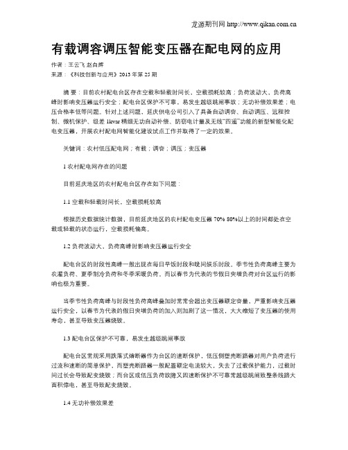
有载调容调压智能变压器在配电网的应用作者:王云飞赵自辉来源:《科技创新与应用》2013年第25期摘要:目前农村配电台区存在空载和轻载时间长,空载损耗较高;负荷波动大,负荷高峰时影响变压器运行安全;配电台区保护不可靠,易发生越级跳闸事故;无功补偿效果差;电压合格率低等问题。
针对上述问题,延庆供电公司引入了具备自动调容、自动调压、远程控制、微机保护、级差1kvar精细无功自动补偿、防窃电计量及无线“四遥”功能的新型智能化配电变压器,开展农村配电网智能化建设试点工作并取得了一定的效果。
关键词:农村低压配电网;有载;调容;调压;变压器1 农村配电网存在的问题目前延庆地区的农村配电台区存在如下问题:1.1 空载和轻载时间长,空载损耗较高根据历史数据统计数据,目前延庆地区的农村配电变压器70%-80%以上的时间都处在空载或轻载的状态运行,空载损耗偏高。
1.2 负荷波动大,负荷高峰时影响变压器运行安全配电台区的时段性高峰一般出现在每日早饭时段和晚间娱乐时段。
季节性负荷高峰主要为农灌负荷、夏季制冷负荷和冬季采暖负荷。
而以春节为代表的节假日突增负荷对台区运行的影响也极为重要。
当季节性负荷高峰与时段性负荷高峰叠加时常常会超出变压器额定容量,严重影响变压器运行安全,以春节为代表的假日突增负荷的加入则加剧了这一情况,大大缩短了变压器的使用寿命,甚至导致变压器烧毁。
1.3 配电台区保护不可靠,易发生越级跳闸事故配电台区常规采用跌落式熔断器作为台区的速断保护,低压侧塑壳断路器对用户负荷进行过流和速断的简单保护,而塑壳断路器一般配置额定电流较大,失去了过载保护能力,过载时间过长会导致配变烧毁;而台区或低压负荷故障又因速断保护不可靠常越级跳闸致整条线路大面积停电,甚至导致配变烧毁。
1.4 无功补偿效果差农网配电台区长期小负荷运行,传统补偿装置电容最低级差10~20kvar不能投入,补偿装置利用率极低。
1.5 电压合格率低配网末端用户距变电站较远,为避免出现电压偏低,设备无法正常运行的情况,兼顾末端负荷,需调高变电站出口电压,这就导致线路首端轻载时电压过高,用电设备寿命缩短,而且配变损耗大幅增加。
自动调容调压变压器参数
ZGS13—Z自动调容调压变压器一、概述ZGS13-Z-型变压器就是根据城、农网建设改造得要求,本着经济、合理、安全、可靠得原则设计得自动调容调压组合式变压器。
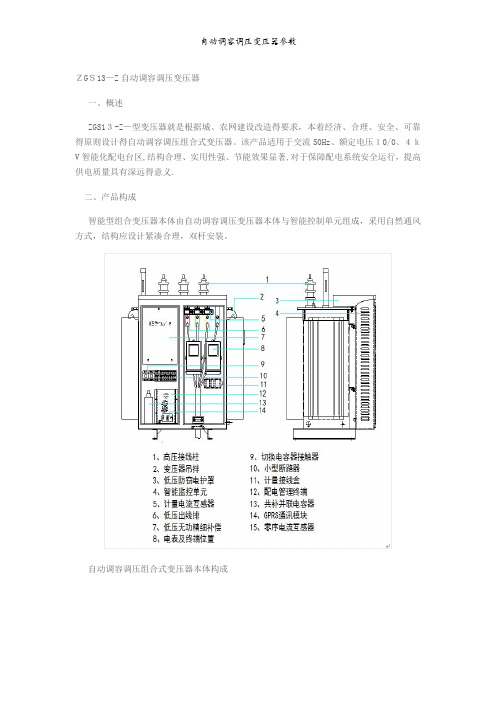
该产品适用于交流50Hz、额定电压10/0、4kV智能化配电台区,结构合理、实用性强、节能效果显著,对于保障配电系统安全运行,提高供电质量具有深远得意义.二、产品构成智能型组合变压器本体由自动调容调压变压器本体与智能控制单元组成,采用自然通风方式,结构应设计紧凑合理,双杆安装。
自动调容调压组合式变压器本体构成变压器控制单元构成三、主要特点1、自动调压功能变压器本体油箱内配置调压开关,在电压波动时自动调节电压高低,使变压器低压侧电压输出稳定在合格范围内,提升供电质量。
调压分接范围为额定电压得±5%。
2、自动调容功能变压器本体油箱内配置调容开关,在用电负荷时段性高峰时自动将变压器调整到大容量档运行,在用电负荷时段性低谷时自动将变压器调整到小容量档运行,有效降低变压器损耗。
3、微机保护方式得过流及短路保护功能线路或负荷出现过流、短路故障,变压器内负控开关自动跳闸并远程上传报警信息,过流与速断保护应采用微机保护方式,保护定值连续可调,便于配合各级保护设备进行定值得精确整定,保证故障线路停电不波及上级开关跳闸。
4、双级漏电保护功能低压配电管理终端具有漏电保护功能,与变压器本体内永磁机构真空开关与配电出线断路器配合,具备进线与出线双级漏电保护功能。
5、就地及远程电动停送电功能变压器本体油箱内配置永磁机构真空开关,可实现就地电动停送电、远程无线遥控停送电功能。
6、无功补偿功能要求变压器智能监控单元内配置低压无功精细补偿隔室,实现级差不大于1kvar得分相分级精细无功自动补偿,采用共分结合优化补偿方式,投切开关采用同步编码开关组,具有投入无涌流,切除无弧光,投切无谐波污染得特点。
7、电能计量功能设置独立密封得计量隔室,密封得主进线直接进入计量隔室,通过母排进入其它隔室,配置一块三相计量接线盒,预留两块三相电子式电表安装位置.电表与计量电流互感器由用方自备.8、GPRS无线“四遥”与配电监测变压器智能监控单元包含支持GPRS无线通讯与配电监测功能得低压配电管理终端,可将监测数据与运行状态实时远传给后台管理系统,支持GPRS方式遥控、遥信、遥调与调测“四遥”功能.四、主要技术参数五、使用环境1)海拔高度:≤2000m2) 环境温度:—25℃ ~ +45℃,24小时内平均温度不超过+35℃;3) 相对湿度:≤90%(25℃)4)抗震能力:地面水平加速度 0、3g,地面垂直加速度 0、15g同时作用持续三个正弦波,安全系数 1、675) 最大风速:≤35m/s6)安装位置:户外7)污秽等级:≤III级;六、外形尺寸图及安装示意图自动调容调压组合式变压器本体外形尺寸图自动调容调压组合式变压器安装示意图。
有载调容变压器说明书
一、适用范围本说明书适用于额定频率为50Hz,电压等级为10kV,三相额定容量为100(30)kVA~630(200)kVA的有载自动调容配电变压器。
二、术语解释S11-M.ZT型有载自动调容配电变压器是一种具有大小两种额定容量,根据用户所带负荷大小由自动调容控制器自动检测判断,并通过特制的有载调容开关,在变压器不停电状态的下,对变压器两种容量进行自动切换,实现对运行过程中变压器容量大小自动调整,从而实现两种额定容量运行方式自动转换的配电变压器。
三、使用场所S11-M.ZT型有载自动调容配电变压器适用于用电季节性强、负荷波动大、用电集中、年平均负载率低的场所。
在我国农村用电主要集中在夏、秋两季,其余季节主要是照明用电,在农忙季节,变压器过载运行现象严重,而在用电淡季,负载率低,又出现了“大马拉小车”的现象,所以载调容配电变压器特别适用于农网改造中;另外,也适用于白天和晚上用电负荷差异较大的住宅小区和常白班的企事业单位。
四、基本原理有载自动调容配电变压器在大容量时,三相高压绕组接成三角形接法(角接),低压绕组并联结构;在小容量时,三相高压绕组接成星形接法(星接),低压绕组串联结构。
高压绕组的星--角转换和低压绕组的串-并联转换,均由有载调容开关来完成,而有载调容开关的切换是由自动控制器根据检测的负载大小情况来决定的。
当变压器由大容量转换为小容量时,由于线圈匝数增加了1.7倍,铁心磁通密度大幅度降低,硅钢片单位损耗变小,空载损耗和空载电流也大幅下降,从而大大降低了变压器的空载无功损耗(小容量时的空载无功损耗小于大容量时损耗的十分之一)和有功损耗(小容量的空载损耗小于大容量损耗的三分之一),达到了节能降耗的目的。
五、变压器本体结构特点1、铁心变压器铁心结构为叠片式结构,采用优质冷轧取向硅钢片,阶梯形三级全斜接缝,不冲孔,改善了磁路结构,增大了接缝面积,减少了接缝处的磁通阻力,与两级接缝相比,空载损耗可降低5%,空载电流可降低20%~30%。
智能调压调容变压器说明书(基本版)
智能型配电变压器——智能化台区最佳方案★自动调压★自动调容★远程可控★远程用电管理安装使用说明书目录1使用场合 (1)2型号说明 (1)3产品组成 (1)4主要功能特点 (2)4.1远程可控 (2)4.2自动调压 (3)4.3自动调容 (4)4.4配合《配电运行管理系统》实时监测和无线“四遥” (4)5技术参数 (5)6附图 (5)6.1外形尺寸图 (5)6.2一次原理图 (6)6.3变压器吊装图 (6)6.4变压器安装方法 (7)7标准配置清单 (8)智能型可控、调压、调容新型变压器1使用场合基本型配电变压器主要用于额定电压10kV、容量315kVA及以下的配电台区,实现远程可控、自动调容、自动调压功能。
2型号说明S11- M·ZT·K-□(□)-10/0.4电压等级(kV)额定容量(小容量)额定容量(大容量)负荷控制自动调压调容密封式损耗水平代号三绕组3产品组成基本型智能配电变压器由变压器本体、智能控制单元两部分组成。
变压器本体内部集成调容开关(低压绕组的串并联,高压接线星三角)、调压开关(高压分接头)、远程可控开关,本体侧面集成的智能控制单元箱内设置低压配电管理终端。
标准型变压器增加兼三相有功不平衡调节的36级精细无功补偿,独特的低压防窃电护罩,计量表位和低压配电计量部件。
注:○10运行指示灯,从左到右依次为:运行状态(运行、报警、分闸、合闸)、调压档位指示(低、中、高)、变压器容量指示(小、大)。
○174芯控制电源插头:二次耐压试验时需拔开并于试验后插好,否则可能损坏智能控制器(变压器低压绕组耐压试验标准高于辅助回路)。
图1:基本型变压器各部分构件图4 主要功能特点 4.1 远程可控⑦①② ③④ ⑧⑤ ⑥○16 ⑨ ○12 ○11 ○14 ○15 ⑩ ○13 ○17 ① 高压接线柱 ② 控制电缆 ③ 智能控制单元 ④ 合闸指示灯 ⑤ 低压接线柱 ⑥ 线圈吊装环⑦ 变压器吊拌⑧ 变压器本体 ⑨ 低压配电管理终端 ⑩ 运行指示灯⑪ 分合闸按钮 ⑫ 通讯天线⑬ GPRS 通讯模块⑭ 信号线⑮ 通讯SIM 卡号⑯ 通讯SIM 卡槽 ⑰4芯控制电源插头智能配电变压器内置永磁真空开关,可实现无线远程停送电,解决了配电台区配电自动化控制的问题。
调压器说明书
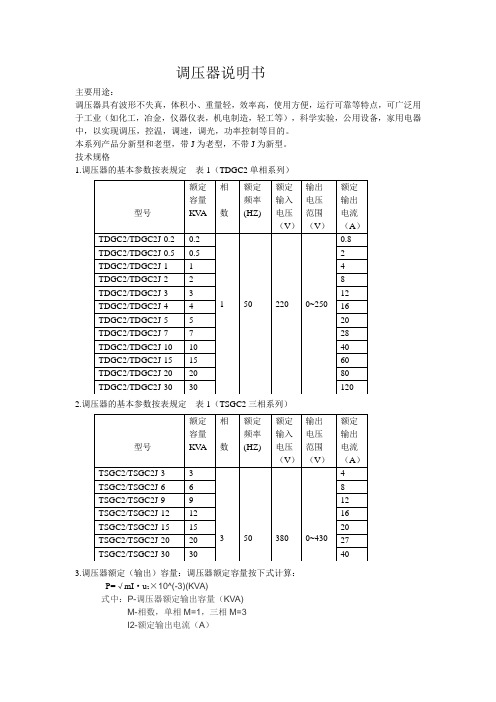
调压器说明书主要用途:调压器具有波形不失真,体积小、重量轻,效率高,使用方便,运行可靠等特点,可广泛用于工业(如化工,冶金,仪器仪表,机电制造,轻工等),科学实验,公用设备,家用电器中,以实现调压,控温,调速,调光,功率控制等目的。
本系列产品分新型和老型,带J为老型,不带J为新型。
技术规格1.调压器的基本参数按表规定表1(TDGC2单相系列)2.调压器的基本参数按表规定表1(TSGC2三相系列)3.调压器额定(输出)容量:调压器额定容量按下式计算:P=√mI·u2×10^(-3)(KVA)式中:P-调压器额定输出容量(KVA)M-相数,单相M=1,三相M=3I2-额定输出电流(A)U2-最大输出电流(V)(三相为线电压)过载(%)不超过(分钟)20 6040 3060 64、调压器绝缘等级为A级,线圈平均温升限值为60℃5、过负荷能力,调压器允许短时间超过额定输出电流值。
但不能超过表2的规定基本原理与主要结构1.基本原理:调压器电刷借助于手轮主轴和刷架的作用,言线圈的磨光表面滑动,变化电刷接触位置、改变一次和二次线圈匝数比,以达到调压的目的。
2、主要结构:①单位结构:单相0.2KV A~10KV A调压器为调压单元结构,一个上端面具有一定宽度的磨光表面的线圈固定在工程塑料的底座上,接触组的电刷在弹簧压力下与线圈的磨光表面金梅接触,转动手轮带动电刷在线圈磨光表面上滑动进行调压。
单元调压器一般为台式,外面有防护通风罩。
单元调压器绕组联接如图一所示:注:图中U1-输入电压(伏)U2-输出电压(伏)D-电刷②单相组装结构,单相大容量调压器是由几个相同规格的单元组装而成,各单元的电刷接触组装在同一主轴上,线圈输入端并联连接平衡电抗器,以平衡单元间电流分布并抑制环流。
单相大容量调压器绕组联接如图2.图3所示:U1-输入电压U2-输出电压D-电刷DK DK1 DK2是平衡电抗器③三相组装结构:三相调压器由三个相同规格的单元同轴组装而成。
调容调压变压器说明书

目录Contents概述技术数据变压器原理及结构主要功能外形尺寸及安装示意订货须知运输、验收和保管安装、维护和检修随机文件1 1 3 6 913 14 15 12自动调容调压变压器1、概述ZGS11-Z型自动调容调压组合变压器(以下简称变压器)是根据城、农网建设改造的要求,研制开发的一种智能化节能型新型设备。
它可根据用户实际运行电压高低、负荷大小、电能质量优劣等实际情况,利用组合式调压调容开关改变变压器线圈各抽头的接法和负荷开关状态,使变压器在不同分接头、额定容量间自动切换,实现自动调容/调压、远程负控、三相有功不平衡调节等功能,还可利用分级精细自动控制进行无功补偿,从而降低空载损耗,实现变压器的节能运行,达到节能目的。
该产品适用于交流50Hz、额定电压10/0.4kV、容量500kVA及以下的配电台区,主要应用于季节性或昼夜负荷变化幅度较大的城市居民区、商业区、工业区和农村电网。
具备智能化操控、结构合理、实用性强、节能效果显著等特点,对于保障配电系统安全运行,提高电网供电质量具有深远的意义。
2、技术数据2.1 型号的表达方式ZG S 11 - Z - □(□)·/ 10 I设计序号电压等级(kV)额定容量(kVA)终端型性能水平代号三相组合共箱式注:□(□)现有额定容量组合方式为500(160)、315(100)、200(63)12.2正常工作条件2.2.1变压器可以在以下温度和湿度环境下正常工作:最高温度+45℃最低温度-25℃(严寒地区-30℃)平均温度24小时内平均温度不超过+35℃日平均相对湿度不大于95%月平均相对湿度不大于90%2.2.2最大风速不超过35m/s(相当于风压小于700Pa)2.2.3空气污秽程度不大于Ⅲ级2.2.4安装场所海拔高度≤2000米2.2.5抗震能力地面水平加速度0.3g,垂直加速度0.15g,同时作用持续三个正弦波,安全系数1.672.2.6户外安装,但不适用于火灾、爆炸、化学腐蚀及剧烈震动场所。
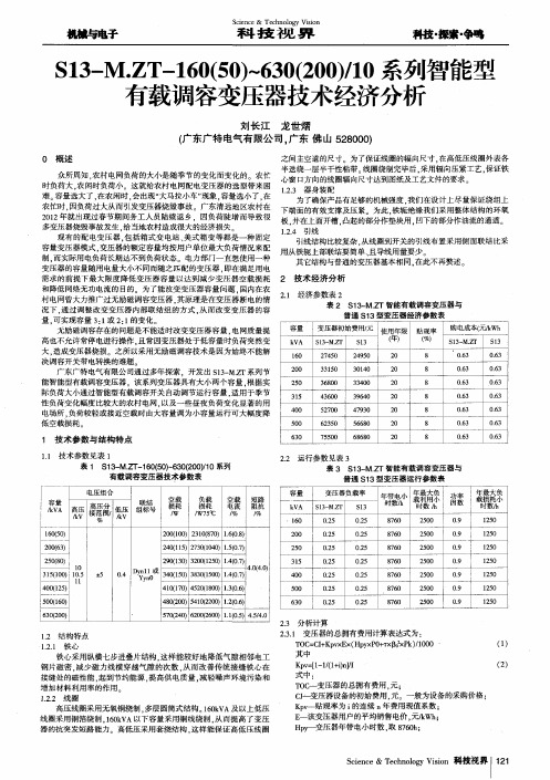
S13-M.ZT-160(50)~630(200)/10系列智能型有载调容变压器技术经济分析
6 3 0
7 5 5 0 . 6 3
O . 6 3
2 . 2 运行参数见表 3 表3 S 1 3 一 M. Z T智能有载调容变压器与 普通 S 1 3型变压 器运行参数表
容量 变压器负载率
S 1 3 - MZ T
机械与电子
S c 科 i e n c e & 技 T e c h 视 n o l o g y 界 V i s i o n
科技
・
探索・ 争鸣
S 1 3 一 M. Z T 一 1 6 0 ( 5 0 ) ~ 6 3 0 ( 2 0 0 ) / 1 0系歹 I J 智能型 有载调容变压器技术经济分析
O . 2 5 0 . 2 5 0 - 2 5 O . 2 5 O . 2 5 O . 2 5 O . 2 5
负载 损耗 / W7 5 ℃
空载 短路 电流 阻抗 , % , %
k V A
1 6 0
S 1 3
刘 长江 龙世 熠 ( 广 东广 特 电气 有 限公 司 , 广东 佛山 5 2 8 0 0 0 )
之 间主空道 的尺寸。为了保证 线圈的辐 向尺 寸 , 在高低压线圈外表各 半迭绕一层半干性粘带。 线圈绕制完毕后 , 采 用辐 向压紧工艺 , 保证铁 众所 周知 , 农村 电网负荷 的大小是 随季 节的变化而变化的 农忙 心窗 口方 向的线圈辐向尺寸达到图纸及工艺文件 的要求 。 时负荷大 . 农 闲时负荷 小。这 就给农村 电网配电变压器的选型带来 困 1 . 2 . 3 器身装配 难。 容量选大 了, 在农 闲时 , 会出现 “ 大马拉小 车” 现象 , 容量选小 了. 在 为 了确保产品有足够的机械强度 . 我们在设计 上尽 量保证 绕组上 农 忙时 . 因负荷 过大从 而引发变压器烧毁事故 广 东清远地区农村在 下端面 的有效支撑及压紧。为此 , 铁轭绝缘 我们采 用整 体结构的环氧 2 0 1 2年就出现过春节期间务工人员 陆续 返乡 .因负荷陡增 而导致很 板. 并在上面开槽 . 凸起 的部分作 垫块用 . 凹下的部分作油流的通道。 多变压器烧毁事故发生 . 给 当地农村造成很大的经济损失 1 . 2 . 4 引线 现有 的配电变压器 , 包括箱式 变电站 、 美式箱 变等都是一种 固定 引线结构比较 复杂 . 从线 圈到开关的引线布置采用侧 面联结 比采 容量变压器模式 . 变压器的额定容量均按用户单位最大 负荷情 况来配 用从铁轭上部联结 要简单 、 且导线用量要少。 制. 而实 际用 电负荷长期达不到负荷状态 电力部 门一直 想使用 一种 其它结构与普 通的变压器基本相 同. 在此不再赘述 。 变压器的容量随用 电量大小不同而随之匹配的变压器 . 即在满 足用电 需求 的前 提下最大 限度 降低变压器 容量以达到减 少变压器空载损耗 2 技术经济分析 和降低 网络无功 电流的 目的。为 了能改变变压器容量 问题 . 国内在农 2 . 1 经济参数表 2 村 电网曾大力推广过无励磁调容变压器 . 其原理是在变压器 断电的情 表2 S 1 3 一 M. Z T智能有载调容变压器与 况下 . 通 过调整改变变压器 内部联结组 的方式 . 从 而改变变压器 的容 普通 ¥ 1 3型变压器经济 参数表 量, 可实现容量 3 : 1 或2 : 1 的变化 。 容量 变压器初始费用, 元 使用年 限 贴 现率 购 电成本f 元 wh 无励磁调容存在的问题是不能适 时改变变压器容量 . 电网质量提 k V A S 1 3 - M . Z T S 1 3 f 年1 ( %) S 1 3M . Z T S 1 3 高也不允许常停电进行操作 . 且常因变压器处于低容量 时负荷 突然变 大. 造成变压器烧损 之所以采用无 励磁调容技术是 因为始终不 能解 1 6 O 2 7 4 5 0 2 4 9 5 0 2 0 8 0 . 6 3 O . 6 3 决调容开关带电转换的难题 2 0 o 3 3 1 5 0 3 0 1 4 ( 】 2 0 8 O . 6 3 O . 6 3 广东广特电气有限公司通 过多年探 索 . 开发 出 S 1 3 一 M . Z T系列节 2 5 0 3 6 8 0 0 3 3 4 0 0 2 0 8 0 . 6 3 O . 6 3 能智能型有载调容变压 器。该 系列变 压器具 有大小两个容量 . 根据实 际负荷大小通过智能型有载调 容开关 自动调节运行容量 . 适用 于季节 3 1 5 4 3 6 0 0 3 9 6 4 O 2 0 8 O . 6 3 O . 6 3 性负荷变化幅度 比较大的农村 电网. 以及 一些昼夜负荷变化显著 的用 4 0 0 5 2 7 0 0 4 7 9 3 0 2 0 8 O . 6 3 O 6 3 电场所 . 负荷较轻或接近空载时由大容量 调为小容量运行可大 幅度 降 5 0 0 6 2 3 5 0 5 6 6 8 0 2 0 8 O . 6 3 O 6 3 低空载损 耗
S11-M-ZT型智能有载调容变压器知识讲解
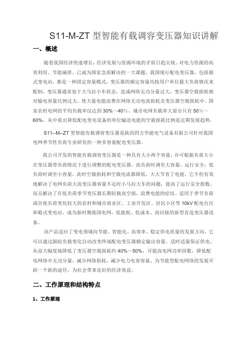
S11-M-ZT型智能有载调容变压器知识讲解一、概述随着我国经济快速增长,经济发展与资源环境的矛盾日趋尖锐。
对电力资源的高效利用、节能减排、已成为国家急需解决的一大课题。
我国现行配电变压器,包括箱式变电站,都是一种固定容量模式,变压器的额定容量均按用户单位最大负荷情况来配制,变压器通常处于大马拉小车状态,造成网络无功分量过大,变压器空载损耗相对输电容量比例过大,使大量电能浪费在网络无功电流损耗及变压器空载损耗中。
国家农村电网的平均负载率仅达到30%~40%,城市电网负载率大部分只有50%~60%,从中看出降低配电变电设备的单位输送电能的空载损耗比例是近期发展趋势,S11--M--ZT型智能有载调容变压器是陕西四方华能电气设备有限公司针对我国电网季节性负荷专业研发的一种多容量配电变压器。
我公司开发的智能有载调容变压器是一种具有大小两个容量,并可根据负荷大小在变压器带负荷情况下进行调整的配电变压器。
高负荷时调至大容量,运行安全;低负荷时调至小容量,此时空载损耗和空载电流都降低,大大节省了电能。
它不但有效地解决了电网负荷大而变压器容量不足时小马拉大车的问题,提高了运行安全指数,而且解决了在低负荷季节变压器长期轻载高空损,浪费电能的症结。
适用于季节负荷或昼夜负荷变化较大的农村和城市商业区、工业开发区、居民小区等10kV配电台区和箱式变电站,成为新时期我国电网,低能耗、低成本、高回报的新型首选变压器设备。
该产品适应了变电领域向节能、智能化、高效率、稳定供电质量的发展方向,它可以通过跟踪负载变化自动改变终端配电变压器额定输出容量,适时适量保证供电,从而大幅度地降低了变压器空载损耗约40%~50%,可提高电网功率因数,降低配电网络中无功分量,减少网络损耗,减少电力电容容量,为节能型配电网络的发展开辟一个新的途径,为社会带来良好的经济效益。
二、工作原理和结构特点1、工作原理智能调容变压器主要是利用安装在变压器外壳上的调容分接开关。
- 1、下载文档前请自行甄别文档内容的完整性,平台不提供额外的编辑、内容补充、找答案等附加服务。
- 2、"仅部分预览"的文档,不可在线预览部分如存在完整性等问题,可反馈申请退款(可完整预览的文档不适用该条件!)。
- 3、如文档侵犯您的权益,请联系客服反馈,我们会尽快为您处理(人工客服工作时间:9:00-18:30)。
智能型配电变压器
——智能化台区最佳方案★自动调压★自动调容
★远程可控★远程用电管理
安装使用说明书
目录
1使用场合 (1)
2型号说明 (1)
3产品组成 (1)
4主要功能特点 (2)
4.1远程可控 (2)
4.2自动调压 (3)
4.3自动调容 (4)
4.4配合《配电运行管理系统》实时监测和无线“四遥” (4)
5技术参数 (5)
6附图 (5)
6.1外形尺寸图 (5)
6.2一次原理图 (6)
6.3变压器吊装图 (6)
6.4变压器安装方法 (7)
7标准配置清单 (8)
智能型可控、调压、调容新型变压器
1使用场合
基本型配电变压器主要用于额
定电压10kV、容量315kVA及以下的
配电台区,实现远程可控、自动调容、
自动调压功能。
2型号说明
S11- M·ZT·K-□(□)-10/0.4
电压等级(kV)
额定容量(小容量)
额定容量(大容量)
负荷控制
自动调压调容
密封式
损耗水平代号
三绕组
3产品组成
基本型智能配电变压器由变压器本体、智能控制单元两部分组成。
变压器本体内部集成调容开关、调压开关、远程可控开关,本体侧面集成的智能控制单元箱内设置低压配电管理终端。
标准型变压器增加兼三相有功不平衡调节的36级精细无功补偿,独特的低压防窃电护罩,计量表位和低压配电计量部件。
1
2
注:○10运行指示灯,从左到右依次为:运行状态(运行、报警、分闸、合闸)、调压档位指示(低、中、高)、变压器容量指示(小、大)。
○
174芯控制电源插头:二次耐压试验时需拔开并于试验后插好,否则可能损坏智能控制器(变压器低压绕组耐压试验标准高于辅助回路)。
图1:基本型变压器各部分构件图
4 主要功能特点 4.1 远程可控
智能配电变压器内置永磁真空开关,可实现无线远程停送电,
⑦
①
② ③
④ ⑧
⑤ ⑥
○16 ⑨ ○12 ○11 ○14 ○15 ⑩ ○13 ○
17 ① 高压接线柱 ② 控制电缆 ③ 智能控制单元 ④ 合闸指示灯 ⑤ 低压接线柱 ⑥ 线圈吊装环
⑦ 变压器吊拌
⑧ 变压器本体 ⑨ 低压配电管理终端 ⑩ 运行指示灯 ⑪ 分合闸按钮 ⑫ 通讯天线
⑬ GPRS 通讯模块
⑭ 信号线
⑮ 通讯SIM 卡号
⑯ 通讯SIM 卡槽 ⑰
4芯控制电源插头
解决了配电台区配电自动化控制的问题。
4.2自动调压
具有自动调压功能,因用户或线路负荷不稳定引起电压波动时,变压器可以自动调节电压高低,提升供电质量,提高设备出力,延长设备寿命,解决了配电网负荷峰谷时段电压合格率低的问题。
传统调压开关是由电机旋转通过传动机构缓慢调节(动作时间一般需要十几秒),而且体积大,价格高,使用复杂,一般应用在1 10kV或35kV主变,难以使用在10kV配电台区。
新型调压开关是通过永磁真空开关和专用转换开关组合实现快速调压。
这种方式具有体积小、转换速度快(小于100ms)、转换过程中无弧光的优点,是配电台区理想的自动调压装置。
低电压的危害:
(1)烧毁电动机。
电压过低超过10%,将使电动机电流增大,线圈温度升高严重时甚至烧损电动机。
(2)增大线损。
在输送一定电力时,电压降低,电流相应增大,引线损增大。
(3)降低送、变电设备能力。
由于电压降低,相应降低线路输送极限容量,因而降低了稳定性,电压过低可能发生电压崩溃事故。
电压过高的危害:
(1)对配变本身的影响
电压过高引起铁芯磁通密度增加,严重时铁芯饱和(尤其是质量差的配变),配变损耗急剧增加,引起谐振,产生谐波,影响其它
3
用电设备。
(2)对用电设备的影响
电压过高会导致大部分的用电设备寿命大幅缩短,并造成损耗增加。
如电压升高10%,白炽灯的使用寿命寿命减少约70%。
4.3自动调容
据资料统计,我国变压器的总损耗约占系统发电量的10%;占电网总损耗60~65%的中、低压电网损耗中,约有70%损耗在配电变压器上。
如果变压器损耗能降低1%,每年就可节约上百亿度电。
在季节性用电高峰和时段性负荷低谷期,配变负荷率很低,往往达不到30%,长时间处于“大马拉小车”状态,造成变压器空载损耗严重。
自动调容变压器,能够根据负荷大小自动调节容量,使变压器在负荷低谷期自动运行在小容量档,轻载时其空载损耗大大降低,小容量空载有功损耗小于大容量时的1/3,节能效果显著。
以200kVA台区为例,与S9型传统配变相比,智能型配变年节能约6000千瓦时。
4.4配合《配电运行管理系统》实时监测和无线“四遥”
无线“四遥”:支持电动操作,并可通过后台软件遥控停送电、查看装置运行数据,查看和修改定值。
远程售电:配置远程管理终端,通过GPRS无线网络,可实现远程预付费用电管理功能,远程售电。
4
5
5 技术参数
6 附图
6.1 外形尺寸图
图1:基本型变压器外形尺寸图
6.2一次原理图
图2:基本型变压器原理图
6.3变压器吊装图
6.3.1变压器吊装方法
正确的变压
器吊装位置
注:请根据产品重量,选择合适的安装工具。
图3:基本型配电变压器吊装图6
6.4变压器安装方法
图4:基本型变压器安装图
7
7标准配置清单
8。