595D336X-025D2T中文资料
明基M22数码摄像机使用说明书
4.1 拍摄影像片段.......................................................30 4.2 从影像片段中拍照...............................................32 4.3 从播放影像片段中撷取图片...............................33 4.4 录音播放摸式.......................................................34 4.5 播放影片/录音.....................................................35 4.6 拍摄/查看照片.....................................................38
有关中国 "电子信息产品污染控制管理办法 " 之相关规定请参考信息产业部所公布之信息
表中标示有 "X"的所有部件都符合 欧盟 RoHS 法规 (欧盟关于电子电器设备中限制使用某些有害物质的 2002/95/EC号指令 )
2.产品环保使用期限的使用条件:
在按照本产品的使用条件使用的情况下 (说明书中对温湿度等使用条件有详细说明),从生产日期开始, 在标志的年限内使用,本产品中含有的有毒有害物质或元素不会对环境造成严重污染或对人身、财产造 成严重损害。
目录
前言 ................................................................................8 关于本手册 .......................................................................8 版权 ................................................................................8 免责声明 ...........................................................................8 安全警告和注意事项 .......................................................8
AD595
介绍了基于单片机的移动式温度数据采集仪的硬件设计,串行红外接口的应用及用可视化编程工具VB6.0实现的WINDOWS界面的数据接收、处理软件。
关键词热电耦温度测量数据采集红外串口通信在电子工业中,随着整机集成度的提高和元器件的微型化、复杂化,在印制板上焊接元件时对各种焊接设备波峰焊、回流焊、SMT 等内的温度工艺要求越来越高。
这就需要一种可移动的温度数据采集仪器,能随传送带进入焊炉内,测量记录下不同焊点印制板上的焊盘孔、过孔等在焊炉内不同位置时的温度参数,并能将测量数据方便地传送给电脑,进行数据曲线的显示、分析和打印,以便制定和执行合适的工艺流程。
无线通信可以去除设备对线缆和连接器的依赖。
IrDA红外通信是一种低价且适应性广的短距离无线通信技术,只要通信双方都支持IrDA 协议,就能很快建立通信链路,实现数据交换。
近来红外通信在电子设备中得到了广泛的应用。
为此,研制了带有红外接口的移动式温度数据采集仪。
该仪器由可充电电池供电,以1Hz的采集率同时对≤8的温度测量点采集600s的数据。
温度测量范围为0℃~300℃,测量精度为满量程的1%。
测量数据存于E2PROM中,可掉电保存,直到下次采集将数据更新。
通过串行红外接口,仪器可将存储的测量数据方便地传送给电脑。
用可视化编程工具Visual Basic6.0制作了Windows界面的数据接收和处理软件,既方便硬件间的连接又便于测量数据的输出与分析。
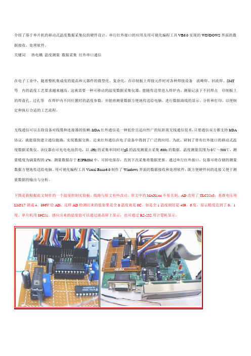
下图是我根据此文制作的一个温度控制实验板。
线路与原文有些改动。
原文中的MAX144不易买到。
AD改用了TLC2543,基准电压用LM317调成4。
096V给AD,这样AD检测出来的值如果是全0温度就是0C。
如是全1温度刚好是409。
6度。
显示精度达到了0。
1度。
单片机用89C51。
感应出来的温度值可以通过液晶屏上显示,也可通过RS-232用计算机显示。
1 采集仪的硬件原理仪器的硬件设计贯彻了确保性能、缩小外形(特别是高度要求苛刻)、便于移动、降低功耗和机内隔热的原则。
WideRlus温度控制仪使用说明书
Wide Rlus 智能数字控制仪使用说明书(香港上润精密仪器有限公司)WP系列显示控制仪使用于各种温度、压力、液位、速度、长度、流量等的测量控制。
采用微处理器进行数学运算,可对各种非线性信号进行高精度的线性矫正。
光柱显示控制仪集数字测量显示和模拟显示于一体采用数码LED显示,可精确的显示控制实时测量值;同时采用高精度101线光柱显示,清晰直观的显示实时测量值(类似模拟表显示)。
可切换输入多种分度号。
采用先进的无跳线技术,更改输入分度号时,不用更改跳线或开关。
整个仪表改型过程不需要断电。
支持多机通讯,可选择多种通讯接口方式,通讯波特率仪表内部参数自由设定。
一、主要技术参数:输入信号:模拟量热电偶:标准热电偶—B、S、K、E、J、T、WRe等电阻:标准热电阻—Pt100、Cu50、或远传压力电阻等电流:0~10mA、4~20mA、0~20mA等—输入电阻≤250电压:0~5V、1~5V、mV等——输入阻抗≥250K测量范围:- 1999~9999字测量精度:0.2%FS±1字或0.5%FS±1字分辨率:1、0.1、0.01或0.001字温度补偿:0~50℃显示方式:-1999~9999测量值显示。
-1999~9999设定值显示0~100%测量值光柱显示。
发光二极管工作状态显示光柱精度:光柱显示精度为1%控制方式:位式ON/ OFF带回差输出信号:模拟量输出:DC0~10mA(负载电阻≤750)DC4~20mA(负载电阻≤500)DC0~5V(输出电阻≤250)DC1~5V(输出电阻≤250)开关量输出:继电器控制输出—继电器ON/OFF带回差。
触电容量:AC220V/3A;DC24/6A(阻性负载)可控硅控制输出—SCR(可控硅过零触发脉冲)输出,可触发可控硅:400V/100A固态继电器输出—SSR(固态继电器控制信号)输出,5~24V/30mA通讯输出:接口方式—标准串行通讯接口:RS-485,RS-232C,RS-422等波特率—300~9600bps 内部自由设定馈电输出:DC24V,负载≤30mA控制或报警方式:可选择2~4限控制或报警,LED指示。
CD595
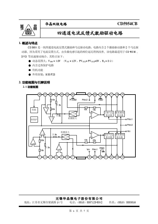
-50 0 50
3.6 4.0
13.5 15.5 17.5
0
1
2
待机工作电流 待机工作电压 待机关断电压
IST VSTON VSTOFF
0.5
0
0.5
2.0
单位
mA
mA V A/V
V
mA V mA mA mV V dB
mV V dB dB
mA V V
第3页共7页
华晶双极电路
4. 测试线路
CD5954CB
相位 (deg)
第5页共7页
华晶双极电路
6. 应用线路与应用说明
6. 1 应用线路
DSP
CD5954CB
u- COM
进给 聚焦 循迹 偏压 待机 主轴
100pF
28 27 26 25 24 23 22
10k
待机 热保护
7.5k 20k
7.5k
2 检测放大
7.5k
检测放大 2
20k
7.5k 10k
1234567
8 4
2
1
0
-1
-2
-3
-4
-5
-2 -1 0
1
2
输入电压 V IN (V)
进给驱动器前级运放频率特性
10k
60
+
180
-
20k
40
90
g
100
Vin
20
0
0
Vcc=12V, -20 PVcc1=
PVcc2=5V
10k
ห้องสมุดไป่ตู้
100k
1M
频率 f (Hz)
-90 -180 10M
W92S11D22D-24D中文资料
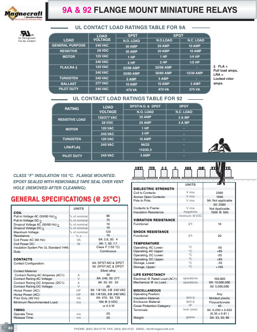
FIG. E
62 84
1
0
62 84 62
1
0
FIG. C
FIG. F
9/04
1...42
IMPROVED FLANGE COVER WITH DIN
MEETS UL 873, UL 508 AND UL 1950 - (0.125 MM) THRU AIR, (0.25 MM) OVER SURFACE
86 W 350 W 7,255 W
PHONE: (843) 393-5778 FAX: (843) 393-4123 EMAIL: info@
% of nominal
Pull-in Voltage DC:<
% of nominal
Dropout Voltage AC (50/60 Hz):>
% of nominal
Dropout Voltage DC:>
% of nominal
Maximum Voltage:
% of nominal
Resistance:
FLA/LRA
TUNGSTEN BALLAST PILOT DUTY
LOAD VOLTAGE
240 VAC 28 VDC 125 VAC
240 VAC 120 VAC 240 VAC 240 VAC 277 VAC 240 VAC
SPST N.O. LOAD
30 AMP 30 AMP
1 HP 2 HP 22/98 AMP 30/80 AMP 5 AMP 10 AMP 470 VA
Weight:
grams
9/04
1...40
PHONE: (843) 393-5778 FAX: (843) 393-4123 EMAIL: info@
74HC595D中文资料_数据手册_参数
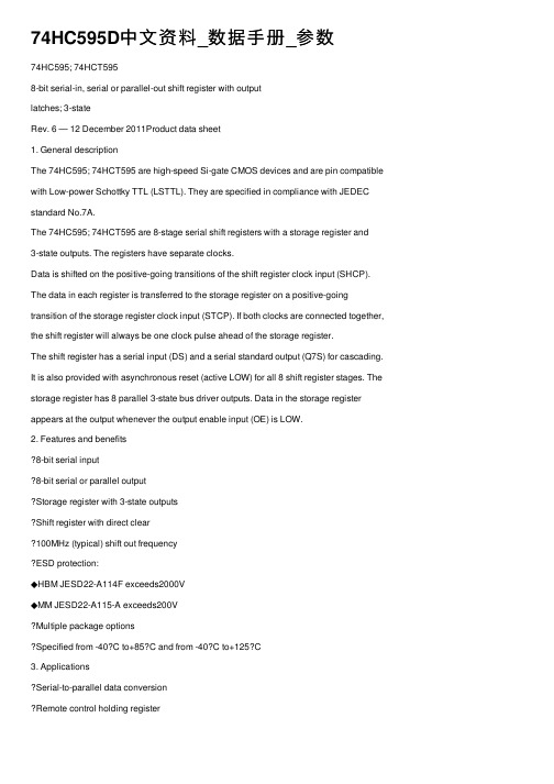
74HC595D中⽂资料_数据⼿册_参数74HC595; 74HCT5958-bit serial-in, serial or parallel-out shift register with outputlatches; 3-stateRev. 6 — 12 December 2011Product data sheet1. General descriptionThe 74HC595; 74HCT595 are high-speed Si-gate CMOS devices and are pin compatible with Low-power Schottky TTL (LSTTL). They are specified in compliance with JEDEC standard No.7A.The 74HC595; 74HCT595 are 8-stage serial shift registers with a storage register and3-state outputs. The registers have separate clocks.Data is shifted on the positive-going transitions of the shift register clock input (SHCP). The data in each register is transferred to the storage register on a positive-going transition of the storage register clock input (STCP). If both clocks are connected together, the shift register will always be one clock pulse ahead of the storage register.The shift register has a serial input (DS) and a serial standard output (Q7S) for cascading. It is also provided with asynchronous reset (active LOW) for all 8 shift register stages. The storage register has 8 parallel 3-state bus driver outputs. Data in the storage register appears at the output whenever the output enable input (OE) is LOW.2. Features and benefits8-bit serial input8-bit serial or parallel outputStorage register with 3-state outputsShift register with direct clear100MHz (typical) shift out frequencyESD protection:◆HBM JESD22-A114F exceeds2000V◆MM JESD22-A115-A exceeds200VMultiple package optionsSpecified from -40C to+85C and from -40C to+125C3. ApplicationsSerial-to-parallel data conversionRemote control holding register3-state4. Ordering information5. Functional diagramTable 1.Ordering informationType numberPackageTemperature rangeName DescriptionVersion 74HC595N -40?C to +125?CDIP16plastic dual in-line package; 16leads (300mil)SOT38-474HCT595N 74HC595D -40?C to +125?CSO16plastic small outline package; 16leads;body width 3.9mmSOT109-174HCT595D 74HC595DB -40?C to +125?CSSOP16plastic shrink small outline package; 16leads; body width 5.3mmSOT338-174HCT595DB 74HC595PW -40?C to +125?CTSSOP16plastic thin shrink small outline package; 16leads; body width 4.4mmSOT403-174HCT595PW 74HC595BQ -40?C to +125?CDHVQFN16plastic dual in-line compatible thermal enhanced very thin quad flat package; no leads; 16terminals; body 2.5 ? 3.5 ? 0.85 mmSOT763-174HCT595BQ3-state3-state 6. Pinning information3-state6.2Pin descriptionTable 2.Pin description Symbol Pin DescriptionQ11parallel data output 1Q22parallel data output 2Q33parallel data output 3Q44parallel data output 4Q55parallel data output 5Q66parallel data output 6Q77parallel data output 7 GND8ground (0 V)Q7S9serial data outputMR10master reset (active LOW)OE13output enable input (active LOW)DS14serial data inputQ015parallel data output 0V CC16supply voltage7. Functional descriptionTable 3.Function table[1]Control Input Output FunctionSHCP STCP OE MR DS Q7S QnX X L L X L NC a LOW-level on MR only affects the shift registersX↑L L X L L empty shift register loaded into storage registerX X H L X L Z shift register clear; parallel outputs in high-impedance OFF-state↑X L H H Q6S NC logic HIGH-level shifted into shift register stage 0. Contents of all shift register stages shifted through, e.g. previous state of stage 6(internal Q6S) appears on the serial output (Q7S).X↑L H X NC QnS contents of shift register stages (internal QnS) are transferred to the storage register and parallel output stages↑↑L H X Q6S QnS contents of shift register shifted through; previous contents of the shift register is transferred to the storage register and the paralleloutput stages[1]H=HIGH voltage state;L=LOW voltage state;↑=LOW-to-HIGH transition;X=don’t care;NC=no change;Z=high-impedance OFF-state.3-state8. Limiting valuesTable 4.Limiting valuesIn accordance with the Absolute Maximum Rating System (IEC 60134). Voltages are referenced to GND (ground = 0 V). Symbol Parameter Conditions Min Max UnitV CC supply voltage-0.5+7VI IK input clamping current V I < -0.5V or V I>V CC+0.5 V-±20mAI OK output clamping current V O<-0.5V or V O > V CC + 0.5 V-±20mAI O output current V O=-0.5V to (V CC+0.5V)pin Q7S-±25mApins Qn-±35mAI CC supply current-70mAI GND ground current-70-mAT stg storage temperature-65+150?CP tot total power dissipationDIP16 package[1]-750mWSO16 package[2]-500mWSSOP16 package[3]-500mWTSSOP16 package[3]-500mWDHVQFN16 package[4]-500mW[1]For DIP16 package: P tot derates linearly with 12mW/K above 70 ?C.[2]For SO16 package: P tot derates linearly with 8mW/K above 70 ?C.[3]For SSOP16 and TSSOP16 packages: P tot derates linearly with 5.5mW/K above 60 ?C.9. Recommended operating conditions10. Static characteristicsTable 5.Recommended operating conditionsSymbol ParameterConditions74HC59574HCT595UnitMinTyp Max Min Typ Max V CC supply voltage 2.0 5.0 6.0 4.5 5.0 5.5V V I input voltage 0-V CC 0-V CC V V O output voltage 0-V CC 0-V CC V ?t/?Vinput transition rise and fall rateV CC = 2.0 V --625---ns/V V CC = 4.5 V - 1.67139- 1.67139ns/V V CC = 6.0 V--83---ns/V T ambambient temperature-40+25+125-40+25+125C Table 6.Static characteristicsAt recommended operating conditions; voltages are referenced to GND (ground =0V).Symbol ParameterConditions-40?C to +85?C -40?C to +125?C UnitMinTypMaxMinMax74HC595V IHHIGH-level input voltageV CC =2.0V 1.5 1.2- 1.5-V V CC =4.5V 3.15 2.4- 3.15-V V CC =6.0VV CC =2.0V -0.80.5-0.5V V CC =4.5V - 2.1 1.35- 1.35V V CC =6.0V- 2.81.8- 1.8VV OHHIGH-level output voltageV I =V IH or V IL all outputsI O =-20µA; V CC =2.0V 1.9 2.0- 1.9-V I O =-20µA; V CC =4.5V 4.4 4.5- 4.4-V I O =-20µA; V CC =6.0V 5.96.0- 5.9-VQ7S outputI O =-4mA; V CC =4.5V 3.84 4.32- 3.7-V I O =-5.2mA; V CC =6.0V 5.345.81- 5.2-VQn bus driver outputs I O =-6mA; V CC =4.5V 3.84 4.32- 3.7-V I O =-7.8mA; V CC =6.0V5.345.81- 5.2-V3-stateV OL LOW-leveloutput voltage V I=V IH or V ILall outputsI O=20µA; V CC=2.0V-00.1-0.1V I O=20µA; V CC=4.5V-00.1-0.1V I O=20µA; V CC=6.0V-00.1-0.1V Q7S output I O=4mA;V CC=4.5V-0.150.33-0.4V I O=5.2mA;V CC=6.0V-0.160.33-0.4V Qn bus driver outputsI O=6mA;V CC=4.5V-0.150.33-0.4V I O=7.8mA;V CC=6.0V-0.160.33-0.4VI I input leakagecurrentV I=V CC or GND; V CC=6.0V--±1.0-±1.0µAI OZ OFF-state--80-160µAC I inputcapacitance- 3.5---pF 74HCT595V IH HIGH-levelinput voltageV CC=4.5V to 5.5V 2.0 1.6- 2.0-VV IL LOW-levelinput voltageV CC=4.5V to 5.5V- 1.20.8-0.8VV OH HIGH-leveloutput voltage V I=V IH or V IL; V CC=4.5Vall outputsI O=-20µA 4.4 4.5- 4.4-V Q7S outputI O=-4mA 3.84 4.32- 3.7-V Qn bus driver outputsI O=-6mA 3.7 4.32- 3.7-VV OL LOW-leveloutput voltage V I=V IH or V IL; V CC=4.5Vall outputsI O=20µA-00.1-0.1V Q7S outputI O=4.0mA-0.150.33-0.4V Qn bus driver outputsI O=6.0mA-0.160.33-0.4VI I input leakagecurrent V I=V CC or GND; V CC=5.5V--±1.0-±1.0µATable 6.Static characteristics …continuedAt recommended operating conditions; voltages are referenced to GND (ground=0V). Symbol Parameter Conditions-40?C to +85?C-40?C to +125?C UnitMin Typ Max Min Max3-stateI OZ OFF-state--80-160µAI CC additionalsupply current per input pin; I O=0A; V I=V CC-2.1V; other inputs at V CC or GND;V CC=4.5V to5.5Vpins MR, SHCP, STCP, OE-150675-735µA pin DS-25113-123µAC I inputcapacitance - 3.5---pFTable 6.Static characteristics …continuedAt recommended operating conditions; voltages are referenced to GND (ground=0V).Symbol Parameter Conditions-40?C to +85?C-40?C to +125?C UnitMin Typ Max Min Max3-state 11. Dynamic characteristicsTable 7.Dynamic characteristicsVoltages are referenced to GND (ground = 0 V); for test circuit see Figure14.Symbol Parameter Conditions25 ?C-40?C to+85 ?C-40?C to+125 ?C UnitMin Typ[1]Max Min Max Min Max74HC595t pd propagationdelay SHCP to Q7S; see Figure9[2]V CC = 2 V-52160-200-240ns V CC = 4.5 V-1932-40-48ns V CC = 6 V-1527-34-41ns STCP to Qn; see Figure10[2] V CC = 2 V-55175-220-265ns V CC = 4.5 V-2035-44-53ns V CC = 6 V-1630-37-45ns MR to Q7S; see Figure12[3] V CC = 2 V-47175-220-265ns V CC = 4.5 V-1735-44-53ns V CC = 6 V-1430-37-45nst en enable time OE to Qn; see Figure13[4]V CC = 2 V-47150-190-225nsV CC = 4.5 V-1730-38-45nsV CC = 6 V-1426-33-38ns t dis disable time OE to Qn; see Figure13[5]V CC = 2 V-41150-190-225nsV CC = 4.5 V-1530-38-45nsV CC = 6 V-1227-33-38ns t W pulse width SHCP HIGH or LOW;V CC = 4.5 V156-19-22-nsV CC = 6 V135-16-19-nsSTCP HIGH or LOW;see Figure10V CC = 2 V7511-95-110-nsV CC = 4.5 V154-19-22-nsV CC = 6 V133-16-19-nsMR LOW; see Figure12V CC = 2 V7517-95-110-nsV CC = 4.5 V156-19-22-nsV CC = 6 V135-16-19-ns3-statet suset-up timeDS to SHCP; see Figure 10V CC = 2 V 5011-65-75-ns V CC = 4.5 V 104-13-15-ns V CC = 6 V 9 3-11-13-nsSHCP to STCP; see Figure 11V CC = 2 V 7522-95-110-ns V CC = 4.5 V 158-19-22-ns V CC = 6 V 137-16-19-ns t hhold timeDS to SHCP; see Figure 11V CC = 2 V 3-6-3-3-ns V CC = 4.5 V 3-2-3-3-ns V CC = 6 V3-2-3-3-ns t recrecovery timeMR to SHCP; see Figure 12V CC = 2 V 50-19-65-75-ns V CC = 4.5 V 10-7-13-15-ns V CC = 6 V 9-6-11-13f maxmaximum frequencySHCP or STCP; see Figure 9 and 10V CC = 2 V 930- 4.8-4-MHz V CC = 4.5 V 3091-24-20-MHz V CC = 6 V35108-28-24-MHz C PDpower dissipation capacitancef i = 1 MHz; V I =GND to V CC [6][7]-115-----pF74HCT595; V CC = 4.5 V to 5.5 V t pdpropagation delay SHCP to Q7S; see Figure 9[2]-2542-53-63ns STCP to Qn; see Figure 10[2]-2440-50-60ns MR to Q7S; see Figure 12[3]-2340-50-60ns t en enable time OE to Qn; see Figure 13[4]-2135-44-53ns t dis disable time OE to Qn; see Figure 13[5] -1830-38-45ns t Wpulse widthSHCP HIGH or LOW;see Figure 9166-20-24-ns STCP HIGH or LOW; see Figure 10165-20-24-ns MR LOW; see Figure 12208-25-30-ns t suset-up timeDS to SHCP; see Figure 10165-20-24-ns SHCP to STCP; see Figure 11168-20-24-ns t hhold timeDS to SHCP; see Figure 113-2-3-nsTable 7.Dynamic characteristics …continuedVoltages are referenced to GND (ground = 0 V); for test circuit see Figure 14.Symbol Parameter Conditions25 ?C -40?C to +85 ?C -40?C to +125 ?C Unit Min Typ [1]Max Min Max Min Max3-state[1]Typical values are measured at nominal supply voltage.[2]t pd is the same as t PHL and t PLH .[3]t pd is the same as t PHL only.[4]t en is the same as t PZL and t PZH .[5]t dis is the same as t PLZ and t PHZ .[6]C PD is used to determine the dynamic power dissipation (P D in µW).P D =C PD ?V CC 2?f i +∑(C L ?V CC 2?f o )where:f i=input frequency in MHz;f o =output frequency in MHz;∑(C L ?V CC 2?f o )=sum of outputs;C L =output load capacitance in pF;V CC =supply voltage in V.[7]All 9outputs switching.12. Waveformst rec recovery time MR to SHCP; see Figure 1210-7-13-15-ns f max maximum frequencySHCP and STCP; see Figure 9 and 103052-24-20-MHz C PDpower dissipation capacitancef i = 1 MHz; V I =GND to V CC [6] [7]-130-----pFTable 7.Dynamic characteristics …continuedVoltages are referenced to GND (ground = 0 V); for test circuit see Figure 14.Symbol Parameter Conditions25 ?C -40?C to +85 ?C -40?C to +125 ?C Unit Min Typ [1]Max Min Max Min Max3-stateTable 8.Measurement points Type Input OutputV M V M74HC5950.5V CC0.5V CC 74HCT595 1.3V 1.3V3-stateTable 9.Test data74HC595V CC6ns50 pF1kΩopen GND V CC74HCT5953V6ns50 pF1kΩopen GND V CC3-state 13. Package outlineDIP16: plastic dual in-line package; 16 leads (300 mil)SOT38-4Fig 15.Package outline SOT38-4 (DIP16)3-state SO16: plastic small outline package; 16 leads; body width 3.9 mm SOT109-1Fig 16.Package outline SOT109-1 (SO16)3-state SSOP16: plastic shrink small outline package; 16 leads; body width 5.3 mm SOT338-1Fig 17.Package outline SOT338-1 (SSOP16)3-state TSSOP16: plastic thin shrink small outline package; 16 leads; body width 4.4 mm SOT403-1Fig 18.Package outline SOT403-1 (TSSOP16)。
CAT336D 336DL 样本中文

336D/®336D L液压挖掘机2336D/336D L 液压挖掘机D 系列采用了创新技术,提高了性能和多功能性。
Cat ® 代理商会与您签订《客户服务协议》并据此提供各种售后服务。
代理商可帮助您选定计划,以解决从机器配置到最终更换等维修和保养延长的维修周期、先进的过滤技术、便于更换的滤清器和用户友好型电子诊断系统使得维修快速便捷,从而提高了生产率,并节约了保养成本。
第 12 页操作台提供宽大的空间、更佳的视野,且开关触手可及。
监控器是一个彩色图形显示屏,使操作员易于掌握机器信息。
总之,新型驾驶室为操作员提供了一个舒适的工作环境。
第 6 页✔液压系统液压系统的设计使这款机器具有优异的可靠性和操控性。
选装的机具控制系统提高了灵活性。
第 5 页发动机采用 ACERT™ 技术的 C9 发动机油耗更低,磨损更少。
它针对燃烧环节进行改进,以优化发动机性能,并降低排放。
通过将 ACERT 技术与新型省油模式和功率管理相结合,客户可兼顾性能和燃油经济性需求,以适应自身的需要和应用。
第 4 页✔✔ 新特性3作业机具 - 附件“卡特彼勒作业机具” 可提供铲斗、连接器、液压锤和液压剪等多种作业机具。
第 10 页✔动臂和斗杆可配备三种长度的动臂和八种斗杆,以适应各种应用条件。
第 9 页结构Caterpillar ® 的设计和制造技术可确保这些重要零部件坚固耐用,且使用寿命长。
第 8 页卡特彼勒 C9。
采用 ACERT™ 技术的卡特彼勒 C9 发动机引入了一系列循序渐进的改进,在发动机技术方面取得突破性进展。
ACERT 技术主要包括燃油输送、空气管理以及电子控制。
ACERT 技术优化了发动机性能,同时还符合各种非公路用发动机的当地排放法规。
通过将 ACERT 技术与新型经济模式相结合,客户可兼顾性能和燃油经济性需求,以适应自身的需要和应用。
性能。
336D/336D L 配置了采用 ACERT 技术的 C9 发动机,与 330C/330C L 中的 C9 发动机相比,其功率提高了 9%。
AD9235中文资料
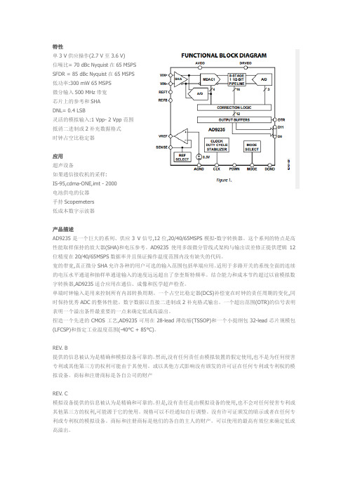
特性单3 V供应操作(2.7 V至3.6 V)信噪比= 70 dBc Nyquist在65MSPSSFDR = 85 dBc Nyquist在65MSPS低功率:300 mW 65MSPS微分输入500 MHz带宽芯片上的参考和SHADNL= 0.4 LSB灵活的模拟输入:1 Vpp- 2 Vpp范围抵消二进制或2补充数据格式时钟占空比稳定器应用超声设备如果通信接收机的采样:IS-95,cdma-ONE,imt - 2000电池供电的仪器手持Scopemeters低成本数字示波器产品描述AD9235是一个巨大的系列、供应3 V信号,12位,20/40/65MSPS模拟-数字转换器。
这个系列的特点是高性能取样保持的放大器(SHA)和电压参考。
AD9235使用多级微分管线式架构与输出误差修正提供逻辑12位精度在20/40/65MSPS数据率并且保证操作温度范围内没有缺失的代码。
宽的带宽,真正微分SHA允许各种的用户可选的输入范围包括单端应用。
适用于多路开关的系统全面的连续的电压水平通道和抽样单通道输入的速度远远超出了奈奎斯特频率。
结合能力和成本节约超过以前模拟数字转换器,AD9235适合应用在通信、成像和医学超声检查。
单端时钟输入是用来控制所有内部转换周期。
一个占空比稳定器(DCS)补偿宽在时钟的责任周期的变化,同时保持优秀ADC的整体性能。
数字数据以直接二进制或2补充格式输出。
一个超出范围(OTR)的信号表明表明一个溢出条件最重要的一点来确定低或高溢出。
捏造一个先进的CMOS工艺,AD9235可用在28-lead薄收缩(TSSOP)和一个小提纲包32-lead芯片规模包(LFCSP)和指定工业温度范围(-40°C + 85°C)。
REV. B提供的信息被认为是精确和模拟设备可靠的。
然而,没有任何责任由模拟装置的假定使用,也不是为任何侵害专利或其他第三方的权利可能由于其使用。
或以其他方式影响没有颁发的许可证在任何专利或专利权的模拟设备。
福禄克说明书
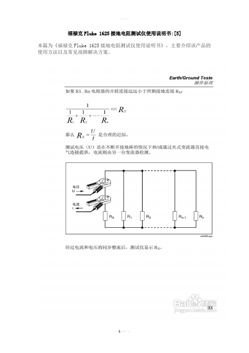
福禄克Fluke 1625接地电阻测试仪使用说明书:[5]本篇为《福禄克Fluke 1625接地电阻测试仪使用说明书》,主要介绍该产品的使用方法以及常见故障解决方案。
100 Ω精度±(读数的 2 % + 2 位数)操作误差±(读数的 5 % + 5 位数)测量时间通常为 6 秒最大干扰电压24 V,超过 24 V 无法启动测量最大过载U rms最大= 250 V电阻测量(R 直流)测量方法可按照 IEC61557-4 进行电流-电压测量测量电压20 V 直流电短路电流250 mA 直流电测量值的公式对于四极测量,可延长 H、S、ES 导线而不会产生附加误差。
导线 E 中的电阻 > 1 Ω时,可导致 5m Ω/Ω的附加误差。
测量范围0.020 Ω至 300 kΩ显示范围0.001 Ω至 2.999 Ω3.00 Ω至 29.99 Ω30.0 Ω至 299.9 Ω300 Ω至 2999 Ω3.0 kΩ至 29.99 kΩ30.0 kΩ至 299.9 kΩ分辨率0.001 Ω0.01 Ω0.1 Ω1 Ω10 Ω100 Ω精度±(读数的 2 % + 2 位数)操作误差±(读数的 5 % + 5 位数)测量序列约 2 次测量/秒测量时间通常为 4 秒,包括极性反转(二极或四极)最大干扰电压直流或交流电压≤3 V,超过 3 V 无法启动测量最大感应率 2 Henry最大过载U rms = 250 V导线电阻补偿 (R K)在 R [414]K在 R [416]E在 R [418]E在 R [420]测量值的公式R 显示屏 = R 测得 - R 补偿** 设定点输入值 RK = 0.000 Ω,通过调整测量在 0.000 至 29.99 Ω范围内变化。
无桩接地回路测量(双钳口,无桩)开关档位RA 四极(双钳口,无桩)分辨率0.001 Ω至 0.1 Ω测量范围0.02 Ω至 199.9 Ω精度±(读数的 7 % + 3 位数)操作误差±(读数的 10 % + 5 位数)测量电压Vm = 48 V 交流(初级电压)测量频率128 Hz噪声电流 (IEXT) 最大IEXT = 10 A(交流)(RA < 20 Ω)最大IEXT = 2 A(交流)(RA > 20 Ω)测量原理:使用两个电流互感器对闭合环路中的电阻进行无桩测量。
W25X16中文手册
W25X16,W25X32,W25X64
描封
脚类IC 态0时m除l
PDIP 总00m除l
PAD封N类
PAD封NAM状
1
/CS
I
2
DO
O
3
/WP
I
4
GND
5
DIO
I/O
6
CLK
I
7
/HOLD
I
8
VCC
擦封脚类IC 总00m除l
W脚类N 描×指MM
I/类
F芯NCTI类N
/
时封脚类IC 总00m除l
9Fh
ID
ID
DO
DIO CLK
个
ID ID
ID 8
email:richgood@
17
W25X16\W25X32\W25X64
Cortex-M0
JEDEC ID
ID Manufa部turer an释 Dev除部e I释ent除f除部at除on
ration
PAD封N类 1 2
W25X16,W25X32,W25X64
PAD封NAM状
I/类
/HOLD
I
VCC
email:richgood@
3
F芯NCTI类N
W25X16\W25X32\W25X64
Cortex-M0
3
N/C
4
N/C
5
N/C
6
N/C
7
/CS
I
8
DO
O
9
/WP
I
10
GND
11
N/C
12
N/C
13
N/C
MAX3362中文资料

General DescriptionThe MAX3362 low-power, high-speed transceiver for RS-485/RS-422 communication operates from a single +3.3V power supply. The device contains one differen-tial transceiver consisting of a line driver and receiver.The transceiver operates at data rates up to 20Mbps,with an output skew of less than 6ns. Driver and receiv-er propagation delays are guaranteed below 50ns. This fast switching and low skew make the MAX3362 ideal for multidrop clock/data distribution applications.The output level is guaranteed at +1.5V with a standard 54Ωload, compliant with RS-485 specifications. The transceiver draws 1.7mA supply current when unloaded or fully loaded with the drivers disabled.Additionally, the MAX3362 has a low-power shutdown mode, reducing the supply current to 1µA.The MAX3362 has a 1/8-unit-load receiver input imped-ance, allowing up to 256 transceivers on the bus. The MAX3362 is designed for half-duplex communication.The device has a hot-swap feature that eliminates false transitions on the data cable during circuit initialization.The drivers are short-circuit current limited, and a ther-mal shutdown circuit protects against excessive power dissipation.The MAX3362 is available in an 8-pin SOT package and specified over industrial and automotive tempera-ture ranges.ApplicationsClock/Data Distribution Telecom Equipment Security EquipmentPoint-of-Sale Equipment Industrial ControlsFeatureso Space-Saving 8-Pin SOT Package o Guaranteed 20Mbps Data Rate o Operates from a Single +3.3V Supply o 6ns (max) Transmitter and Receiver Skew o Hot-Swap Featureo Interoperable with +5V Logico Allows up to 256 Transceivers on the Bus o 1µA Low-Power Shutdown Mode o 1.7mA Operating Supply Current o -7V to +12V Common-Mode Range o Current Limiting and Thermal Shutdown o Half-Duplex Operationo Automotive Temperature Range VariantsMAX33623.3V , High-Speed, RS-485/RS-422 Transceiver inSOT Package________________________________________________________________Maxim Integrated Products 1Ordering Information19-2218; Rev 1; 5/02For pricing, delivery, and ordering information,please contact Maxim/Dallas Direct!at 1-888-629-4642, or visit Maxim’s website at .Typical Operating CircuitPin Configuration and Functional Diagram appear at end of data sheet.M A X 33623.3V , High-Speed, RS-485/RS-422 Transceiver in SOT Package 2_______________________________________________________________________________________ABSOLUTE MAXIMUM RATINGSDC ELECTRICAL CHARACTERISTICS(V= +3.3V ±5%, T = T to T , unless otherwise noted. Typical values are at V = +3.3V and T = +25°C.) (Notes 1, 2)Stresses beyond those listed under “Absolute Maximum Ratings” may cause permanent damage to the device. These are stress ratings only, and functional operation of the device at these or any other conditions beyond those indicated in the operational sections of the specifications is not implied. Exposure to absolute maximum rating conditions for extended periods may affect device reliability.All voltages with respect to GND.V CC , RE , DE, DI ......................................................-0.3V to +6V Receiver Input Voltages, Driver OutputVoltages (A, B).......................................................-8V to +13V Receiver Input Current, Driver OutputCurrent (A, B).................................................................250mA |V A - V B |..................................................................................+8V Receiver Output Voltage (RO)....................-0.3V to (V CC + 0.3V)Continuous Power Dissipation (T A = +70°C)8-Pin SOT (derate 9.7mW/°C above +70°C) ...............777mW Operating Temperature RangeMAX3362E__ ..................................................-40°C to +85°C MAX3362A__ ................................................-40°C to +125°C Storage Temperature Range.............................-65°C to +150°C Junction Temperature......................................................+150°C Lead Temperature (soldering, 10s).................................+300°CMAX33623.3V , High-Speed, RS-485/RS-422 Transceiver inSOT PackageDC ELECTRICAL CHARACTERISTICS (continued)(V= +3.3V ±5%, T = T to T , unless otherwise noted. Typical values are at V = +3.3V and T = +25°C.) (Notes 1, 2)SWITCHING CHARACTERISTICS (MAX3362E_ _ only)(V CC = +3.3V ±5%, T A = T MIN to T MAX , unless otherwise noted. Typical values are at V CC = +3.3V and T A = +25°C.) (Note 1)M A X 33623.3V , High-Speed, RS-485/RS-422 Transceiver in SOT Package 4_______________________________________________________________________________________Note 2:All currents into the device are positive; all currents out of the device are negative. All voltages are referenced to deviceground, unless otherwise noted.Note 3:∆V OD and ∆V OC are the changes in V OD and V OC , respectively, when the DI input changes state.Note 4:The short-circuit output current applies to peak current just prior to foldback-current limiting; the short-circuit foldback out-put current applies during current limiting to allow a recovery from bus contention.Note 5:Shutdown is enabled by bringing RE high and DE low. If the enable inputs are in this state for less than 50ns, the device isguaranteed not to enter shutdown. If the enable inputs are in this state for at least 600ns, the device is guaranteed to have entered shutdown.Note 6:Transition time from shutdown mode to normal operation.SWITCHING CHARACTERISTICS (MAX3362E_ _ only)(continued)(V = +3.3V ±5%, T = T to T , unless otherwise noted. Typical values are at V = +3.3V and T = +25°C.) (Note 1)MAX33623.3V , High-Speed, RS-485/RS-422 Transceiver inSOT Package_______________________________________________________________________________________5Typical Operating Characteristics(V CC = +3.3V, T A = +25°C, unless otherwise noted.)010520153530254001.00.51.52.02.53.03.5OUTPUT CURRENT vs. RECEIVER OUTPUTLOW VOLTAGEM A X 3362 t o c 01RECEIVER OUTPUT LOW VOLTAGE (V)O U T P U T C U R R E N T (m A )-30-20-25-10-15-5001.52.00.51.02.53.03.5OUTPUT CURRENT vs. RECEIVER OUTPUTHIGH VOLTAGEM A X 3362 t o c 02RECEIVER OUTPUT HIGH VOLTAGE (V)O U T P U T C U R R E N T (m A )3.223.233.253.243.26-40-1053550-25658095110125RECEIVER OUTPUT HIGH VOLTAGEvs. TEMPERATUREM A X 3362 t o c 03TEMPERATURE (°C)R E C E I V E R O U T P U T H I G H V O L T A G E (V )2000.010.020.030.040.05-40-105-25203550658095110125RECEIVER OUTPUT LOW VOLTAGEvs. TEMPERATUREM A X 3362 t o c 04TEMPERATURE (°C)R E C E I V E R O U T P U T L O W V O L T A G E (V )DRIVER OUTPUT CURRENTvs. DIFFERENTIAL OUTPUT VOLTAGEM A X 3362 t o c 05DIFFERENTIAL OUTPUT VOLTAGE (V)D R I VE R O U T P U T C U R R E N T (m A )3.23.02.82.62.4153045607502.23.4DRIVER DIFFERENTIAL OUTPUT VOLTAGEvs. TEMPERATURETEMPERATURE (°C)D R I VE R D IF F E R E N T I A L O U T P U T V O L T AG E (V )1109580655035205-10-250.51.01.52.02.53.00-40125DRIVER OUTPUT CURRENT vs. DRIVER OUTPUT LOW VOLTAGEM A X 3362 t o c 07DRIVER OUTPUT LOW VOLTAGE (V)D R I VE R O U T P U T C U R R E N T (m A )11108923456711020304050607080901001101201300012DRIVER OUTPUT CURRENT vs. DRIVER OUTPUT HIGH VOLTAGEM A X 3362 t o c 08DRIVER OUTPUT HIGH VOLTAGE (V)D R I VE R O U T P U T C U R R E N T (m A )4312-5-4-3-2-10-6-130-120-110-100-90-80-70-60-50-40-30-20-10010-140-75SUPPLY CURRENT vs. TEMPERATUREM A X 3362t o c 09TEMPERATURE (°C)I C C (m A )11095-25-10535506520801.691.701.711.721.731.741.751.761.68-40125M A X 33623.3V , High-Speed, RS-485/RS-422 Transceiver in SOT Package 6_______________________________________________________________________________________SHUTDOWN SUPPLY CURRENTvs. TEMPERATUREM A X 3362 t o c 10TEMPERATURE (°C)I S H D N (µA )1109580655035205-10-250.20.40.60.81.01.21.40-40125DRIVER OUTPUT SKEW vs. TEMPERATUREM A X 3362 t o c 11TEMPERATURE (°C)D R I VE R O U T P U T S K E W (n s )110956580-105203550-250.020.040.060.080.100.120.140.160.180.200.220.240.260-40125252729313335RECEIVER PROPAGATION DELAYvs. TEMPERATUREM A X 3362 t o c 12R E C E I V E R P R O P AG A T I O N D E L A Y (n s )-40-1053550-25658095110125TEMPERATURE (°C)2020ns/divUNLOADED DRIVER OUTPUTWAVEFORMM A X 3362 t o c 13B3.3Vf DIN = 16MbpsA20ns/divLOADED DRIVER OUTPUTWAVEFORMM A X 3362 t o c 14B2Vf DIN = 16Mbps R L = 54ΩA20ns/divDRIVER PROPAGATION DELAYMAX3362 toc15Af DIN = 16MbpsDIN2V/divB3.3V20ns/divRECEIVER PROPAGATION DELAYMAX3362 toc16ROf DIN = 16MbpsA2V/div2V/divBTypical Operating Characteristics (continued)(V CC = +3.3V, T A = +25°C, unless otherwise noted.)MAX33623.3V , High-Speed, RS-485/RS-422 Transceiver inSOT Package_______________________________________________________________________________________7Figure 2. Driver Timing Test CircuitFigure 3. Driver Propagation DelayFigure 1. Driver DC Test Load Figure 4. Driver Enable and Disable Times (t PDSL , t PDZL , t PDLS ,t PDLZ )M A X 33623.3V , High-Speed, RS-485/RS-422 Transceiver in SOT Package 8_______________________________________________________________________________________Figure 5. Driver Enable and Disable Times (t PDSH , t PDZH , t PDHS , t PDHZ)Figure 6. Receiver Propagation DelaysMAX33623.3V , High-Speed, RS-485/RS-422 Transceiver inSOT Package_______________________________________________________________________________________9Detailed DescriptionThe MAX3362 low-power, high-speed transceiver for RS-485/RS-422 communication operates from a single +3.3V power supply. The device contains one differen-tial line driver and one differential line receiver. The dri-ver and receiver may be independently enabled. When disabled, outputs enter a high-impedance state.The transceiver guarantees data rates up to 20Mbps,with an output skew of less than 6ns. This low skew time makes the MAX3362 ideal for multidrop clock/datadistribution applications, such as cellular base stations.Driver and receiver propagation delays are below 50ns.The output level is guaranteed at 1.5V on a standard 54Ωload.The device has a hot-swap feature that eliminates false transitions on the data cable during circuit initialization.Also, drivers are short-circuit current limited and are protected against excessive power dissipation by ther-mal shutdown circuitry.Figure 7. Receiver Enable and Disable TimesM A X 33623.3V , High-Speed, RS-485/RS-422 Transceiver in SOT Package 10______________________________________________________________________________________The MAX3362 has a 1/8-unit-load receiver input imped-ance, allowing up to 256 transceivers to be connected simultaneously on a bus. The MAX3362 is designed for half-duplex communication.DriverThe driver transfers single-ended input (DI) to differen-tial outputs (A, B). The driver enable (DE) input controls the driver. When DE is high, driver outputs are enabled.These outputs are high impedance when DE is low. When the driver is enabled, setting DI low forces the noninverting output (A) low and inverting output (B)high. Conversely, drive DI high to force noninverting output high and inverting output low (Table 1).Drive RE high and DE low (disable both receiver and driver outputs) to enter low-power shutdown mode.ReceiverThe receiver reads differential inputs from the bus lines (A, B) and transfers this data as a single-ended output (RO). The receiver enable (RE ) input controls the receiver. Drive RE low to enable the receiver. Driving RE high places RO into a high-impedance state. When the receiver is enabled, RO is high if (A-B) ≥200mV. RO is low if (A-B) ≤-200mV.Drive RE high and DE low (disable both receiver and driver outputs) to enter low-power shutdown mode.Hot-Swap CapabilityHot-Swap InputWhen circuit boards are inserted into a hot or powered backplane, disturbances to the enable and differential receiver inputs can lead to data errors. Upon initial cir-cuit board insertion, the processor undergoes its power-up sequence. During this period, the output dri-vers are high impedance and are unable to drive the DE input of the MAX3362 to a defined logic level.Leakage currents up to 10µA from the high-impedance output could cause DE to drift to an incorrect logic state. Additionally, parasitic circuit board capacitance could cause coupling of V CC or GND to DE. These fac-tors could improperly enable the driver.When V CC rises, an internal pulldown circuit holds DE low for at least 10µs and until the current into DE exceeds 200µA. After the initial power-up sequence,the pulldown circuit becomes transparent, resetting the hot-swap tolerable input.Hot-Swap Input CircuitryThe MAX3362 enable inputs feature hot-swap capability.At the input there are two NMOS devices, M1 and M2(Figure 8). When V CC ramps from 0, an internal 10µs timer turns on M2 and sets the SR latch, which also turns on M1. Transistors M2, a 300µA current sink, and M1, a 30µA current sink, pull DE to GND through an 8k Ωresis-tor. M2 is designed to pull DE to the disabled state against an external parasitic capacitance up to 100pF that may drive DE high. After 10µs, the timer deactivates M2 while M1 remains on, holding DE low against three-state leakages that may drive DE high. M1 remains on until an external source overcomes the required input current. At this time, the SR latch resets and M1 turns off.When M1 turns off, DE reverts to a standard, high-impedance CMOS input. Whenever V CC drops below 1V, the hot-swap input is reset.For RE there is a complimentary circuit employing two PMOS devices pulling RE to V CC .Hot-Swap Line TransientThe circuit of Figure 9 shows a typical offset termination used to guarantee a greater than 200mV offset when a line is not driven (the 50pF represents the minimum parasitic capacitance that would exist in a typical appli-cation). During a hot-swap event when the driver isMAX33623.3V , High-Speed, RS-485/RS-422 Transceiver inSOT Package______________________________________________________________________________________11Figure 8. Simplified Structure of the Driver Enable Input (DE)Figure 9. Differential Power-Up Glitch (Hot Swap)10µs/divFigure 10. Differential Power-Up Glitch (0.1V/µs)M A X 33623.3V , High-Speed, RS-485/RS-422 Transceiver in SOT Package 12______________________________________________________________________________________connected to the line and is powered up the driver must not cause the differential signal to drop below 200mV. Figures 10, 11, and 12 show the results of the MAX3362 during power-up for three different V CC ramp rates (0.1V/µs, 1V/µs, and 10V/µs). The photos show the V CC ramp, the single-ended signal on each side of the 100Ωtermination, as well as the differential signal across the termination.Low-Power Shutdown ModeLow-power shutdown mode is initiated by bringing both RE high and DE low. I n shutdown, the MAX3362 typi-cally draws only 1µA supply current.RE and DE may be driven simultaneously; the device is guaranteed not to enter shutdown if RE is high and DE is low for less than 50ns. If the inputs are in this state for at least 600ns, the device will enter shutdown.Enable times t PDZH, t PDZL, t PRZH and t PRZL in the Switching Characteristics table assume the device was not in a low-power shutdown state. Enable times t PDSH,t PDSL, t PRSH,and t PRSL assume the device was shut down. Drivers and receivers take longer to become enabled from low-power shutdown mode than from driver/receiver disable mode.Applications InformationPropagation DelaysFigures 5 and 6 show the typical propagation delays.Skew time is simply the difference between the low-to-high and high-to-low propagation delay. Small driver/receiver skew times help maintain a symmetrical mark-space ratio (50% duty cycle). Both the receiver skew time and driver skew time are under 6ns.256 Transceivers on the BusThe standard RS-485 receiver input impedance is 12k Ω(one-unit load), and a standard driver can drive up to 32 unit loads. The MAX3362 transceiver has a 1/8-unit-load receiver input impedance (96k Ω), allowing up to 256 transceivers to be connected in parallel on one communication line. Any combination of these devices and/or other RS-485 transceivers with a total of 32 unit loads or less can be connected to the line.Driver Output ProtectionTwo mechanisms prevent excessive output current and power dissipation caused by faults or by bus con-tention. The first, a foldback current limit on the output stage, provides immediate protection against short cir-cuits over the whole common-mode voltage range (see Typical Operating Characteristics ). The second, a ther-mal shutdown circuit, forces the driver outputs into a high-impedance state if the die temperature becomes excessive.Typical ApplicationsThe MAX3362 transceiver is designed for bidirectional data communications on multipoint bus transmission lines. The Typical Operating Circuit shows a typical net-work applications circuit. To minimize reflections, the line should be terminated at both ends in its character-istic impedance, and stub lengths off the main line should be kept as short as possible.1µs/divFigure 11. Differential Power-Up Glitch (1V/µs)200ns/divFigure 12. Differential Power-Up Glitch (10V/µs)MAX33623.3V , High-Speed, RS-485/RS-422 Transceiver inSOT Package______________________________________________________________________________________13Pin ConfigurationFunctional DiagramChip InformationTRANSISTOR COUNT: 708PROCESS: BiCMOSM A X 33623.3V , High-Speed, RS-485/RS-422 Transceiver in SOT Package Maxim cannot assume responsibility for use of any circuitry other than circuitry entirely embodied in a Maxim product. No circuit patent licenses are implied. Maxim reserves the right to change the circuitry and specifications without notice at any time.14____________________Maxim Integrated Products, 120 San Gabriel Drive, Sunnyvale, CA 94086 408-737-7600©2002 Maxim Integrated ProductsPrinted USAis a registered trademark of Maxim Integrated Products.Package Information(The package drawing(s) in this data sheet may not reflect the most current specifications. For the latest package outline information,go to /packages .)。
MJD350 300V PNP高电压传输器TO252(DPAK)商品说明书
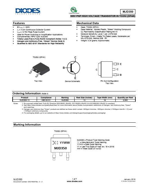
Features∙ BV CEO > -300V∙ I C = -0.5A Continuous Collector Current ∙ I CM = -0.75A Peak Pulse Current∙ Ideal for Power Switching or Amplification Applications ∙ Complementary NPN Type: MJD340∙ Totally Lead-Free & Fully RoHS Compliant (Notes 1 & 2) ∙ Halogen and Antimony Free. “Green” Device (Note 3) ∙ Qualified to AEC-Q101 Standards for High ReliabilityMechanical Data∙ Case: TO252 (DPAK)∙ Case Material: Molded Plastic, "Green" Molding Compound UL Flammability Classification Rating 94V-0 ∙ Moisture Sensitivity: Level 1 per J-STD-020∙ Terminals: Finish – Matte Tin Plated Leads, Solderable per MIL-STD-202, Method 208 ∙Weight: 0.34 grams (Approximate)Ordering Information (Note 4)Notes: 1. No purposely added lead. Fully EU Directive 2002/95/EC (RoHS), 2011/65/EU (RoHS 2) & 2015/863/EU (RoHS 3) compliant.2. See https:///quality/lead-free/ for more information about Diodes Incorporated’s definitions of Hal ogen- and Antimony-free, "Green" and Lead-free.3. Halogen and Antimony free "Green” products are defined as those which contain <900ppm bromine, <900ppm chlorine (<1500ppm tot al Br + Cl) and <1000ppm antimony compounds.4. For packaging details, go to our website at https:///design/support/packaging/diodes-packaging/.Marking InformationTop ViewDevice SchematicPin Out ConfigurationTop ViewMJD350 = Product Type Marking Code = Manufacturers’ Code Marking YYWW = Date Code MarkingYY = Last Two Digits of Year (ex: 18 = 2018) WW = Week Code (01 to 53)TO252 (DPAK)TO252 (DPAK)MJD350Thermal Characteristics(@T A = +25°C, unless otherwise specified.)Notes: 5. For a device mounted on FR-4 PCB with minimum recommended pad layout.6. Refer to JEDEC specification JESD22-A114 and JESD22-A115.Thermal Characteristics and Derating InformationElectrical Characteristics(@T A = +25°C, unless otherwise specified.)Note: 7. Measured under pulsed conditions. Pulse width ≤300μs. Duty cycle ≤2%.Typical Electrical Characteristics(@T A = +25°C, unless otherwise specified.)Package Outline DimensionsPlease see /package-outlines.html for the latest version.TO252 (DPAK)Suggested Pad LayoutPlease see /package-outlines.html for the latest version.TO252 (DPAK)Note:For high voltage applications, the appropriate industry sector guidelines should be considered with regards to creepage and clearance distances between device Terminals and PCB tracking.7°±1°Seating Plane。
平面锉齿式金属圆锯片[实用新型专利]
![平面锉齿式金属圆锯片[实用新型专利]](https://img.taocdn.com/s3/m/28596988b84ae45c3a358c33.png)
专利名称:平面锉齿式金属圆锯片专利类型:实用新型专利
发明人:陈唯明
申请号:CN200420026659.6申请日:20040422
公开号:CN2706266Y
公开日:
20050629
专利内容由知识产权出版社提供
摘要:本实用新型涉及一种平面锉齿式金属圆锯片,广泛使用于切割金属材料、花岗岩、大理石、瓷砖、耐火材料及水泥制品等,属于切割工具技术领域。
其主要采用在锯片基体上制成内平面、外圈凸缘平面,外圈凸缘平面高于内平面,其特征是在外圈凸缘平面的正反面上制成锉刀齿,在基体外圆圆周上制成圆周齿。
本实用新型结构简单,合理;由于采用渗金属表面改性新技术及强韧化热处理新工艺制成的锯片,并在上面制成锉刀齿及圆周齿,其耐热、耐蚀、耐磨;由于在金相显示锯片表层覆有渗入金属的金属碳化物,能提高基体硬度及表面硬度,基体硬度>HRC64,表面硬度>
HV2500;能提高使用性能,并能延长其使用寿命。
申请人:陈唯明
地址:214031 江苏省无锡市锡山新村18号702室
国籍:CN
代理机构:无锡市大为专利事务所
代理人:殷红梅
更多信息请下载全文后查看。
LUCD05FU 产品数据表特性说明书

LUCD05FUProduct datasheetCharacteristicsLUCD05FUAdvanced control unit, TeSys U, 1.25-5A, 3P motors, protection & diagnostic, class 20, coil 110-240V AC/DCMainRange of product TeSys U Range TeSys Product name TeSys U Device short name LUCDProduct or component type Advanced control unit Device application Motor control Motor protectionProduct specific application Basic protection and advanced functions, communication Main function availableManual resetProtection against phase failure and phase imbalance Earth fault protectionProtection against overload and short-circuit Product compatibilityPower base LUB12Power base LUB32Power base LUB38Power base LUB120Power base LUB320Power base LUB380Reversing contactor breaker LU2B12FU Reversing contactor breaker LU2B32FU Reversing contactor breaker LU2B38FU [Ue] rated operational voltage 690 V AC Network frequency 40...60 HzLoad type3-phase motor - cooling: self-cooled Utilisation categoryAC-44AC-41AC-43Motor power kW1.5 kW at 400...440 V AC 50/60 Hz2.2 kW at 500 V AC 50/60 Hz 3 kW at 690 V AC 50/60 Hz Rated motor current adjustment range1.25…5 Ai s c l a i m e r : T h i s d o c u m e n t a t i o n i s n o t i n t e n d e d a s a s u b s t i t u t e f o r a n d i s n o t t o b e u s e d f o r d e t e r m i n i n g s u i t a b i l i t y o r r e l i a b i l i t y o f t h e s e p r o d u c t s f o r s p e c i f i c u s e r a p p l i c a t i o n sThermal overload class Class 20 - frequency limit: 40…60 Hz - temperature compensation: -25…70 °C conforming to IEC60947-6-2Class 20 - frequency limit: 40…60 Hz - temperature compensation: -25…70 °C conforming to UL 508 Tripping threshold14.2 x Ir +/- 20 %Phase failure sensitivity Yes[Uc] control circuit voltage110...240 V AC110...220 V DCComplementaryControl circuit voltage limits88...264 V for AC circuit 110...240 V in operation88...242 V for DC circuit 110...220 V in operation55 V for AC circuit 110...240 V drop-out55 V for DC circuit 110...220 V drop-outTypical current consumption280 mA at 110...240 V AC I maximum while closing with LUB12280 mA at 110...240 V AC I maximum while closing with LUB32280 mA at 110...240 V AC I maximum while closing with LUB38280 mA at 110...220 V DC I maximum while closing with LUB12280 mA at 110...220 V DC I maximum while closing with LUB32280 mA at 110...220 V DC I maximum while closing with LUB3835 mA at 110...240 V AC I rms sealed with LUB1225 mA at 110...240 V AC I rms sealed with LUB3225 mA at 110...240 V AC I rms sealed with LUB3835 mA at 110...220 V DC I rms sealed with LUB1225 mA at 110...220 V DC I rms sealed with LUB3225 mA at 110...220 V DC I rms sealed with LUB38Heat dissipation2 W for control circuit with LUB123 W for control circuit with LUB323 W for control circuit with LUB38Operating time35 ms opening with LUB12 for control circuit35 ms opening with LUB32 for control circuit35 ms opening with LUB38 for control circuit50 ms closing with LUB12 for control circuit50 ms closing with LUB32 for control circuit50 ms closing with LUB38 for control circuitReset Manual resetStandards EN 60947-6-2IEC 60947-6-2UL 60947-4-1, with phase barrierCSA C22.2 No 60947-4-1, with phase barrierProduct certifications CEULCSACCCEACASEFAATEXMarine[Ui] rated insulation voltage690 V conforming to IEC 60947-6-2600 V conforming to UL 60947-4-1600 V conforming to CSA C22.2 No 60947-4-1[Uimp] rated impulse withstand voltage6 kV IEC 60947-6-2Safe separation of circuit400 V SELV between the control and auxiliary circuits conforming to IEC 60947-1400 V SELV between the control or auxiliary circuit and the main circuit conforming to IEC 60947-1 Fixing mode Plug-in (front face)Width45 mmHeight66 mmDepth60 mmCompatibility code LUCDEnvironmentIP degree of protection IP20 front panel and wired terminals conforming to IEC 60947-1IP20 other faces conforming to IEC 60947-1IP40 front panel outside connection zone conforming to IEC 60947-1Protective treatment TH conforming to IEC 60068Ambient air temperature for operation-25…70 °CAmbient air temperature for storage-40…85 °COperating altitude2000 mFire resistance960 °C parts supporting live components conforming to IEC 60695-2-12650 °C conforming to IEC 60695-2-12Shock resistance10 gn power poles open conforming to IEC 60068-2-2715 gn power poles closed conforming to IEC 60068-2-27Vibration resistance 2 gn, 5…300 Hz, power poles open conforming to IEC 60068-2-64 gn, 5…300 Hz, power poles closed conforming to IEC 60068-2-6Resistance to electrostatic discharge8 kV level 3 in open air conforming to IEC 61000-4-28 kV level 4 on contact conforming to IEC 61000-4-2Non-dissipating shock wave1 kV serial mode conforming to IEC 60947-6-22 kV common mode conforming to IEC 60947-6-2Resistance to radiated fields10 V/m 3 conforming to IEC 61000-4-3Resistance to fast transients2 kV class 3 serial link conforming to IEC 61000-4-44 kV class 4 all circuits except for serial link conforming to IEC 61000-4-4Immunity to radioelectric fields10 V conforming to IEC 61000-4-6Immunity to microbreaks3 msImmunity to voltage dips70 % / 500 ms conforming to IEC 61000-4-11Offer SustainabilitySustainable offer status Green Premium productEU RoHS Directive CompliantEU RoHS DeclarationMercury free YesRoHS exemption information YesChina RoHS Regulation China RoHS declarationProduct out of China RoHS scope. Substance declaration for your informationEnvironmental Disclosure Product Environmental ProfileCircularity Profile End of Life InformationWEEE The product must be disposed on European Union markets following specific waste collection andnever end up in rubbish binsContractual warrantyWarranty18 monthsLUCD05FU。
WS336-5.0资料
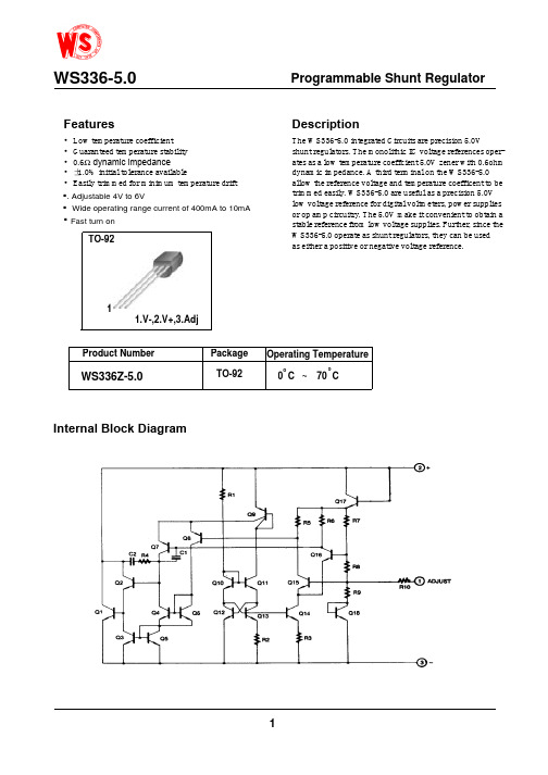
Rev.Features•Low temperature coefficient • Guaranteed temperature stability •0.6Ω dynamic impedance •±1.0% initial tolerance available•Easily trimmed for minimum temperature driftDescriptionThe WS 336-5.0 integrated Circuits are precision 5.0Vshunt regulators. The monolithic IC voltage references oper-ates as a low temperature coeffcient 5.0V zener with 0.6ohm dynamic impedance. A third terminal on the WS 336-5.0 allow the reference voltage and temperature coefficent to be trimmed easily. WS 336-5.0 are useful as a precision 5.0V low voltage reference for digital voltmeters, power supplies or op amp circuitry. The 5.0V make it convenient to obtain a stable reference from low voltage supplies. Further, since the WS 336-5.0 operate as shunt regulators, they can be used as either a positive or negative voltage reference.Internal Block DiagramProgrammable Shunt Regulator1Product Number Operating TemperatureTO-920 C ~70 Coo1.V-,2.V+,3.Adj.Wide operating range current of 400mA to 10mA Fast turn on..WS336Z-5.0Absolute Maximum RatingsElectrical Characteristics(0°C < T A < +70°C , unless otherwise specified)ParameterSymbol Value Unit Reverse Current I R15 mA Forward CurrentI F 10mA Operating Temperature Range KA336-2.5/B T OPR 0 ~ + 70°C Storage Temperature RangeT STG- 60 ~ + 150°CParameter Symbol ConditionsWS 336-5.0Min.Typ.Max.Min.Typ.Max.UnitReverse Breakdown VoltageV R T A = +25°CI R = 1mA 4.85 5.0 5.15VReverse Breakdown Change with Current ∆V R /∆I R T A = +25°C600uA ≤I R ≤ 10mA- 620 m V Reverse Dynamic ImpedanceZ D T A = +25°CI R = 1mA - 0.6 2 ΩTemperature Stability ST TI R = 1mA-4 mVReverse Breakdown Change with Current ∆V R /∆I R 400uA ≤ I R ≤10mA - 6 24 mV Reverse Dynamic Impedance Z D I R = 1mA -0.8ΩLong Term Stability In reference voltageSTI R = 1mA- 20 - ppm/KhrWS336-5.0122.5Typical Perfomance CharacteristicsFigure 1.Reverse Voltage Change Figure 3.Temperature Drift Figure 2.Reverse Characteristics Figure 4.Forward Characteristics WS336-5.0。
221015A02 XL2576 DEMO 板使用说明书

页数:第1 页,共3 页描述221015A02是为产品XL2576制作的演示板,用于DC8V~40V输入,输出电压5V,输出电流3A的降压恒压应用演示,最高转换效率可以达到86%。
XL2576是开关降压型DC-DC转换芯片;固定开关频率52KHz,可减小外部元器件尺寸,方便EMC设计。
芯片具有出色的线性调整率与负载调整率,输出电压支持1.23V~37V间任意调节。
芯片内部集成过流保护、过温保护、短路保护等可靠性模块。
XL2576为标准TO263-5L封装,集成度高,外围器件少,应用灵活。
DEMO原理图引脚介绍页 数:第 2 页, 共 3 页物料清单序号 数量 参考位号 说明生产商型号 生产商 1 2 C1,C2 1uF,50V,Ceramic,X7R,0805 C2012X7R1H105K TDK 2 1 CFF 33nF,50V,Ceramic,X7R,0603 C1608X7R1H333K TDK 3 2 CIN, COUT220uF,50V,Electrolytic,(10*16) YXJ-50V-220uFRubycon 4 1 D1 60V,5A,SMC,Schottky Barrier RectifierB560CDIODES5 1 L1 100uH,4A,(18*9)6 1 R1 14K Ω,1%,1/16W,Thick Film,0603 RC0603FR-0714KL Yageo7 1 R2 43K Ω,1%,1/16W,Thick Film,0603RC0603FR-0743KLYageo 81U140V,3A,BUCK,DC-DC Converter,TO263-5LXL2576XLSEMIDEMO 实物图PCB 布局40mm顶层 底层30mm页数:第3 页,共3 页应用信息输入电容选择在连续模式中,转换器的输入电流是一组占空比约为VOUT/VIN的方波。
为了防止大的瞬态电压,必须采用针对最大RMS电流要求而选择低ESR(等效串联电阻)输入电容器。
双踪示波器介绍V-252
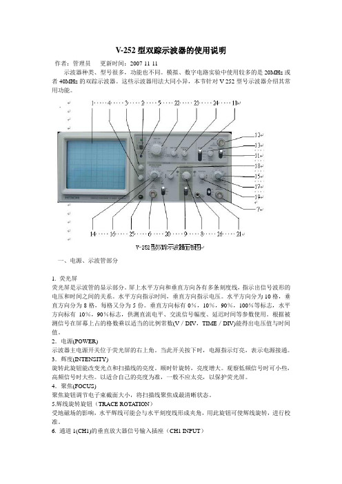
V-252型双踪示波器的使用说明作者:管理员更新时间:2007-11-11示波器种类、型号很多,功能也不同。
模拟、数字电路实验中使用较多的是20MHz或者40MHz的双踪示波器。
这些示波器用法大同小异,本节针对V-252型号示波器介绍其常用功能。
一、电源、示波管部分1. 荧光屏荧光屏是示波管的显示部分。
屏上水平方向和垂直方向各有多条刻度线,指示出信号波形的电压和时间之间的关系。
水平方向指示时间,垂直方向指示电压。
水平方向分为10格,垂直方向分为8格,每格又分为5份。
垂直方向标有0%,10%,90%,100%等标志,水平方向标有10%,90%标志,供测直流电平、交流信号幅度、延迟时间等参数使用。
根据被测信号在屏幕上占的格数乘以适当的比例常数(V/DIV,TIME/DIV)能得出电压值与时间值。
2.电源(POWER)示波器主电源开关位于荧光屏的右上角。
当此开关按下时,电源指示灯亮,表示电源接通。
3.辉度(INTENSITY)旋转此旋钮能改变光点和扫描线的亮度。
顺时针旋转,亮度增大。
观察低频信号时可小些,高频信号时大些。
以适合自己的亮度为准,一般不应太亮,以保护荧光屏。
4.聚焦(FOCUS)聚焦旋钮调节电子束截面大小,将扫描线聚焦成最清晰状态。
5.辉线旋转旋钮(TRACE ROTATION)受地磁场的影响,水平辉线可能会与水平刻度线形成夹角,用此旋钮可使辉线旋转,进行校准。
6. 通道1(CH1)的垂直放大器信号输入插座(CH1 INPUT)通道1垂直放大器信号输入BNC插座。
当示波器工作于X-Y模式时作为X信号的输入端。
7. 通道2(CH2)的垂直放大器信号输入插座(CH2 INPUT)通道2垂直放大器信号输入BNC插座。
当示波器工作于X-Y模式时作为Y信号的输入端。
8.垂直轴工作方式选择开关(MODE)输入通道有五种选择方式:通道1(CH1)、通道2(CH2)、双通道交替显示方式(ALT)、双通道切换显示方式(CHOP).叠加显示方式(ADD)。
595芯片管脚的作用
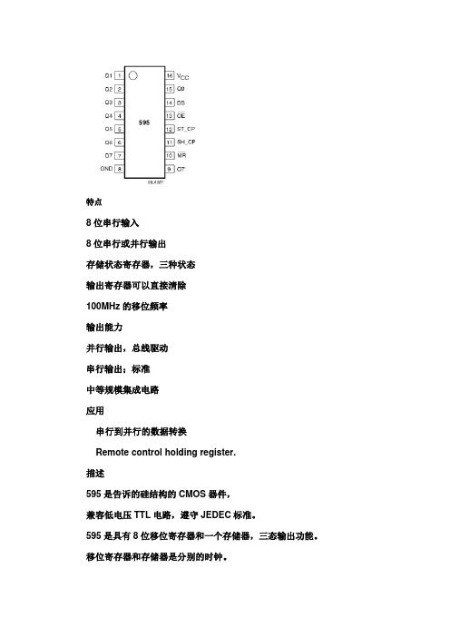
特点8位串行输入8位串行或并行输出存储状态寄存器,三种状态输出寄存器可以直接清除100MHz的移位频率输出能力并行输出,总线驱动串行输出;标准中等规模集成电路应用串行到并行的数据转换Remote control holding register.描述595是告诉的硅结构的CMOS器件,兼容低电压TTL电路,遵守JEDEC标准。
595是具有8位移位寄存器和一个存储器,三态输出功能。
移位寄存器和存储器是分别的时钟。
数据在SCHcp的上升沿输入,在STcp的上升沿进入的存储寄存器中去。
如果两个时钟连在一起,则移位寄存器总是比存储寄存器早一个脉冲。
移位寄存器有一个串行移位输入(Ds),和一个串行输出(Q7’),和一个异步的低电平复位,存储寄存器有一个并行8位的,具备三态的总线输出,当使能OE时(为低电平),存储寄存器的数据输出到总线。
参考数据符号参数条件TYP 单位HC HCttPHL/tPLH 传输延时SHcp到Q7’STcp到QnMR到Q7’CL=15pFVcc=5V161714 212019 NsNsNsfmax STcp到SHcp最大时钟速度10057 MHzCL 输入电容Notes 1 3.5 3.5 pFCPD Power dissipation capacitance per package. Notes2115 130 pFCPD决定动态的能耗,PD=CPD×VCC×f1+∑(CL×VCC2×f0)F1=输入频率,CL=输出电容f0=输出频率(MHz)Vcc=电源电压引脚说明符号引脚描述Q0…Q7 15,1,7 并行数据输出GND 8 地Q7’ 9 串行数据输出MR 10 主复位(低电平)SHCP 11 移位寄存器时钟输入STCP 12 存储寄存器时钟输入OE 13 输出有效(低电平)DS 14 串行数据输入VCC 16 电源功能表输入输出功能SHCP STCP O E MR DS Q7’ Qn× × L ↓ × L NC MR为低电平时紧紧影响移位寄存器× ↑ L L × L L 空移位寄存器到输出寄存器× × H L × L Z 清空移位寄存器,并行输出为高阻状态↑ × L H H Q6’ NC 逻辑高电平移入移位寄存器状态0,包含所有的移位寄存器状态移入,例如,以前的状态6(内部Q6”)出现在串行输出位。
- 1、下载文档前请自行甄别文档内容的完整性,平台不提供额外的编辑、内容补充、找答案等附加服务。
- 2、"仅部分预览"的文档,不可在线预览部分如存在完整性等问题,可反馈申请退款(可完整预览的文档不适用该条件!)。
- 3、如文档侵犯您的权益,请联系客服反馈,我们会尽快为您处理(人工客服工作时间:9:00-18:30)。
For technical questions, contact: tantalum@Document Number: 4000778Revision: 04-Sep-06595DVishay SpragueSolid Tantalum Chip CapacitorsT ANTAMOUNT ®Conformal Coated, Maximum CVFEATURES•Large capacitance rating range •Terminations: Tin (2) standard•8 mm, 12 mm tape and reel packaging available per EIA 481-1 and reeling per IEC 286-3. 7"[178 mm] standard. 13" [330 mm] available.•Case code compatibility with EIA 535BAAC and CECC30801 molded chipsCapacitance Range: 0.1 µF to 1500 µFCapacitance Tolerance: ± 10 %, ± 20 % standard Voltage Rating: 4 WVDC to 50 WVDCPERFORMANCE CHARACTERISTICSOperating Temperature: - 55 °C to + 85 °C (To + 125 °C with voltage derating)Note:Refer to Doc. 40088ORDERING INFORMATION595D 106X0010A2TT YPECAPACITANCE CAPACITANCE T OLERANCE DC VOLTAGE RATINGAT + 85 °C CASE CODE T ERMINATION PACKAGING This is expressed in picofarads. The first two digits are the significant figures. The third is the number of zeros to follow.X0 = ± 20 %X9 = ± 10 %This is expressed in volts. To complete the three-digit block, zeros precede the voltage rating. A decimal point is indicated by an "R" (6R3 = 6.3 volts).See Ratings and Case Codes Table2 = 100 % Tin 4 = Gold Plated 8 = Solder Plated (60/40)Special OrderT = Tape and Reel7" [178 mm] Reel W = 13" [330 mm] Reel See Tape and ReelSpecifications.Note: Preferred Tolerance and reel sizes are in bold.We reserve the right to supply higher voltage ratings and tighter capacitance tolerance capacitors in the same case size. Voltage substitutions will be marked with the higher voltage rating.* Pb containing terminations are not RoHS compliant, exemptions may applyDocument Number: 40007For technical questions, contact: tantalum@Revision: 04-Sep-0679595DSolid Tantalum Chip Capacitors T ANTAMOUNT ® Conformal Coated,Maximum CVVishay SpragueRATINGS AND CASE CODESµF4 V6.3 V10 V16 V20 V25 V35 V50 V 0.10T 0.15T 0.22T 0.33T A 0.47TA A 0.68T A A/B 1.0TA AB 1.5T A A/BC 2.2T T/A A A B B/C 3.3T T A B/C C C 4.7T T A A/B B/C C 6.8T A A/B B C C/D 10T A A/B B B/C D D/R 15A A A/B A/B BC C/D R 22A/B A B/M B/C C/D D/R R33A/B S/A/B A/B B/C C/D R 47A A/B B B/C C/D D/R R68A A/B B/C C/D D D/R 100A/B B/C/M B/D C/D D/R R120C C D R R 150B/C C/D D/R R180D D D/R R 220C/D C/D/G/H C/D/R R 270C/D R 330C*C/D/R D/R R390D R R 470C/R D/R R 560R 680D R R1000R R 1500R* Preliminary values, contact factory for availabilitySTANDARD/EXTENDED RATINGSCAPACITANCE(µF)CASE CODEPART NUMBERMAX. DCL AT + 25 °C (µA)MAX. DF AT + 25 °C 120 Hz (%)MAX. ESR AT + 25 °C 100 kHz (Ohms)MAX. RIPPLE 100 kHz Irms (Amps)4 WVDC AT+ 85 °C, SURGE = 5.2 V . . . 2.7 WVDC AT + 125 °C, SURGE = 3.4 V4.7 T 595D475X_004T2T 0.5 6 7.8 0.06 10 T 595D106X_004T2T 0.5 6 7.8 0.06 15 A 595D156X_004A2T 0.6 6 1.4 0.23 33A595D336X_004A2T 1.3 6 1.4 0.2333 B 595D336X_004B2T 1.3 6 0.47 0.43 47 A 595D476X_004A2T 1.9 6 1.400.2368 A 595D686X_004A2T 2.7 6 1.30 0.24100 A 595D107X_004A2T 4.0 12 0.60 0.35100 B 595D107X_004B2T 4.0 8 0.45 0.44120 C 595D127X_004C2T 4.8 8 0.19 0.76* Preliminary values, contact factory for availability. For 10 % tolerance, specify "9"; for 20 % tolerance, change to "0".595DVishay SpragueSolid Tantalum Chip Capacitors T ANTAMOUNT ® Conformal Coated,Maximum CV For technical questions, contact: tantalum@Document Number: 4000780Revision: 04-Sep-06STANDARD/EXTENDED RATINGSCAPACITANCE(µF)CASE CODEPART NUMBERMAX. DCL AT + 25 °C (µA)MAX. DF AT + 25 °C 120 Hz (%)MAX. ESR AT + 25 °C 100 kHz (Ohms)MAX. RIPPLE 100 kHz Irms (Amps)4 WVDC AT + 85 °C, SURGE = 5.2 V . . . 2.7 WVDC AT + 125 °C, SURGE = 3.4 V150 B 595D157X_004B2T 6.0 8 0.45 0.44 150 C 595D157X_004C2T 6.0 8 0.18 0.78 180 D 595D187X_004D2T 7.2 8 0.14 1.04 220 C 595D227X_004C2T 8.8 8 0.18 0.78 220 D 595D227X_004D2T 8.8 8 0.14 1.04 270 C 595D277X_004C2T 10.8 8 0.17 0.80 270D 595D277X_004D2T 10.880.13 1.07330* C* 595D337X_004C2T* 13.2* 8* 0.17*0.80* 390 D 595D397X_004D2T 15.680.13 1.07470 C 595D477X_004C2T 18.8 10 0.16 0.83 470 R 595D477X_004R2T 18.8 10 0.13 1.39 680 D 595D687X_004D2T 27.2 12 0.13 1.07 1000 R 595D108X_004R2T 40.0 16 0.07 1.88 1500 R 595D158X_004R2T 60.0 20 0.07 1.886.3 WVDC AT + 85 °C, SURGE = 8 V . . . 4 WVDC AT + 125 °C, SURGE = 5 V3.3 T 595D335X_6R3T2T 0.5 6 8.5 0.06 6.8 T 595D685X_6R3T2T 0.5 6 8.5 0.06 15 A 595D156X_6R3A2T 0.9 6 1.7 0.20 22 A 595D226X_6R3A2T 1.4 6 1.7 0.20 22 B 595D226X_6R3B2T 1.4 6 0.57 0.37 33 A 595D336X_6R3A2T 2.1 6 1.70 0.20 33B 595D336X_6R3B2T 1.750.570.3933 S 595D336X_6R3S2T 2.1 8 1.300.20 47 A 595D476X_6R3A2T 2.8 6 1.50 0.22 47B 595D336X_6R3B2T 2.450.570.3968 A 595D686X_6R3A2T4.3 12 0.5 0.19 68 B 595D686X_6R3B2T 4.3 6 0.55 0.38 100 B 595D107X_6R3B2T 6.3 8 0.55 0.39 100 C 595D107X_6R3C2T 6.3 8 0.20 0.74 100 M 595D107X_6R3M2T 6.3 14 0.40 0.49 120 C 595D127X_6R3C2T 7.6 8 0.19 0.76 180 D 595D187X_6R3D2T 11.3 8 0.14 1.04 220 C 595D227X_6R3C2T 13.9 8 0.18 0.78 220 D 595D227X_6R3D2T 13.9 8 0.14 1.04 220 G595D227X_6R3G2T 13.9 8 0.18 0.75 220 H 595D227X_6R3H2T 13.9 8 0.18 0.75 330 C 595D337X_6R3C2T 20.8 8 0.17 0.80 330C 595D337X_6W3C2T 20.880.170.80330 D 595D337X_6R3D2T 20.8 8 0.14 1.04 330 R 595D337X_6R3R2T 20.8 8 0.13 1.39 390 R 595D397X_6R3R2T 24.6 80.13 1.39470 D 595D477X_6R3D2T 29.6 8 0.13 1.07 470D 595D477X_6W3D2T 29.6100.12 1.44470 R 595D477X_6R3R2T 29.6 10 0.12 1.44 560 R 595D567X_6R3R2T 35.3 10 0.11 1.51 680 R 595D687X_6R3R2T 42.8 10 0.09 1.66 680R 595D687X_6W3R2T 42.8100.09 1.661000 R 595D108X_6R3R2T 63.0 16 0.07 1.88 1000R 595D108X_6W3R2T 63.0160.07 1.88* Preliminary values, contact factory for availability. For 10 % tolerance, specify "9"; for 20 % tolerance, change to "0".Document Number: 40007For technical questions, contact: tantalum@Revision: 04-Sep-0681595DSolid Tantalum Chip Capacitors T ANTAMOUNT ® Conformal Coated,Maximum CVVishay SpragueSTANDARD/EXTENDED RATINGSCAPACITANCE(µF)CASE CODEPART NUMBERMAX. DCL AT + 25 °C (µA)MAX. DF AT + 25 °C 120 Hz (%)MAX. ESR AT + 25 °C 100 kHz (Ohms)MAX. RIPPLE 100 kHz Irms (Amps)10 WVDC AT + 85 °C, SURGE = 13 V . . . 7 WVDC AT + 125 °C, SURGE = 8 V2.2 T 595D225X_010T2T 0.5 6 8.6 0.06 4.7 T 595D475X_010T2T 0.5 6 8.6 0.06 10 A 595D106X_010A2T 1.0 6 1.9 0.19 15 A 595D156X_010A2T 1.5 6 1.8 0.20 15 B 595D156X_010B2T 1.560.670.3522 A 595D226X_010A2T 2.2 6 1.80 0.20 33 A 595D336X_010A2T3.3 8 3.0 0.16 33 B 595D336X_010B2T 3.3 6 1.90 0.21 47 B 595D476X_010B2T4.760.650.3568 B 595D686X_010B2T 6.8 6 0.65 0.36 68 C 595D686X_010C2T 6.8 6 0.24 0.68 100 B 595D107X_010B2T 10.0 12 0.4 0.46 100D 595D107X_010D2T 8.070.15 1.00120 D 595D127X_010D2T 12.0 8 0.14 1.04 150 C 595D157X_010C2T 15.0 8 0.22 0.71 150 D 595D157X_010D2T 15.0 8 0.14 1.04 180D 595D187X_010D2T 18.080.380.63180R 595D187X_010R2T 18.080.13 1.39220 C 595D227X_010C2T 22.0 8 0.20 0.74 220 D 595D227X_010D2T 22.0 8 0.14 1.04 220 R 595D227X_010R2T 22.0 8 0.13 1.39 270 R 595D277X_010R2T 27.0 80.13 1.39330 D 595D337X_010D2T 33.0 8 0.14 1.04 330 R 595D337X_010R2T 33.0 8 0.13 1.39 390 R 595D397X_010R2T 39.080.12 1.44470 R 595D477X_010R2T 47.080.12 1.44680 R 595D687X_010R2T 68.0 14 0.09 1.6616 WVDC AT + 85 °C, SURGE = 20 V . . . 10 WVDC AT + 125 °C, SURGE = 12 V1.5 T 595D155X_016T2T 0.5 6 8.7 0.062.2T 595D225X_016T2T 0.5 6 8.70.06 2.2A 595D225X_010D2T 0.453.90.143.3 T 595D335X_016T2T 0.5 6 8.6 0.064.7 A 595D475X_016A2T 0.8 6 2.9 0.16 6.8 A 595D685X_016A2T 1.1 6 2.8 0.16 10 A 595D106X_016A2T 1.6 6 2.5 0.17 10 B 595D106X_016B2T 1.6 6 0.76 0.32 15 A 595D156X_016A2T 2.4 6 2.40 0.17 15 B 595D156X_016B2T 2.4 6 0.75 0.33 22 B 595D226X_016B2T 3.5 6 0.75 0.32 22 M 595D226X_016M2T 3.5 6 0.50 0.44 33 B 595D336X_016B2T5.3 6 0.72 0.33 33 C 595D336X_016C2T 5.3 6 0.29 0.62 47 B 595D476X_016B2T 7.5 6 0.72 0.33 47 C 595D476X_016C2T 7.5 6 0.28 0.63 68 C 595D686X_016C2T 10.9 6 0.26 0.64 68 D 595D686X_016D2T 10.9 6 0.14 1.04 100 C 595D107X_016C2T 16.0 8 0.27 0.64* Preliminary values, contact factory for availability. For 10 % tolerance, specify "9"; for 20 % tolerance, change to "0".595DVishay SpragueSolid Tantalum Chip Capacitors T ANTAMOUNT ® Conformal Coated,Maximum CV For technical questions, contact: tantalum@Document Number: 4000782Revision: 04-Sep-06STANDARD/EXTENDED RATINGSCAPACITANCE(µF)CASE CODEPART NUMBERMAX. DCL AT + 25 °C (µA)MAX. DF AT + 25 °C 120 Hz (%)MAX. ESR AT + 25 °C 100 kHz (Ohms)MAX. RIPPLE 100 kHz Irms (Amps)16 WVDC AT + 85 °C, SURGE = 20 V . . . 10 WVDC AT + 125 °C, SURGE = 12 V100 D 595D107X_016D2T 16.0 8 0.14 1.04 120 R 595D127X_016R2T 19.2 8 0.14 1.34 150 D 595D157X_016D2T 24.0 8 0.14 1.04 150 R 595D157X_016R2T 24.0 8 0.13 1.39 180 R 595D187X_016R2T 28.8 8 0.13 1.39 220 R 595D227X_016R2T 35.2 8 0.12 1.44 330 R 595D337X_016R2T 52.8 14 0.11 1.5120 WVDC AT + 85 °C, SURGE = 26 V . . . 13 WVDC AT + 125 °C, SURGE = 16 V 0.68 T 595D684X_020T2T 0.5 4 10.8 0.05 1.0 T 595D105X_020T2T 0.5 4 9.0 0.06 2.2 A 595D225X_020A2T 0.5 6 3.8 0.14 3.3 A 595D335X_020A2T 0.7 6 3.8 0.14 4.7 A 595D475X_020A2T 0.9 6 3.1 0.15 4.7 B 595D475X_020B2T 0.9 6 0.95 0.29 6.8 A 595D685X_020A2T 1.4 6 3.0 0.15 6.8 B 595D685X_020B2T 1.4 6 0.95 0.29 10 B 595D106X_020B2T 2.0 6 1.0 0.28 15 B 595D156X_020B2T 3.0 6 1.0 0.28 22 B 595D226X_020B2T 4.4 6 0.90 0.31 22 C 595D226X_020C2T 4.4 6 0.38 0.54 47 C 595D476X_020C2T 9.4 6 0.35 0.56 47 D 595D476X_020D2T 9.4 6 0.19 0.89 68D 595D686X_020D2T 12.260.190.89100 D 595D107X_020D2T 20.0 8 0.18 0.91 100 R 595D107X_020R2T 20.0 8 0.14 1.34 120 R 595D127X_020R2T 24.0 8 0.14 1.34 150 R 595D157X_020R2T 30.0 8 0.14 1.3425 WVDC AT + 85 °C, SURGE = 32 V . . . 17 WVDC AT + 125 °C, SURGE = 20 V0.47 T 595D474X_025T2T 0.5 4 13.5 0.05 1A 595D105X_025A2T 0.44 4.20.131.5 A 595D155X_025A2T 0.5 6 3.8 0.14 2.2 A 595D225X_025A2T 0.6 6 3.8 0.14 3.3 B 595D335X_025B2T 0.8 6 1.9 0.21 4.7 C 595D475X_025C2T 1.350.680.406.8 B 595D685X_025B2T 1.7 6 1.5 0.23 10 B 595D106X_025B2T 2.5 6 1.5 0.23 10 C 595D106X_025C2T 2.5 6 0.57 0.44 15 C 595D156X_025C2T 3.8 6 0.56 0.44 22 C 595D226X_025C2T 5.5 6 0.50 0.47 22 D 595D226X_025D2T 5.5 6 0.28 0.73 33 C 595D336X_025C2T 8.3 6 0.45 0.49 33 D 595D336X_025D2T 8.3 6 0.27 0.75 47 D 595D476X_025D2T 11.8 6 0.26 0.76 47 R 595D476X_025R2T 11.8 6 0.20 1.12 68 D 595D686X_025D2T 17.0 8 0.26 0.76 68 R 595D686X_025R2T 17.0 6 0.20 1.12 100 R 595D107X_025R2T 25.0 8 0.20 1.12* Preliminary values, contact factory for availability. For 10 % tolerance, specify "9"; for 20 % tolerance, change to "0".Document Number: 40007For technical questions, contact: tantalum@Revision: 04-Sep-0683595DSolid Tantalum Chip Capacitors T ANTAMOUNT ® Conformal Coated,Maximum CVVishay SpragueSTANDARD/EXTENDED RATINGSCAPACITANCE(µF)CASE CODEPART NUMBERMAX. DCL AT + 25 °C (µA)MAX. DF AT + 25 °C 120 Hz (%)MAX. ESR AT + 25 °C 100 kHz (Ohms)MAX. RIPPLE 100 kHz Irms (Amps)35 WVDC AT + 85 °C, SURGE = 46 V . . . 23 WVDC AT + 125 °C, SURGE = 28 V0.33 T 595D334X_035T2T 0.5 4 14.4 0.050.47 A 595D474X_035A2T 0.5 4 4.3 0.130.68 A 595D684X_035A2T 0.5 4 4.2 0.131.0 A 595D105X_035A2T 0.5 4 4.1 0.131.5 A 595D155X_035A2T 0.5 6 3.8 0.141.5 B 595D155X_035B2T 0.5 62.8 0.172.2 B 595D225X_035B2T 0.8 6 2.3 0.193.3 C 595D335X_035C2T 1.2 6 0.75 0.384.7 B 595D475X_035B2T 1.6 6 2.2 0.194.7 C 595D475X_035C2T 1.6 6 0.66 0.416.8 C 595D685X_035C2T 2.4 6 0.63 0.4210 D 595D106X_035D2T 3.5 6 0.43 0.5915 C 595D156X_035C2T 5.3 6 0.60 0.4315 D 595D156X_035D2T 5.3 6 0.41 0.6022 D 595D226X_035D2T 7.7 6 0.32 0.6822 R 595D226X_035R2T 7.7 6 0.28 0.9433 R 595D336X_035R2T 11.6 6 0.28 0.9447 R 595D476X_035R2T 16.5 6 0.28 0.9450 WVDC AT + 85 °C, SURGE = 65 V . . . 33 WVDC AT + 125 °C, SURGE = 38 V0.10 T 595D104X_050T2T 0.5 4 22.5 0.040.15 T 595D154X_050T2T 0.5 4 18.0 0.040.22 T 595D224X_050T2T 0.5 4 15.3 0.040.33 A 595D334X_050A2T 0.5 4 8.1 0.090.47 A 595D474X_050A2T 0.5 4 7.2 0.100.68 A 595D684X_050A2T 0.5 4 6.1 0.110.68 B 595D684X_050B2T 0.5 4 5.4 0.121.0 B 595D105X_050B2T 0.5 4 5.0 0.131.5 C 595D155X_050C2T 0.8 6 1.8 0.252.2 B 595D225X_050B2T 1.1 63.2 0.162.2 C 595D225X_050C2T 1.1 6 1.7 0.253.3 C 595D335X_050C2T 1.7 6 1.6 0.264.7 C 595D475X_050C2T 2.4 6 1.4 0.286.8 C 595D685X_050C2T 3.4 6 1.3 0.296.8 D 595D685X_050D2T 3.4 6 0.82 0.4310 D 595D106X_050D2T 5.0 6 0.80 0.4310 R 595D106X_050R2T 5.0 6 0.65 0.6215 R 595D156X_050R2T 7.5 6 0.40 0.7922 R 595D226X_050R2T 11.0 6 0.39 0.80* Preliminary values, contact factory for availability. For 10 % tolerance, specify "9"; for 20 % tolerance, change to "0".595DVishay SpragueSolid Tantalum Chip Capacitors T ANTAMOUNT ® Conformal Coated,Maximum CV For technical questions, contact: tantalum@Document Number: 4000784Revision: 04-Sep-06Legal Disclaimer NoticeVishay Document Number: Revision: 08-Apr-051NoticeSpecifications of the products displayed herein are subject to change without notice. Vishay Intertechnology, Inc., or anyone on its behalf, assumes no responsibility or liability for any errors or inaccuracies.Information contained herein is intended to provide a product description only. No license, express or implied, by estoppel or otherwise, to any intellectual property rights is granted by this document. Except as provided in Vishay's terms and conditions of sale for such products, Vishay assumes no liability whatsoever, and disclaims any express or implied warranty, relating to sale and/or use of Vishay products including liability or warranties relating to fitness for a particular purpose, merchantability, or infringement of any patent, copyright, or other intellectual property right. The products shown herein are not designed for use in medical, life-saving, or life-sustaining applications. Customers using or selling these products for use in such applications do so at their own risk and agree to fully indemnify Vishay for any damages resulting from such improper use or sale.。
