冲压件工程图
冲压件加工图纸

THIS DRAWING AND ALL INFORMATION SHOWN HEREON ARE THE EXCLUSIVE PROPERTY OF THE HARLEY-DAVIDSON MOTOR COMPANY, AND ARE SUBMITTED ONLY ON A CONFIDENTIAL BASIS. THE RECIPIENT AGREES: (1) NOT TO USE ANY OF THE INFORMATION DISCLOSED HEREIN TO PRODUCE ANY PRODUCT EXCEPT AS AUTHORIZED IN WRITING BY THE HARLEY-DAVIDSON MOTOR COMPANY; (2) NOT TO REPRODUCE THE DRAWING; (3) TO RETURN THE DRAWING UPON REQUEST; AND (4) THAT NO DISCLOSURE OF THE DRAWING OR THE INFORMATION SHOWN HEREON WILL BE MADE TO A THIRD PARTY WITHOUT THE PRIOR WRITTEN CONSENT OF THE HARLEY-DAVIDSON MOTOR COMPANY.
12/15/15
DATE
PLM MODEL REV
DRAWING REVISION
1.4
SCALE
EMISSION COMPONENT
REGULATORY
-
REFERENCE
QTY
NAME
PART NUMBER
ITEM
1.000
(整理)冲压图纸
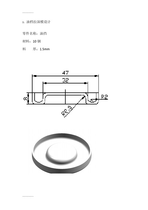
1、油档拉深模设计零件名称:油挡
材料:10钢
料厚:1.5mm
2、撬板冲压工艺及模具设计零件简图如图所示
生产批量:大批量
材料:Q235
材料厚度:4mm
精度等级:IT14级
3、推力滚子轴承外罩冲压模具设计
推力滚子轴承外罩的材料:08或10钢,年产量:6万件。
4、金属盖落料拉深工艺与模具设计
零件名称:盖
生产批量:大批量
材料:镀锌铁皮
厚度:1mm
5、弹簧片五金冲压模设计零件名称:弹簧片
材料:QSn6.5-0.1y
厚度:0.5mm
6、接线片五金模设计
名称:接线片 材料:
7、前灯反光碗拉伸模设计零件名称:前灯反光碗
材料:紫铜
料厚:0.5mm
8、盖复合模设计
零件名称:端盖材料:10钢
料厚:0.5mm。
QC工程图-冲压
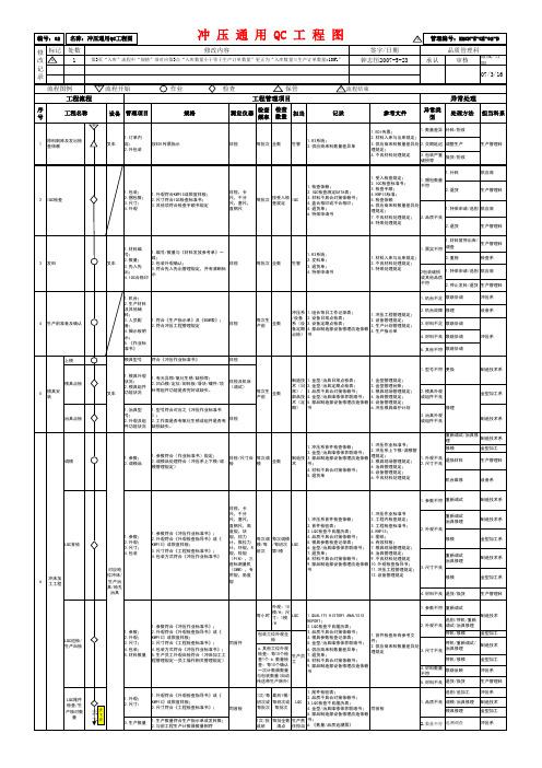
生产管理科
供应商
生产管理科
3
发料
叉车
1.材料编 号; 2.数量; 3.先入先 出; 4.IQC合格印
1.编号/数量与《材料发放参考单》一 致; 2.包装外观确认; 目视 3.符合先入先出管理规定,并有清晰标 示
1.票实不符 每批次 全数 生管 1.R3系统; 2.发料单; 3.退货单; 4.特采申请书 1.材料入库与出库规定; 2.不良材料处理规定; 3.特采处理规定
07/3/16
S
流程图例 工程流程
序号 工程名称
S
流程开始
作业
检查
检查 测定仪器 频率
保管 工程管理项目
检查 数量
E
流程结束
异常处理
担当 记录 参考文件 异常类型 处理方法 担当科系
设备 管理项目
规格
1
原料到库及发出检 查依赖
叉车
1.订单内 容; 2.外包装
按EDI传票指示
目视
每批次 全数
生管
1.R3系统; 2.供应商来料数量差异单
1.符合《生产指示单》及《BOM表》; 2.符合冲压工程管理规定
目视
每次生 全数 产前
1.冲压工程管理规定; 2.设备管理规定; 3.生产计划管理规定; 4.生产指示单
冲压系
上模
制造技术系
模具点检 5 模具安 装 叉车
1.模具外观 状况; 2.模具组件 功能状况
1.有无异物/氧化生锈/缺损等; 2.凹凸模/定位/卸料板/滑块/镶件/顶 针等组件功能是否完好或缺失。
目视及机床 (调试)
每次生 全数 产前
治具点检
1.治具型 号; 2.外观及组 件功能状况
1.型号符合对应之《冲压作业标准书 》; 目视 2.工作面是否有氧化生锈或组件是否有 缺损缺失。
冲压模具图纸

检验图表a 别 零件名称 字件与 工序号 第5页止动作4共5页发字anWU硬度A3项目号检聆内容©SXM1各主要尺寸游标卡尺日装工名九 工苫俎粒 工苫室主各车间主任 主w 工艺库10.模具总装配图” 即* 1]\ 4 5#CB7O-86M蹈”X__S:科销_?_454:B/T7H9. 10-94博谢・445fi HRC24~7M JB/T765O. 5—"M T垫板]加;MC54~58JWT76" A"125X125X67g凸p4模固定]454HRC24~28J即T7* 3,1一“U 5X125X14?a弹替14而 E iMnA HR。
4g 技JB/T71B7, 6T5a a1454125X1?京工1g®1G T 12HRCM〜招JB/T76O, 3-31lt$X125X141IQ隼24hH CE1 ]?-36中】oXwIE三145#HRC2 1〜窗JB/T7613. A*L25X125X12ICn凸慢固定板145#HRC2”28JB/T7M2 1-31psxi^xU~T' \61HT?"D CS/T2355, 5-30125X12SXS0215阴Tt拈145#CBJ15-E6 4 4X14I 4推杆145#HRC"~ 我13JL023Ah F JB/T764L J-54□JL TlDA HRC56〜如GBZTSB25-9J 12U第口牛发145#J2iQ ;注钧245*CW 19-86L小】0X35Q盥钉一44”CE7O-E6M3X6 0s摩套2GCrl5 HRC62〜6。
C B/T2B6J,6-9O r* 23X807 导程26015HEC稣〜g GE/T2861. 1-5Q4*22X150二一]T8A HRC"〜5gS客翰145# HRC4»4g GB/T7649. 1Q-W4 i51模1Crl2 HRC5H~W1J_ J|§!:生冬2454 GEilWt力】OX2 H螺钉443# GB70-E5MSX4DI 、模座板1HT20Q GB/T2355-90I S5XI>5X353敏呈材料德处曼阮淮代号舂若H寸舌括记描图KvF在对审核检3EZ止动件冲孔落料复合模型别]枣组件号篁稿号车间同意第版设备型号比例I 1:1怏12贡第1页成都航院图4模具装配图图5凸凹模技术要求1 .上,下面光滑无毛刺,平行度为0.02口2 .材料为T1QA,需辟火HRC 即-64.3・帝*号的尺寸按时应尺寸及间隙值配伍凸凹模1成都航院设计材H基£ 比例 第电p:要单前ErK_11:11111.模具零件图 R297^Ulm L困6年H&德图7落料凹模板技术要求L 表面光滑无毛刺。
冲压件加工图纸

冲压件加工图纸冲压件加工图纸是冲压件生产过程中的重要文件,它如同一张精确的地图,为整个生产流程指明了方向。
一张清晰、准确、完整的冲压件加工图纸,能够有效地指导生产人员进行操作,确保冲压件的质量和精度符合要求。
首先,让我们来了解一下冲压件加工图纸的基本构成要素。
它通常包括零件的视图、尺寸标注、公差要求、材料规格、表面处理要求以及工艺说明等。
视图是冲压件加工图纸的核心部分之一。
通过不同的视图,如主视图、俯视图、侧视图等,可以全面、清晰地展示零件的形状和结构。
这些视图需要准确地反映零件的几何形状,包括轮廓、孔洞、凸台、凹槽等特征。
同时,视图的比例要选择合适,以确保在图纸上能够清晰地呈现零件的细节,又不至于使图纸过于复杂。
尺寸标注是另一个关键要素。
准确无误的尺寸标注是保证冲压件能够符合设计要求的重要依据。
尺寸标注应包括零件的线性尺寸、角度尺寸、直径尺寸等。
而且,每个尺寸都需要有明确的公差要求,以允许在生产过程中存在一定的制造误差,但又能保证零件在装配和使用时的性能。
公差的选择需要综合考虑零件的功能、制造工艺的能力以及成本等因素。
过小的公差会增加生产成本,过大的公差则可能影响零件的性能和装配精度。
材料规格的标注也至关重要。
不同的材料具有不同的性能和加工特点,因此需要在图纸上明确指定所用材料的牌号、规格和状态。
例如,是选用冷轧钢板、热轧钢板还是不锈钢板,材料的厚度是多少,硬度要求如何等。
表面处理要求也是不可忽视的一部分。
这可能包括镀锌、喷漆、抛光等处理方式,以提高零件的耐腐蚀性、外观质量或其他特定性能。
工艺说明则为生产过程提供了具体的操作指南。
它可能包括冲压的工序顺序、模具的选择、冲压设备的参数要求、检验的方法和标准等。
在绘制冲压件加工图纸时,需要遵循一系列的标准和规范。
这些标准和规范旨在确保图纸的一致性、可读性和通用性。
例如,在尺寸标注方面,要遵循国家标准或行业标准的规定,使用统一的符号和缩写。
线条的粗细、字体的大小和类型等也都有相应的要求。
冲压模具图绘制完整ppt

谢谢观看
弯曲模具设计与制造 之
冲压模具图绘制
工作对象:
AutoCAD软件 产品及其模具
工作目标:
料带图绘制 模具总装图绘制 弯曲模凸凹模绘制 弯曲模模板图绘制 模具其它零件图绘制
知识及工具准备:
弯曲模设计程序 机械制图 AutoCAD软件使用
教学方法:
多媒体讲授 实物零件分析 生产现场参观 机房设计指导
教学结果:
掌握料带图绘制要求 掌握弯曲模具设计的流程
AutoCAD软件使用
掌握弯曲模具结构图的绘制要求 掌握弯曲模具设计的流程
掌握弯曲模具凸凹模绘制要求 AutoCAD软件 产品及其模具
AutoCAD软件 产品及其模具 掌握弯曲模具结构图的绘制要求
掌握弯曲模具结构图的绘制要求 掌掌握弯曲模具设计的流程
掌握弯曲模具设计的流程 AutoCAD软件 产品及其模具
AutoCAD软件使用
AutoCAD软件 产品及其模具 AutoCAD软件 产品及其模具 掌握弯曲模具凸凹模绘制要求 AutoCAD软件使用
考核与评估:
AutoCAD绘制冲模的方法与技巧 简单弯曲模具的绘制 模具绘制流程
冲压件工程图

SLAC Pub 7060Some Alignment Considerations for the Next Linear ColliderRobert E. Ruland, Stanford Linear Accelerator Center, Stanford, CA 943091.0 INTRODUCTIONNext Linear Collider type accelerators require a new level of alignment quality. The relative alignment of these machines is to be maintained in an error envelope dimensioned in micrometers and for certain parts in nanometers. In the nanometer domain our terra firma cannot be considered monolithic but compares closer to jelly. Since conventional optical alignment methods cannot deal with the dynamics and cannot approach the level of accuracy, special alignment and monitoring techniques must be pursued.2.0 COMPONENT PLACEMENT TOLERANCESComponent placement tolerance specifications define the alignment operation. The definition of these tolerances has changed over recent years, resulting in significantly looser specifications. At the same time, the alignment requirements of NLC type machines are intrinsically more demanding, effectively offsetting these reductions.The available space here does not allow a detailed discussion of all parts of an NLC design. While the following discussion will focus on the main linac damping ring alignment, most of it is nonetheless directly applicable to the other machine parts.2.1 DefinitionsOriginally, alignment tolerances were calculated as the offset of a single component resulting in an intolerable loss of luminosity. This seemed a reasonable way to proceed and immediately gave relative sensitivities of component placement. However, this method had two flaws: it failed to take into account that, firstly, not just one but all elements are out of alignment simultaneously, and secondly, that sophisticated orbit and tune correction systems are applied to recover the lost luminosity. Permissible alignment errors, random or systematic, under these more realistic assumptions are much harder to estimate because they require an understanding of allconceivable interactive effects that go into a simulation and a detailed scenario of tuning and correcting. The continued increase in available computing power has made it possible to calculate the simultaneous offsets of all components. Operating experience from the present generation of colliders has yielded significant advances in orbit tuning and correcting. On this basis, alignment tolerances can be defined as the value of placement errors which, if exceeded, make the machine uncorrectable. Experience with higher order optical systems has shown that alignment tolerances derived in this manner tend to be about an order of magnitude looser than before.’2.2 NLC Linac TolerancesAlignment tolerances according to the first and the most recent definitions have been computed2 and are plotted in Fig. 1. The first curve shows the placement tolerances required to keep dispersion losses under a tolerable 3%, i.e. the machine would operate to design specifications. The placement requirements for adjacent components are a very tight 32.3. Measurement Quality EstimateTo estimate what alignment accuracy could be achieved in a conventional alignment procedure for the main linac, the process has been simulated. Fig. 4 shows the resulting tolerance curve. Comparing Fig. 1 to Fig. 2, one can see, that conventional alignment can support the ab initio alignment requirements but not the running tolerance requirements.Fig. 2. Quadrupole alignment tolerances vs. alignment accuracy3.0 DATUM DEFINITIONSince the earth is spherical, a slicethrough an equipotential surface, i.e. asurface where water is at rest, shows anellipse. For a project the size of an NLC,this has significant consequences.Fig. 3. Effect of earth curvature on linear and circularaccelerators3.1 Tangential Plane or Equipotential SurfaceTraditionally, accelerators were built in atangential plane, sometimes slightly tilted toaccommodate geological formations. All pointsaround an untilted circular machine lie at the sameFig. 4. Three plane lay-outheight (Fig. 3), but a linear machine such as theNLC cuts right through the equipotential iso-lines. The center of a 30 km linear accelerator is 17 m below the end points. To alleviate the problems one could build the accelerator on more than one plane, e.g. building the linacs and the final focus/detector section on three separate planes reduces the sagitta to 1.9 m (Fig. 4). To avoid the “height” difference completely, one would need to build the machine along an equipotential surface.3.2 Lay-out DiscussionSince most surveying instruments work relative to gravity, the “natural” solution is a lay-out which follows the surface generated by equal gravity, the equipotential surface, although, for conventional alignment methods, the choice of a tangential surface adds just one additional correction. The choice of lay-out surface does have a major impact upon which special alignment methods can be used: a diffraction optics Fresnel plate alignment system requires a straight line of sight, but a hydrostatic level system can not accommodate height differences of more than a few centimeters.4.0 SPECIAL ALIGNMENT SYSTEMSThe conventional alignment accuracy can be improved by adding alignment systems to the measurement plan which are optimized for the measurement of the critical dimension. The key element of any of these alignment schemes is to generate a straight line reference. Fig. 5 gives an overview of straight line reference systems categorized by their working principle.3 Most of these systems can also be used to establish on-line monitoring systems.4.1 Mechanical Reference LineA stretched wire is used to represent a straight line. While in the horizontal plane a wire projects to a first order a straight line, in the vertical plane it follows a hyperbolic shape due toFig. 5. Straight line reference systemsgravitational forces. The deviation from a straight line in the vertical is a function of the wire’s weight per unit length, wire length and tension. A 45 m spring steel wire with 0.5 mm diameter under a maximum tension has a sagitta of about 6 mm. A comparable wire made of a silicon-carbide material4 which has the same tensile strength but at only one tenth of the spring steel’s weight per unit length, creates a sagitta of only 0.6 mm. For very accurate measurements, deviations of a wire from a straight line in the horizontal plane must also be considered. These deviations are created by internal bending moments caused by molecular stress of the material. The bending moments can be reduced to negligible size by heat-treating the wire or by stretching it into the yield range.4. 1. 1. Optical Detection The “Light Shadow Technique”(Fig. 6) is implemented with a variety of detectors and canprovide very cost effective solutions, excellent range andresolution. At LLNL, a GaAs infrared emitting diode Fig. 6. Light shadow technique illuminating a silicon phototransistor across a 2.5 mm gap combination was used to measure the deflection of a wire in an electro-magnetic field.5 This set up was part of a system to align the solenoid focus magnets on the ETA-II linear induction accelerator. To stabilize drift problems, the phototransistor was replaced with CdS photoconductors.6 The resolution proved better than 14.1.2. Electrical Detection Electrical pick-ups useinductive or capacitive techniques to measure thewire position. A very simple inductive system wasdeveloped at KEK to support the alignment of theATF linac. The reference wire carries a 60 kHzsignal which is picked up by two coils on either sideof the wire (Fig. 8).8 The differential signal is ameasure for the relative wire position. The accuracyover the measurement range of 5 mm is better than± 30ESRF and CERN, in collaboration with the French company Fogale Nanotech, have developed capacitive sensors. The CERN sensor is bi-axial and resolves the wire position over a range of 2.5 mm to ± 1alignment of components to about ± 50In its simplest form, a laser beam images a spot on a PSD, QD or CCD array, allowing a direct position read-out to fewSLAC Linac/FFTB AlignmentSystem.12,13 The reference line of aFresnel system is defined by the pinhole and the center of the detectorplane (Fig. 12). The Fresnel zone Fig. 12. Fresnel alignment systemplate (Fig. 13) focuses the diffuse light onto the detector, forming an interference pattern (Fig. 14). The design parameters of the zone plates, size, width of strips, and gaps, are a function of the wavelength of the light source, image and object distances, and resolution. Only one Fresnel lens can be in the light path at any time. To incorporate more monitor stations into the system, the zone plates must be mounted on hinges so that actuators can flip the plates in and out of the light path. Since refraction would distort the fringe images to noise, the light path must be in a vacuum vessel.T h e F F T B a l i g n m e n tsystem’s Fresnel zoneplates, which, as anextension to the linacalignment system, are about3.2 - 3.4 km from the detec-tor, can resolve the motionof a zone plate to 5155.0 ERROR PROPAGATIONS WITH ADDITIONAL SYSTEMS5.1. Stretched WireFor the purpose of estimating the error propagation of a wire system over the length of a possible NLC linac the lay-out as sketched in Fig. 16 was assumed. A double overlapping wire arrangement is necessary since it was found that in order to preserve a position survey accuracy of ± 5VI/460The improved wire curve assumes that it will be possible to achieve the present FFTB wire accuracy for a 100 m long wire. This system would be able to fully support the alignment needs.Fig. 17. Wire alignment accuracies5.2. Hydrostatic Level SystemTo simulate the effect of supporting the alignment with a hydrostatic level system, two cases need to be considered. If the machine would be built on a tangential plane, one hydrostatic level system cannot accommodate the height difference. Therefore, the simulation assumes individual 500 m long sections set up like a stair. The second case assumes an equipotential surface as reference plane allowing one continues system. Fig. 18 shows the simulation results.Fig. 18. Hydrostatic alignment accuraciesVI/4616.0 SUMMARYAlthough the NLC requires alignment tolerances an order of magnitude tighter than required for existing machines, results from a conventional alignment will be sufficient to make the NLC correctable. It was shown also that more sophisticated alignment systems can very likely accommodate the operational requirements. While the beam itself is the ultimate judge of alignment, beam based alignment requires costly beam time. To maximize luminosity, the investment in more sophisticated alignment tools may well pay off.1Fischer, G., Alignment and Vibration Issues in TeV Linear Collider Design, Proc. International Conference on High Energy Accelerators, Tsukuba, 1989, SLAC-PUB 5024.2Adolphsen, C., A Linac Design for the NLC, Proc. 1995 PAC, Dallas, 1995, in print.3Schwarz, W. ed., Vermessungsverfahren im Maschinen- und Anlagenbau, Schriftenreihe DVW, Wittwer Verlag, 13/1995, p. 128.4Made by TEXTRON Specialty Materials.5Griffith, L., Progress in ETA-II Magnetic Field Alignment using Stretched Wire and Low Energy Electron Beam Techniques, Proc. Linac Conference, Albuquerque, 1990.6Griffth, L., private communication.7Gervaise, J. & E. Wilson, High Precision Geodesy Applied to CERN Accelerators, Applied Geodesy for Particle Accelerators, CERN 87-01, Geneva, 1987, p. 162.8Hayano, H., private communication.9Ruland, R., et al., A Dynamic Alignment System for the Final Focus Test Beam, Proc. Third IWAA, Annecy, 1993, pp. 243-4.l0Fuss, B., The SLAC Pyramid Magnet Monitoring System, Internal Report, Unpublished11Takeuchi, Y., ATF Alignment, Proc. KEK/SLAC X-Band Collider Design Mini-workshop, SLAC, 1994, SLAC-R-95-456.12Hermannsfeldt, W., Precision Alignment Using a System of Large Rectangular Fresnel Lenses, Applied Optics, 7, 1968, pp. 995-1005, SLAC-PUB 496.13Ruland, R., op.cit., pp. 246-251.VI/46214Griffith, L., et al., Magnetic Alignment and the Poisson alignment reference system. Rev. Sci. Instrum., 61 (8), 1990, pp. 2138-2154.15Roux, D., A historical First on Accelerator Alignment, Proc. Third IWAA, Annecy, 1993, pp. 88-91.。
L型工件冲压模具设计(含全套CAD图纸)Word

说明书设计题目:L型工件冲压模具设计专业年级:机械设计制造及其自动化2011级学号:姓名:指导教师、职称:2015 年 05 月 27 日目录摘要 (I)Abstract (II)1 引言 ........................................................................................................................................................ - 3 -1.1本设计的目的与意义................................................................................................................... - 1 -1.2冲压模具在国内外发展概况及存在问题................................................................................... - 1 -1.3课题应解决的主要问题、指导思想和应达到的技术要求....................................................... - 2 -2产品的结构分析和构成.......................................................................................................................... - 2 -2.1产品设计 ...................................................................................................................................... - 3 -2.2制作图及产品基本要求............................................................................................................... - 3 -2.3冲裁件的工艺分析....................................................................................................................... - 4 -2.4确定工艺方案............................................................................................................................... - 4 -3.计算冲裁力、压力中心和选用压力机.................................................................................................. - 5 -3.1排样方式的确定及材料利用率的计算....................................................................................... - 6 -3.2计算冲裁力、卸料力................................................................................................................... - 7 -3.3压力机的选用............................................................................................................................... - 8 -3.4确定模具压力中心....................................................................................................................... - 9 -3.5冲裁模间隙与凸凹模刃口尺寸及公差的计算......................................................................... - 10 -4.设计需要的模具 ................................................................................................................................... - 12 -4.1确定模具的结构......................................................................................................................... - 13 -4.2橡胶的选用 ................................................................................................................................ - 14 -4.3模柄的尺寸选用......................................................................................................................... - 16 -4.4凸模的外形尺寸......................................................................................................................... - 17 -4.5凸模强度校核............................................................................................................................. - 18 -4.6落料凹模尺寸的计算................................................................................................................. - 18 -4.7定位零件 .................................................................................................................................... - 19 -4.8卸料装置 .................................................................................................................................... - 19 -4.9模具的闭合高度......................................................................................................................... - 19 -结束语 ...................................................................................................................................................... - 19 -参考文献 .................................................................................................................................................. - 20 -致谢 .......................................................................................................................................................... - 22 -摘要本设计压模进行了冲孔、落料级进模的设计。
冲压模具设计装配图.
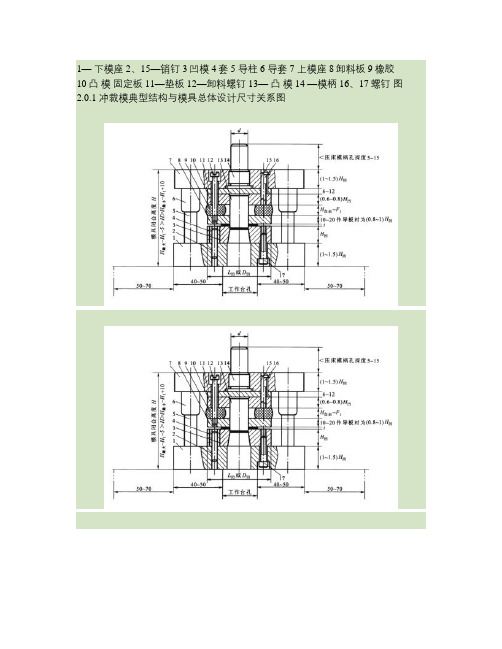
1—下模座2、15—销钉3凹模4套5 导柱 6 导套 7 上模座 8卸料板9橡胶10凸模固定板 11—垫板12—卸料螺钉13—凸模14 —模柄 16、17螺钉图2.0.1 冲裁模典型结构与模具总体设计尺寸关系图复合模的基本结构1—凸模;2—凹模;3—上模固定板;4、16—垫板;5—上模座;6—模柄;7—推杆; 8—推块; 9—推销;10—推件块;11、18—活动档料销;12—固定挡料销;13—卸料板14—凸凹模;15—下模固定板;17—下模座;19—弹簧1-下模座;2、5-销钉;3-凹模;4-凸模 1-凹模;2-凸模;3-定位钉;4-压料板;5-靠板 6-上模座;7-顶杆;8-弹簧;图3.4.2 L形件弯曲模 9、11-螺钉;10-可调定位板1.冲裁间隙过大时,断面将出现二次光亮带。
( ×)2.冲裁件的塑性差,则断面上毛面和塌角的比例大。
( ×)3.形状复杂的冲裁件,适于用凸、凹模分开加工。
( ×)4.对配作加工的凸、凹模,其零件图无需标注尺寸和公差,只说明配作间隙值。
( ×)5.整修时材料的变形过程与冲裁完全相同。
( ×)6.利用结构废料冲制冲件,也是合理排样的一种方法。
(∨)7.采用斜刃冲裁或阶梯冲裁,不仅可以降低冲裁力,而且也能减少冲裁功。
( ×)8.冲裁厚板或表面质量及精度要求不高的零件时,为了降低冲裁力,一般采用加热冲裁的方法进行。
(∨)9.冲裁力是由冲压力、卸料力、推料力及顶料力四部分组成。
( ×)10.模具的压力中心就是冲压件的重心。
( ×)11.冲裁规则形状的冲件时,模具的压力中心就是冲裁件的几何中心。
( ×)12.在压力机的一次行程中完成两道或两道以上冲孔(或落料)的冲模称为复合模。
×13.凡是有凸凹模的模具就是复合模。
( ×)14.在冲模中,直接对毛坯和板料进行冲压加工的零件称为工作零件。
工件冲压模具设计(含全套CAD图纸)

L型工件冲压模具设计(含全套CAD图纸)说明书设计题目:L型工件冲压模具设计专业年级:机械设计制造及其自动化2011级学号:姓名:指导教师、职称:2015 年05 月27 日目录摘要 (I)Abstract ................................................................ I I 1 引言............................................................... - 1 -1.1本设计的目的与意义......................................... - 1 -1.2冲压模具在国内外发展概况及存在问题......................... - 1 -1.3课题应解决的主要问题、指导思想和应达到的技术要求 ........... - 2 - 2产品的结构分析和构成 ............................................... - 3 -2.1产品设计................................................... - 3 -2.2制作图及产品基本要求....................................... - 3 -2.3冲裁件的工艺分析........................................... - 4 -2.4确定工艺方案............................................... - 5 -3.计算冲裁力、压力中心和选用压力机................................... - 6 -3.1排样方式的确定及材料利用率的计算........................... - 6 -3.2计算冲裁力、卸料力......................................... - 7 -3.3压力机的选用............................................... - 8 -3.4确定模具压力中心........................................... - 9 -3.5冲裁模间隙与凸凹模刃口尺寸及公差的计算.................... - 10 -4.设计需要的模具.................................................... - 13 -4.1确定模具的结构............................................ - 13 -4.2橡胶的选用................................................ - 14 -4.3模柄的尺寸选用............................................ - 16 -4.4凸模的外形尺寸............................................ - 17 -4.5凸模强度校核.............................................. - 18 -4.6落料凹模尺寸的计算........................................ - 18 -4.7定位零件.................................................. - 19 -4.8卸料装置.................................................. - 19 -4.9模具的闭合高度............................................ - 19 - 结束语.............................................................. - 20 - 参考文献............................................................ - 21 - 致谢................................................................ - 23 -摘要本设计压模进行了冲孔、落料级进模的设计。
夹子冲压件设计
CHANGZHOU INSTITUTE OF TECHNOLOGY毕业设计说明书题目:夹子冲压件设计二级学院(直属学部):专业:班级:学生姓名:学号:指导教师姓名:职称:评阅教师姓名:职称:2014 年06月常州工学院毕业设计摘要本次毕业设计课题来源于生产实际,具有很强的指导意义。
零件采用不锈钢作为原材料,厚度为0.5毫米。
首先是对制品进行测绘,画出制品的二维工程图。
并对冲压件的工艺分析,完成了工艺方案的确定。
对零件进行排样图的设计,完成了材料利用率的计算。
再进行冲裁工艺力的计算和冲裁模工作部分的设计计算,对选择冲压设备提供依据。
最后对主要零部件的设计和标准件的选择,为本次设计模具的绘制和模具的成形提供依据,以及为装配图各尺寸提供依据。
通过前面的设计方案画出模具各零件图和装配图。
本次设计阐述了模具的结构设计及工作过程。
本模具性能可靠,运行平稳,提高了产品质量和生产效率,降低劳动强度和生产成本。
关键词:冲压弯曲模具结构夹子冲压件设计目录第1章课题简介 (1)第2章工艺分析 (2)2.1零件工艺分析 (2)2.2工艺方案的确定 (2)2.3工艺参数的确定 (2)第3章工作力的计算及压力机的选择 (6)3.1冲压力的计算 (6)3.2粗选压力机 (7)3.3计算压力中心 (7)第4章填写冲压工序卡 (8)第5章模具结构设计 (9)5.1模具结构形式的选择 (9)5.2模具结构的分析与说明 (9)5.3模具工作部分的尺寸和公差的确定 (9)5.4模具结构设计 (12)5.4.1凹模周界尺寸计算 (12)5.4.2选择模架及确定其他冲模零件的有关标准 (12)5.4.3落料凸模的强度和刚度校核 (12)5.4.4卸料.压边弹性元件的确定 (12)5.5校核压力机安装尺寸 (13)第6章弯曲模具的设计 (14)6.1制件弯曲工艺分析 (14)6.2冲压工艺参数的确定。
(14)第7章弯曲模的结构设计 (16)7.1模具结构的分析说明 (16)7.2弯曲模的卸料装置的设计说明 (16)第8章弯曲模的工作尺寸计算 (18)结论 (21)致谢 (22)参考文献 (23)常州工学院毕业设计第1章课题简介零件分析说明:零件形状及其一般要求制件如图1-1所示,材料为不锈钢,材料厚度为0.5mm,制件尺寸精度按图纸要求,未注按IT12级,生产纲领年产10万件。
L型工件冲压模具设计(含全套CAD图纸)

说明书设计题目:L型工件冲压模具设计专业年级:机械设计制造及其自动化2011级学号:姓名:指导教师、职称:2015 年05 月27 日目录摘要 (I)Abstract (II)1 引言 ............................................................... - 1 -1.1本设计的目的与意义 ............................................ - 1 -1.2冲压模具在国内外发展概况及存在问题 ............................ - 1 -1.3课题应解决的主要问题、指导思想和应达到的技术要求 .............. - 2 - 2产品的结构分析和构成................................................ - 3 -2.1产品设计 ...................................................... - 3 -2.2制作图及产品基本要求 .......................................... - 3 -2.3冲裁件的工艺分析 .............................................. - 4 -2.4确定工艺方案 .................................................. - 4 -3.计算冲裁力、压力中心和选用压力机 ................................... - 6 -3.1排样方式的确定及材料利用率的计算 .............................. - 6 -3.2计算冲裁力、卸料力 ............................................ - 7 -3.3压力机的选用 .................................................. - 8 -3.4确定模具压力中心 .............................................. - 9 -3.5冲裁模间隙与凸凹模刃口尺寸及公差的计算 ....................... - 10 -4.设计需要的模具 .................................................... - 13 -4.1确定模具的结构 ............................................... - 13 -4.2橡胶的选用 ................................................... - 14 -4.3模柄的尺寸选用 ............................................... - 16 -4.4凸模的外形尺寸 ............................................... - 17 -4.5凸模强度校核 ................................................. - 18 -4.6落料凹模尺寸的计算 ........................................... - 18 -4.7定位零件 ..................................................... - 19 -4.8卸料装置 ..................................................... - 19 -4.9模具的闭合高度 ............................................... - 19 - 结束语 .............................................................. - 20 - 参考文献 ............................................................ - 21 - 致谢 ................................................................ - 22 -摘要本设计压模进行了冲孔、落料级进模的设计。
- 1、下载文档前请自行甄别文档内容的完整性,平台不提供额外的编辑、内容补充、找答案等附加服务。
- 2、"仅部分预览"的文档,不可在线预览部分如存在完整性等问题,可反馈申请退款(可完整预览的文档不适用该条件!)。
- 3、如文档侵犯您的权益,请联系客服反馈,我们会尽快为您处理(人工客服工作时间:9:00-18:30)。
SLAC Pub 7060Some Alignment Considerations for the Next Linear ColliderRobert E. Ruland, Stanford Linear Accelerator Center, Stanford, CA 943091.0 INTRODUCTIONNext Linear Collider type accelerators require a new level of alignment quality. The relative alignment of these machines is to be maintained in an error envelope dimensioned in micrometers and for certain parts in nanometers. In the nanometer domain our terra firma cannot be considered monolithic but compares closer to jelly. Since conventional optical alignment methods cannot deal with the dynamics and cannot approach the level of accuracy, special alignment and monitoring techniques must be pursued.2.0 COMPONENT PLACEMENT TOLERANCESComponent placement tolerance specifications define the alignment operation. The definition of these tolerances has changed over recent years, resulting in significantly looser specifications. At the same time, the alignment requirements of NLC type machines are intrinsically more demanding, effectively offsetting these reductions.The available space here does not allow a detailed discussion of all parts of an NLC design. While the following discussion will focus on the main linac damping ring alignment, most of it is nonetheless directly applicable to the other machine parts.2.1 DefinitionsOriginally, alignment tolerances were calculated as the offset of a single component resulting in an intolerable loss of luminosity. This seemed a reasonable way to proceed and immediately gave relative sensitivities of component placement. However, this method had two flaws: it failed to take into account that, firstly, not just one but all elements are out of alignment simultaneously, and secondly, that sophisticated orbit and tune correction systems are applied to recover the lost luminosity. Permissible alignment errors, random or systematic, under these more realistic assumptions are much harder to estimate because they require an understanding of allconceivable interactive effects that go into a simulation and a detailed scenario of tuning and correcting. The continued increase in available computing power has made it possible to calculate the simultaneous offsets of all components. Operating experience from the present generation of colliders has yielded significant advances in orbit tuning and correcting. On this basis, alignment tolerances can be defined as the value of placement errors which, if exceeded, make the machine uncorrectable. Experience with higher order optical systems has shown that alignment tolerances derived in this manner tend to be about an order of magnitude looser than before.’2.2 NLC Linac TolerancesAlignment tolerances according to the first and the most recent definitions have been computed2 and are plotted in Fig. 1. The first curve shows the placement tolerances required to keep dispersion losses under a tolerable 3%, i.e. the machine would operate to design specifications. The placement requirements for adjacent components are a very tight 32.3. Measurement Quality EstimateTo estimate what alignment accuracy could be achieved in a conventional alignment procedure for the main linac, the process has been simulated. Fig. 4 shows the resulting tolerance curve. Comparing Fig. 1 to Fig. 2, one can see, that conventional alignment can support the ab initio alignment requirements but not the running tolerance requirements.Fig. 2. Quadrupole alignment tolerances vs. alignment accuracy3.0 DATUM DEFINITIONSince the earth is spherical, a slicethrough an equipotential surface, i.e. asurface where water is at rest, shows anellipse. For a project the size of an NLC,this has significant consequences.Fig. 3. Effect of earth curvature on linear and circularaccelerators3.1 Tangential Plane or Equipotential SurfaceTraditionally, accelerators were built in atangential plane, sometimes slightly tilted toaccommodate geological formations. All pointsaround an untilted circular machine lie at the sameFig. 4. Three plane lay-outheight (Fig. 3), but a linear machine such as theNLC cuts right through the equipotential iso-lines. The center of a 30 km linear accelerator is 17 m below the end points. To alleviate the problems one could build the accelerator on more than one plane, e.g. building the linacs and the final focus/detector section on three separate planes reduces the sagitta to 1.9 m (Fig. 4). To avoid the “height” difference completely, one would need to build the machine along an equipotential surface.3.2 Lay-out DiscussionSince most surveying instruments work relative to gravity, the “natural” solution is a lay-out which follows the surface generated by equal gravity, the equipotential surface, although, for conventional alignment methods, the choice of a tangential surface adds just one additional correction. The choice of lay-out surface does have a major impact upon which special alignment methods can be used: a diffraction optics Fresnel plate alignment system requires a straight line of sight, but a hydrostatic level system can not accommodate height differences of more than a few centimeters.4.0 SPECIAL ALIGNMENT SYSTEMSThe conventional alignment accuracy can be improved by adding alignment systems to the measurement plan which are optimized for the measurement of the critical dimension. The key element of any of these alignment schemes is to generate a straight line reference. Fig. 5 gives an overview of straight line reference systems categorized by their working principle.3 Most of these systems can also be used to establish on-line monitoring systems.4.1 Mechanical Reference LineA stretched wire is used to represent a straight line. While in the horizontal plane a wire projects to a first order a straight line, in the vertical plane it follows a hyperbolic shape due toFig. 5. Straight line reference systemsgravitational forces. The deviation from a straight line in the vertical is a function of the wire’s weight per unit length, wire length and tension. A 45 m spring steel wire with 0.5 mm diameter under a maximum tension has a sagitta of about 6 mm. A comparable wire made of a silicon-carbide material4 which has the same tensile strength but at only one tenth of the spring steel’s weight per unit length, creates a sagitta of only 0.6 mm. For very accurate measurements, deviations of a wire from a straight line in the horizontal plane must also be considered. These deviations are created by internal bending moments caused by molecular stress of the material. The bending moments can be reduced to negligible size by heat-treating the wire or by stretching it into the yield range.4. 1. 1. Optical Detection The “Light Shadow Technique”(Fig. 6) is implemented with a variety of detectors and canprovide very cost effective solutions, excellent range andresolution. At LLNL, a GaAs infrared emitting diode Fig. 6. Light shadow technique illuminating a silicon phototransistor across a 2.5 mm gap combination was used to measure the deflection of a wire in an electro-magnetic field.5 This set up was part of a system to align the solenoid focus magnets on the ETA-II linear induction accelerator. To stabilize drift problems, the phototransistor was replaced with CdS photoconductors.6 The resolution proved better than 14.1.2. Electrical Detection Electrical pick-ups useinductive or capacitive techniques to measure thewire position. A very simple inductive system wasdeveloped at KEK to support the alignment of theATF linac. The reference wire carries a 60 kHzsignal which is picked up by two coils on either sideof the wire (Fig. 8).8 The differential signal is ameasure for the relative wire position. The accuracyover the measurement range of 5 mm is better than± 30ESRF and CERN, in collaboration with the French company Fogale Nanotech, have developed capacitive sensors. The CERN sensor is bi-axial and resolves the wire position over a range of 2.5 mm to ± 1alignment of components to about ± 50In its simplest form, a laser beam images a spot on a PSD, QD or CCD array, allowing a direct position read-out to fewSLAC Linac/FFTB AlignmentSystem.12,13 The reference line of aFresnel system is defined by the pinhole and the center of the detectorplane (Fig. 12). The Fresnel zone Fig. 12. Fresnel alignment systemplate (Fig. 13) focuses the diffuse light onto the detector, forming an interference pattern (Fig. 14). The design parameters of the zone plates, size, width of strips, and gaps, are a function of the wavelength of the light source, image and object distances, and resolution. Only one Fresnel lens can be in the light path at any time. To incorporate more monitor stations into the system, the zone plates must be mounted on hinges so that actuators can flip the plates in and out of the light path. Since refraction would distort the fringe images to noise, the light path must be in a vacuum vessel.T h e F F T B a l i g n m e n tsystem’s Fresnel zoneplates, which, as anextension to the linacalignment system, are about3.2 - 3.4 km from the detec-tor, can resolve the motionof a zone plate to 5155.0 ERROR PROPAGATIONS WITH ADDITIONAL SYSTEMS5.1. Stretched WireFor the purpose of estimating the error propagation of a wire system over the length of a possible NLC linac the lay-out as sketched in Fig. 16 was assumed. A double overlapping wire arrangement is necessary since it was found that in order to preserve a position survey accuracy of ± 5VI/460The improved wire curve assumes that it will be possible to achieve the present FFTB wire accuracy for a 100 m long wire. This system would be able to fully support the alignment needs.Fig. 17. Wire alignment accuracies5.2. Hydrostatic Level SystemTo simulate the effect of supporting the alignment with a hydrostatic level system, two cases need to be considered. If the machine would be built on a tangential plane, one hydrostatic level system cannot accommodate the height difference. Therefore, the simulation assumes individual 500 m long sections set up like a stair. The second case assumes an equipotential surface as reference plane allowing one continues system. Fig. 18 shows the simulation results.Fig. 18. Hydrostatic alignment accuraciesVI/4616.0 SUMMARYAlthough the NLC requires alignment tolerances an order of magnitude tighter than required for existing machines, results from a conventional alignment will be sufficient to make the NLC correctable. It was shown also that more sophisticated alignment systems can very likely accommodate the operational requirements. While the beam itself is the ultimate judge of alignment, beam based alignment requires costly beam time. To maximize luminosity, the investment in more sophisticated alignment tools may well pay off.1Fischer, G., Alignment and Vibration Issues in TeV Linear Collider Design, Proc. International Conference on High Energy Accelerators, Tsukuba, 1989, SLAC-PUB 5024.2Adolphsen, C., A Linac Design for the NLC, Proc. 1995 PAC, Dallas, 1995, in print.3Schwarz, W. ed., Vermessungsverfahren im Maschinen- und Anlagenbau, Schriftenreihe DVW, Wittwer Verlag, 13/1995, p. 128.4Made by TEXTRON Specialty Materials.5Griffith, L., Progress in ETA-II Magnetic Field Alignment using Stretched Wire and Low Energy Electron Beam Techniques, Proc. Linac Conference, Albuquerque, 1990.6Griffth, L., private communication.7Gervaise, J. & E. Wilson, High Precision Geodesy Applied to CERN Accelerators, Applied Geodesy for Particle Accelerators, CERN 87-01, Geneva, 1987, p. 162.8Hayano, H., private communication.9Ruland, R., et al., A Dynamic Alignment System for the Final Focus Test Beam, Proc. Third IWAA, Annecy, 1993, pp. 243-4.l0Fuss, B., The SLAC Pyramid Magnet Monitoring System, Internal Report, Unpublished11Takeuchi, Y., ATF Alignment, Proc. KEK/SLAC X-Band Collider Design Mini-workshop, SLAC, 1994, SLAC-R-95-456.12Hermannsfeldt, W., Precision Alignment Using a System of Large Rectangular Fresnel Lenses, Applied Optics, 7, 1968, pp. 995-1005, SLAC-PUB 496.13Ruland, R., op.cit., pp. 246-251.VI/46214Griffith, L., et al., Magnetic Alignment and the Poisson alignment reference system. Rev. Sci. Instrum., 61 (8), 1990, pp. 2138-2154.15Roux, D., A historical First on Accelerator Alignment, Proc. Third IWAA, Annecy, 1993, pp. 88-91.。
