ESP优选新手入门调试指导补全
易语言编程入门教程易语言应用ESP编程入门_图文
易语言编程入门教程易语言应用ESP编程入门_图文导读:就爱阅读网友为您分享以下“易语言应用ESP编程入门_图文”的资讯,希望对您有所帮助,感谢您对的支持!易语言应用ESP实例入门教程前言:为什么要写这个东东当前,计算机编程技术发展日新月异,随着互联网的普及和传输速率的大幅提高,网页程序由于其无需下载安装,升级、维护方便等优势,正在逐步取代传统的桌面应用程序。
而主流的编程工具都已增加了开发网页程序的功能。
那么作为使用易语言的广大编程人员想开发网页程序该怎么办呢?大家别恢心,好在我们易语言界里面藏龙卧虎,有好多高手为易语言开发出了具备各种新功能的支持库,这里面就有“云外归鸟”开发的ESP,它是立足现有易语言编程环境下,开发动态网页程序的最佳选择。
东西是好东西,可是ESP推出2年多了,用的人却很少,坛子里的例程也少的可怜,并且目前还有很多人不知道ESP 这个东西是什么。
究其原因,我想缺乏必要的初级教程和例程,是限制其发展的一个主要问题。
“云外归鸟”在推出这个系统时指出其应用群体是具备一定的网页开发基础以及ASP开发能力的人,也就是坛子里所说的相对“老鸟”,但反过来想一想,会以上两种技能的人还有必要再学ESP来开发网页吗?回答是否定的,即使有,也是出于一种娱乐的心理搞点东西玩一玩。
真正需要用ESP开发的人我想应具备以下一些特点:只用易语言开发软件、其它语言或会一点或不会、没有开发过网页、不想花太多时间再去学习另外一门语言。
具备以上特点的人在易界应该是主体(也就是所说的菜鸟)。
所以很多人想学习,但看了ESP自带的那个成品例程又看不明白,最后还是放弃了。
因此,我个人认为还是有必要推出一个针对“菜鸟”的ESP 入门教程,也就是说,本教程力争把读者群体定位在:一个不会ASP而只会易语言的人,当然,这只是作者自己一厢情愿的想法,到底效果如何,还要等待后面的反应了。
一、什么是ESPESP(易语言Server Pages)即易语言活动服务页,它是易语言编程界高手“云外归鸟”为解决易语言不能编写B/S网页系统软件而推出的。
ESP-r入门教程
London Metropolitan UniversityMasters in Architecture, Energy and Sustainability European Masters in the Integration of RenewableEnergies into BuildingsModule AR52PESP-rLuisa Brotas, Arch PhD ARB RIBAESP-r course notes (version 11.7)1/62Table of Contents (2)1 STRUCTURE OF THE COURSE (3)2 INTRODUCTION (4)3 STRUCTURE OF THE PROGRAM (4)4 GETTING STARTED (6)5 MODEL GEOMETRY (9)5.1 Add a window to a surface (12)6 CONSTRUCTIONS (15)7 OPERATION (17)8 SIMULATION integrated run (21)9 RESULT ANALYSIS graphs (22)10 DATABASE MODIFICATIONS (22)11 A SIMPLE HEATING/COOLING CONTROL (24)12 SIMULATION interactive run (27)13 RESULTS text mode (28)14 AIR FLOW NETWORK (28)14.1. Natural Ventilated Zone - Control for air flow network by opening the windows (36)15 RESULTS (39)15.1 Text description (39)15.2 Graphs (39)16 Bibliography (42)ANNEX 1 Materials database (43)ANNEX 2 Constructions database (46)ANNEX 3 Configuration file (53)ANNEX 4 Results - Hours above a certain value (56)ANNEX 5 Results - Energy Consumption (57)ANNEX 6 Results - Wind data (59)ANNEX 7 Control file (60)ESP-r course notes (version 11.7)2/621 STRUCTURE OF THE COURSE1st DayObjectives:become familiar with the Project Manager and create the mandatory files to perform a simulation.The following tasks will be carried out:•Geometrical definition of two zones (a 2 storey flat);•Definition (selection of defaults) of constructions for the surfaces defined;•Connection of the surfaces if in contact to a zone other than the exterior;•Creation of a window within a wall and attribution of transparent material;•Creation of internal gains as occupants and/or lighting and equipment including operation schedules;•Creation of an infiltration and/or ventilation system (user defined air changes) and its operation schedules;•Use of the simulator module;•Use of the results analysis module.2nd dayObjectives: development of skills by testing optional modules.The tasks to be carried out:•Creation of a multi-layer construction to be used instead of the default;•Creation of a simple heating and/or cooling system.•Result analysis of energy demand.3rd dayobjectives: study of an air flow network on a naturally ventilated model.The tasks to be carried out:•Definition of nodes, components and connections of the flow network;•Definition of a control for the air flow simulating the opening of the windows;•Generation, analysis and storage of results.ESP-r course notes (version 11.7)3/622 INTRODUCTIONESP-r is a transient energy simulation program that allows modelling the energy and fluid flows within a combined building and plant system. Since it is one of the most powerful dynamic thermal simulation tools, its operation is non-trivial. However ESP-r is one of the best validated packages of its kind, so the results very accurately reflect the real building environment, provided the input is well defined.The aim of this 3 days course is to provide you with a basic knowledge of the ESP-r software to perform a building energy analysis. In order to use the software professionally, further studies will be necessary.Before attempting to start working with the program you need to define your objectives and criteria, as well as the expected results.There are several rules that should be f ollowed:•Spend some time and think what you are trying to do before initiating with the software;•Plan in advance what you expect to achieve and what is the best model or tool to reach your aims;•Try to simplify the input of the project. This means a careful choice should be made to the definition of the model. The more complex the input the likelihood the chances of errors for beginners and time consuming that with probably add no significant changes in the results;•Test first on a small scale before aiming at bigger or complex situations. Sometimes a simple analysis might prevent time spending on a solution that does not obtain significant results;•Assign plenty of time to analyse the results and draw your conclusions.3 STRUCTURE OF THE PROGRAMESP-r can be divided into three distinctive parts. The first one is concerned with the establishment of a valid data model (description of the building and/or plant configuration) for the simulation. The second part is related to the simulation processing. The third one with the results recovery and analysis.All the parts are accessed via a Project Manager. This interface also provides access to other program software and support applications such as RADIANCE modules, tutorials, databases or export facilities of the results.ESP-r is structured in different modules. As soon as you start the program the software will create an unique folder or a a set of folders and descriptive files to be accessed later in the program. Table 1 shows the default structure for a fictitious project 'duplex'.ESP-r course notes (version 11.7)4/62Table 1 Folders structureESP-r will also apply different file types with extensions and redirect them to the defined folders. See Table 2.Table 2 Filename conventionESP-r also includes databases which are essential for the simulation(primitive and composite constructions,event profiles,plant components and climatic collections). Depending on the installation they are usually on the following directories and folders:*prm /usr/esru/esp-r/databases/constr.db1*mlc /usr/esru/esp-r/databases/multicon.db1*opt /usr/esru/esp-r/databases/optics.db1ESP-r course notes (version 11.7)5/62*prs /usr/esru/esp-r/databases/pressc.db1*evn /usr/esru/esp-r/databases/profiles.db1*clm /usr/esru/esp-r/climate/clm67*pdb /usr/esru/esp-r/databases/plantc.db1These databases can be accessed and viewed through the Project Manager but depending on the users permissions, they can be modified if copied to a different directory.A good example of use of these databases are the primitives(materials)and multiconstruction (layered construction) databases that can be accessed to select typical materials and construction systems for the building envelope.To p erform a simulation with ESP-r, the following file types may be produced:• A mandatory geometry, construction, and operation file for each zone;• A mandatory system configuration file and an optional configuration control file;•An optional air flow,casual gains,shading/insulation,view factors,surface convection and transparent multi-layered construction file for some or all zones;•An optional fluid flow network description file, a pressure coefficients file;•Fluid flow results and simulation results files.4 GETTING STARTEDLog on a computer and typeesp-ron the command line. This will start ESP-r in its default graphic mode. See Fig. 1.Figure 1: Entry Level of the Project ManagerESP-r course notes (version 11.7)6/62If you are starting a new file, at the Project management select the menu option e create new .You will be asked to define a name (ex. ac ) followed by a choice of a single or standard set of folders where the descriptive and results files will be forward to. See fig. 3. As your model is relatively simple you can select a single directory. For a multiple structure pleaserefer to table 1. As default, the root name will be used for the following files created with the appropriated extension. Do provide a simple description of the project to remember on a later occasion, see fig. 4A file called ac.log will be created, you may want to use it as your “note book”. Other questions will be asked, see fig. 5, as well as general parameters related to the building as site latitude (degrees positive north of equator) and longitude difference (degrees positive east of the time meridian of the place).Examples of longitude difference are -4.1 for Glasgow relative to Greenwich and +2 for NY relative to 75° standard meridian without daylight savings. However, they can be changed ESP-r course notes (version 11.7)7/62Figure 5: Question with the association ofimagesFigure 2: Menu create a new projectFigure 3: Windows defining root name and directory structure (single folder)Figure 4: model descriptionlater as well parameters such as ground reflectance and site exposure.See Model Management > m browse/edit/simulate > b model context in Fig. 6.Figure 6: Model context menuBy this step the program has already created the folder structure and at least the configuration file.Exit the Model management by selecting-exit Project manager.You will be asked to save your data before you exit if you haven't done so before. When you launch the model again you can select the model you are working with its ac.cfg file. On the command line change to the directory created by the software and subdirectory cfg as:cd ac (single directory) or cd ac/cfg (structured) .Now relaunch the software with the indication of the system configuration file as:esp-r -file ac.cfgFor a memory stick mounted at/mnt/sda1for a “ac” project with a configuration file named “ac.cfg” do:cd /mnt/sda1/acesp-r -file ac.cfgIn the initial Model management(see fig. 1)select the menu option m browse/edit/simulate to carry on with setting up the model.The following frame Browse/Edit/Simulate will be the main access point to the selection of the menus such as zones(model geometry and constructions definition), networks and controls.It will also be the interface for actions such as the simulation run and the result analysis.ESP-r course notes (version 11.7)8/625 MODEL GEOMETRY (mandatory)The next step should be to create the geometry of the zones defining the model. See Fig. 7.Figure 7: Model frame of geometrySelect Model Management>m browse/edit/simulate>> B rowse/Edit/Simulate> c composition>> Zones Composition> a geometry and attribut ionetry and attribFigure 8: new zone input optionsESP-r course notes (version 11.7)9/62After defining a name (maximum 12 characters without blanks) and a short description of the zone (64 characters), you may create the geometry with input dimensions, load existing Esp-r or CAD. as in figure 8, and a base geometry as in fig. 9.Four options are then presented after the selection of the input dimension :•rectangular plan – define the coordinates of the origin; the prism width, depth and height. Assuming the prism is orthogonal to the coordinated system width, depth and height are the length of the vector in the X, Y and Z axis respectively. The orientation of the prism may be corrected by the rotation angle measure in degrees anticlockwise from the X axis, see fig. 10.•polygon plan – define the elevation of the base, the elevation of the top and number of walls (excluding the base and top). The coordinates of the base vertex are defined in the X and Y axis (input the coordinates around the base polygon anti-clockwise looking from the top, preferably beginning from the lower left corner of the enclosure). The extrusion rotation is the angle between the site Y-axis and north for the prism assuming anticlockwise as a positive rotation. Note this is different from the box orientation associated with the extruded rectangle.•General 3D – define a set of vertices and then link them together to form surfaces (linked anticlockwise from the lower left when viewing the outside of the surface). You will be prompted for an origin point and a 2m x 2m floor surface will be placed there.ESP-r course notes (version 11.7)10/62Figure 9: zone geometry optionsFrom this initial surface, modify the existing vertices to create the zone enclosure;•bitmap – define the points of the zone by clicking on a image. The plan of the model should have been scanned and saved in a XBM file format and kept on the cfg folder of the project.After creating your first zone the wireframe similar to the one in fig. 11 should appear on the screen.Although the program saves the definitions created it is a good approach to save the model regularly. In this menu save by selecting Zone '1' Geometry> > saveTo create the second zone select - exit this menu to return to the menu one level above Zone Geometry/Attribution and * add/delete/copy.If you decide to add a new zone follow the procedure previous explained.If you decide to copy and existing zone after giving a new name you will be asked to transform and/or rotate the new zone. You may want to wait a little until the model includes further details, such as windows or composition of surfaces, before copying it.If you decide to delete a zone select the zone in question and answer the questions listedfig. 12.ESP-r course notes (version 11.7)11/62Figure 10: input dimension of zoneFigure 11: zone z0 wireframeAs at this point no controls have been defined yet.Figure 12: delete zone links and update configuration fileAs you might have noticed the program creates default surface names for the zone enclosure. The rule is the first vertical surface anticlockwise from origin is Wall-1. Wall-2, 3 and 4 are the following walls in a anticlockwise direction. The top horizontal plane is Top-5 and the ground floor Base-6. To change these to names which are more easily recognised go under Model Management> m browse/edit/simulate>> Browse/Edit/Simulate > c composition>> Zones Composition> a geometry & attribution>> Zone Geometry/Attribution and select a zone. In the menu Zone '1' Geometry select f surface attributes >> Surfaces in z0> a Wall-1. Under the menu Surface Attributes > a surface name change the name (e.g. z0_ext_s as surface in zone z0, being exterior and facing south). Do the same for the remaining surfaces. See fig. 13.In this menu you may also define the construction of this surface by selecting e construction which takes you to the Composite menu of the database, and f environment which takes to the surface boundary of the surface.In the menu Surfaces in z0 you may * attribute many surface attributions, namely composition and boundary condition. For more details on these attributes see section 6. Don't forget to save under Zone 1 Geometry > save to update the '*.geo' file.5.1 Add a window to a surfaceWindows and doors are defined within the surface as a 'hole' to be linked to a vertex of the surface.Go to Model Management> m browse/edit/simulate >> Browse/Edit/Simulate > c composition>> Zones Composition> a geometry & attribution>> Zone Geometry/Attribution > (select a zone)>> Zone 1 Geometry> f surface attributes>> Surfaces in z0> (select surface)>> Surface Attributes > + add glazing/door/opening See fig. 14.ESP-r course notes (version 11.7)12/62Figure 13: zone z0 surface naming and attributes. Note zo_cei_z1 (zone 0 ceiling connecting to zone1) stil has the boundary condition unknown as the second zone hasn't been created yet.If insertion is within the surface you will be prompted for an X Z offset from the lower corner (when viewed from the outside), a width and height. The opening width and height are in metres. See fig. 15.If insertion isat base of the surface you will be asked for a X offset from the left lowercorner of the surface when viewed from the outside, a width and a height.If the insertion is a percentage of parent surface the opening will be a percentage of the surface and will be positioned at the centre of the surface.Before confirming the position, check if the position is ok on the wireframe scheme.See fig. 16. Deleting a window can be a demanding task involving deleting the window surface, the associated vertexes of the parent surface description and the deletion of these vertexes as coordinates.ESP-r course notes (version 11.7)13/62Figure 14: opening geometry menu and optionsFigure 15: coordinates of the window surfaceWhen prompted for a name try to follow a similar approach to the previous definitions (e.g. z0_win_s).You will be asked to select a construction for the inserted surface from the database. Seefig. 17.A warning window appears as a reminder of the modifications occurred to the geometry of the zone.Repeat the process for the following windows.If a surface has more than one window the bounding surface will be revised to flow around the new 'hole'. You will be asked to provide the corner (left or right) to which link the new 'hole'. If the first `hole` is linked to the lower left corner of the bounding surface, the new surface might link to the lower right corner. This convention will hopefully limit the chance of the edges crossing. Also you will need to list the corner node number. See fig. 18.Don't forget to >save the modifications to update the '*.geo ' file and the '*.con ' and/or '*.tmc ' files. When exit the zone the program will apply for the changes and will create the new files.ESP-r course notes (version 11.7)14/62Figure 18: opening geometry menu and optionsFigure 16: positioning of the windowFigure 17: window construction material6 CONSTRUCTIONS (mandatory)After having defined the zone geometry you need to attribute physical proprieties and surface boundaries. Define the composition of surfaces (construction of the wall – select one from the default database, see annex 1 and 2), the type of surface (opaque, transparent – the selection will be made as default with the construction defined ) and the environment (exterior, dynamic boundary, surface in another zone, ground adiabatic, ...) condition.The surface constructions can be defined under the menu Model Management> m browse/edit/simulate>> Browse/Edit/Simulate > c composition>> Zones Composition> a geometry & attribution>> Zone Geometry/Attribution > (select a zone)>> Zone 1 Geometry> f surface attributes>> Surfaces in z0> (select surface)>> Surface Attributes > e construction by selecting a composite pre-defined in the construction database. See fig. 19.However, to create the '*.con ' file for the zone, the constructions should be accessed (at least once) under Model Management> m browse/edit/simulate>> Browse/Edit/Simulate > c composition>> Zones Composition> b construction materials>> Zone constructions and selecting a zone . See fig. 20.ESP-r course notes (version 11.7)15/62Figure 19: thermo-physical properties od surfacesYou will be prompted for the name of the zone construction file. By default a path with the zone name plus '.con' extension will be suggested. If not found,create new file using this name . The program also checks if the transparent constructions are up to date.One by one the composition of surfaces of the zone will be asked. Select from the database provided and -exit to carry on for the following surface construction.When selecting a surface in another zone you will be prompted to select the other zone and the surface within it to be connected to. If the other side was previous defined as other type of environment you will be asked to update the other side. Although the environment on the other side has changed you will have to go to that surface attribute and change the construction.Construction layers are defined from the outside to inside order. So when selecting constructions that vary when viewed from one side or the other (e.g. a ceiling) make sure that on the other side of the surface the construction is inverted.If you already have a construction file you might want to continue with it . Save the Composition of 'z0' > save construction details to update the '*.con ' and '*.tmc ' construction files. Confirm any update attributes associated with zone geometry to reflect recent changes.The Topology Checker allows to define, update or check the connections and boundaries of the surfaces defined. Run this module to define the surface boundaries or to correct inconsistencies in surface boundaries. Go Model Management> m browse/edit/simulate>> Browse/Edit/Simulate>> c composition>> Zones Composition > d surface connections & boundary>> SSelect Yes from menu options c to i '.Run form the same menu p edit individual connections or r check via vertex contiguity or to check all or some contiguities.Update the surface connections file and accept the default name n . Select the zones to be checked from the menu. One by one all the surfaces, according to our previous selection, will be checked. When an inconsistency is found you will be asked to define the boundary. Also when no geometric match is found, e.g. External surfaces, you will be asked to confirm the type.Save the new topology and exit the S urface Connections & Boundary .In the Model Management or ithe Browse/Edit/Simulate menu confirm the update of the new configuration to the system file ac.cfgESP-r course notes (version 11.7)16/62Figure 20: Mandatory construction file7 OPERATION (mandatory)This module deals with the internal gains inside a zone. These can be occupants, lights or equipment. It provides schedules for the different casual gains on weekdays, saturday and sunday periods on hourly intervals.This module also deals with air flows, infiltration and/or ventilation rates on the basis of ACH (air changes per hour) or cubic meters per second defined by the user. It provides schedules for both infiltration and ventilation on similar scheme to the ones defined for the casual gains. Also it allows the air flow to be thermostatically controlled with 3 set points. When you select the operations menu for the first time (operations undefined) you may provide initial casual gain period start times. That applies for each day type (weekday, saturday and sunday) and for each casual gain type (occupancy, lights and small power). You still have to define the potency correspondent to the previously defined periods. Alternatively ignore the period start times and insert manually periods, gains and fraction distribution.To define the operations related to the internal gains and airflow of a zone, select Model Management>m browse/edit/simulate>> Browse/Edit/Simulate> cESP-r course notes (version 11.7)17/62composition> Zones Composition> c operational details> Zone Operations Selection > (select a zone)If the file *.opr is still not found. See fig. 21.You will be required to define the casual gains (occupancy, lights and small power) for each day type (weekday, saturday and sunday), their periods of activity and starting times. Correspondent gains will be defined for each period. Select for day type weekday the number of casual gain periods for each gain type and each starting times . See fig. 22. Repeat the process for day types Saturday and Sunday .The default assumption is that there is one period (from 0:00 to 24:00) with zero sensible and latent gains for each casual gain type on each day type.ESP-r course notes (version 11.7)18/62Figure 21: Operations filelatent gain and the radiative and convective fractions. See fig. 23 for occupancy gains.Before you leave the casual gains section and in particular if you have defined just the periods with casual gains do not forget to check/remove period overlaps to guarantee the the 0 to 24 hours foreverydayand gain types. Select Model Management> m browse/edit/simulate>>Browse/Edit/Simulate> c composition>Zones Composition> c operational details> Zone Operations ESP-r course notes (version 11.7)19/62Figure 22: Operations file start times and periodsFigure 23: Occupancy gainsFigure 24: casual gains distributionSelection > (select a zone)> Zone operations> d edit casual gains > Casual gains in z0 > # check /remove overlapsA similar approach is used for defining the schedule air flow of a space, by setting the periods of operation and their rates. See fig. 25.To define an infiltration and ventilation, select Model Management> m browse/edit/simulate>> Browse/Edit/Simulate> c composition> Zones Composition> c operational details> Zone Operations Selection > (select a zone)> Zone operations> c edit scheduled air flows>> Air flow in 'z0' +add/delete/copy air flowsThe program considers infiltration the air flow between a zone and the outside and the ventilation the air flow between zones.Before exiting the Zone Operations > Save air flow & casual gains .If the operation file (.opr) already exists carry on fromZone Operations > (select a zone)> Zone operations > c edit schedule air flow> Air flow in z0ord edit casual gains> Casual gains in z0specifying different periods and corresponding gains.Even if there are no casual gains or air flows, the '*.opr ' must be created. Go Model Management> m browse/edit/simulate>> Browse/Edit/Simulate> c composition> Zones Composition> c operational details> Zone ESP-r course notes (version 11.7)20/62Figure 25: Air flow permanent infiltration rateOperations Selection > (select a zone)> Operations file options Zone operations> h nothing happens in this zoneAfter the definition of the operations the mandatory files are created and you will be able to run a simulation.Before you run a simulation you should save your model under Model Management> m browse/edit/simulate>> Browse/Edit/Simulate> ! Save model to make sure the last alterations are taken into consideration.8 SIMULATIONTo run a simulation select Model Management> m browse/edit/simulate > Browse/Edit/Simulate > q simulation> Simulation Controller> a simulation presets and proceed with the parameter definition.Under the name for set chose yearUnder this module select g from to assess the period of the simulation. As this model is quite simple, you can run it for the whole year (from 1 1 till 31 12). Otherwise, try to select periods that might be pertinent but run a minimum of 7 days to take into consideration the construction heat storage. See fig 26.You can also store a winter preset as win from (day) 5 (month) 1 till 11 1 and a summer one as sum from 1 8 till 7 8.It is also in this menu that you should define the name of the file and path to the directory were you want your results to be saved.Select > p integrated simulation> Simulation interaction options: run silent. See fig. 27ESP-r course notes (version 11.7)21/62Figure 26: Air flow permanent infiltration rateWhenthe simulation finishes you will return automatically to theBrowse/Edit/Simulate menu.If the zone results path is not inserted, for the run in silent mode, the program saves the results file *.res on the directory were ESP-r was launched on the command shell. For the run interactive,the program will forward the name_of_file.res results file to the cfg directory (option with set of folders).9 RESULT ANALYSISYou will be able to access the results from the simulation under Model Management > m browse/edit/simulate > /Browse/Edit/Simulate r result analysis to open the module ESP-r Results Analysis.The library name '*.res' file should be available for selection.As your simulation doesn't have any plant or system defined you will only analyse the climate parameters, the temperature in the zone, the flux transfer (gain/losses) on the building surfaces and casual gains.To view graphs select results analysis> a Graphs> Graphs facilities> a Time: var graph> Time series plotSelect a Climate>Climate choices:> a Ambient temperature and b Temperatures> any temperature option i.e. a Zone db T . To visualise these two variants in the same graph select ! draw graph.All variables selected will be add to the previous graph.To clear all variables select / Clear all selections to clear some variables previous included select q Edit selections and disactivate the variables to be removed and ! draw graph.10 DATABASE MODIFICATIONSAs previously explained ESP-r contains databases of materials (constr.db1) and layered constructions (multicon.db1) that can be used for defining the thermo-physical proprieties of the model surfaces. However, these databases can not be modified by you. To add materials or modify/create new constructions you will have to make a copy of the database file and save it in your home directory.For modifying either materials or constructions go to the menu Model Management > b database maintenance> Database Maintenance select the database(e.g.e constructions)> Constructions db > d copy of db. The new construction database will be renamed (default name of project) and located in the/dbs or in theESP-r course notes (version 11.7)22/62Figure 27: Simulation interaction options。
使用Microscan ESP快速设置MS860
使用Microscan ESP 快速设置MS-860宋纲纲MICROSCAN北中国区经理硬件连接:将MS-860正确连接,如下图:1、MS-860主机2、电源3、串口线,接至电脑4、传感器软件设置:一、 打开ESP软件二、 在弹出的设备型号表中,选择860并确定三、 提示是否连接选择是:选择接口类型,一般应选串口RS232选择串口,点选“NEXT”选中你所使用的串口号,并点连接:在自动匹配波特率后,显示连接成功:同时,ESP软件右下角连接图表变为绿色:连接成功后,就可以开始设置860参数了:点左上角App mode,进入菜单设置:进入主菜单:首先,正确设置通讯参数,在communication子菜单下:正确选择通讯参数,与用户控制软件对串口要求一致,例如:进入symbologies子菜单:将用户使用的条码类型选为enable,而不用的disable放大如下:进入readcycle子菜单,设置扫描规则:菜单项如下:首先设置触发模式,Trigger Mode:各选项解释如下:1、Continuous Read:一直持续寻找并读取条码,且读到便及时输出2、Continuous Read 1 Output:一直持续寻找并读取条码,但在一个读取周期中只输出一个结果 3、External Level:通过传感器,电平触发识读4、External Edge:通过传感器,上升沿触发识读5、Serial Data:通过软件往串口发送字符,触发识读6、Serial Data and Edge:字符触发识读或触发器上升沿触发(针对你们的应用,建议选择3电平触发)设置读取周期结束方式:可选以下选项:Time out:超时中止New Trigger:到下一次触发信号到来时中止或二者之一发生。
当要求860一次读取多个条码时的设置:放大如下:数量可由1到12任选,多个条码内容中间可用逗号,回车,或任何其他字符作间隔,一次输出。
关于esp32的系统初始化启动过程及设计学习方法
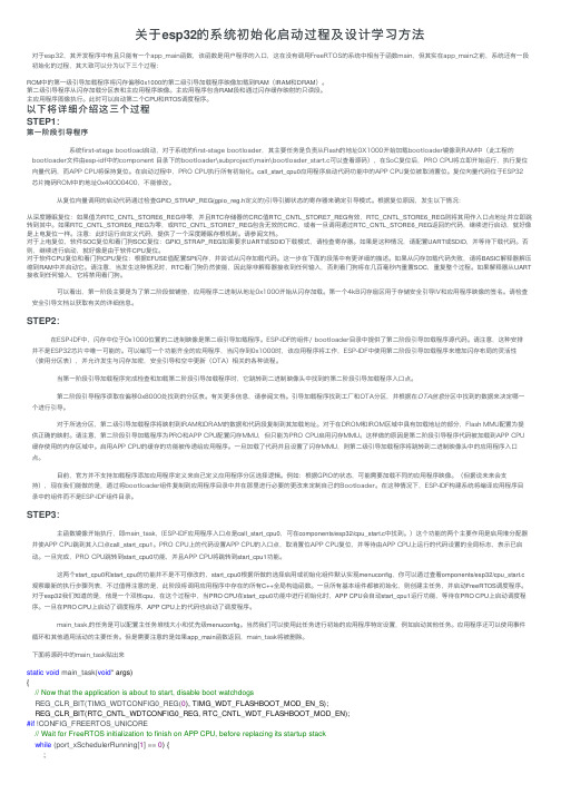
关于esp32的系统初始化启动过程及设计学习⽅法对于esp32,其开发程序中有且只能有⼀个app_main函数,该函数是⽤户程序的⼊⼝,这在没有调⽤FreeRTOS的系统中相当于函数main,但其实在app_main之前,系统还有⼀段初始化的过程,其⼤致可以分为以下三个过程:ROM中的第⼀级引导加载程序将闪存偏移0x1000的第⼆级引导加载程序映像加载到RAM(IRAM和DRAM)。
第⼆级引导程序从闪存加载分区表和主应⽤程序映像。
主应⽤程序包含RAM段和通过闪存缓存映射的只读段。
主应⽤程序图像执⾏。
此时可以启动第⼆个CPU和RTOS调度程序。
以下将详细介绍这三个过程STEP1:第⼀阶段引导程序 系统first-stage bootload启动,对于系统的first-stage bootloader,其主要任务是负责从Flash的地址0X1000开始加载bootloader镜像到RAM中(此⼯程的bootloader⽂件由esp-idf中的component ⽬录下的bootloader\subproject\main\bootloader_start.c可以查看源码),在SoC复位后,PRO CPU将⽴即开始运⾏,执⾏复位向量代码,⽽APP CPU将保持复位。
在启动过程中,PRO CPU执⾏所有初始化。
call_start_cpu0应⽤程序启动代码功能中的APP CPU复位被取消置位。
复位向量代码位于ESP32芯⽚掩码ROM中的地址0x40000400,不能修改。
从复位向量调⽤的启动代码通过检查GPIO_STRAP_REG(gpio_reg.h定义的)引导引脚状态的寄存器来确定引导模式。
根据复位原因,发⽣以下情况:从深度睡眠复位:如果值为RTC_CNTL_STORE6_REG⾮零,并且RTC存储器的CRC值RTC_CNTL_STORE7_REG有效,RTC_CNTL_STORE6_REG则将其⽤作⼊⼝点地址并⽴即跳转到其中。
ePSXe+图文设置教程

准备epsxe目前比较稳定的版本为1.60 下载epsxe 安装后桌面会生成图标也可打开资源管理器找到安行epsxe.exe安装后文件如下[attach]86908[/attach]让我们分别来看看几个常用的文件夹的作用。
最左边的是BIOS 文件夹,用于存放BIOS 文件。
ePS 的BIOS---Scph1001.bin 就要放到此文件夹下存放记忆卡的文件夹memcards ,epsxe000 是第一块记忆卡,epsxe001 是第二块Plugins 文件夹,用来存放各种插件,如:图像,声音,手柄,光驱。
凡是插件就解压缩到注意:由于插件都是*.dll的文件,平时是隐藏属性,你是看不到的,我为了让大家清楚才把属性改为你的文件夹下没有,改一下显示文件的属性看看吧开始双击那个手柄模样的可执行文件epsxe.exe[attach]86909[/attach]控制栏有5个菜单标签(File,Run,Config,Options,Cheat)FileRun CDROM:运行Ps游戏碟Run BIOS:运行Ps主机biosRun ISO:运行Ps碟的iso镜像文件Run PSX EXE:运行Ps碟EXE文件Chage Disc: 换盘Exit:退出RunContinue:继续运行之前被“Esc”中断的游戏Reset:重新启动Config (这部分最烦)Video:图象部分,选择适合自己显卡的插件,并进行一系列的设置Sound:声音部分,选择适合自己声卡的插件,并进行一系列的设置Cdrom:选个适合自己光驱的插件,设定好光驱所在的盘符(我是f:)Bios:随便选一个吧,我试试都差不多的MDEC:用来控制播放游戏中的动画Memory Card: 记录卡Game Pad: 设置游戏手柄OptionsSIO irq always enable:永远打开SIO中断。
(f4键)Country: 选择播放的制式(Autodetect PAL NTSC)CheatEdit Cheat Codes:编辑金手指代码**help帮助文件,没什么可说的设置篇第一次运行配置向导会弹出epsxe模拟器必须进行设置分视频声音等每一项必须选择一个插件比如说视频中就有好多插件geforce系列就应该选择openGL的那个插件你可以按着向导一步一步完成设置下面我们不按着向导详细讲解各项设置视频部分从菜单选取配置-视频如图[attach]86910[/attach]如果您的显示卡是geforce系列可以选Pete's OpenGL加速插件 1.56 具体情况可以看向导里面说击配置按钮(Pete's OpenGL加速插件已经升级到1.64) 如图[attach]86911[/attach]你可以用默认设置如果您的机器好可以选画面更靓否则可以选速度更快你可以把“启动时在屏幕上勾这样就可以在游戏中屏幕的左上角看到帧数应该使帧数保持在55帧以上最好是满帧60帧(或择不同的选项以达到更高的帧数把“特定游戏修正”打上勾单击画紫圈的按钮如下图[attach]86912[/attach]把“修复铁拳3过关暂停的问题”打上勾音频部分如图[attach]86913[/attach]选择ePSXe 内建驱动1.5.0. 如图设置光驱部分如图选择ePSXe 内建光驱驱动1.5.0.[attach]86914[/attach]单击配置选择你的光驱以下是bios 纪录卡手柄的设置[attach]86915[/attach][attach]86916[/attach][attach]86917[/attach]你可以选择我们提供的记忆卡文件请用第一个记忆卡选择epsxe第二个记忆卡好像不能用运行游戏把铁拳3的ps游戏光盘放入光驱选“Run CDROM”就行了单击-文件-运行光盘或单击-文件-运行镜像选定铁拳3的镜像文件比如tk3.iso或tk3.bin 就可[attach]86918[/attach]两分钟架设Kaillera服务器下载Kaillera 的服务器端程序,用写字板打开设置文件kaillerasrv.conf,然后按照里面的参数进行释穇译成中文,超级简单,一看就明白。
ESP8266新手入门调试教程指导含目录
ESP8266新手入门调试教程指导含目录目录:1.介绍2.准备工作3.环境配置4.连接硬件5.安装驱动程序6.编写代码7.编译和烧录8.调试与测试1.介绍:2.准备工作:在开始调试之前,你需要准备以下工具和材料:- ESP8266模块 (如NodeMCU)-一台计算机-USB数据线-杜邦线-LED灯3.环境配置:4.连接硬件:将ESP8266模块通过USB数据线连接到计算机的USB接口上。
确保连接稳定,没有松动或接触不良的问题。
5.安装驱动程序:大多数操作系统都会自动检测并安装ESP8266模块的驱动程序。
如果你的操作系统无法自动识别设备,请在官方网站上找到合适的驱动程序进行安装。
6.编写代码:打开Arduino IDE,在"文件"菜单中选择"新建",并将以下代码粘贴到新建的文件中:```c++#define LED_PIN 2 // 设置LED灯的引脚void setupinMode(LED_PIN, OUTPUT); // 将LED引脚设置为输出void loodigitalWrite(LED_PIN, HIGH); // 将LED引脚输出设为高电平,点亮LED灯delay(1000); // 延时1秒digitalWrite(LED_PIN, LOW); // 将LED引脚输出设为低电平,熄灭LED灯delay(1000); // 延时1秒```这段代码的作用是让ESP8266控制一个连接到引脚2的LED灯,每隔1秒钟进行一次闪烁。
7.编译和烧录:在Arduino IDE中,选择适合你的ESP8266板型和串口,点击"工具"菜单中的"板型"和"串口"进行设置。
然后点击工具栏上的"上传"按钮,将代码编译并烧录到ESP8266模块中。
8.调试与测试:完成烧录后,你应该可以看到LED灯开始闪烁。
espush开发板入门教程
ESPUSH蘑菇云开发板入门教程第一步,下载固件烧写程序大家拿到手上的开发板,实际上已经烧好的固件程序,但是为了大家更方便学习,最好也重新烧写一遍固件程序。
1、在蘑菇云的百度云空间中找到软件工具,双击进去,找到一键烧写软件。
根据自己的电脑配置,选择相应的软件。
2、打开一键烧写软件固件类型:选择ESPUSH专属固件串口:选择对应的串口。
(若无法找到串口,请确认是否安装好CH340的驱动,到蘑菇云的百度云空间,可以直接下载)(波特率已经默认为115200,如有用户此波特率无法使用,请联系我们,在我们的QQ群480288089里找群主,可提供多种波特率的软件)。
在平台上注册ID,输入ID合KEY后,点击开始,不要忘记硬件的设置。
3、将开发板上电,按下K3,电源指示灯L1亮起。
4、将拨码开关拨到GND。
5、按下复位键K2,对ESP8266进行复位处理。
(非常重要,不然烧写将会失败.)6、点击一键烧写软件的开始,就将固件烧写进开发板内。
看到再次开始的按钮就表示烧写成功。
可以正式开始测试了。
7、拨码开关拨回IO0,如若未拨回IO0,也可以正常使用,但是无法进行复位处理。
所以记住测试的时候要拨回IO0。
注意:在烧写过程中,板子的三色灯会变亮,属于正常情况。
8、从蘑菇云百度云平台中下载蘑菇云硬件测试软件,ComSoft.9、打开软件,选择好串口,波特率为115200。
点击连接设备,当显示“已连接”时,表示已经连接成功。
可以选择点击“AT命令”,“开灯”,“关灯”,在接收区数据显示处,可以看见命令的回复。
你发开灯命令时,可以看下开发板上的L3是否点亮和关闭。
ESPRIT 初级培训手册

如果您能选择“铣削刀具”,几何工具条将隐藏而铣削刀具指令将显示.所有在Smart Toolbar中激活的的工具条下次将始终显示在同样的位置上,您不需要重新寻找指令.
1-3
ESPRIT2011 总体功能介绍
使用ESPRIT
当您第一次打开ESPRIT或创建一个新文件 时,ESPRIT将提示您是以一个空白文件开始 还是以一个模板文件开始. 《空白文件》选项将打开一个ESPRIT缺省 的空白文件.模板文件包含用户自定义的元 素及设置信息.模板中能够包括常用的刀 具,机床设置,仿真设置等. 模板对话框的显示可由工具菜单的“选项” 对话框中的“Input”页面中的“显示模板对 话框”选项来进行控制.缺省情况下,模板对 话框显示. 作为新的用户,选择《空白文件》后单击“确定”.单击“取消”具有同样的效果. 更多关于如何创建及使用模板文件,请参考ESPRIT在线帮助. 文件管理 您一次只能打开一个ESPRIT文件且只能有一个ESPRIT程序在运行. 创建一个新文件 单击“新文件”来关闭当前文件并创建新文件.如果当前文件已经 有修改,ESPRIT将提示您在关闭文件之前是否保存相关修改. 打开一个已存在文件 单击“打开”来打开已有的ESPRIT文件(后缀名为.esp),以及 其他2D或3D的CAD文件,例如SolidWorks,Pro/E,stereolithography(STL),IGES,STEP等. 因为ESPRIT是基于Parasolid的内核,因此可以方便打开各种实体文件.
此课程包括
ESPRIT图形用户界面..................................................1-2 菜单................................................................1-3 缺省工具条..........................................................1-3 Smart Toolbar.......................................................1-3 使用ESPRIT..........................................................1-4 文件管理............................................................1-4 ESPRIT选项......................................................... 1-8 工具条..............................................................1-12 元素选择............................................................1-12 平移,缩放和旋转视图.................................................1-14 几何创建............................................................1-15 输入数值............................................................1-15 不带边界几何....................................................... 1-15 边界几何............................................................1-16 工作平面..............................1-16 特征................................................................1-17 特征类型............................................................1-17 特征创建............................................................1-18 编辑特征............................................................1-18 特征属性............................................................1-19 特征与工作平面关联..................................................1-19 练习:创建特征.......................................................1-19
实践操作说明:ESP路试与系统测试

ESP路试与系统测试:ESP路试检查ESP系统各个传感器的可靠性(侧向加速度传感器-G200,横摆率传感器-G202和制动压力传感器-G201,方向盘角度传感器-G85).每次ESP系统的电气元件拆下或更换后,必须进行路试.对ESP系统的路试一旦开始,就不能中止,必须全部进行完毕. 测试通过选择基本设定(04),显示组号03来进行.ABS与ASR/ESP灯点亮,故障01486(系统进行动态测试)存储在故障存储中.断开VAS5051起动发动机用力踏下制动踏板(压力大约为35 bar)直到ASR/ESP警报灯-K86熄灭退出(标定完成)操纵:进行时间大约5秒,速度在15与20km/h,半径在10到12米曲线的路试。
此时,ABS、EDS、ASR、ESP都不工作。
其它操作对ESP测试都没有影响。
测试评价:路试完成后,ABS与ASR/ESP灯熄灭,测试通过,系统正常。
如果ABS与ASR/ESP灯没有熄灭,读取故障存储,并排除故障。
如果路试中止,ABS与ASR/ESP灯依然点亮。
当进行系统测试,但没有启动ABS与ASR/ESP功能时,必须重新进行测试。
要注意交通法规。
方向盘转向角度传感器标定:需要条件:底盘的几何形状正常.如果转向角度传感器断电或车辆的电压值不正常时,传感器的标定就会丢失。
故障:01826转向角度传感器端子30电压供应就会存储在故障存储中。
测量数据块5中测量数据1显示-2.5。
通过短距离行驶,传感器会根据车轮转速信息重新开始初始化。
存储的故障01826仅为偶发故障,能够清除。
零位置补偿同样可以通过VAS5051的自诊断或测试程序手动进行而无需进行路试(参见诊断对象:转向角度传感器零位补偿)。
点火开关打开后,顺时针或逆时针转动方向盘至少10度,对转向角度传感器进行初始化.然后,必须将前轮置于垂直向前方向(公差+/-5度)。
如果方向盘不在规定的范围内,转向角度传感器标定错误。
通过08读测量数据块(测量数据块5的第一个值),调节方向盘在规定的范围内,检查前轮的垂直向前位置与方向盘的水平位置。
esp32教程

esp32教程中杏的ESP32教程ESP32是一款低功耗的WiFi和蓝牙双模模块,具备强大的处理能力和丰富的外设接口。
本教程将介绍ESP32的基本使用方法,适用于初学者入门以及对ESP32感兴趣的人群。
一、ESP32的基本介绍ESP32是由乐鑫科技开发的一款双核心微控制器,主频高达240MHz,内置WiFi和蓝牙模块,支持多种外设接口和传感器,广泛应用于物联网、智能家居等领域。
二、ESP32的开发环境搭建1. 安装Arduino IDE在官网下载Arduino IDE最新版本并安装,在“工具”菜单中选择“开发板”,然后选择“ESP32 Dev Module”。
2. 安装ESP32驱动程序在Windows设备管理器中找到ESP32开发板对应的端口号,然后在Arduino IDE中选择该端口号。
三、ESP32的GPIO控制1. 引脚模式设置使用pinMode(pin, mode)函数可以将指定引脚设置为输入或输出模式。
2. 数字信号输出使用digitalWrite(pin, value)函数可以向指定引脚输出低电平(0)或高电平(1)信号。
3. 数字信号输入使用digitalRead(pin)函数可以读取指定引脚的输入信号,返回值为LOW(低电平)或HIGH(高电平)。
四、ESP32的WiFi连接1. 设置WiFi参数使用WiFi.begin(ssid, password)函数可以连接到指定的WiFi网络,其中ssid是网络名称,password是密码。
2. 检查WiFi连接状态使用WiFi.status()函数可以获取当前WiFi连接的状态,返回值为WL_CONNECTED表示已连接。
五、ESP32的蓝牙控制1. 蓝牙初始化使用BluetoothSerial.begin()函数可以初始化蓝牙模块。
2. 发送数据使用BluetoothSerial.write()函数可以向蓝牙设备发送数据。
六、ESP32的传感器应用1. 温湿度传感器使用DHT库可以读取温湿度传感器的数据,并在串口上进行显示。
ESP8266新手入门调试指导(补全)教案资料

E S P8266新手入门调试指导(补全)ESP8266 ESP-01调试全过程–使用指导测试&编写&汇总by fairyhui 一接线注意:本系统是3.3V ! 请勿接5V !新版(全IO口引出版):此版本若想从FLASH启动进入AT系统,只需CH-PD引脚接VCC或接上拉(不接上拉的情况下,串口可能无数据),其余三个引脚可选择悬空或接VCC(但群里(@云海之梦)反映接VCC后导致无法正常启动)(GPIO0为高电平代表从FLASH启动,GPIO0为低电平代表进入系统升级状态,此时可以经过串口升级内部固件RST(GPIO16)可做外部硬件复位使用)测试系统不同,接线方法也选择多多,请各位根据自己的情况进行选择,推荐接法:在CH-PD和VCC之间焊接电阻后,将UTXD,GND,VCC,URXD连上USB-TTL(两者的TXD和RXD交叉接)即可进行测试旧版(AT指令版):该版本中间四根线悬空即可。
群里(@ZR(小R))反应:接线正确的情况下,连上USB转TTL,红灯蓝灯闪烁一下以后全灭,此现象为模块电流过大,超过了USB转TLL模块的承受范围。
解决办法:1. CH-PD换一个阻值更大的上拉电阻;2.换个承受电流大一点USB转TLL模块(群众们也可以自己改造)(@ZR(小R))反应:在供电不足的情况下,收到的响应为乱码。
请各位检查下供电电压是否足够。
二上电:正常工作验证本模块可以工作在三种模式:1. STA 2 .AP 3 .AP+STA,出厂设置为第三种上电后,蓝色灯微弱闪烁后熄灭,红灯长亮1. 搜索无线网络,可见ESP_XXXXXX已经处于列表中(后面的数字是MAC地址后几位)连接该网络以后,查看连接状态:手机搜索该网络,也可连接上:2.使用USR-TCP232-Test.exe进行测试:软件配置如下图:注意:(1)波特率一般在出厂情况下默认的是115200。
如果在115200情况下收到的是乱码可以试试其他波特率(旧版本的默认波特率可能是其他数值)。
ESP32-S3 ESP-SR 用户手册说明书

ESP32-S3ESP-SR用户手册Release master乐鑫信息科技2023年12月06日Table of contentsTable of contents i 1入门指南31.1概述 (3)1.2准备工作 (3)1.2.1必备硬件 (3)1.2.2必备软件 (3)1.3编译运行一个示例 (3)2AFE声学前端52.1AFE声学前端算法框架 (5)2.1.1概述 (5)2.1.2使用场景 (5)2.1.3选择AFE Handle (8)2.1.4输入音频 (8)2.1.5输出音频 (9)2.1.6使能唤醒词识别WakeNet (9)2.1.7使能回声消除算法AEC (9)2.1.8资源消耗 (10)2.2乐鑫麦克风设计指南 (10)2.2.1麦克风电器性能推荐 (10)2.2.2麦克风结构设计建议 (10)2.2.3麦克阵列设计建议 (10)2.2.4麦克风结构密封性建议 (10)2.2.5回声参考信号设计建议 (11)2.2.6麦克风阵列一致性验证 (11)3唤醒词133.1WakeNet唤醒词模型 (13)3.1.1概述 (13)3.1.2WakeNet的使用 (14)3.1.3资源消耗 (15)3.2乐鑫语音唤醒方案客户定制流程 (15)3.2.1唤醒词定制服务 (15)3.2.2硬件设计与测试服务 (16)4命令词174.1MultiNet命令词识别模型 (17)4.2命令词识别原理 (17)4.3命令词格式要求 (17)4.4自定义命令词方法 (18)4.4.1MultiNet6定义方法: (18)4.4.2MultiNet5定义方法: (18)4.4.3通过调用API修改 (19)4.5MultiNet的使用 (20)4.5.1MultiNet初始化 (21)4.5.2MultiNet运行 (21)4.5.3MultiNet识别结果 (21)4.6资源消耗 (22)5TTS语音合成模型235.1简介 (23)5.2简单示例 (23)5.3编程指南 (24)5.4资源消耗 (24)6模型加载256.1配置方法 (25)6.1.1Model Data Path (26)6.1.2使用AFE (26)6.1.3使用WakeNet (26)6.1.4使用MultiNet (26)6.2模型使用 (27)6.2.1模型数据存储在Flash SPIFFS (27)6.2.2模型数据存储在SD卡 (27)7性能测试结果297.1AFE (29)7.1.1资源消耗 (29)7.2WakeNet (29)7.2.1资源消耗 (29)7.2.2性能测试 (29)7.3MultiNet (30)7.3.1资源消耗 (30)7.3.2Word Error Rate性能测试 (30)7.3.3Speech Commands性能测试(空调控制场景) (30)7.4TTS (30)7.4.1资源消耗 (30)7.4.2性能测试 (31)8测试方法与测试报告338.1测试场景要求 (33)8.2测试案例设计 (33)8.3乐鑫测试与结果 (34)8.3.1唤醒率测试 (35)8.3.2语音识别率测试 (35)8.3.3误唤醒率测试 (35)8.3.4唤醒打断率测试 (35)8.3.5响应时间测试 (36)9术语表379.1通用术语 (37)9.2特别术语 (37)本文档仅包含针对ESP32-S3芯片的ESP-SR使用。
ESP宝来轿车电子稳定程序讲解

ESP宝来轿车电子稳定程序1 概述现代汽车技术发展的一个主要方向就是提高主动安全性以避免事故的发生,并充分发挥车辆的动力性能。
为提高汽车行驶的安全性能,宝来04年型汽车在原有装备基础上,又增加了电子稳定系统ESP。
ESP是英语Electronic Stability Program缩写,意为电子稳定程序,它是一个主动安全系统,是建立在其它牵引控制系统之上的一个非独立的系统。
通过有选择性的分缸制动及发动机管理系统干预,防止车辆滑移。
图1为宝来04款汽车制动系统各部件及其装配位置图。
(略2 ESP电控系统ESP电控系统由传感器、控制单元和执行元件三部分组成,如图2所示。
2.1 传感器ESP主要传感器包括方向盘转角传感器G85,侧向加速度传感器G200,横摆角速度传感器G202和制动压力传感器 G201。
(1)方向盘转角传感器G85安装位置:转向柱上,转向开关与方向盘之间,与安全气囊时钟弹簧集为一体。
作用:向带有EDL/TCS/ESP的ABS控制单元传递方向盘转角信号。
测量范围: -720度,4圈,测量精度:1.5度,分辨速度:1-2000度/秒失效影响:系统将不能识别车辆的预期行驶方向(驾驶员意愿),导致ESP不起作用。
自诊断:更换控制单元或传感器后,需重新标定零点。
电路连接:G85是ESP系统中唯一一个直接由CAN-BUS向控制单元传递信号的传感器。
打开点火开关后,方向盘被转动4.5度(相当于1.5cm,传感器进行初始化。
拆装注意事项:安装时,要保证G85在正中位置,观察孔内黄色标记可见。
(2)侧向加速度传感器G200安装位置:转向柱下方偏右侧,与横摆角速度传感器一体。
作用:确定侧向力失效影响:没有G200信号,无法识别车辆状态,ESP失效测量精度:1.2V/g,测量范围: -1.7g(加速度,信号:0-2.5V(3)横摆角速度传感器G202安装位置:转向柱下方偏右侧,与侧向加速度传感器一体。
作用:G202感知作用在车辆上的扭矩,识别车辆围绕垂直于地面轴线方向的旋转运动。
ESP8266新手入门调试指导要点
ESP8266新手入门调试指导要点1.了解ESP8266的基本知识:-了解ESP8266的硬件规格和引脚定义,以便正确连接和配置。
-熟悉ESP8266的AT指令集,这是通过串口与模块进行通信的主要方式。
-了解ESP8266的固件和固件升级的方法,确保使用最新版本的固件。
2.搭建调试环境:-准备一台带有串口功能的计算机,用于与ESP8266进行通信和查看调试输出。
-连接ESP8266模块到计算机的串口,使用USB转串口转接板。
-安装串口驱动程序,确保计算机能够正确识别串口设备。
3.测试串口通信:- 在计算机上打开串口终端程序(如TeraTerm、Putty等),设置正确的串口号、波特率等参数。
-向ESP8266发送AT指令,如"AT",并确认是否收到了正确的响应。
-测试一些基本的AT指令,如查询固件版本、查询模块状态等。
4.连接到Wi-Fi网络:-设置ESP8266连接到Wi-Fi网络的参数,包括SSID、密码等。
-使用AT指令将ESP8266连接到指定的Wi-Fi网络。
-确认ESP8266是否成功连接到指定的Wi-Fi网络,可以通过查询IP地址等方式进行验证。
5.进行网络通信:-使用AT指令设置ESP8266为TCP或UDP服务器或客户端模式。
-测试ESP8266的网络通信功能,如发送HTTP请求、接收HTTP响应等。
-理解和使用ESP8266的多连接功能,通过建立多个连接实现同时与多个设备通信。
6.开始编程:- 学习ESP8266的编程语言,如Arduino、MicroPython等。
-阅读并尝试运行一些示例代码,理解代码的用途和工作原理。
7.调试和故障排除:-根据调试输出或错误信息,确定可能出现问题的原因。
-使用调试工具或调试信息来检查代码的执行情况,查找潜在的错误。
-尝试不同的调试方法和技巧,如将调试信息打印到串口、使用调试器等。
8.学习和拓展:。
ESP用户手册

ESP培训手册编制:徐峰目录1.软件安装与快速启动向导 (2)这里以阅读器MINI作为介绍对象 (2)1.1S TEP1------检查硬件设备 (2)1.2S TEP2------连接系统 (2)1.3S TEP3------阅读器安装位置 (3)1.4S TEP4------安装ESP软件 (3)ESP是M ICROSCAN为所有阅读器安装程序与测试程序软件,并不是说它是一种接到指令立即执行的工具。
ESP 软件的目的是提供快速,简捷的方式建立和设定你的阅读器参数。
当你的阅读器连接上主机时,你就可以用ESP软件进行设定和阅读的控制。
(3)从M ICROSCAN CD安装ESP软件 (3)1.5S TEP5------阅读器模式选择 (4)1.6S TEP6------自动连接模式 (5)1.7S TEP7------标记的定位 (6)1.8S TEP8------校验参数的设置 (8)1.9S TEP9------阅读速率测试 (8)1.10S TEP10------用ESP软件设定阅读器的参数 (9)1.11S TEP11------用ESP软件对菜单进行修改与保存 (10)2,ESP软件的使用 (11)2.1启动ESP程序 (11)2.2连接硬件 (11)2.3阅读参数设定 (12)2.3.1通讯 (12)2.3.3条码类型设置 (14)2.3.5条码质量的设置 (15)2.4摄像参数设置 (16)2.5发送/保存命令 (19)2.5终端测试 (20)2.6自动连接 (20)2.7阅读器的模式转换 (20)1.软件安装与快速启动向导这里以阅读器MINI作为介绍对象1.1Step1------检查硬件设备警告:在给系统供电前必须保证各硬件已正确连接,总是保持未连接任何硬件时系统处于无电状态1.2 Step2------连接系统连接时采用串口RS-232协议1.3 Step3------阅读器安装位置阅读器安装位置的焦距大约在50mm~~150mm之间。
ESP32-C3 ESP-AT 用户指南说明书

ESP32-C3ESP-AT用户指南Release v2.3.0.0-esp32c3-595-g6118fc225a乐鑫信息科技2023年07月28日Table of contentsTable of contents i 1入门指南31.1ESP-AT是什么 (3)1.2硬件连接 (4)1.2.1硬件准备 (4)1.2.2ESP32-C3系列 (5)1.3下载指导 (5)1.3.1下载AT固件 (5)1.3.2烧录AT固件至设备 (6)1.3.3检查AT固件是否烧录成功 (9)2AT固件112.1发布的固件 (11)2.1.1ESP32-C3-MINI-1系列 (11)2.2AT固件简介 (12)2.3我该选哪种类型的固件? (12)2.3.1官方发布版固件(推荐) (12)2.3.2GitHub临时固件 (13)2.3.3修改参数的固件 (13)2.3.4自行编译的固件 (13)2.4获取固件后,接来下做什么? (13)3AT命令集153.1基础AT命令集 (15)3.1.1介绍 (16)3.1.2AT:测试AT启动 (16)3.1.3AT+RST:重启模块 (16)3.1.4AT+GMR:查看版本信息 (17)3.1.5AT+CMD:查询当前固件支持的所有命令及命令类型 (17)3.1.6AT+GSLP:进入Deep-sleep模式 (18)3.1.7ATE:开启或关闭AT回显功能 (18)3.1.8AT+RESTORE:恢复出厂设置 (19)3.1.9AT+SAVETRANSLINK:设置开机Wi-Fi/Bluetooth LE透传模式信息 (19)3.1.10AT+TRANSINTVL:设置透传模式模式下的数据发送间隔 (21)3.1.11AT+UART_CUR:设置UART当前临时配置,不保存到flash (22)3.1.12AT+UART_DEF:设置UART默认配置,保存到flash (23)3.1.13AT+SLEEP:设置睡眠模式 (24)3.1.14AT+SYSRAM:查询当前剩余堆空间和最小堆空间 (25)3.1.15AT+SYSMSG:查询/设置系统提示信息 (26)3.1.16AT+SYSMSGFILTER:启用或禁用系统消息过滤 (27)3.1.17AT+SYSMSGFILTERCFG:查询/配置系统消息的过滤器 (28)3.1.18AT+SYSFLASH:查询或读写flash用户分区 (31)3.1.19AT+SYSMFG:查询或读写manufacturing nvs用户分区 (32)3.1.20AT+RFPOWER:查询/设置RF TX Power (35)3.1.21说明 (36)3.1.22AT+SYSROLLBACK:回滚到以前的固件 (37)i3.1.23AT+SYSTIMESTAMP:查询/设置本地时间戳 (37)3.1.24AT+SYSLOG:启用或禁用AT错误代码提示 (38)3.1.25AT+SLEEPWKCFG:设置Light-sleep唤醒源和唤醒GPIO (39)3.1.26AT+SYSSTORE:设置参数存储模式 (40)3.1.27AT+SYSREG:读写寄存器 (41)3.1.28AT+SYSTEMP:读取芯片内部摄氏温度值 (42)3.2Wi-Fi AT命令集 (42)3.2.1介绍 (43)3.2.2AT+CWINIT:初始化/清理Wi-Fi驱动程序 (43)3.2.3AT+CWMODE:查询/设置Wi-Fi模式(Station/SoftAP/Station+SoftAP) (44)3.2.4AT+CWSTATE:查询Wi-Fi状态和Wi-Fi信息 (45)3.2.5AT+CWJAP:连接AP (45)3.2.6AT+CWRECONNCFG:查询/设置Wi-Fi重连配置 (48)3.2.7AT+CWLAPOPT:设置AT+CWLAP命令扫描结果的属性 (49)3.2.8AT+CWLAP:扫描当前可用的AP (50)3.2.9AT+CWQAP:断开与AP的连接 (51)3.2.10AT+CWSAP:配置ESP32-C3SoftAP参数 (51)3.2.11AT+CWLIF:查询连接到ESP32-C3SoftAP的station信息 (52)3.2.12AT+CWQIF:断开station与ESP32-C3SoftAP的连接 (53)3.2.13AT+CWDHCP:启用/禁用DHCP (53)3.2.14AT+CWDHCPS:查询/设置ESP32-C3SoftAP DHCP分配的IPv4地址范围 (55)3.2.15AT+CWAUTOCONN:上电是否自动连接AP (55)3.2.16AT+CWAPPROTO:查询/设置SoftAP模式下802.11b/g/n协议标准 (56)3.2.17AT+CWSTAPROTO:设置Station模式下802.11b/g/n协议标准 (57)3.2.18AT+CIPSTAMAC:查询/设置ESP32-C3Station的MAC地址 (57)3.2.19AT+CIPAPMAC:查询/设置ESP32-C3SoftAP的MAC地址 (58)3.2.20AT+CIPSTA:查询/设置ESP32-C3Station的IP地址 (59)3.2.21AT+CIPAP:查询/设置ESP32-C3SoftAP的IP地址 (60)3.2.22AT+CWSTARTSMART:开启SmartConfig (61)3.2.23AT+CWSTOPSMART:停止SmartConfig (62)3.2.24AT+WPS:设置WPS功能 (63)3.2.25AT+MDNS:设置mDNS功能 (64)3.2.26AT+CWJEAP:连接WPA2企业版AP (64)3.2.27AT+CWHOSTNAME:查询/设置ESP32-C3Station的主机名称 (66)3.2.28AT+CWCOUNTRY:查询/设置Wi-Fi国家代码 (67)3.3TCP/IP AT命令 (68)3.3.1介绍 (69)3.3.2AT+CIPV6:启用/禁用IPv6网络(IPv6) (69)3.3.3AT+CIPSTATE:查询TCP/UDP/SSL连接信息 (70)3.3.4AT+CIPSTATUS(弃用):查询TCP/UDP/SSL连接状态和信息 (70)3.3.5AT+CIPDOMAIN:域名解析 (71)3.3.6AT+CIPSTART:建立TCP连接、UDP传输或SSL连接 (72)3.3.7AT+CIPSTARTEX:建立自动分配ID的TCP连接、UDP传输或SSL连接 (75)3.3.8[仅适用数据模式]+++:退出数据模式 (75)3.3.9AT+CIPSEND:在普通传输模式或Wi-Fi透传模式下发送数据 (76)3.3.10AT+CIPSENDL:在普通传输模式下并行发送长数据 (77)3.3.11AT+CIPSENDLCFG:设置AT+CIPSENDL命令的属性 (78)3.3.12AT+CIPSENDEX:在普通传输模式下采用扩展的方式发送数据 (79)3.3.13AT+CIPCLOSE:关闭TCP/UDP/SSL连接 (80)3.3.14AT+CIFSR:查询本地IP地址和MAC地址 (80)3.3.15AT+CIPMUX:启用/禁用多连接模式 (81)3.3.16AT+CIPSERVER:建立/关闭TCP或SSL服务器 (82)3.3.17AT+CIPSERVERMAXCONN:查询/设置服务器允许建立的最大连接数 (83)3.3.18AT+CIPMODE:查询/设置传输模式 (84)3.3.19AT+CIPSTO:查询/设置本地TCP/SSL服务器超时时间 (85)3.3.20AT+CIPSNTPCFG:查询/设置时区和SNTP服务器 (86)3.3.21AT+CIPSNTPTIME:查询SNTP时间 (87)3.3.22AT+CIPSNTPINTV:查询/设置SNTP时间同步的间隔 (88)ii3.3.23AT+CIPFWVER:查询服务器已有的AT固件版本 (89)3.3.24AT+CIUPDATE:通过Wi-Fi升级固件 (89)3.3.25AT+CIPDINFO:设置+IPD消息详情 (91)3.3.26AT+CIPSSLCCONF:查询/设置SSL客户端配置 (92)3.3.27AT+CIPSSLCCN:查询/设置SSL客户端的公用名(common name) (93)3.3.28AT+CIPSSLCSNI:查询/设置SSL客户端的SNI (94)3.3.29AT+CIPSSLCALPN:查询/设置SSL客户端ALPN (94)3.3.30AT+CIPSSLCPSK:查询/设置SSL客户端的PSK (95)3.3.31AT+CIPRECONNINTV:查询/设置Wi-Fi透传模式下的TCP/UDP/SSL重连间隔.963.3.32AT+CIPRECVMODE:查询/设置套接字接收模式 (97)3.3.33AT+CIPRECVDATA:获取被动接收模式下的套接字数据 (98)3.3.34AT+CIPRECVLEN:查询被动接收模式下套接字数据的长度 (98)3.3.35AT+PING:ping对端主机 (99)3.3.36AT+CIPDNS:查询/设置DNS服务器信息 (100)3.3.37AT+CIPTCPOPT:查询/设置套接字选项 (101)3.4Bluetooth®Low Energy AT命令集 (102)3.4.1介绍 (103)3.4.2AT+BLEINIT:Bluetooth LE初始化 (104)3.4.3AT+BLEADDR:设置Bluetooth LE设备地址 (105)3.4.4AT+BLENAME:查询/设置Bluetooth LE设备名称 (106)3.4.5AT+BLESCANPARAM:查询/设置Bluetooth LE扫描参数 (107)3.4.6AT+BLESCAN:使能Bluetooth LE扫描 (108)3.4.7AT+BLESCANRSPDATA:设置Bluetooth LE扫描响应 (109)3.4.8AT+BLEADVPARAM:查询/设置Bluetooth LE广播参数 (109)3.4.9AT+BLEADVDATA:设置Bluetooth LE广播数据 (111)3.4.10AT+BLEADVDATAEX:自动设置Bluetooth LE广播数据 (112)3.4.11AT+BLEADVSTART:开始Bluetooth LE广播 (113)3.4.12AT+BLEADVSTOP:停止Bluetooth LE广播 (113)3.4.13AT+BLECONN:建立Bluetooth LE连接 (114)3.4.14AT+BLECONNPARAM:查询/更新Bluetooth LE连接参数 (115)3.4.15AT+BLEDISCONN:断开Bluetooth LE连接 (116)3.4.16AT+BLEDATALEN:设置Bluetooth LE数据包长度 (117)3.4.17AT+BLECFGMTU:设置Bluetooth LE MTU长度 (117)3.4.18AT+BLEGATTSSRVCRE:GATTS创建服务 (118)3.4.19AT+BLEGATTSSRVSTART:GATTS开启服务 (119)3.4.20AT+BLEGATTSSRVSTOP:GATTS停止服务 (120)3.4.21AT+BLEGATTSSRV:GATTS发现服务 (120)3.4.22AT+BLEGATTSCHAR:GATTS发现服务特征 (121)3.4.23AT+BLEGATTSNTFY:服务器notify服务特征值给客户端 (122)3.4.24AT+BLEGATTSIND:服务器indicate服务特征值给客户端 (122)3.4.25AT+BLEGATTSSETATTR:GATTS设置服务特征值 (123)3.4.26AT+BLEGATTCPRIMSRV:GATTC发现基本服务 (124)3.4.27AT+BLEGATTCINCLSRV:GATTC发现包含的服务 (125)3.4.28AT+BLEGATTCCHAR:GATTC发现服务特征 (125)3.4.29AT+BLEGATTCRD:GATTC读取服务特征值 (126)3.4.30AT+BLEGATTCWR:GATTC写服务特征值 (127)3.4.31AT+BLESPPCFG:查询/设置Bluetooth LE SPP参数 (128)3.4.32AT+BLESPP:进入Bluetooth LE SPP模式 (129)3.4.33AT+BLESECPARAM:查询/设置Bluetooth LE加密参数 (130)3.4.34AT+BLEENC:发起Bluetooth LE加密请求 (131)3.4.35AT+BLEENCRSP:回复对端设备发起的配对请求 (132)3.4.36AT+BLEKEYREPLY:给对方设备回复密钥 (133)3.4.37AT+BLECONFREPLY:给对方设备回复确认结果(传统连接阶段) (133)3.4.38AT+BLEENCDEV:查询绑定的Bluetooth LE加密设备列表 (134)3.4.39AT+BLEENCCLEAR:清除Bluetooth LE加密设备列表 (134)3.4.40AT+BLESETKEY:设置Bluetooth LE静态配对密钥 (135)3.4.41AT+BLEHIDINIT:Bluetooth LE HID协议初始化 (136)3.4.42AT+BLEHIDKB:发送Bluetooth LE HID键盘信息 (137)iii3.4.43AT+BLEHIDMUS:发送Bluetooth LE HID鼠标信息 (137)3.4.44AT+BLEHIDCONSUMER:发送Bluetooth LE HID consumer信息 (138)3.4.45AT+BLUFI:开启或关闭BluFi (139)3.4.46AT+BLUFINAME:查询/设置BluFi设备名称 (140)3.4.47AT+BLUFISEND:发送BluFi用户自定义数据 (140)3.4.48AT+BLEPERIODICDATA:设置Bluetooth LE周期性广播数据 (141)3.4.49AT+BLEPERIODICSTART:开启周期性广播 (142)3.4.50AT+BLEPERIODICSTOP:停止周期性广播同步 (142)3.4.51AT+BLESYNCSTART:开启同步周期性广播 (143)3.4.52AT+BLESYNCSTOP:停止周期性广播同步 (143)3.4.53AT+BLEREADPHY:查询当前连接使用的PHY (144)3.4.54AT+BLESETPHY:设置当前连接的PHY (144)3.5MQTT AT命令集 (145)3.5.1介绍 (145)3.5.2AT+MQTTUSERCFG:设置MQTT用户属性 (146)3.5.3AT+MQTTLONGCLIENTID:设置MQTT客户端ID (146)3.5.4AT+MQTTLONGUSERNAME:设置MQTT登陆用户名 (147)3.5.5AT+MQTTLONGPASSWORD:设置MQTT登陆密码 (148)3.5.6AT+MQTTCONNCFG:设置MQTT连接属性 (148)3.5.7AT+MQTTALPN:设置MQTT应用层协议协商(ALPN) (149)3.5.8AT+MQTTCONN:连接MQTT Broker (150)3.5.9AT+MQTTPUB:发布MQTT消息(字符串) (151)3.5.10AT+MQTTPUBRAW:发布长MQTT消息 (151)3.5.11AT+MQTTSUB:订阅MQTT Topic (152)3.5.12AT+MQTTUNSUB:取消订阅MQTT Topic (153)3.5.13AT+MQTTCLEAN:断开MQTT连接 (153)3.5.14MQTT AT错误码 (154)3.5.15MQTT AT说明 (155)3.6HTTP AT命令集 (156)3.6.1介绍 (156)3.6.2AT+HTTPCLIENT:发送HTTP客户端请求 (156)3.6.3AT+HTTPGETSIZE:获取HTTP资源大小 (157)3.6.4AT+HTTPCGET:获取HTTP资源 (158)3.6.5AT+HTTPCPOST:Post指定长度的HTTP数据 (158)3.6.6AT+HTTPCPUT:Put指定长度的HTTP数据 (159)3.6.7AT+HTTPURLCFG:设置/获取长的HTTP URL (160)3.6.8AT+HTTPCHEAD:设置/查询HTTP请求头 (160)3.6.9HTTP AT错误码 (162)3.7文件系统AT命令集 (162)3.7.1介绍 (162)3.7.2AT+FS:文件系统操作 (163)3.7.3AT+FSMOUNT:挂载/卸载FS文件系统 (163)3.8WebSocket AT命令集 (164)3.8.1介绍 (164)3.8.2AT+WSCFG:配置WebSocket参数 (164)3.8.3AT+WSOPEN:查询/打开一个WebSocket连接 (165)3.8.4AT+WSSEND:向WebSocket连接发送数据 (166)3.8.5AT+WSCLOSE:关闭WebSocket连接 (167)3.9信令测试AT命令 (167)3.9.1介绍 (167)3.9.2AT+FACTPLCP:发送长PLCP或短PLCP (168)3.10驱动AT命令 (168)3.10.1介绍 (168)3.10.2AT+DRVADC:读取ADC通道值 (168)3.10.3AT+DRVPWMINIT:初始化PWM驱动器 (169)3.10.4AT+DRVPWMDUTY:设置PWM占空比 (170)3.10.5AT+DRVPWMFADE:设置PWM渐变 (171)3.10.6AT+DRVI2CINIT:初始化I2C主机驱动 (171)iv3.10.7AT+DRVI2CRD:读取I2C数据 (172)3.10.8AT+DRVI2CWRDATA:写入I2C数据 (172)3.10.9AT+DRVI2CWRBYTES:写入不超过4字节的I2C数据 (173)3.10.10AT+DRVSPICONFGPIO:配置SPI GPIO (174)3.10.11AT+DRVSPIINIT:初始化SPI主机驱动 (174)3.10.12AT+DRVSPIRD:读取SPI数据 (175)3.10.13AT+DRVSPIWR:写入SPI数据 (176)3.11Web服务器AT命令 (176)3.11.1介绍 (177)3.11.2AT+WEBSERVER:启用/禁用通过Web服务器配置Wi-Fi连接 (177)3.12用户AT命令 (178)3.12.1介绍 (178)3.12.2AT+USERRAM:操作用户的空闲RAM (178)3.12.3AT+USEROTA:根据指定URL升级固件 (179)3.12.4AT+USERWKMCUCFG:设置AT唤醒MCU的配置 (180)3.12.5AT+USERMCUSLEEP:MCU指示自己睡眠状态 (182)3.12.6AT+USERDOCS:查询固件对应的用户文档链接 (182)3.13AT命令分类 (183)3.14参数信息保存在flash中的AT命令 (184)3.15AT消息 (184)4AT命令示例1874.1AT响应消息格式控制示例 (187)4.1.1启用系统消息过滤,实现HTTP透传下载功能 (187)4.2TCP-IP AT示例 (189)4.2.1ESP32-C3设备作为TCP客户端建立单连接 (189)4.2.2ESP32-C3设备作为TCP服务器建立多连接 (191)4.2.3远端IP地址和端口固定的UDP通信 (193)4.2.4远端IP地址和端口可变的UDP通信 (194)4.2.5ESP32-C3设备作为SSL客户端建立单连接 (196)4.2.6ESP32-C3设备作为SSL服务器建立多连接 (198)4.2.7ESP32-C3设备作为SSL客户端建立双向认证单连接 (200)4.2.8ESP32-C3设备作为SSL服务器建立双向认证多连接 (202)4.2.9ESP32-C3设备作为TCP客户端,建立单连接,实现UART Wi-Fi透传 (204)4.2.10ESP32-C3设备作为TCP服务器,实现UART Wi-Fi透传 (205)4.2.11ESP32-C3设备作为softAP在UDP传输中实现UART Wi-Fi透传 (207)4.2.12ESP32-C3设备获取被动接收模式下的套接字数据 (209)4.3Bluetooth LE AT示例 (210)4.3.1简介 (211)4.3.2Bluetooth LE客户端读写服务特征值 (212)4.3.3Bluetooth LE服务端读写服务特征值 (215)4.3.4Bluetooth LE连接加密 (220)4.3.5两个ESP32-C3开发板之间建立SPP连接,以及在UART-Bluetooth LE透传模式下传输数据 (224)4.3.6ESP32-C3与手机建立SPP连接,以及在UART-Bluetooth LE透传模式下传输数据2294.3.7ESP32-C3和手机之间建立Bluetooth LE连接并配对 (231)4.4MQTT AT示例 (233)4.4.1基于TCP的MQTT连接(需要本地创建MQTT代理)(适用于数据量少) (233)4.4.2基于TCP的MQTT连接(需要本地创建MQTT代理)(适用于数据量多) (234)4.4.3基于TLS的MQTT连接(需要本地创建MQTT代理) (236)4.4.4基于WSS的MQTT连接 (238)4.5MQTT AT连接云示例 (239)4.5.1从AWS IoT获取证书以及endpoint (239)4.5.2使用MQTT AT命令基于双向认证连接AWS IoT (240)4.6Web Server AT示例 (244)4.6.1使用浏览器进行Wi-Fi配网 (244)4.6.2使用浏览器进行OTA固件升级 (250)4.6.3使用微信小程序进行Wi-Fi配网 (256)v4.6.4使用微信小程序进行OTA固件升级 (265)4.6.5ESP32-C3使用Captive Portal功能 (266)4.7HTTP AT示例 (266)4.7.1HTTP客户端HEAD请求方法 (267)4.7.2HTTP客户端GET请求方法 (268)4.7.3HTTP客户端POST请求方法(适用于POST少量数据) (269)4.7.4HTTP客户端POST请求方法(推荐方式) (270)4.7.5HTTP客户端PUT请求方法(适用于无数据情况) (272)4.7.6HTTP客户端PUT请求方法(推荐方式) (273)4.7.7HTTP客户端DELETE请求方法 (275)4.8Sleep AT示例 (276)4.8.1简介 (276)4.8.2在Wi-Fi模式下设置为Modem-sleep模式 (277)4.8.3在Wi-Fi模式下设置为Light-sleep模式 (278)4.8.4在蓝牙广播态下设置为Modem-sleep模式 (278)4.8.5在蓝牙连接态下设置为Modem-sleep模式 (279)4.8.6在蓝牙广播态下设置为Light-sleep模式 (280)4.8.7在蓝牙连接态下设置为Light-sleep模式 (281)4.8.8设置为Deep-sleep模式 (282)5如何编译和开发自己的AT工程2855.1本地编译ESP-AT工程 (285)5.1.1详细步骤 (285)5.1.2第一步:ESP-IDF快速入门 (285)5.1.3第二步:获取ESP-AT (286)5.1.4第三步:安装环境 (286)5.1.5第四步:连接设备 (286)5.1.6第五步:配置工程 (287)5.1.7第六步:编译工程 (287)5.1.8第七步:烧录到设备 (287)5.1.9build.py进阶用法 (288)5.2网页编译ESP-AT工程 (288)5.2.1详细步骤 (288)5.2.2第一步:登录您的GitHub账号 (288)5.2.3第二步:Fork ESP-AT工程 (288)5.2.4第三步:开启GitHub Actions功能 (290)5.2.5第四步:配置编译ESP-AT工程所需的密钥 (290)5.2.6第五步:使用github.dev编辑器修改和提交代码 (296)5.2.7第六步:GitHub Actions编译AT固件 (299)5.3如何设置AT端口管脚 (301)5.3.1ESP32-C3系列 (301)5.4添加自定义AT命令 (302)5.4.1定义AT命令 (302)5.4.2注册AT命令 (304)5.4.3尝试一下吧 (304)5.4.4定义返回消息 (305)5.4.5获取命令参数 (305)5.4.6省略命令参数 (305)5.4.7阻塞命令的执行 (308)5.4.8从AT命令端口获取输入的数据 (309)5.5如何提高ESP-AT吞吐性能 (312)5.5.1[简单]快速配置 (312)5.5.2[推荐]熟悉数据流、针对性地配置 (313)5.6如何更新mfg_nvs分区 (315)5.6.1mfg_nvs分区介绍 (316)5.6.2生成mfg_nvs.bin (316)5.6.3下载mfg_nvs.bin (316)5.7如何更新出厂参数 (316)vi5.7.1出厂参数配置介绍 (317)5.7.2生成mfg_nvs.bin文件 (317)5.7.3下载mfg_nvs.bin文件 (317)5.8如何更新PKI配置 (317)5.8.1PKI配置介绍 (318)5.8.2生成mfg_nvs.bin文件 (318)5.8.3下载mfg_nvs.bin文件 (318)5.9如何自定义低功耗蓝牙服务 (318)5.9.1低功耗蓝牙服务源文件介绍 (319)5.9.2编译时自定义低功耗蓝牙服务 (320)5.10如何自定义分区 (321)5.10.1修改at_customize.csv (322)5.10.2生成at_customize.bin (322)5.10.3烧录at_customize.bin至ESP32-C3设备 (322)5.10.4示例 (323)5.11如何增加一个新的模组支持 (323)5.11.1在factory_param_data.csv添加模组信息 (325)5.11.2修改esp_at_module_info结构体 (325)5.11.3配置模组文件 (326)5.12SPI AT指南 (326)5.12.1简介 (326)5.12.2使用SPI AT (327)5.12.3SPI AT速率 (330)5.13如何实现OTA升级 (330)5.13.1OTA命令对比及应用场景 (331)5.13.2使用ESP-AT OTA命令执行OTA升级 (332)5.14如何更新ESP-IDF版本 (335)5.15ESP-AT固件差异 (338)5.15.1ESP32-C3系列 (338)5.16如何从GitHub下载最新临时版本AT固件 (340)5.17at.py工具 (342)5.17.1详细步骤 (345)5.17.2第一步:Python安装 (345)5.17.3第二步:at.py下载 (345)5.17.4第三步:at.py用法说明 (346)5.17.5第四步:at.py修改固件中的配置示例 (346)5.17.6第五步:固件烧录 (348)5.18AT API Reference (348)5.18.1Header File (348)5.18.2Functions (349)5.18.3Structures (353)5.18.4Macros (355)5.18.5Type Definitions (356)5.18.6Enumerations (356)5.18.7Header File (358)5.18.8Functions (358)5.18.9Macros (359)5.18.10Enumerations (359)6第三方定制化AT命令和固件3616.1RainMaker AT命令和固件 (361)6.1.1RainMaker AT命令集 (361)6.1.2RainMaker AT示例 (375)6.1.3RainMaker AT OTA指南 (389)6.1.4Index of Abbreviations (391)6.1.5RainMaker AT消息 (392)7AT FAQ393vii7.1AT固件 (394)7.1.1我的模组没有官方发布的固件,如何获取适用的固件? (394)7.1.2如何获取AT固件源码? (394)7.1.3官网上放置的AT固件如何下载? (394)7.1.4如何整合ESP-AT编译出来的所有bin文件? (394)7.1.5模组出厂AT固件是否支持流控? (394)7.2AT命令与响应 (394)7.2.1AT提示busy是什么原因? (394)7.2.2AT固件,上电后发送第一个命令总是会返回下面的信息,为什么? (394)7.2.3在不同模组上的默认AT固件支持哪些命令,以及哪些命令从哪个版本开始支持?3957.2.4主MCU给ESP32-C3设备发AT命令无返回,是什么原因? (395)7.2.5ESP-AT命令是否支持ESP-WIFI-MESH? (395)7.2.6AT是否支持websocket命令? (395)7.2.7是否有AT命令连接阿里云以及腾讯云示例? (395)7.2.8AT命令是否可以设置低功耗蓝牙发射功率? (395)7.2.9如何支持那些默认固件不支持但可以在配置和编译ESP-AT工程后支持的命令?.3957.2.10AT命令中特殊字符如何处理? (395)7.2.11AT命令中串口波特率是否可以修改?(默认:115200) (396)7.2.12ESP32-C3使用AT指令进入透传模式,如果连接的热点断开,ESP32-C3能否给出相应的提示信息? (396)7.2.13低功耗蓝牙客户端如何使能notify和indicate功能? (396)7.3硬件 (396)7.3.1在不同模组上的AT固件要求芯片flash多大? (396)7.3.2AT固件如何查看error log? (396)7.3.3AT在ESP32-C3模组上的UART1通信管脚与ESP32-C3模组的datasheet默认UART1管脚不一致? (397)7.4性能 (397)7.4.1AT Wi-Fi连接耗时多少? (397)7.4.2ESP-AT固件中TCP发送窗口大小是否可以修改? (397)7.4.3ESP32-C3AT吞吐量如何测试及优化? (397)7.5其他 (397)7.5.1乐鑫芯片可以通过哪些接口来传输AT命令? (397)7.5.2ESP32-C3AT如何指定TLS协议版本? (397)7.5.3AT固件如何修改TCP连接数? (397)7.5.4ESP32-C3AT支持PPP吗? (398)7.5.5AT如何使能调试日志? (398)8Index of Abbreviations399 9关于ESP-AT405索引407索引407viiiTable of contents这里是乐鑫ESP-AT开发框架的文档中心。
ESP8266新手入门调试教程指导含目录
ESP8266新手入门调试教程指导含目录目录一、ESP8266介绍二、ESP8266的硬件连接三、ESP8266的固件烧录四、ESP8266的AT指令调试五、ESP8266的Web服务器搭建六、ESP8266的WiFi控制七、ESP8266的MQTT通信八、ESP8266的OTA升级九、ESP8266的Arduino开发十、ESP8266的常见问题与解决方法一、ESP8266介绍ESP8266是一款低成本、低功耗、Wi-Fi无线模块,由乐鑫科技推出,可以作为独立的嵌入式应用处理器,也可以通过它与其他MCU进行串口通信。
它基于SoC(System on Chip)架构,内置TCP/IP协议栈,支持STA/AP/STA+AP三种工作模式。
二、ESP8266的硬件连接ESP8266一般有多种引脚型号,具体的引脚功能可参考相应的硬件文档。
一般情况下,你需要将ESP8266的VCC引脚连接到3.3V电源,GND引脚连接到地,还需要连接一个串口转接板的TXD引脚到ESP8266的RXD 引脚,以及一个串口转接板的RXD引脚到ESP8266的TXD引脚。
三、ESP8266的固件烧录ESP8266的固件烧录可以采用多种方法,其中比较常用的有通过串口烧录和通过OTA(Over The Air)无线升级烧录。
通过串口烧录的方法需要先准备好一个串口转接板,并将ESP8266与串口转接板连接好,然后通过一个烧录工具将固件烧录进ESP8266、通过OTA烧录的方法则需要先将固件上传到ESP8266的Web服务器上,然后在ESP8266上执行相应的指令进行固件升级。
四、ESP8266的AT指令调试AT指令是一种通信协议,可用于与ESP8266进行交互,从而控制ESP8266的各种功能。
通过串口连接ESP8266后,我们可以通过串口通信软件发送AT指令给ESP8266,并查看ESP8266的返回结果来调试它的各项功能。
常用的AT指令有AT+GMR(查看固件版本)、AT+CWMODE(设置工作模式)、AT+CWJAP(连接WiFi网络)等。
雨鸟 ESP-ME3控制器 高级用户手册说明书
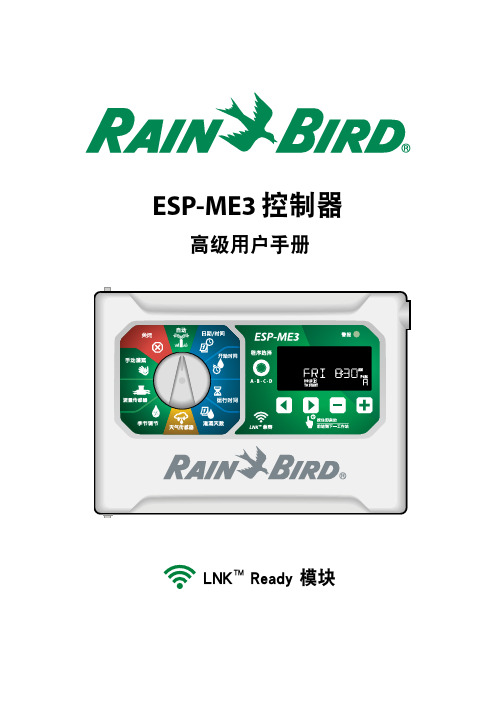
ESP-ME3控制器高级用户手册LNK TM Ready 模块ESP-ME3 控制器高级用户手册安全信息符号 & 用户操作a数字定义了用户操作控制器时所需要遵守的一些列步骤。
附注:提示了用户与控制器功能、安装或维护相关的重要操作说明。
重复:表明了如需进行下一步操作,或是完成流程,需要重复上一步骤或行为。
简介 ......................................................3欢迎使用雨鸟................................................................3智慧用水® ..................................................................3ESP-ME3 控制器性能 .................................................3启用 WiFi ...................................................................3安装 ......................................................4安装控制器....................................................................4连接阀门 ....................................................................4连接主阀(可选) ...................................................4连接泵启动继电器(可选)...................................5连接流量传感器(可选).......................................5连接天气传感器(可选).......................................6站点扩展模块................................................................7安装模块 ....................................................................7站点编号 ....................................................................7完成控制器安装 ...........................................................7正常操作 ...............................................8控制与性能....................................................................8自动.............................................................................8关闭.............................................................................8显示屏指示灯................................................................9基础编程 ...............................................91. 设置日期和时间.......................................................92. 设置灌溉开始时间...................................................93. 设置站点运行时间...................................................94. 设置灌溉日 .............................................................10一周自定义日..........................................................10基于程序的计划 .........................................................10常见编程错误..........................................................10手动灌溉选项 ......................................11测试所有站点..............................................................11运行一个站点..............................................................11运行一个程序..............................................................11高级编程 .............................................12奇数或偶数日历日 .....................................................12循环日 ..........................................................................12季节调节 ......................................................................12延迟灌溉 ......................................................................12永久日期关闭..............................................................13特殊性能 .............................................13选项 ...................................................14重置按钮 ......................................................................14远程附件 ......................................................................14分离编程 ......................................................................14电源寿命 . (14)附录 ....................................................15故障排除 ......................................................................15错误检测 ..................................................................15编程错误(LED 闪烁) ........................................15电气错误(LED 指示灯不闪烁)........................15流量警报 ..................................................................15灌溉问题 ..................................................................16电气问题(LED 常亮) ........................................16证书 ..............................................................................17安全信息 .. (17)LNK TM WiFi 模块(单独出售)启用 WiFi通过 LNK TM WiFi 模块,用户可以用 Apple ® iOS ® 或 Android TM 兼容智能设备远程连接雨鸟 ESP-ME3 控制器。
eSOM9261 WinCE6.0简易入门手册

深圳市盈安信科技有限公司w w w .e a c -s y s t e m s .c o m 电邮:i n f o @e a c -s y s t e m s .c o m 传真:0086-755-82523175转819e S O M /9261类别内容关键词 A T 91S A M 9261S 、W i n C E 6.0操作系统 摘要讲解e S O M /9261、 W i n C E 6.0系统编译、系统组件介绍、内核烧录、应用程序仿真等内容修订历史:版本 日期 原因V1.002010-7-20创建文档V1.002010-8-24修改完善S D卡烧写系统和U盘升级系统的内容目 录前 言 (4)一.W i n C E6.0系统概述 (5)§1.1V S2005与W i n C E6.0的关系 (5)§1.2W i n C E6.0系统的安装 (5)1.2.1W i n C E6.0系统安装步骤 (5)§1.3e S O M/9261W i n C E6.0系统运行原理 (7)1.3.1e S O M/9261W i n C E6.0非M u l t i-b i n格式系统从N a n d启动原理 (8)1.3.2e S O M/9261W i n C E6.0M u l t i-b i n系统从N a n d启动原理 (9)§1.4e S O M/9261W i n C E6.0系统升级 (9)1.4.1E N K.b i n文件的制作 (10)1.4.2自动升级 (10)1.4.3强制升级 (12)二.e S O M/9261E B O O T菜单介绍 (13)§2.1E B O O T菜单进入 (13)§2.2E B O O T菜单命令介绍 (13)三.e S O M/9261W i n C E6.0系统内核定制 (17)§3.1e S O M/9261W i n C E6.0B S P安装 (17)§3.2e S O M/9261W i n C E6.0B S P的组成部分 (17)§3.3e S O M/9261W i n C E系统组件介绍 (18)3.3.1打开已有的W i n C E6.0工程 (18)3.3.2e S O M/9261W i n C E系统第三方驱动组件(T h i r d P a r t y) (20)3.3.3e S O M/9261W i n C E系统公共组件 (22)§3.4e S O M/9261W i n C E系统编译 (23)3.4.1e S O M/9261V S2005环境介绍 (23)3.4.2e S O M/9261W i n C E系统编译 (25)四.e S O M/9261L o g o制作 (27)五.e S O M/9261W i n C E6.0内核烧录 (28)§5.1准备工作 (28)5.1.1超级终端工具 (28)§5.2用T F卡烧录W i n C E6.0系统 (29)§5.3用S A M-B A软件烧录W i n C E6.0系统 (31)5.3.1S A M-B A烧写E B O O T级内核 (32)5.3.2E S H E L软件下载N K.b i n (33)六.e S O M/9261W i n C E6.0应用程序仿真调试 (39)§6.1新建应用程序 (39)6.1.1e S O M/9261S D K安装 (39)6.1.2e S O M/9261系统A P I介绍 (39)6.1.3新建应用程序 (39)§6.2应用程序仿真 (44)§6.3使用V i s u a l S t u d i o2005的R e m o t e t o o l s (48)免责声明 (51)前 言文章用到的术语开发平台:指安装有W i n d o w s X P操作系统,M i c r o s o f t V i s u a l S t u d i o2005和W i n d o w s E m b e d d e d C E 6.0开发环境的X86平台P C机,该P C机需要有一个串口和一个U S B接口。
ESP优选新手入门调试指导补全

E S P8266E S P-01调试全过程–使用指导测试&编写&汇总b y f a i r y h u i一接线注意:本系统是3.3V!请勿接5V!新版(全IO口引出版):此版本若想从FLASH启动进入AT系统,只需CH-PD引脚接VCC或接上拉(不接上拉的情况下,串口可能无数据),其余三个引脚可选择悬空或接VCC(但群里(@云海之梦)反映接VCC后导致无法正常启动)(GPIO0为高电平代表从FLASH启动,GPIO0为低电平代表进入系统升级状态,此时可以经过串口升级内部固件RST(GPIO16)可做外部硬件复位使用)测试系统不同,接线方法也选择多多,请各位根据自己的情况进行选择,推荐接法:在CH-PD和VCC之间焊接电阻后,将UTXD,GND,VCC,URXD连上USB-TTL(两者的TXD和RXD交叉接)即可进行测试旧版(AT指令版):该版本中间四根线悬空即可。
群里(@ZR(小R))反应:接线正确的情况下,连上USB转TTL,红灯蓝灯闪烁一下以后全灭,此现象为模块电流过大,超过了USB转TLL模块的承受范围。
解决办法:1.CH-PD换一个阻值更大的上拉电阻;2.换个承受电流大一点USB转TLL模块(群众们也可以自己改造)(@ZR(小R))反应:在供电不足的情况下,收到的响应为乱码。
请各位检查下供电电压是否足够。
二上电:正常工作验证本模块可以工作在三种模式: 1.STA2.AP3.AP+STA,出厂设置为第三种上电后,蓝色灯微弱闪烁后熄灭,红灯长亮1.搜索无线网络,可见ESP_XXXXXX已经处于列表中(后面的数字是MAC地址后几位)连接该网络以后,查看连接状态:手机搜索该网络,也可连接上:2.使用USR-TCP232-Test.exe进行测试:软件配置如下图:注意:(1)波特率一般在出厂情况下默认的是115200。
如果在115200情况下收到的是乱码可以试试其他波特率(旧版本的默认波特率可能是其他数值)。
- 1、下载文档前请自行甄别文档内容的完整性,平台不提供额外的编辑、内容补充、找答案等附加服务。
- 2、"仅部分预览"的文档,不可在线预览部分如存在完整性等问题,可反馈申请退款(可完整预览的文档不适用该条件!)。
- 3、如文档侵犯您的权益,请联系客服反馈,我们会尽快为您处理(人工客服工作时间:9:00-18:30)。
E S P8266E S P-01调试全过程–使用指导测试&编写&汇总b y f a i r y h u i一接线注意:本系统是!请勿接5V!新版(全IO口引出版):此版本若想从FLASH启动进入AT系统,只需CH-PD引脚接VCC或接上拉(不接上拉的情况下,串口可能无数据),其余三个引脚可选择悬空或接VCC(但群里(@云海之梦)反映接VCC后导致无法正常启动)(GPIO0为高电平代表从FLASH启动,GPIO0为低电平代表进入系统升级状态,此时可以经过串口升级内部固件RST(GPIO16)可做外部硬件复位使用)测试系统不同,接线方法也选择多多,请各位根据自己的情况进行选择,推荐接法:在CH-PD和VCC之间焊接电阻后,将UTXD,GND,VCC,URXD连上USB-TTL(两者的TXD和RXD交叉接)即可进行测试旧版(AT指令版):该版本中间四根线悬空即可。
群里(@ZR(小R))反应:接线正确的情况下,连上USB转TTL,红灯蓝灯闪烁一下以后全灭,此现象为模块电流过大,超过了USB转TLL模块的承受范围。
解决办法:换一个阻值更大的上拉电阻;2.换个承受电流大一点USB转TLL模块(群众们也可以自己改造)(@ZR(小R))反应:在供电不足的情况下,收到的响应为乱码。
请各位检查下供电电压是否足够。
二上电:正常工作验证本模块可以工作在三种模式:,出厂设置为第三种上电后,蓝色灯微弱闪烁后熄灭,红灯长亮1.搜索无线网络,可见ESP_XXXXXX已经处于列表中(后面的数字是MAC地址后几位)连接该网络以后,查看连接状态:手机搜索该网络,也可连接上:2.使用进行测试:软件配置如下图:注意:(1)波特率一般在出厂情况下默认的是115200。
如果在115200情况下收到的是乱码可以试试其他波特率(旧版本的默认波特率可能是其他数值)。
(2)在输入命令后必须再按一下回车键,然后再按发送!3.使用进行测试注意:勾选上“发送新行”发送命令AT+RST(重启模块),返回如下:三测试测试前先阅读:(1)EspressifIoT描述了该模块支持的AT命令该网页命令描述更清晰一些(2)ESP8266测试方法汇总.pdf测试的具体流程测试过程参照:ESP8266作为TCP服务器端使用心得.pdf出错的原因分析及处理四测试例程原来推荐的测试例程比较粗略,这里放上我自己的测试过程,理解可能有误,仅供参考。
请勿直接复制指令,部分格式经过WORD编辑后有误!可能导致出错!(一)AP模式1.建立AP(1)重启模块发送命令:AT+RST(执行指令)指令:AT+RST响应:OK(2)设置模块发送命令:AT+CWMODE=3或AT+CWMODE=2(设置指令)指令:AT+CWMODE=<mode>说明:<mode>:1-Station模式,2-AP模式,3-AP兼Station模式响应:OK说明:需重启后生效(AT+RST)(3)配置AP参数发送命令:AT+CWSAP=”TEST”,””,1,3(设置指令)指令:AT+CWSAP=<ssid>,<pwd>,<chl>,<ecn>说明:指令只有在AP模式开启后有效<ssid>:字符串参数,接入点名称<pwd>:字符串参数,密码最长64字节,ASCII<chl>:通道号<ecn>:0-OPEN,1-WEP,2-WPA_PSK,3-WPA2_PSK,4-WPA_WPA2_PSK 响应:OK刷新无线网络列表,可见到SSID为TEST的无线网络列于其中:注意:此时连接网络会可能出现连接不上的情况,请发送AT+RST命令并等待几分钟之后再连接(4)查看已接入设备的IP连接上TEST后,发送命令:AT+CWLIF(执行指令)指令:AT+CWLIF说明:查看已接入设备的IP响应:<ipaddr>OK说明:<ipaddr>:已接入设备的IP地址如果返回命令如下:表示网络成功建立,目前无设备连入。
如果无线网络实际已连接上,请等待几分钟后再发送AT+CWLIF命令进行查询。
(4)查询本机IP地址发送命令:AT+CIFSR(执行指令)指令:AT+CIFSR说明:查看本模块的IP地址注意:AP模式下无效!会造成死机现象!响应:<ipaddr>说明:<ipaddr>:本模块IP地址但实际测试中并未发生死机现象。
查看本机配置模式:CWMODE=2,为AP模式。
发送命令:AT+CIFSR=?(测试指令),返回响应如下:同样未出现死机现象。
方法收发(0)查询此时模块状态(该步骤可省略)发送命令AT+CWMODE?(查询指令)指令:AT+CWMODE?说明:查看本模块的WIFI应用模式响应:+CWMODE:<mode>OK说明:<mode>:1-Station模式,2-AP模式,3-AP兼Station模式发送命令AT+CIPMUX?(查询指令)指令:AT+CIPMUX?说明:查询本模块是否建立多连接响应:+CIPMUX:<mode>OK说明:<mode>:0-单路连接模式,1-多路连接模式发送命令AT+CIPMODE?(查询指令)指令:AT+CIPMODE?说明:查询本模块的传输模式响应:+CIPMODE:<mode>OK说明:<mode>:0-非透传模式,1-透传模式发送命令AT+CIPSTO?(查询指令)指令:AT+CIPSTO?说明:查询本模块的服务器超时时间响应:+CIPSTO:<time>OK说明:<time>:服务器超时时间,0~2880,单位为s(1)开启多连接模式发送命令:AT+CIPMUX=1(设置指令)指令:AT+CIPMUX=<mode>说明:<mode>:0-单路连接模式,1-多路连接模式响应:OK查询可知,设置成功(2)创建服务器发送命令:AT+CIPSERVER=1,8080(设置指令)指令:AT+CIPSERVER=<mode>[,<port>]说明:<mode>:0-关闭server模式,1-开启server模式<port>:端口号,缺省值为333响应:OK说明:(1)AT+CIPMUX=1时才能开启服务器;关闭server模式需要重启(2)开启server后自动建立server监听,当有client接入会自动按顺序占用一个连接。
开启server服务如下图所示:关闭server服务如下图所示:打开,点击Connect按钮连接不上,可知server服务未开启重新开启server服务(注意:之前需要再发送一遍AT+CIPMUX=1以重新开启多连接模式)。
点击Connect按钮连接成功后,串口收到模块返回的数据串:Link180S(默认值)后,连接自动断开,返回Unlink,客户端的相应按钮变成灰色。
全过程如下图:(3)设置服务器超时时间发送命令AT+CIPSTO=2880(设置指令)指令:AT+CIPSTO=<time>说明:<time>:服务器超时时间,0~2880,单位为s响应:OK(4)建立客户端(5)查看当前连接发送命令AT+CIPSTATUS(执行指令)指令:AT+CIPSTATUS响应:STATUS:<stat>+CIPSTATUS:<id>,<type>,<addr>,<port>,<tetype>OK说明:<id>:连接的id号0-4<type>:字符串参数,类型TCP或UDP<addr>:字符串参数,IP地址<port>:端口号<tetype>:0-本模块做client的连接,1-本模块做server的连接(之前电脑的USB无线网卡发烫厉害,拔出后重新插上,再次连接后自动分配的端口产生了变化,所以刷出了两个客户端,实际中存在的仅有ID=1的客户端) (6)向某个连接发送数据发送命令AT+CIPSEND=1,6(设置指令)(通过上一条指令AT+CIPSTATUS得知ID=1)指令:1)单路连接时(+CIPMUX=0),指令为:AT+CIPSEND=<length>2)多路连接时(+CIPMUX=1),指令为:AT+CIPSEND=<id>,<length>响应:收到此命令后先换行返回”>”,然后开始接收串口数据当数据长度满length时发送数据。
如果未建立连接或连接被断开,返回ERROR如果数据发送成功,返回SENDOK说明:<id>:需要用于传输连接的id号<length>:数字参数,表明发送数据的长度,最大长度为2048 断开客户端后再发送一次,得到以下响应:发送数据长度大于LENGTH时响应如下(HELLO!为之前一次发送的数据):此时连接已建立,可以进行数据的双向收发。
用客户端向ESP8266发送数据,正常。
方法收发(0)关闭server服务(如果没有开启server服务,可免除此步骤)发送命令:AT+CIPSERVER=0(设置指令)指令:AT+CIPSERVER=<mode>[,<port>]说明:<mode>:0-关闭server模式,1-开启server模式<port>:端口号,缺省值为333响应:OK说明:(1)AT+CIPMUX=1时才能开启服务器;关闭server模式需要重启(2)开启server后自动建立server监听,当有client接入会自动按顺序占用一个连接。
关闭server服务如下图所示:(1)创建服务器点击Listening,创建成功后,该按钮变为:(2)开启多连接模式发送命令:AT+CIPMUX=1(设置指令)指令:AT+CIPMUX=<mode>说明:<mode>:0-单路连接模式,1-多路连接模式响应:OK(3)建立TCP连接发送命令(设置指令)指令:1)单路连接时(+CIPMUX=0),指令为:AT+CIPSTART=<type>,<addr>,<port>2)多路连接时(+CIPMUX=1),指令为:AT+CIPSTART=<id>,<type>,<addr>,<port>响应:如果格式正确且连接成功,返回OK,否则返回ERROR如果连接已经存在,返回ALREAYCONNECT说明:<id>:0-4,连接的id号<type>:字符串参数,表明连接类型,”TCP”-建立tcp连接,”UDP”-建立UDP连接<addr>:字符串参数,远程服务器IP地址<port>:远程服务器端口号如下图所示:(4)向服务器发送数据发送命令AT+CIPSEND=2,8(设置指令)(通过上一条指令AT+CIPSTART设置为ID=2)指令:1)单路连接时(+CIPMUX=0),指令为:AT+CIPSEND=<length>2)多路连接时(+CIPMUX=1),指令为:AT+CIPSEND=<id>,<length>响应:收到此命令后先换行返回”>”,然后开始接收串口数据当数据长度满length时发送数据。
