EHV中文_日立中国总代
日立(HITACHI)

如果一个人能在公司中体味到如家庭般的气氛,他便会安心,士气 在无形中HITACHI(日立)
• 品牌介绍 株式会社日立制作所(日文:株式会社日立制作所),简称日 立,总部位于日本东京,致力于家用电器、电脑产品、半导体、产 业机械等产品,是日本最大的综合电机生产商。在日本制造业中是 仅次于丰田自动车公司的第二大制造业公司,在日本全行业中也仅 排在丰田、日本邮政、日本电信之后为日本第四大公司。美国《财 富》杂志2012年评选的全球最大500家公司的排行榜中排名第38位。
日立“鹊桥”
在大多数企业,都有不成文的规矩,即禁止内部员工恋爱。其实,这 种做法是不合法,也不可取的。“棒打鸳鸯”只能导致军心涣散,让员工 对组织感到寒心。获得如此“待遇”的员工即便留下,也会“身在曹营心 在汉”! 日本日立公司有一名叫田中的工程师,他为日立公司工作近12年了, 对他来说,公司就是他的家,因为甚至连他美满的婚姻都是公司为他解决 的。原来,日立公司内设了一个专门为职员架设的“鹊桥”的“婚姻介绍 所”。日立公司人力资源站的管理人员说:这样做还能起到稳定员工、增 强企业凝聚力的作用。 日立“鹊桥”总部设在东京日立保险公司大厦八楼,田中刚进公司, 便在同事的鼓动下,把学历、爱好、家庭背景、身高、体重等资料输入 “鹊桥”电脑网络,在日立公司,当某名员工递上求偶申请书后,他(她) 便有权调阅电脑档案,申请者往往利用休息日坐在沙发上慢慢地、仔细地
日立“鹊桥”
翻阅这些档案,直到找到满意的对象为止,一旦他(她)被选中,联 系人会将挑选方的一切资料寄给被选方,被选方如果同意见面,公司就 安排双方约会,约会后双方都必须向联系人报告对对方的看法。 终于有一天,同在日立公司当接线员的富泽惠子从电脑上走下来, 走进了田中的生活,他俩的第一次约会,是在离办公室不远的一家餐厅 里共进午餐,这一顿饭吃了大约4个小时,不到一年,他们便结婚了, 婚礼是由公司“月下老”操办的,而来宾中70%都是田中夫妇的同事。 有了家庭的温暖,员工自然就能一心一意扑在工作上,由于这个家 是公司“玉成”的,员工对公司就不仅是感恩了,而是油然而生一种 “鱼水之情”。这样的管理成效是一般意义的奖金、晋升所无法比及的。
日立电梯中国公司基本情况

日立电梯(中国)有限公司简介•日立以过百年的研发技术进入中国,投资建立了日立海外最大的电梯公司——、五大网络制造基地”的战略格局(广州大石、广州科学城、天津、上海、成都),不断推动中国都市建设事业的发展。
日立电梯多年来一直致力于各类电梯、扶梯、自动人行道等的研发、制造、销售、安装、维修、保养以及进出口贸易服务,超过64了大型制造基地,目前年产能超过6万台,是国内最大的电梯制造商和服务商之一。
一.公司概况公司名称:中文:日立电梯(中国)有限公司英文:HitachiElevator(China)Co.,Ltd.注册地址:中国广州开业日期:1996年1月15日企业类型:有限责任公司(中外合资)合资方及股份构成:广州广日集团有限公司30%日立(中国)有限公司34.3%(日立中国总部)株式会社日立制作所20%(日立日本总部)日立电梯工程(香港)有限公司7.85%株式会社日立大厦系统公司7.85%注册资金:6,488万美元投资总额:9,000万美元合资期限:50年生产规模:垂直电梯35000台/年,自动扶梯7000台/年法定地址:广州市天河北路233号中信广场办公楼62楼生产基地:广州市番禺区大石镇石北工业区占地面积:25.5万平方米,其中建筑面积13.6万平方米经营范围:电梯、自动扶梯、自动人行道、杂物梯、立体停车场、建筑智能化系统工程、其他升降机及其零部件的设计、制造、加工、销售、安装、维修保养和改造,以及上述产品与事业的技术培训。
主要产品:日立牌之各类:乘客电梯、载货电梯、观光电梯、病床电梯、汽车电梯、自动扶梯、自动人行道等。
公司理念:世上所有事物都处于不断的变化之中,积极向上的变化推动着历史前进。
我们将本着真诚、执着、向上的精神,从不断的改善、改进、改革中超越自我,随着历史前进的脚步,天天向上、永不停步。
公司质量方针:精益求精,满足用户新需要;有条不紊,创造更可靠产品;以诚相待,提供更优良服务。
公司环境方针:树立绿色理念,合理利用资源;依法保护环境,建设美好家园。
日立HITACHI简介

3、室外机热交换面积大,制热效果同品牌之间第一
二、日立产品优势:
4、智能除霜,制热强劲
日立SET-FREE采用高性能大容量涡旋压缩机系统,室外机的制 热快速启动。另外,冬天制热运行时,能准确把握除霜时机,不 会频繁除霜,除霜时间为同品牌的1/3,所以制热效果杰出、强 劲。 此外,在冬季制热时,可在-23℃低温下运行,而其他日系品牌 只能在-15℃以上运行,抗严寒天气能力强。
8、日立独创的静音技术
日立通过改进电机技术和风扇设计等因素,使空调噪音更低。主机:实现业界最低噪音, 最低只有42分贝。内机:内机运转噪音达到同行业最低水平,以28机为例,运行噪音最 低至21分贝。
9、内机业界最薄,标配冷凝水排水泵
机身厚度仅为192mm,业界最薄,能够完美体现与装饰的结合。且都标配冷凝水泵, 不会发生冷凝水溢出隐患。
ቤተ መጻሕፍቲ ባይዱ
5、日立独创的静音技术
日立通过改进电机技术和风扇设计等因素,使空调噪音更低。主机:实现业界最低噪音, 最低只有42分贝。内机:内机运转噪音达到同行业最低水平,以28机为例,运行噪音最 低至21分贝。
6、三位一体温控感应 控温精确
日立采用出风温度传感器、回风温度传感器、遥控温度传感器三位一体的温控感应技术, 能够精确感应室内温度,将室内温度控制在设定温度的±0.5℃之间。温度分布均匀,尤 其适合老年人、儿童等敏感人群,舒适度优于其他日系品牌。
四、关于日立问题集:
问题:日立的室内机都带冷凝水提升泵,具体有什么好处?别的同品牌不带吗? 答:中央空调的漏水基本上都是由于安装上的问题导致的,是属于人为的过失。如果每台内机都 带有冷凝水泵,那么人为的漏水隐患的问题将不存在,而不会发生漏水的隐患。 其他品牌一般标配的内机,都不带此泵,选配的话增价又贵,所以一般经销商都不推带泵的 内机,而造成漏水的问题被媒体曝光事件很普遍。象东芝、大金的内机,如果要配带泵机型, 每台要多出500元的售价。老百姓得不到实惠。 500 问题:日立的8-12P侧吹风商用机,有什么优势,好像只有日立有此机型? 答:此机型是针对别墅、公寓中央空调而研发的,在日本一直是保持销量第一。主要优势有: 1、改上吹为侧吹,使得主机散发出的热量不至于影响到楼上的房间; 2、室外机的噪音大幅降低,不会影响到自己的睡眠也不会影响到邻居; 3、主机占地小,不影响院子的美观。特别是安装需求空间变小,可以安装在阳台等地方。 其他日系品牌都无次机型,更贴切中国老百姓的需求。 问题:日立的大容量涡旋压缩机、变频器等核心部件都是采用日本进口的?别的品牌呢? 答:日立为了维持日本原有的品质保证,作为空调心脏的压缩机、变频器等都是日本进口。而目前 大金等日系品牌都全部国产化,价格上下降了,品质上却没有之前那么好了。
日立是哪个国家的品牌
日立是哪个国家的品牌
答:日立是日本国家的品牌。
具体如下:
日立,是来自日本的全球500强综合跨国集团,某年便在北京成立了第一家日资企业的事务所。
日立在中国已经发展成为拥有约某家公司的企业集团。
事业领域涉及能源系统、保障人们安全舒适出行的铁路等交通系统,运用大数据进行创新的信息系统,以及通过健康管理、诊断、医疗技术等提供健康生活的医疗保健等等。
日立用创新回应社会所面临的课题。
日立日立作为社会创新事业的全球领军者,开展的业务涉及电力、能源、产业、流通、水、城市建设、金融、公共、医疗健康等领域,通过与客户的协创提供优质解决方案。
中国是日立最为重要的市场之一。
东方日立高压变频介绍

控制应用
电力电子及电 气技术应用
功率母线、IGBT驱动 操作过电压抑制等
符合电力电子要求的
(电子开关、EMC、电气、机电一体化) 设计,标准的采用
JIT* ISO管理 质保**
生产系统・制造技术 质量管理
( *Just-In-Time) ( **Quality Assurance)
核心技术 + 关键技术
中国电网的严酷现实-注定封杀许多优秀公司及其优秀 的电路拓扑产品!
面对6.6kV乃至10kV的挑战
• 修改中国的电网标准 • 单向3电平+升压环节≈低高方案(牺牲对输入谐波的要求) • 单向3电平+星角转换≈低高方案+改造电机(牺牲对输入谐波
的要求)
• 具有双向低谐波特点的级联方案,是最符合 目前中国国情的优秀拓扑结构!
面向节能的直接高压变频器电路结构
采用变频器功率单元多重化连接,简单易行地直接输出到原有电机,提供 驱动电压。 (下图是6.6kV的例子)
主回路构成
电源 6.6kV
移相变压器
U
V
IM
6.6kV
W
4 -9 节能特性-1
直接高压变频器节能特性
采用可变速控制降低必需动力。 如风机类那样平方负荷的场合,降低轴动力时,动力越低效果就越大。 (左下图) 右下图是发电厂用换气机的例子。 伴随夜间发电量受到抑制,节能效果显著以被公认。 本变频器共计接受订货台数是83台。(其中在中国国内设置16台)
1- 2 公司资本构成
公司注册资金5098万元人民币
其中:
中国东方电气集团
51%
株式会社 日立制作所 39%
日立(中国)有限公司
10%
10%
51%有限公司
电梯品牌对比。

电梯品牌对比。
电梯行业通行三大品牌分别是___、___(中国)有限公司和___(中国)投资有限公司。
这些品牌都是中外合资企业,投资额巨大,生产能力强大。
其中,___的标志是一个三角形和两条竖线,其拥有模块化的VVVF变频拖动系统、精密电子板和高精度矢量控制等技术,产品销量全国第一,国内市场占有率达22%,拥有3万台电梯。
___(中国)有限公司的标志是HITACHI,也是中日合资企业,投资额达9000万美元,总部占地面积25万平方米,设有博士后工作站。
该公司的电梯专用变频器、精密电子板和智能矢量控制等技术都采用了日本永磁同步驱动技术和无齿轮主机磁钢寿命长等先进技术,120%额定载荷内可运行,国内市场占有率达20%,拥有3万台电梯。
___(中国)投资有限公司的标志是OTIS,是中美合资企业,投资额为7800万美元,占地面积7万平方米,是重型扶梯生产基地。
该公司采用了有矢量控制技术的闭环VVVF驱动器、通用变频器和矢量控制等技术,110%额定载荷内可运行,国内市场占有率近20%,拥有1万台电梯。
这些品牌的电梯产品形式和特点各异,但都拥有先进的技术资源和生产能力。
其中,曳引机、牵引绳、制动器和门机系统等关键部件都采用了先进的技术,能够满足各种不同的需求和要求。
在电梯行业中,控制系统是一个非常关键的部分。
扶梯主机、导轨、梯级和扶手带传动等都是构成电梯的重要部分。
___和___合作,投资2900万美元,在江苏昆山建立了生产基地。
无机房电梯是他们的主打产品,全国销量较高,占据了6%的市场份额,生产了台。
他们采用单CPU逻辑控制、通用变频器和高精度矢量控制,叠式无齿轮主机,马达薄、体积小,能够在110%的额定载荷内运行。
此外,他们还使用ф8钢丝绳和双连抱闸系统,符合国家标准制动力矩,并采用微机门机调速系统、电子板、通用变频器和星形齿轮减速器(噪音低、效率高),双侧定位导轨和铝合金梯级,链条传动,自动润滑。
___(中国)电梯有限公司是___,资产达到了RMB5.6亿元,在上海和苏州建立了生产研发基地。
日立PLC绍介
最大 65kHz 最大 65kHz
EH-MBATL
最多可扩展4台 有
单相4ch 或2相1ch + 单相1ch
最大 10kHz
最大 4点 最大 2kHz
全通道共计 5kHz 有
EH-MBAT 或 EH-MBATLC
可使用以下选件板 * 通信模式(RS-232C 或 RS-422/485) * 存储器板
(存储器板/通讯板)
*1:10/14点型除外 *2:仅20/40/64点型
输入输出点数
多
基本单元 输入点数 输出点数
10点
6
4
14点
8
6
20点
12
8
23点
13
10
28点
16
12
☆可以根据用途与扩展单元组合使用 8点/14点/16点/28点/64点的扩展单元 模拟/RTD/热电偶/定位等各种扩展单元
☆H系列用编程软件
根据ASR功能 简易数据链接
Web控制器
编程工具
AnyWire系统
■EHV系列还具有以下特长!
7段LED显示
CPU模块备有了7段LED显示。在故障发生时, 可显示故障代码。 无需用个人电脑与编程工具连接进行监视故障 代码。
异常发生
正常时
异常时
I/O No.为固定地址方式
根据插槽确定输入输出编号,采用固定地址方式 。即使改变输入输出模块,也不会影响到其他插 槽。由于通过输入输出编号可知实际安装的位置 ,因此容易维护。
LADDER EDITOR for Windows
■大型H系列【模块式】
对应从小・中规模到成套设备等大规模控制等广泛应用,得到客户的厚爱 近21年。今后我们还将继续销售大型H系列。
日立工业设备系统有限公司变频器MODBUS RTU驱动程序说明书
接方式。
) 3 通讯设置 本节给出连接人机界面和外接控制器的设
"3 通讯设置 " ( 第 8 页 )
置示例。
4 设置项目
本节介绍人机界面上的通讯设置项目。
)"4 设置项目 " ( 第 20 页 )
请在 GP-Pro EX中或在离线模式下进行人
机界面的通讯设置。
5 电缆接线图
本节介绍用于连接人机界面和外接控制器
PS-3711A PS4000*3
PL3000
COM1*1*2, COM2
COM1*1, COM2*1, COM3*2 , COM4 COM1*1, COM2*2
COM1, COM2 COM1*1*2, COM2*1, COM3, COM4
PE-4000B Atom N270 COM1, COM2
PE-4000B Atom N2600 COM1, COM2
(2 线 )
( 第 10 页 )
" 电缆接线图 2" ( 第 37 页 )
SJ700-2
SJ700-FF2
变频器上的 RS-485 接口
RS-422/485 " 设置示例 3"
(2 线 )
( 第 12 页 )
" 电缆接线图 2" ( 第 37 页 )
SJ200 SJ200-F 变频器上的串口
2
选择外接控制器 ................................................................................................................ 7
3
通讯设置........................................................................................................................... 8
日立变频器说明书
日立变频器说明书一、引言变频器(也被称为变频调速器)是一种用来控制电机转速的电气设备。
日立变频器是日本公司日立制作的一种变频器产品,它可以帮助用户实现电机转速的精确控制,提高电机的效率,并具有节能的特点。
本说明书将详细介绍日立变频器的使用方法和注意事项,以帮助用户正确、安全地操作该设备。
二、日立变频器的基本原理日立变频器通过改变电机输入电源的频率,来控制电机的转速。
该设备包括输入电路、整流器、逆变器、控制电路以及输出电路等组成部分。
其中,逆变器将直流电转换为交流电,并通过改变交流电的频率来控制电机转速。
日立变频器还具备过载保护、短路保护等安全功能,以确保设备的可靠性和持久性。
三、日立变频器的安装和连接3.1 安装要求在安装日立变频器之前,需要确保以下条件满足: - 电源电压符合设备要求; - 安装地点的温度适宜,不受过热或过冷影响; - 安装地点无腐蚀性气体或含尘较多。
3.2 连接电源连接日立变频器时,需按照说明书上的电路图进行连接。
注意接线的正确性,以避免电路短路或其他故障。
3.3 连接电机日立变频器能够适应不同功率和型号的电机。
在连接电机之前,需要确保电机的额定功率和额定电压与变频器匹配。
同时,根据电机的不同类型,需要进行相应的接线操作。
3.4 连接控制器日立变频器可以通过外部控制器来进行远程控制。
将控制器与变频器连接,可以实现更加灵活的控制方式。
四、日立变频器的参数设置通过参数设置,用户可以根据实际需求对日立变频器进行调整和优化。
以下是一些常见的参数设置及说明: ### 4.1 输出频率设置变频器的输出频率,将决定电机的转速。
根据需要,可以在一定范围内进行调整。
### 4.2 过载保护设置过载保护参数,可以根据电机的额定功率和运行条件来调整,以防止过载损坏电机。
### 4.3 加速时间设置变频器的加速时间,可以控制电机的启动速度。
此参数的调整需要根据具体应用场景来确定。
### 4.4 刹车方式对于需要频繁刹车的应用,可以设置变频器的刹车方式,以保护电机和设备。
Hitachi H EH EHV Series PLC Connection Guide

Wiring Diagram:
PLC Connection Guide
WARNING: If your communication cable is not wired exactly as shown in our cable assembly instructions, damage to the HMI or loss of communications can be caused.
HMI Setting:
Parameters PLC type PLC I/F Baud rate Data bits Parity Stop bits PLC sta. no.
Recommended Options
Hitachi H/EH/EHV Series
RS232
RS232, RS485
19200
HMI
Rx Tx GND CTS
COM1 RS232 9P Female
2 3 5 8
PLC
RS232 8P RJ45
Male
5 6 1 8 4 7
Diagram 3
MT-iE MT-iP
MT8050iE / MT8053iE MT6051iP / MT8051iP / MT6071iP / MT8071iP
PLC Connection Guide
cMT-SVR / cMT-G01 / cMT-G02 / cMT-HDM / cMT-FHD mTV MT8070iE / MT6070iE / MT8100iE / MT8121iE / MT8150iE / MT8071iE / MT6071iE / MT8072iE / MT6072iE / MT8073iE / MT8101iE / MT8102iE / MT8103iE MT8121XE / MT8150XE / MT8090XE
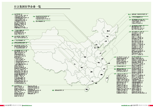
日立集团在华企业一览
吉林
辽宁
重庆: 重庆日立电梯营销工程有限公司 四川: 日立(中国)有限公司 成都分公司 东方日立(成都)电控设备有限公司 四川日立电梯营销工程有限公司 广东: 日立(中国)有限公司 广州分公司 日立(中国)有限公司 深圳分公司 东莞歌乐东方电子有限公司 东莞住秀电子有限公司 佛山捷贝汽车配件有限公司 港立电梯工程(深圳)有限公司 歌乐东方有限公司 广东日立工机有限公司 广州日滨科技发展有限公司 广州日立冷机有限公司 广州日立楼宇设备国际贸易有限公司 广州日立压缩机有限公司 广州日立优喜雅汽车配件有限公司 华南电线加工有限公司 日立电梯(中国)有限公司 日立粉末冶金(东莞)有限公司 日立高新技术(深圳)贸易有限公司 日立化成工业(东莞)有限公司 日立环球存储科技(深圳)有限公司 日立金融设备系统(深圳)有限公司 日立金属(东莞)耐磨合金有限公司 日立金属(东莞)特殊钢有限公司 日立蓄电池(东莞)有限公司 日立医疗(广州)有限公司 深圳日禾国际货运有限公司 深圳日立电梯销售有限公司 信宜日红树脂化工有限公司 日立环球储存产品(深圳)有限公司 深圳海量存储设备有限公司 深圳日立赛格显示器有限公司 香港: 日立远东有限公司 日立物流(香港)有限公司 日立数据系统有限公司 日立高科技香港有限公司 日立空调系统(香港)有限公司 香港AIC有限公司 香港日立化成工业有限公司 日立金融(香港)有限公司 日立金属(香港)有限公司 日立电线亚洲有限公司 日立工机亚洲有限公司 日立电梯工程(香港)有限公司 日立保险服务(香港)有限公司 香港日立有限公司 日立金属亚都美特(香港)有限公司 日立麦克赛尔亚洲有限公司 日立视听媒体股份有限公司 瑞萨香港有限公司
北京 河北 天津
山东
陕西 江苏
安徽
海南: 海南日立电梯有限公司
日立空调销售公司介绍
公司介绍上海群坛机电设备有限公司一直秉着日立在中国的一贯理念“以技术贡献社会”,坚持“和”、“诚”以及“开拓者精神”的创业精神,力争成为与顾客及社会共同飞跃发展的公司。
“和” 凡事要经过充分酝酿和讨论,一旦形成决定,相关人员须同心同德、全力以赴。
“诚” 无论对人对己都要直率,对自己的工作要全心全意。
作为全球化企业公民,要把社会诚信放在第一位,以诚实的态度开展企业活动。
“开拓者精神” 勇于向未知的事物挑战,不断提高开发新产品、新技术的积极性。
努力通过创新来为社会基本问题的解决发挥作用。
正是基于这一理念,群坛企业历经了十几年跳跃式的发展,业务领域从单一的项目施工到为客户提供整体的工程技术解决方案,以及现在正致力发展的暖通工程。
产品型号日立空调分为家用空调以及商用空调,中央空调。
而家用空调主要产品为完全直流变频挂机,定速挂机,完全直流变频柜机,定速柜机。
完全直流变频挂机RAS/C-25BVX RAS/C-35BVX RAS/C-25BVY RAS/C-35BVY RAS/C-35BVYB RAS/C-50A VX RAS/C-35A VX RAS/C-25AVX RAS/C-35A VY RAS/C-25A VY RAS/C-35A VZ RAS/C-b26AX定速挂机RAS/C-26BHY RAS/C-36BHY RAS/C-32BHY RAS/C-36BHYB RAS/C-36BHN RAS/C-36BCY RAS/C-26BCY RAS/C-36AHY RAS/C-32AHY RAS/C-26AHY RAS/C-35AHZ RAS/C-35AHR RAS/C-32AHR RAS/C-B26BH RAS/C-A33CH RAS/C-A50KH RAS/C-A27AC RAS/C-A35KC RAS/C-A38AH完全直流变频柜机RAP/C-L72BVZ RAP/C-L72BVZB RAP/C-L72BVXB RAP/C-L72BVX RAP/C-L63BVX RAP/C-L53BVX RAP/C-L72BVYB RAP/C-L72BVY RAP/C-L61BVY RAP/C-L50BVY RAP/C-L72A VY RAP/C-L72AVYB RAP/C-L72A VX RAP/C-L72A VXB RAP/C-L63A VX RAP/C-L53AVX定速柜机RAP/C-L72BHZ RAP/C-L72BHZB RAP/C-L62BHZ RAP/C-L62BHZB RAP/C-L53BHZ RAP/C-L53BHZB RAP/C-L53BHN RAP/C-L53BHNB RAP/C-L62BHN RAP/C-L62BHNB RAP/C-L72BHN RAP/C-L72BHNB RAP/C-L53BHY RAP/C-L53BHYB RAP/C-L62BHY RAP/C-L62BHYB RAP/C-L72BHY RAP/C-L72BHYB RAP/C-A72QHB RAP/C-A52AHB RAP/C-B50LH RAP/C-C61JH RAP/C-A72SH RAP/C-A72RHD RAP/C-A72QH RAP/C-A52AH RAP/C-A72PH RAP/C-B50LHS RAP/C-C61JHS RAP/C-A72SHS商用机RAP/C3-a72JH RAP/C3-A120DH RAP/C3-A120DHD发展目标只有起点没有终点,而所有群坛人所认同的起点就是“信誉”,因而“成就事业从信誉开始”就成为了我们的核心价值观和经营理念。
日立工业设备系统有限公司HITACHI L100系列变频器快速参考指南说明书

•Single-phase Input 200V Class •Three-phase Input 200V Class •Three-phase Input400V ClassManual No. NB5412XD • Dec. 2003Hitachi Industrial Equipment Systems Co., Ltd.HITACHIL100 Series Inverter Quick Reference GuideCaution: Be sure to read the L100 Inverter Manual andfollow its Cautions and Warnings for the initial productinstallation. This Quick Reference Guide is intended forreference use by experienced users in servicing existinginstallations.Power Circuit Terminals–002NFE/NFU, –004NFE/NFU, –005NFEJumper+1L1L2N/L3U/T1V/T2W/T3ChassisGround–007 to 022NFE/NFU, –037LFU, 004 to 040HFE/HFUJumper+1L1L2N/L3U/T1V/T2W/T3ChassisGround–055LFU, –075LFU, 055HFE/HFU, 075HFE/HFU Jumper+1L1L2N/L3U/T1V/T2W/T3ChassisGroundControl Circuit TerminalsTerminalName Description Ratings and NotesP24+24V for logic inputs24VDC supply, 30 mA max.(Notes: Do not use for network powerDo not short to terminal L)1, 2, 3, 4, 5Intelligent (program-mable) discrete logicinputs 27VDC max. (use P24 or an external supply referenced to terminal L), 4.7k Ω input impedance11, 12Discrete logic outputs 50 mA max. ON current,27 VDC max. OFF voltage L (top row)GND for logic inputs Sum of input 1 to 5 currents (Note: Do not ground)CM2Common for logic outputs 100 mA max for sum of terminals 11 and 12 currents FMPWM output0 to 10VDC, 1 mA max., 50% duty cycle L (bottom row)Common for analog inputs Sum of OI, O, and H currents (return)OIAnalog input, current4 to 19.6 mA range, 20 mA nominalH O OI FM P24L Analog inputsAnalog outputsAlarm relayLogic outputsLogic inputsL 54321CM21211AL0AL1AL2OAnalog input, voltage0 to 9.6 VDC range, 10VDC nominal, 12VDC max., input impedance 10 k ΩH +10V analog reference 10VDC nominal, 10 mAmax.AL0Relay common contact Contact rating Max resistive load = 250V AC, 2.5A; 30VDC 3A;Max inductive load = 250V AC, 0.2A; 30VDC 0.7AMinimum load = 5VDC 100mA,100V AC, 10mAAL1Relay contact, normally closed during RUN AL2Relay contact,normally open during RUNTerminal NameDescription Ratings and NotesBasic Wiring DiagramThe following wiring diagram shows the power and motor connec-tions for basic operation. The optional signal input wiring supports external Fwd and Rev Run command, and a speed potentiometer.(L1)R (L2)S (N/L3)T(T2)V(T3)W(T1)U MotorForwardLOHReverseAlarm contacts, 1 Form CRun signalFrequency arrival signal Open collector outputs:External speed reference pot.L100From 3-phase power input source (See specifications label on inverter for details)Logic output commonLoadLoadAnalog common Analog referenceP2421CM21211AL0AL1AL2Inputs:Inverter Keypad Operation•Run/Stop LED – ON when the inverter output is ON and the motor is developing torque, and OFF when the inverter output is OFF (Stop Mode).•Program/Monitor LED – ON when the inverter is ready for parameter editing (Program Mode). It is OFF when the parameter display is monitoring data (Monitor Mode).•Run Key Enable LED – ON when the inverter is ready to respond to the Run key, OFF when the Run key is disabled.•Run Key – Press this key to run the motor (the Run Enable LED must be ON first). Parameter F_04, Keypad Run Key Routing, determines whether the Run key generates a Run FWD or Run REV command.•Stop/Reset Key – Press this key to stop the motor when it is running (uses the programmed deceleration rate). This key will also reset an alarm which has tripped.(continued, next page...)Hz POWER ARUN PRGMINMAXHITACHIFUNC.STR1250.0Parameter Display Run/Stop LEDProgram/Monitor LEDRun Key Enable LEDRun Key Power LEDDisplay Units LEDs Hertz AmperesPotentiometer Enable LED Potentiometer Stop/Reset KeyFunction KeyUp/Down Keys Store Key•Potentiometer – Allows an operator to directly set the motor speed when the potentiometer is enabled for output frequency control.•Potentiometer Enable LED – ON when the potentiometer is enabled for value entry.•Parameter Display – A 4-digit, 7-segment display for parame-ters and function codes.•Display Units: Hertz/Amperes – One of these LEDs will be ON to indicate the units associated with the parameter display.•Power LED – ON when the power input to the inverter is ON.•Function Key – This key is used to navigate through the lists of parameters and functions for setting and monitoring parameter values.•Up/Down Keys – Use these keys alternately to move up or down the lists of parameter and functions shown in the display, and to increment/decrement values.•Store Key – When the unit is in Program Mode and the operator has edited a parameter value, press the Store key to write the new value to the EEPROM.Keypad Navigation Mapc 91c 0112b 89b 0112A 98A 0112121212C ––12b ––12A ––F 04F 0112d 09d 0112o.0123.4Edit12Increment/decrement valueWrite datato EEPROMDisplay dataMonitor Mode Program ModeFUNC.STRFUNC.FUNC.12Return to parameter listFUNC.FUNC.Store as powerup defaultpowerdownSelect ParameterEdit ParameterPowerup TestThe Powerup Test procedure uses minimal parameter settings to run the motor. The procedure describes two alternative methods for commanding the inverter: via the inverter keypad, or via the logic terminals.•Check power input and motor output wiring (see page4 diagram).•If using logic terminals for testing, verify correct wiring on [P24], [FW], [H], [O], and [L] (bottom row) per the diagram on page4.•Reverse [RV] input wiring (defaults to terminal [2]) is optional.Step Description Via Keypad Via LogicTerminals1Set speed command source setting A_01 = 00(keypad pot.)A_01 = 01,[H–O–L] input2Set Run FW command source A_02 = 02(Run key)A_02 = 01,[FW] input3Set Run REV command source —C_02 = 01,[RV] input4Set motor base freq.A_03 = 605Set keypad display to monitor freq.Access D_01, press Func key, display will show 0.0Perform safety check Disconnect load from motor6Turn keypad pot.to MIN position Ensure voltage on [O]—[L] termi-nals= 0V7Run Forward command Press Run key Turn ON the[FW] terminal8Increase speed Rotate keypadpot. CW dir.Increase voltage at [O]9Decrease speed Rotate keypadpot. CCW dir.Decrease voltage at [O]10Stop motor Press Stop key Turn OFF the[FW] terminal11Run Reverse command (optional)—Turn ON the [RV]terminal12Stop motor—Turn OFF the[RV] terminalError CodesThe L100 series inverters will trip on over-current, over-voltage, and under-voltage to protect the inverter. The motor output turns OFF, allowing the motor to free-run to a stop. Press the Stop/Reset key to reset the inverter and clear the error.Basic Error CodesErrorCode Name Probable Cause(s)E01Over current event whileat constant speed •Inverter output was short-circuited •Motor shaft is locked•Load is too heavy•A dual-voltage motor is wired incorrectlyNote: The L100 will over current trip at nominally 200% of rated currentE02Over current event duringdecelerationE03Over current event duringaccelerationE04Over current event forother conditions •DC braking power(A_54) set too high•Current transformer / noise errorE05Overload protection•Motor overload is detected by theelectronic thermal functionE07Over voltage protection•DC bus voltage exceeds a threshold,due to regenerative energy from motor E08EEPROM error•Built-in EEPROM memory experi-enced noise, high temperature, etc. E09Under-voltage error•DC bus voltage decreased enough tocause a control circuit faultE11E22CPU error•Built-in CPU had internal errorE12External trip•[EXT] input signal detectedE13USP (Unattended StartProtection)•When (USP) was enabled, an error occurred when power was applied while a Run signal was presentE14Ground fault•A ground fault was detectedbetween the inverter output and themotor. This feature protects theinverter, and does not protect humans. E15Input over-voltage•Input voltage was higher than thespecified value, 60 sec. after powerup E21Inverter thermal trip•Inverter internal temperature isabove the thresholdError Trip ConditionsUse function code D_08 to access the error trip conditions for the current error as shown in the table below. Use the Up and Down arrow keys to scroll through the trip condition parameters.E35Thermistor•Thermistor input, [THM] and [L], is over the temp. threshold---Under-voltage (brown-out) with output shutoff•Low input voltage caused theinverter to turn OFF the motor output and try to restart. If unsuccessful, a trip occurs.StepDisplay1. Access D_08d 082. Press Function KeyIf no error:_ _ _If error exists:Exx(error code)3. Press Up/Dn key (if error exists)Output frequency at trip point:10.0Motor current at trip point:0.025DC bus voltage at trip point:189.8Error CodeNameProbable Cause(s)12Restoring Factory Default SettingsActionDisplayFunction/ParameterPress ,or as needed.b --“B” Group selectedPress .b 01First “B” Group parame-terPress/holduntil...b 85Country code forinitialization selected Press . If setting iscorrect, then skip next step.0200 = Japan 01 = Europe02 = United StatesTo change country code, press or to set; to store.Press .b 85Country code forinitialization selected Press .b 84Initialization function selectedPress .000 = disable initialization, clear trip history only Press .011 = enable initialization Press .b 84Initialization now enabled to restore all defaultsPress/hold , ,and . Do not release yet.b 84First part of key sequencePress/hold (STOP)for 3 seconds, then release.d 00Final part of special sequence, “D_00” is flashingNow release the all keys together, only after “D_00” display begins blinking.EU USA JP Default parameter country code shown during initializationInitialization is complete.d 01Function code for output frequency monitor shownFUNC.12FUNC.1FUNC.12STR FUNC.2FUNC.1STR FUNC.12Note: After initializing the inverter, use the Powerup Test on page 8 to get the motor running again.Parameter Tables“D” Group: Monitoring FunctionsFunc. Code Name / DescriptionUnits D_01Output frequency monitor Hz D_02Output current monitor A D_03Rotation direction monitor—D_04Process variable (PV), PID feedback monitor %D_05Intelligent input terminal status—D_06Intelligent output terminal status—D_07Scaled output frequency monitor(output frequency x B_86 scale factor)User-defined D_08Trip event monitor —D_09Trip history monitor—DirectionForward Stop Reverse21435Terminal NumbersON OFF1211AL Terminal NumbersON OFFTrip History Navigation MapE 0760.0124.00270.01212d 0812o.00Display dataMonitor Mode12FUNC.FUNC.d 09____NoError code Output frequency at trip point Motor current at trip point DC bus voltage at trip pointFUNC.Y esNo errorError (n-1) exists?NoY esE 03E 05____No historyFUNC.Error (n-2) exists?NoY esFUNC.____FUNC.FUNC.12FUNC.No historyError exists?Parameter tables for user-settable functions follow these conven-tions:•Some parameters specify an option code. Where applicable, the options codes will be in a bulleted list in the Name/Description column.•The default values apply to all models unless otherwise noted for each parameter... –FE (Europe) / – FU (U.S.) / –FR (Japan).•Some parameters cannot be edited during Run Mode, and certain Software Lock settings (B_31) can prohibit all edits. If in doubt, place the inverter in Stop Mode or consult the inverter manual for details.“F” Group: Main Profile ParametersFunc.Code Name / Description DefaultValueSetValueF_01Output frequency setting0.0 F_02Acceleration (1) time setting10.0 F_03Deceleration (1) time setting10.0 F_04Keypad Run key routing•00Forward•01Reverse00“A” Group: Standard FunctionsFunc.Code Name / DescriptionDefaultValue–FE / –FU /–FRSetValueA_01Frequency source setting•00Keypad potentiometer•01Control terminal•02Function F_01 setting01 / 01 / 00A_02Run command source setting•01Input terminal FW or RV (assign-able)•02Run key on keypad, or digitaloperator01 / 01 / 02A_03Base frequency setting50.0 / 60.0 /60.0A_04Maximum frequency setting50.0 / 60.0 /60.0A_11O/OI–L input active range startfrequency0.0A_12O/OI–L input active range end frequency0.0A_13O/OI–L input active range start voltage0A_14O/OI–L input active range end voltage100A_15O/OI–L input start frequency enable•00Use A_11 starting value)•01Use 0 Hz01A_16External frequency filter time constant8A_20Multi-speed frequency setting0A_21 A_22 A_23 A_24 A_25 A_26 A_27 A_28 A_29.. ..A_35Multi-speed frequency settings0 / 0 / 50 / 0 / 100 / 0 / 150 / 0 / 200 / 0 / 300 / 0 / 400 / 0 / 500 / 0 / 600 / 0 / 0A_38Jog frequency setting 1.0 A_39Jog stop mode•00Free-run stop, jogging disabledduring motor run•01Controlled deceleration, joggingdisabled during motor run•02DC braking to stop, joggingdisabled during motor run00A_41Torque boost method selection•00Manual torque boost•01Automatic torque boost00A_42Manual torque boost value11 A_43Manual torque boost frequency adjust-ment10.0A_44V/f characteristic curve selection•00V/f constant torque•01V/f variable torque00A_45V/f gain setting100 A_51DC braking enable•00Disable•01Enable00 A_52DC braking frequency setting0.5 A_53DC braking wait time0.0 A_54DC braking force during deceleration0 A_55DC braking time for deceleration0.0 A_61Frequency upper limit setting0.0 A_62Frequency lower limit setting0.0 A_63A_65A_67Jump (center) frequency setting0.0A_64 A_66 A_68Jump (hysteresis) frequency widthsetting0.5A_71PID Enable•00PID operation OFF•01PID operation ON00A_72PID proportional gain 1.0A_73PID integral time constant 1.0A_74PID derivative time constant0.0A_75PV scale conversion 1.00A_76PV source setting•00[OI] terminal (current input)•01[O] terminal (voltage input)00A_81A VR function select•00A VR enabled•01A VR disabled•02A VR enabled except during decel02 / 00 / 02“B” Group: Fine-tuning FunctionsA_82A VR voltage select 230/230/200400/460/400A_92Acceleration (2) time setting 15.0A_93Deceleration (2) time setting15.0A_94Select method to switch to Acc2/Dec2 profile•002CH input from terminal •01transition frequency00A_95Acc1 to Acc2 frequency transition point 0.0A_96Dec1 to Dec2 frequency transition point 0.0A_97Acceleration curve selection •00Linear •01S-curve 00A_98Deceleration curve selection •00Linear •01S-curve00Func. Code Name / DescriptionDefault Value –FE / –FU /–FRSet ValueB_01Selection of automatic restart mode •00Alarm output after trip, automatic restart disabled •01Restart at 0Hz•02Resume operation after frequency matching•03Resume previous freq. after freq. matching, then decelerate to stop and display trip info00B_02Allowable under-voltage power failure time1.0B_03Retry wait time before motor restart1.0B_12Level of electronic thermal setting Ratedcurrent ofeach inverter B_13Electronic thermal characteristic•00Reduced torque•01Const. torque01 / 01 / 00B_21Overload restriction operation mode•00Disabled•01Enabled for accel and constantspeed•02Enabled for constant speed only01B_22Overload restriction setting Ratedcurrentx 1.25B_23Deceleration rate at overload restriction 1.0B_31Software lock mode selection•00Low-level access, [SFT] blocksedits•01Low-level access, [SFT] blocksedits (except F_01 and Multi-speedparameters)•02No access to edits•03No access to edits except F_01 andMulti-speed parameters01B_32Reactive current settingNote: For Japanese (–FR) versions, only–055LFR, –055HFR, –075LFR, and–075HFR models support this function.58% rated currentB_81[FM] terminal analog meter adjustment80B_82Start frequency adjustment0.5B_83Carrier frequency setting 5.0 / 5.0 /12.0B_84Initialization mode (parameters or triphistory)•00Trip history clear•01Parameter initialization00B_85Country code for initialization•00Japan version•01Europeversion•02US version01 / 02 / 00B_86Frequency scaling conversion factor 1.0B_87STOP key enable•00Enable•01Disable00“C” Group: Intelligent Terminal FunctionsB_88Restart mode after FRS •00Restart from 0Hz•01Restart from frequency detected from actual speed of motor00B_89Data select for digital operator OPE-J •01Output frequency (D_01)•02Output current (D_02)•03Motor direction (D_03)•04PID PV feedback (D_04)•05Input states for input terminals (D_05)•06Output states for output terminals (D_06)•07Scaled output frequency (D_07)01Func. Code Name / DescriptionDefault Value –FE / –FU /–FRSet ValueC_01Terminal [1] function Fifteen option codes available (see page 21)00C_02Terminal [2] function 01C_03Terminal [3] function 02 / 16 / 02C_04Terminal [4] function 03 / 13 / 03C_05Terminal [5] function 18C_11Terminal [1] active state•00Normally open [NO]•01Normally closed [NC]00C_12Terminal [2] active state00C_13Terminal [3] active state00C_14Terminal [4] active state00 / 01 / 00C_15Terminal [5] active state00C_21Terminal [11] function Six optioncodes available(see page22)01C_22Terminal [12] function00 C_23[FM] signal selection Three optioncodes available(see page22)00C_31Terminal [11] activestate (–FU)•00Normallyopen (NO)•01Normallyclosed (NC)— / 00 / —Reserved (–FE / –FR)00 / — / 00 C_32Terminal [12] activestate (–FU)— / 00 / —Terminal [11] activestate (–FE / –FR)00 / — / 00C_33Alarm relay terminalactive state01C_41Overload level setting Ratedcurrent ofeach inverter C_42Frequency arrival setting for accel0.0C_43Arrival frequency setting for decel0.0C_44PID deviation level setting 3.0C_91Debug mode enable•00Display•01No display 00Func.Code Name / DescriptionDefaultValue–FE / –FU /–FRSetValueIntelligent Input Terminal ListingSymbol Code Input Terminal NameFWD00Forward Run/StopRV01Reverse Run/StopCF102Multi-speed select, Bit 0 (LSB)CF203Multi-speed select, Bit 1CF304Multi-speed select, Bit 2CF405Multi-speed select, Bit 3 (LSB)JG06Jogging2CH092-stage accel and decelFRS11Free-run stopEXT12External tripUSP13Unattended start protectionSFT15Software lockAT16Analog input voltage/current sel.RS18Reset inverterPTC19PTC thermistor thermal protectionIntelligent Output Terminal ListingAnalog Input ConfigurationThe following tables show the parameter settings required for vari-ous analog input signal types.Analog Output Function ListingThe following table shows all three functions available for assign-ment to the analog output terminal:•Terminal [FM], option set by C_23Symbol Code Input Terminal NameRUN 00Run signalFA101Freq. arrival type 1 – constant speed FA202Freq. arrival type 2 – over-frequency OL 03Overload advance notice signal OD 04Output deviation for PID control AL05Alarm signal[AT]External Frequency Command InputOFF [O] — [L]ON[OI] — [L](not assigned to any inputterminal)Summation of [O] — [L] and [OI] — [L]Option Code Function Name Description Corresponding Signal Range 00Output frequency Actual motor speed, represented by PWM signal0 to max. freq. in Hz01Output currentMotor current (% of maximum rated output current), represented by PWM signal0 to 200%02Digital output frequencyOutput frequency 0 to max. freq. in HzNotes:。
全球e-服务客户参考指南说明书

OverviewGlobal e-Service is an internet-based service that allows the collection and viewing of Hitachi wheel loader data.The purpose of this interactive guide is to provide customers with an overview to the applications within Global e-Service (GeS).To jump to a topic, click the page number.Table of Contents Login (2)News (3)Control Panel (3)ConSite (4)Machine (4)Parts (5)Utility (5)Password Maintenance (6)User Guides......................................................................................... 7 - 26•ConSite ISF•ConSite Shot•Owner’s Site•HCMA TelematicsAccess the Hitachi Dealer Direct website () and click the Global e-Service link.Enter your User ID and Password.Note: The use of a single ID by several persons is strictly prohibited. If you do not have an ID, request one by contacting the Global e-Service administrator.The Global e-Service menu is displayed. Click the title toexpand the desired menu.NEWSView important information.•Receive notifications, system update messages.CONTROL PANELPerform routine account management.•Reset your password.•Correct misspelled information in the name fields.•Update your email address.•Change your Country/Region, Job Type and Language using the dropdown menus.CONSITEAccess manuals, submit parts orders and inspection reportsConSite Manual•Dedicated to “Shop Talk” articles and related information for customers.Mail Setting•Allows the end user to set email address to receive alerts, monthly reports, and oil diagnostic reports.•Allows the end user to set the type of alerts to receive.•Dealer manual allows the end user to view “Shop Talk” Articles. This is the same as the ConSite Manual.ConSite ISF (Intelligent Parts Finder)•Search for and order Hitachi parts•ConSite ISF Quick Start Guide (click here to view the guide) ConSite Shot Web (Mobile App)•Search for machine inspection reports•ConSite Shot User Guide (click the here to view the guide)MACHINEMonitor your machine’s operational status, location and connect to ISO standard telematics.Owner’s Site•View machine maintenance cycles, history of owner machines and useful operational information.•Owner’s Site for Customer’s Reference Guide (click the here to view the guide)Geographic Information Systems (GIS)•Track machine locationsISO API (ISO154513-3) for Customers•The HCMA AEMP Telematics Data Standard V2.0 (token) is used to provide real-time connection for HCMA dealers.•HCMA AEMP Telematics Data Standard V.2 (ISO154153-3) Reference Guide for Customers (click the here to view the guide)PARTSView and monitor the status of parts orders placed in ConSite ISF.UTILITYAccess downloadable Global e-Service application manuals and Quick Guides.⇒ After 75 days of inactivity, your Global e-Service account will be locked.Follow the instructions on the screen to request to have the accountunlocked.User GuidesConSite ISF allows you to order parts directly from HCMA. This Quick Start Guide includes steps on how to locate parts and place orders.• From the main menu, click on ‘ConSite’ and select ‘ConSite ISF’ from the list.• By default, the system will display Parts Catalogs for your machine.• Select the appropriate catalog.• Click the component subfolder to reveal the available parts.• Select the desired part from the list.•An illustration of the component from the parts catalog will appear. •The Parts list will display below. Note: parts displayed are based on availability.•From the list, select the desired part. Click on the to reveal associated parts.•The suggested quantity will display. Increase or decrease the Purchased Quantity based on your need.•After the items have been selected, click the ‘Add to Cart’ button.•View the items in the cart.•Increase/decrease or delete items as needed.•Click the “ConSite Web Shop Order” button to submit the request.•Review the Customer Information.•Enter the required information.•To request a quote, select the“Request Quotation” box.•To place the order, click the“Order” button.• After the order hasbeen placed, you will receive an email confirmation.• Scroll to the bottom and click the order details link to view the order status.• The Hitachi Direct manager will contact you to confirm the order and steps on how to remit payment.Follow the steps below to access the app.1. Download the free ConSite Shot app from the Apple or Google Playstore.2. When the app opens, tap [Allow] to grant access to the machinelocation.3. Allow ConSite to access photos and media files on your device.4. Enter your Global e-Service ID and password. If you do not have an ID,request one by contacting the Global e-Service administrator,*********************.5. Read and Agree to the Terms and Conditions.Note: After the app has been downloaded, you will not have to accept the push notifications, allow access to location, media files or agree to the Terms and Conditions again.REPORT LIST VIEWNote : If reports have previously been uploaded, it will display when theapp is opened.• Reports uploaded to Global e-Service will be marked .• Temporarily saved reports will be marked and the text willappear in blue.Distance between your location and themachine.View machine’s location in GoogleMaps.Narrow or expand the search by selecting the desired radius from thedropdown menu.Scan the machine’s QR code to populate the report with the machine’s information.Tap the [Machine icon ] to search using the machine’s information.After selecting the machine, you will be directed to the Create Report screen. Tap the [Camera icon ] to take a photo or select a photo from your photo library. Take Photo - snap a picture of the area using the camera on your mobile device and attach to the report by tapping the [Attach icon ].Select from Photo library - retrieve photos from your device. Tap the [Download icon ] and photos will be automatically attached to the report. Note : Maximum 25 photos can be attached to the report. Videos cannot be attached.After the photo has been attached,Specify the main component (area of photo taken) from thedropdown menu.Enter comments to describe the overall inspection result.Select the condition of the machine from the dropdown menu.Save or delete the photo before attaching to the report.: At least one photo is required to save the report.icon] to add arrows to specify the spot.Rotate photo 90° counterclockwise.] button on your device to return to the Create ReportThe machine information will auto-populate the appropriate fields – PIN/VIN, Model Code/Name, etc.Note : It is also possible to create inspection reports of other brand machines. In those cases, enter the information manually.Scroll to the bottom of the page to continue capturing information. Annual Inspection (Legal Inspection) – Check “Unexecuted” if the annual inspection has not been executed.Last annual inspection date – the datewill auto-populate. Check the box toinput the year and month of inspection only.Annual inspection done by - select the inspector from the dropdown menu, i.e. In-house, Customer, Others.Condition - select the status of themachine from the dropdown menu. If an emergency repair is required, check the box.Opportunity - select the future opportunity of the machine, e.g. reorder prospect, resale prospect, etc.Temporary Save – saves a temporary copy of the report to Global e-Service to allow edits.Save – saves the report to your mobile device and uploads to Global e-Service. Share URL via e-Mail – click the [Camera icon ] to share a report URL. *Internet connection is required.Note: Reports are uploaded to Global e-Service. To view or download the report access ConSite Web.To view or download the report access ConSite Web in Global e-Service.Search Result Options•Register – register the next annual inspection date.•Export Report – Download the report as an Excel document.•Download photos – to your laptop.•Link to FIR – upload photos and report information to the FIR.•Report No. – include this number on the parts order and receive a2.5% parts discount.Owner’s Site allows customers to manage maintenance cycles, history of owner machines, useful information for effective operation management and maintenance plan based on the operation data transmitted from the machines.This guide provides a description of the main tabs within Owner’s Site.• Access Global e-Servicefrom the Hitachi Direct website ( ).• Click on the Global e-Service website login link. Enter your User ID & Password.• From the main menu,click on ‘Machine’ and select “Owner’s Site” from the list.• To setup widgets, follow theInteractive tutorial guide on the Home/Dashboard welcome screen.• From theHome/Dashboard page, review News, Machine and System Events (if available). • Select Owner Machine List from the menu.Owner Machine List • The default view displays the owner’s machine ID, Serial Number,the current hour meter and the delivery date.• Click [>] symbol on the machine field to display machineinformation.• To reveal more information about the machine, click the icons at the top of Owner Machine List page. Machine Information • This page contains an image of the machine and contract information. • Review the latest machine information, History List, and history of comments (if available).• Click the “Register Repair or Inspection” button to input the information (see image below).Operation Info•Select the display period (date) and display range (time) from the drop-down menus.•Click ‘Search’.View the machine’s operation information for the selected time period.•Total Hours•Mileage•Engine on Hours•Fuel Remaining•Hour Meter•Mileage•Low Idling TimeMaintenance•Select the ‘Recommended Schedule’ or ‘Maintenance Schedule’ tab to view maintenance information for machine parts based on intervalhours.•Click the icon to input updated maintenance information.Location•Click the [Location] tab to check the machine’s location.ISF (ConSite Parts Finder)•Click this tab to start a ConSite ISF parts order.The HCMA AEMP Telematics Data Standard V2.0 (token) is used to provide real-time connection for HCMA dealers. This guide will provide steps for how to use the token to access information. Step 1: Send an email to *********************. Include your Global eService User ID. Step 2: “GeS ISO API (ISO15143-3) for Customer” will populate in Global e-Service within one business day.Step 3:Get token. Enter the URI and required information into your Fleet Management System. URI: https:///ISO_API/api/PublishToken Required Information: grant_type = create a password that will be used each time you access the token/URI. username = Global e-Service ID. Password = Global e-Service password. Step 4:Get the Telematics data. Page Number for all machines https:///ISO_API/api/v4/FleetAlert/[Any page number] PIN for single machine https:///ISO_API/api/v4/FleetAlert/Equipment/ID/[Any PIN] Step 5:Request Data Points: • Equipment Header • Location • Cumulative Operating Hours • Fuel Used (Last 24) • Distance • Fuel Remaining • Nonproductive Idle Hours • Caution Description Step 6: Recreate token. Enter the URI and required information. Note : Token expires in 60 minutes. https:///ISO_API/api/PublishToken grant_type = refresh_token code = specify the ‘refresh token’ when the access token is issued.。
日立产品介绍
˙售后产品·保养用品
刹车片
制动碟
减振器
˙应用技术·工业机器 铁路车辆用产品
垂向减振器
横向减振器
抗蛇行减振器
车间减振器
动力转向器
动力转向泵
水泵
燃料泵
燃料喷射器
电子节气门
空气流量传感器
点火线圈
汽车检测功能搭载日立诊断监视仪
点火线圈检测仪
9
电池检测仪
便携式电源(12V、24V)
地震对策产品
可变阻尼减振系统
www.hitachi-automotive/cn/
产品介绍
Printed in Japan 2019.07
日立汽车系统,致力于为“人·车·社会”
创造新的价值,并为世界实现富足社会贡献产品、
系统和解决方案
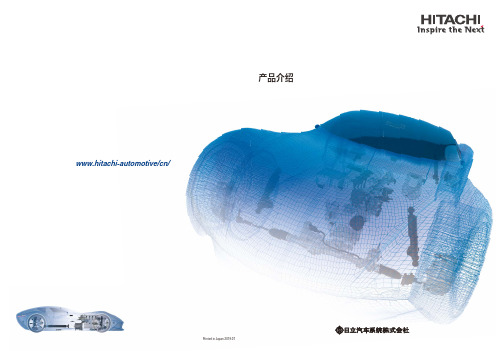
汽车作为可在环境、安全、舒适各领域提供诸多附加价值的交通工具持续进化至今。 日立汽车系统以机电一体控制技术的优势为基础,在提升原有动力总成系统、底盘系统、 先进驾驶辅助系统(ADAS)等事业领域附加价值的同时,针对越发重要的电动化和自动 驾驶关键技术领域,着力开发和提供支持其发展的系统。 另外,从IoT到人工智能、信息、通讯、安全技术等,日立汽车系统为下一代移动提供 日立集团支持网联汽车的系统解决方案。以创造富足的社会为目标,为“人·车·社会” 的互联创造新的价值。
混合动力车/电动车系统
自动驾驶系统/360度探测系统
混合动力车用电机
EV车用逆变器
HEV/PHEV/EV车用逆变器
HEV/PHEV/EV车用逆变器
EV: Electric Vehicle HEV: Hybrid Electric Vehicle PHEV: Plug-in Hybrid Electric Vehicle
日立中央空调经销商公司介绍
日立中央空调经销商上海群坛机电设备有限公司是一家日立中央空调品牌的经销商,近年来,在国家宏观政策调控下,中央空调市场表现异常活跃,2011年销售额大幅增长。
市场的高速增长需要以产能支持为前提。
空调企业唯有专业生产,才能满足高速增长的产能需求,助力行业市场发展。
中央提出了节能减排的要求,工业建筑能耗尤其受到重视。
而在工业建筑能耗中暖通空调占到了很大的份额。
空调节能立足于系统解决方案,从能源成本、单位面积能耗及运行成本等等都要面面俱到。
在暖通空调行业中,系统节能必然在未来有一个庞大的市场。
所谓专业生产是指站在行业发展最前沿,以最新的技术、最新的产品面向受众。
在创新中求稳,是一个企业展现智慧的关键点。
在原有技术的前提下,保证质量节能保证功效再开创新的技术。
将节能纳入创新的具体策略中,达到功效与节能完美融合。
“节能”这个概念会越来越成为企业和市场竞争的一个重要权衡点。
在国家节能政策的推动下,高能效的节能中央空调已经成为市场主流,变频空调也得到普及。
不管是家用空调还是商用中央空调在2011年都迎来了一个新的突破。
据了解,到目前,国内节能环保央空调品牌厂商以低碳环保为理念,不断创新,新型高效离心式冷水机组等新产品和新技术在行业内保持领先地位。
在本文中,我们日立专业人员主要为广大消费者讲述有关日立SET-FREE WS 水源变频多联式中央空调的一些简单功能信息,以及对于现如今的绿色能源的状况。
SET-FREE WS水源变频多联式中央空调日立水源多联式空调系统成功将水源热泵技术、多联机控制技术、直流变频驱动技术和R410A环保工质等结合在一起,糅合了风冷多联式变频空调和水冷式冷水机组两大类产品的技术优点,通过高效板式换热器和中间介质循环水,利用海洋、土壤、工业废热、城市污水等低品位热源中的热能进行制冷供暖,极大地节约了能源。
水源多联机系统图适用的水源范围水源多联式空调系统不受常规气候的低温和地理区域的限制,可广泛应用于以下水源工况,也可结合其他能源的利用,如太阳能等新能源。
日立es服务器操作方法

日立es服务器操作方法
日立ES服务器的操作方法如下:
1. 打开电源开关,启动服务器。
2. 进入服务器管理界面,可以通过服务器管理网口连接服务器或通过KVM控制台直接操作。
3. 在服务器管理界面,输入用户名和密码进行登录。
4. 在登录成功后,可以使用相关命令行工具或图形界面来进行操作,包括管理硬件设备、配置网络、设置存储等。
5. 如需安装操作系统,可以通过服务器管理界面的虚拟光驱功能加载操作系统安装镜像,并按照提示完成安装过程。
6. 在操作系统安装完成后,可以继续配置服务器相关设置,如网络设置、防火墙设置、远程管理设置等。
7. 根据需求,安装和配置所需的应用程序和服务。
8. 定期进行服务器维护和监控,保持服务器运行稳定。
请注意,具体的操作步骤和命令可能会根据不同的日立ES服务器型号和操作系统版本而有所差异,建议参考相关的日立ES服务器文档或手册以获取详细的操作指南。
HGE产品介绍版

日立小机房电梯——HGEHGE电梯是日立电梯(中国)有限公司特别针对公寓住宅市场开发的新一代安全环保舒适的小机房电梯,综合运用了永磁无齿主机、永磁同步门机和最先进通讯科技,同时糅合各方面的人性化设计。
一、双永磁系统配置:永磁同步曳引机+永磁同步门机相关链接:永磁同步电机具有:功耗小、力矩大、噪音低、体积小、重量轻、调速精度高、调速范围宽、低速性能好等显着优点。
无需机械减速机构,无减速环节损耗,免润滑,节能环保。
由电机直接驱动电梯运行,机械结构变得非常简单,提高了安全性及设备可靠性。
1. 日立HGE永磁同步曳引机领先行业的优异设计■主机专利防脱磁钢设计概要■主机IP41防护等级■主机F级绝缘等级■主机低温升,安全稳定寿命长■主机转矩脉动<1%,运行更舒适■制动器190%额定载荷制动力矩■原装日本进口高精度金属码盘旋转编码器1-1主机专利防脱磁钢设计磁钢(永磁体)是永磁同步主机中的核心材料,日立HGE采用了专利设计:永磁体固定采用专用粘贴剂+铜螺栓压板固定设计将磁钢定位。
杜绝了一般的永磁同步主机直接把磁钢直接粘贴在转子上,存在磁钢脱落导致电机损坏的危险情况。
1-2主机IP41防护等级IP防护等级,指防尘防水的等级。
一般由两个数字组成,数字越大表示防护等级越高。
HGE电梯采用的永磁同步电机,防护等级高达IP41,可有效防尘防水;如果电梯采用防护等级低的电机,在如春夏季多雨期或海边环境湿度稍大的地方,就可能会出现故障、甚至烧电机的情况。
1-3主机F级绝缘等级日立永磁同步主机绝缘等级为真正的F级,所有绝缘材料(包括电线、绝缘薄膜、阻燃型高强度层压玻璃布板等)均严格采用F级绝缘材料,同时电机绕组整体采用真空浸(漆)烘工艺,以确保电机不会出现虚接触情况,使整个线圈绕组包括线圈接驳线头都达到F级的绝缘等级,保证主机可承受最高155℃工作温度。
1-4主机低温升,安全稳定寿命长对于永磁同步电机来说,温升是对电机磁性一个影响因素之一,电机温升过高,会导致电机失磁,这种失磁是永久性的、不可逆的。
- 1、下载文档前请自行甄别文档内容的完整性,平台不提供额外的编辑、内容补充、找答案等附加服务。
- 2、"仅部分预览"的文档,不可在线预览部分如存在完整性等问题,可反馈申请退款(可完整预览的文档不适用该条件!)。
- 3、如文档侵犯您的权益,请联系客服反馈,我们会尽快为您处理(人工客服工作时间:9:00-18:30)。
标准搭载 7 段 LED
● 无需连接编程工具,即可进行 故障代码确认 ● 也可以显示用户数据
EHV系列 程序容量128k, 64k, 32k, 16k步, 4种
EHV-CPU64 ( 64k 步)
EHV-CPU128 (128k 步)
EHV-CPU32 ( 32k 步) EHV-CPU16 (16k 步)
标准搭载 3 种通信端口
Ethernet 通信端口
可进行编程工具和显示器之间的高速通信。 具 有事 件发生时, 或在一定时间内向上位 主站发送数 据的 ASR 功能。 仅用 C P U 模 块即 可实现 集中监视 和数 据 采集等网络 对应。
串行通信端口
此串行通信端口可进行 • RS-232C/422/485 • 专用 / 通用通信的切换 (切换可通过编程工具进行 )。
■ 高速处理, 基本指令 20ns。 ■ 大容量程序存储器,最大128k步。 ■ 大容量注释存储器,最大1M字节。 ■ 标准搭载Ethernet, 串行和USB通信端口。 ■ 配备7段LED故障显示。
1
标准配备 Ethernet 等 3 种通信端口
● Ethernet(10BASE-T/100BASE-TX) ● USB端口(Ver2.0 FullSpeed 12Mbps) ● 串行端口(RS-232C/RS-422/RS-485)
R100 W Y10=W X 2+WM3 WR100=W Y10*10 WR200=W Y10/5
每个回路的符号数
最多(11触点+1线圈 )×32 行
11触点+1线圈
算术指令常时执行
不需要处理框的起动条件 ( 触点 )。
R7E4( 常时 ON) WR0=WM0
32 行
WR0=WM0
同一条件下,可执行多个算术指令 高速运算处理带边沿的线圈、带边沿的处理框
6
通过简单的设定缩短启动时间
①主站与所有的从站通过光缆连接 ②从站站号设定( 旋转开关 ) ③CPU 模块与编程软件 (Control Editor) 在线连接 ④通过 I/O 分配画面, 执行实际安装的读取 通过以上步骤即可完成设定。 缩短了启动时间。 远程从站的 I/O 编号与基本基板相同为: X / Y、 WX / W Y 因为是固定方式所以设计更容易。
日立可编程控制器
满足新时代控制需求的
EHV 系列
紧凑的体积凝缩了下一代的技术和功能
高速大容量,标准配置Ethernet通信端口的 EHV系列
上海多伦能源科技有限公司 联系人:戴朝霞 15301677123
高速大容量, 标准配置 Ethernet 通信端口的 EHV 系列。 也可实现装置的高速 • 高功能控制, 网络系统控制。
事件发信 EHV-CPU
事件发生! TCP/IP 应 用 Ethernet
循环发信
Ethernet
显示器
任务代码通信功能
收
信
应
用
收发信
TCP/IP 应 用 Ethernet
SNTP 客户功能
可从网络上的 N T P 服务器、 S N T P 服务器获得时刻信 息, 自动地进行时刻补偿。
Ethernet
可拆卸式端子台
8/16点模块、 32 点欧洲式端子台式模块的端子台可拆 卸。 可缩短接线 • 维护的时间。
易懂的指令描述
加减乘除 (+、 -、 *、 /) 等, 用日常应用的表示方法来记 述算术指令, 因此即使初级者也可马上进行编程。
WX0000~01 WY0010~11 WY0020~21 插槽编号
主站(EH-ORMM)
从站(EH-ORML)
使用 EHV-CPU 时的构成 主站:最多4台/CPU 从站:最多10台/主站 远程点数:2,048点/主站 主站(EH-ORMM)
从站可连接编程工具、 显示器等 从站(EH-ORML) 从站最多10台/最多2,048点 光纤电缆
■ 规格
项
连接模块 功 能 规 格 输入输出点数 刷新时间 自诊断 反馈运行 I/O分配 主站可安装的槽位 传送速度 传送方式 结构格式 故障校验 故障显示 周边连接端口 最大消息长度 通信协议 逻辑端口 连接形态 电缆长度 异常站处理 电缆 使用电缆及使用连接器
4
EHV系列还具有操作人性化的特长!
配备 7 段 LED 显示
C P U 模块备有 7段 L E D显示。 当故障发生时, 可显示故 障代码。 无需通过个人电脑与编程工具的连接就可进行故障代 码的监视。
异常发生
可在 CPU 的正面更换电池
无需将 C P U 模块从基板上取下, 只需打开机器正面的 电池盖, 即可更换电池。
位 输入 输出 X □ □ □ □□ X □ □ □ □□ 模块内位编号(0~95) 插槽编号EH-ORML的旁边的槽为0 从站编号(0~9) 主站编号(1~4) 字 输入 输出 WX □ □ □ □ WY □ □ □ □ 模块内位编号(0~7) 插槽编号EH-ORML的旁边的槽为0 从站编号(0~9) 主站编号(1~4)
7段LED显示
USB端口 串行端口 Ethernet通信端口
USB 端口
可大幅缩短 通过与个人电脑的 U S B 端口的直接连接, 程序传送时间。 3
EHV 系列
高性能的 Ethernet 通信端口
任务代码通信功能
使用日立专用协议 进行 通信的「任务代码通信专用端 口」 最多可使用4 端口。 连接编程工具可进行 编程和监视, 另外也可连接对应 日立专用协议的 HMI 软件 (SCADA 等 )和显示器。
( )内为程序容量
2
E H V系列的主要特长
高速运算处理
由于搭载了高速 运算处理器, 所以 对于高度复杂的控 制也可以进行高速处理。 • 基本指令20ns • 20k步的程序在不到1ms的时间内即可执行完毕
最大 128k 步的大容量
程序容量 最大128k 步。 对于复杂、 大 型的用户程 序无需担心剩余的步数即可 进行随心所欲的编程。
可对应各种网络
●「Ethernet」TCP/IP 和 UDP/IP ● 对应开放式网络的 「DeviceNet」 和 「PROFIBUS-DP」 ● 日立CPU 链接 以上的通信模块可以最多控制 8台。 另外, 也有对应省配线 系统「A n y W i r e系统」 的接口模块、 也可对应 R S -2 3 2 C/ RS-485/Modbus 通信的串行通信。
除了原来具有的上升沿 D I F、 下降沿 D F N, 另外追加了 带边沿的线圈、 带边沿的处理框。 在 1个处理框中可以记述多达 32 行的算术指令。
R100 WR0=W X0 WR10( WM0)=WM100( WM1) WR2=WR0+WR1 R100 WR0=W X0 WR10( WM0)=WM100( WM1) WR2=WR0+WR1
电池
正常时
异常时
电池连接器
I/O No. 为固定地址方式
采用每个插槽已确定输入输出编号的固定地址方式。 即使改变输入输出模块, 也不会影响到其他插槽。 通过 输入输出编号便可知实际安装的位置, 因此容易维护。
例) 32点输入×1、 32点输入×2 0 1 2 WX □ □ □ □ WX □ □ □ □ 外部输入时 外部输出时 模块内的 字编号(0~7) 插槽编号(16进制0~A) 单元编号(0~5) 远程编号(1~4)
ASR 通信功能
仅进行简单的设定即可和上位主站等进行信息数据的 交换的 「ASR 通信端口」 功能, 最大可使用6 端口。 可在 当事件发生时或一定周期内能动地向上位主站发送消 息的场合, 和从上位主站在任意的时间(自动)内接收消 息的场合使用, 可以根据系统构架通信。
SCADA 软件
Control Editor
收藏注释功能
由于注释与程序为不同的区域,因此 用户程序可以最大使用到128k步。
运算处理速度 20ns
● 基本指令20ns ● 20k步的程序在不到1ms的时间内 即可执行完毕
追加了各种梯形图指令
大幅追加了文字列,浮点数等指令。
ቤተ መጻሕፍቲ ባይዱ
充裕的存储器区域
● 用户程序最大128k步(FLASH存储器) ● 注释存储器最大1M字节 ● 数据存储器最大228k字 ● 链接区域最大1,024字×8系统
(注)需要编程工具(Control Editor)Ver.2.12以后的版本。
站间最长1km、总延长最长10km
目
规
格
可以使用的CPU
传 送 规 格 外 围 功 能
传 送 路
EHV-CPU128/64/32/16(ROM ver.117以后版本) 远程主站:MAX 4台/CPU 远程从站:MAX 10台/主站 2,048点/1主站 6 ms/2,048点(从站10台:与有无外围设备无关) 系统ROM/RAM校验,WDT校验,闭环校验 可以 主站:REMOTE(RMM)、从站:无分配记号 使用EH-BSA时:基本基板的0~7槽 6Mbps 半双工串行传送帧同步 依据HDLC CRC,超时,协议校验 LED,7段显示器,特殊内部输出 Ethernet (传送速度: 10/100Mbps) 250byte TCP/IP , UDP/IP 4 (专用端口)/1主站:仅支持任务代码通信 数字链 站间:1km(使用SGI-185/230时) / 500m(使用CSI-200/220时) 总延长:10km(使用SGI-185/230时) / 5km(使用CSI-200/220时) 从站:旁路方式(但是需要从外部供5V DC电) SGI-185/230(大口径石英光纤) / CSI-200/220(多成分玻璃光纤) 日立信息通信技术公司制 (*) CA7003G- M- L 电缆长度 适用分类 编码数 芯线数
