0 SecureSphere 8.0 WAF Class Introduction-r1.2
deep security 8.0常见问题处理方法

目录一. 安装部署 (4)Deep Security 8.0是否支持使用IDE 磁盘控制器的VM 虚拟机? (4)Deep Security 部署在虚拟化环境时需要作哪些准备? (4)Deep Security 8.0 在企业vSphere 5.0 环境部署时无代理保护时有哪些注意事项? (5)Deep Security Manager的软硬件需求是什么? (6)DSVA保护超过25台VM时,DSVA的内存推荐值,ESX的Heap Memory增加值和计算方法 (7)如何vShield Endpoint 5.0 驱动程序? (8)如何为ESXi5.0使用Update Manager安装vShield Manager补丁 (8)Deep Security 8.0 SP1 支持从哪些版本升级? (10)Deep Security 8.0 SP1 是否支持ESX/ESXi4.1 和ESXi5.0 混合虚拟化环境? (11)如何批量升级虚拟机Vm Tools,并加载vSheld Endpoint Thin Driver 驱动 (11)二. 策略设置 (13)Deep Security Anti-malware对于Domino服务器的推荐例外设置是什么? (13)如何针对自动创建的虚拟机和移动的虚拟机进行自动激活和分配策略? (14)如何取消DSA 8.0 客户端自我保护功能 (16)当DS8.0工作在内外网隔离环境时如何更新DS 产品组件? (17)Deep Security 8.0 帐号被锁定时如何进行解锁 (17)当忘记Deep Security Manager 登录密码时如何重置管理控制台密码? (18)三. 常见故障处理 (18)为什么会出现Smart Scan 中断问题 (18)Deep Security 启用DPI Event 日志中出现大量"URI 中的字符非法"日志记录 (18)Deep Security 8.0 执行"准备"ESXi服务器时提示“操作不成功----There was an error resolving dependencies.” (19)Deep Security 8.0 遇到更新问题时需要收集哪些信息? (19)Deep Security Manager(DSM)8.0 安装时提示“JVM could not be started”安装无法继续?........................................................................... (19)Deep Security Agent执行恶意软件手动扫描时提示报错“于客户端/设备发生以下错误,无法完成此操作: -1”应如何处理? (19)四. 其他 (20)Deep Security Relay 的作用是什么?............................................20Deep Security 8.0 FAQ3Deep Security 7.5的激活号是否可以用来激活Deep Security 8.0 (20)Deep Security Agent 是否可以通过DSM 管理控制台卸载? (20)当DSA 无法与DSM 通讯时是否支持离线更新? (20)Deep Security 8.0 SP1 中新增功能无代理完整性监控是否支持实时监控? (20)一. 安装部署Deep Security 8.0是否支持使用IDE 磁盘控制器的VM 虚拟机?由于vShieldEndpoint 5.0 不再限制支持范围为SCSI LSI logic控制器,因此DS 8.0 虚拟机即时采用IDE 磁盘格式也支持Agent-less Anti-malware功能。
Azure StorSimple 8100 硬件安装指南和安装配置说明书

ContactinJ tecKnical support
,f \oX eQFoXQter aQ\ iVVXeV dXriQJ tKe FoQÀJXratioQ SleaVe FoQtaFt 0iFroVoft VXSSort at :eE KttSVXSSortPiFroVoftFoP 7eleSKoQe 1
Software conÀJuration
1 'RZQORDG WKH Microsoft Azure StorSimple Appliance :alNtKrouJK Guide for detailed VoftZare FoQÀJXratioQ iQVtrXFtioQV froP tKiV liQN KttSJoPiFroVoftFoPfZliQN"/iQN,' 1 &oQÀJXre \oXr deYiFe aV Ser tKe doZQloaded iQVtrXFtioQV
Status
SerYice conÀJuration for StorSimple ManaJer 6teS 1 &reate a QeZ 6tor6iPSle 0aQaJer VerYiFe 6teS *et tKe VerYiFe reJiVtratioQ Ne\
1
(QVXre tKat tKe deYiFe leYel FoQÀJXratioQ iV FoPSlete E\ Yerif\iQJ aJaiQVt tKe folloZiQJ liVt
(QVXre tKat tKe VerYiFe leYel FoQÀJXratioQ iV FoPSlete E\ Yerif\iQJ aJaiQVt tKe folloZiQJ liVt 6NiS tKiV VteS if \oX alread\ KaYe aQ e[iVtiQJ $]Xre 6tor6iPSle 0aQaJer VerYiFe aQd SroFeed to deYiFe leYel FoQÀJXratioQ
Websphere8.0配置说明书

W e b s p h e r e8.0配置说明书(总22页)-本页仅作为预览文档封面,使用时请删除本页-Websphere配置说明书目录1 、WebSphere的启动............................................................................................................................................. 错误!未定义书签。
通过Windows的“服务”启动,启动如下图服务: ................................................................................ 错误!未定义书签。
开始任务栏启动.............................................................................................................................................. 错误!未定义书签。
2、创建数据源 .......................................................................................................................................................... 错误!未定义书签。
创建JDBC提供者 ........................................................................................................................................... 错误!未定义书签。
神州数码WAF基础配置

实训三 WAF基础配置一、实训目的1、了解WAF透明模式下使用方法;2、掌握WAF基础配置方法。
二、应用环境本次实训通过实训环境了解WAF使用方法,掌握基础配置三、实训设备1、WAF设备1台2、PC机2台3、双绞线(直通)2根四、实训拓扑透明部署模式五、实训要求1、按照拓扑图中接线方式连接网络2、分别按照拓扑中表示的IP配置WAF和PC机IP地址3、在PC2上搭建web网站,并将该网站添加到WAF的保护中4、配置web攻击防护功能保护网站5、使用DDOS攻击防护功能保护网站6、使用网页防篡改功能保护网站7、使用站点加速功能8、配置告警功能9、配置日志功能10、报表功能使用11、对象管理配置六、实训步骤第一步:将保护网站添加到WAF站点管理中,登录WAF设备,左侧功能树进入站点->站点管理,点击新建按钮输入web服务器IP地址和端口,点击确定,将网站加入WAF保护中第二步:配置web防护,此部分含有很多内容,但是大部分内容配置类似,在此只讲一种的配置步骤,例如配置防护SQL注入攻击:1、进入防护->web攻击防护->基本攻击防护->防护规则->新建->点击确定按钮新建一条规则2、将新建的规则加入规则组,点击防护规则组->SQL注入修改按钮,勾选新建的规则点击确定3、将规则组加入到防护策略,点击防护策略->新建,新建一条策略新建策略完成,点击修改按钮4、将新建的策略加入到整体防护策略集,进入整体防护策略集->新建新建完成,点击修改应用web攻击策略,点击确定5、将整体策略集应用到防护站点,进入站点->站点管理->点击修改->确定此时该保护网站应用了一条我们自定义的SQL注入防护规则,其他类型的防护与此类似,并且WAF集成了默认的一些防护规则,用户可直接使用,省掉配置的繁琐。
第三步:DDOS防护功能配置,进入防护->DDOS攻击防护->配置,这里主要配置各种类型数据包的阈值、比例,要根据自身的网络情况进行配置,如果不能确定数值如何填写,可配置参数自学习功能,WAF设备会自动学习网络中数据情况,并可将学习到的数值应用到配置参数中,参数配置完毕,点击开启DDOS攻击防护按钮配置参数自学习,学习时间越长越准确开启DDOS攻击防护第四步:网页防篡改功能配置,进入防护->防篡改->配置与初始化,配置初始化话内容,一般情况下,默认即可,点击保持设备并初始化,初始化完毕后,橙色状态显示为绿色当管理员更新网页页面后,需要进行WAF与服务器的同步操作,点击镜像同步进行同步启用防篡改功能,点击开启防篡改保护按钮,此时外网用户访问的页面就是WAF上的镜像篡改检测功能,当防篡改初始化完成后,篡改检测功能即自动开启第五步:站点加速功能,进入站点加速->点击开启站点加速按钮第六步:告警功能配置,进入配置->告警配置1、web攻击告警,当web服务器受到web攻击时,进行邮件和短信告警2、DDOS攻击告警,当web服务器受到DDOS攻击时,进行邮件和短信告警3、主机状态告警,当web服务器不能访问时,进行邮件和短信告警其他功能的告警配置同以上列举的三种,在配置告警结束后,必须进行下面两项的配置3、邮件发送配置,进入配置->邮件发送配置,进行发送邮箱和发送服务器的配置,如下,配置完毕可通过邮件测试项进行发送测试,确认测试成功4、短信发送配置,进入配置->短信发送配置,进行短信设备检测,当检测成功后,输入手机号进行测试第七步:日志配置,进入配置->日志配置1、日志归档,设置系统保持日志的天数和使用空间,超出设置条件将删除2、日志自动导出,通过FTP方式自动导出日志3、日志手动导出,通过FTP方式手动导出日志4、日志清空,点击清空按钮删除全部系统日志5、访问日志配置,当选择都关闭时不记录日志,选择网站分析关闭时,系统的报表功能不可用;关闭访问日志入库时,攻击日志不记录,系统报表不可用,系统默认全部开启第八步:报表功能,进入报表,里面有各种类型的报表,下面我们以时段分析报表为例,服务名称即我们要保护的网站的名称,统计时间选择,可查询某一区间的统计数据,图形显示可以以柱状图或者折线图显示,快捷查询有昨天、今天、最近7天、最近30天,再往下就是显示出的查询数据,统计图中即是柱状图或者折线图第九步:对象管理配置,进入对象,这里我们以关键字为例,点击关键字->新建,新建一个关键字点击确定按钮即新建了一条关键字对象。
Polycom RealPresence Collaboration Server 8.8.1.30

Patch NotesPolycom® RealPresence® Collaboration ServerBuild ID: 8.8.1.3015Released File: OVA, ISO, BIN, QCOW2, Upgrade FileRelease Date: June 26, 2020PurposeThis patch includes fixes for the following issues when applied over the RealPresence Collaboration Server 8.8.1.3 release.EN-171810 Stability15 minutes in the call.EN-166867 Stability A user was unable to make ISDN calls to an RMX 2000 system.EN-159667 General An RMX 1800 system could not display the Global Address Book after aRealPresence Resource Manager failover. The issue resolved after a reboot.EN-178695 Stability An RMX 2000 system became unreachable by RMX Manger while upgrading itto an 8.8.1.x build.These Patch Notes document only the changes from the prerequisite generally available (GA) release. Refer to the Release Notes for that GA release for the complete release documentation.KVM DistributionThe RealPresence Collaboration Server now offers a Kernel-based Virtual Machine (KVM) option for virtual environments. KVM is built into Linux and allows users to turn Linux into a hypervisor that can run multiple virtual machines (VMs).Hardware configuration required for KVM deployment is the same as specified for VMware deployment (Please refer to the Polycom RealPresence Collaboration Server v8.8.1 Release Notes for more details).Prerequisites and Configuration ConsiderationsFor information on prerequisites and configuration considerations, please see the Polycom RealPresence Collaboration Server v8.8.1 Release Notes and the Polycom RealPresence Collaboration Server 8.8.1 Administrator Guide.Installation and Upgrade NotesThe procedure to deploy all of the software components is documented here.Deploying a KVM ImageTo deploy a new server instance on a KVM server:1Obtain the software component image files from your Poly support representative.2For each software component, create a new volume on your KVM server and import the image file.For more on this task, see Create a new volume on the KVM server.3Optionally, set the server to automatically startup.Create a new volume on the KVM serverYou can create a new volume on the KVM server using the Virtual Machine Manager or Virsh command line depending on the toolset available to you.Using Virtual Machine ManagerTo create a new volume on the KVM server using Virtual Machine Manager:1Go to Applications > System Tools > Virtual Machine Manager and click to create a new virtual machine.2Choose Import existing disk image and click Forward.3Enter or browse to the location of the software component image file.4Choose the OS type (Linux) and Version number (CentOS 6.9) and click Forward.5Enter the Memory (RAM) and CPUs required for the chosen software component image as identified in the Prerequisites and Configuration Considerations section and click Forward.6Enter a meaningful name for the VM instance.7Click Network selection and select the network on which the KVM host is defined.8Click Finish.Using Virsh command line toolThe commands in the following procedure can be run to remote KVM servers.When connecting to remote instances, the option --connect qemu://<hostname>/system can be used, where <hostname> is the hostname or IP address of the remote KVM server.Virsh is a command line tool for managing hypervisors and guests. The tool is built on the libvirt management API and can be used as an alternative to other tools like the graphical guest manager (virt-manager) and xm.To create a new volume on the KVM server using Virsh1Determine which storage pool you would like to use:virsh pool-list2Create a new volume on the server:NOTE: We recommend using a raw disk image as it offers increased performance over the qcow2 format.virsh vol-create-as <storage_pool> <volume> <size>GB --format rawWhere:<storage_pool> is the pool determined in step 1.<volume> is the name of the raw disk volume.3Upload the image to the volume:virsh vol-upload --pool <storage_pool> <volume> <path-to-image>4Get the path of the raw disk:virsh vol-path --pool <storage_pool> <volume>Upgrade Information for the RealPresence Collaboration ServerThe following sections provide important general information about upgrading RealPresence Collaboration Servers to this release.Upgrade Package ContentsThe RealPresence® Collaboration Server 8.8.1.4 software upgrade package includes:●The *.upg file for upgrading RealPresence Collaboration Server, Virtual Edition on KVM●The *.qcow2file for deploying RealPresence Collaboration Server, Virtual Edition on KVM. Supported Upgrade PathsUpgrade of RealPresence Collaboration Server from 8.7.4.360 to 8.8.1.4 and subsequent downgrade to 8.7.4.360 has been verified.Resource CapacitiesThe benchmarks for Conferencing and Resource Capacities with KVM deployment is the same as specified for VMware deployment. For information on Resource Capacities, please refer to the Polycom RealPresence Collaboration Server v8.8.1 Release Notes.。
VAR-SOM-MX8M-PLUS based on NXP i.MX 8M Plus Evalua

VAR-SOM-MX8M-PLUS based on NXP i.MX 8M PlusEvaluation Kit Quick Start GuideFeatures:1. Power ON Switch (SW7)2. 12V DC In Jack (J24)3. USB Debug (J29)4. micro SD Card slot (J28)5. USB 3.0 OTG (J26)6. USB 2.0 Host (J23)7. Gigabit Ethernet #0 (J21) 8. Gigabit Ethernet #1 (J20)9. MIPI-CSI #1 Camera connector [optional] (J19) 10. Miscellaneous Header #1 (J17)11. HDMI/ MIPI-CSI #2 Camera connector[optional] (J13)12. Mini PCI Express Connector (J15) 13. Miscellaneous Header #2 (J3) 14. SOM Connector (J1) 15. LVDS#B Header (J5)16. LVDS#A/ DSI Header (J7) 17. Fan Power Connector (J9) 18. Digital Microphone (U1) 19. Resistive Touch (J10) 20. Capacitive Touch (J11)21. User Buttons (SW1, SW2, SW4) 22. Line-In Connector (J12)23. Headphones Connector (J14) 24. Boot Select Switch (SW3)25. SAI/I2C/SPI/CAN Header (J16) 26. Reset Button (SW5)27. PWR Select Switch (SW6) 28. UART/PWM Header (J18) 29. RTC Battery Holder (JBT1)Evaluation kit initial Setup1. Carefully remove the 7” LCD and Symphony-Board from the package.2. Connect the 7” LCD Display and Touch cablesto the Evaluation Kit connectors J7, J11 respectively.Note:connect the display cable with the red wire on pin 1. Connect the touch cable with the metal contacts facing down.3. Plug the USB type A to micro B cable betweenthe USB debug connector (J29) and a PC USB port.4. For heatsink assembly instructions, pleasefollow the VHP-VS8M documentation .Please note that the heatsink is mainly used for CPU/GPU intensive applications and may be required per your specific use case.P/N VSS0177AVAR-SOM-MX8M-PLUS based on NXP i.MX 8M PlusEvaluation Kit Quick Start GuideSetting the host PC for debug1. Download any PC terminal software (e.g. Putty ).2. Set the PC terminal software parameters as follows:- Baud Rate: 115200 - Data bits: 8 - Stop bits: 1 - Parity: None- Flow Control: NoneBooting from eMMC1. Set Boot select switch (SW3) to “Internal” position to boot from the VAR-SOM-MX8M-PLUS internal storage.2. Plug the wall adapter into the 12V power jack (J24) and to a 120VAC~240VAC power source.3. Set Power ON switch (SW7) to ON state.4. Boot messages are printed within the PC terminal window.Booting from a micro SD cardThe microSD card is supplied within the package. Updated SD card images can also be downloaded from the Variscite FTP server.See more details in the recovery SD card section in the Variscite Wiki pages.1. Set Power ON switch (SW7) to off state.2. Set Boot select switch (SW3) to “SD ” positionin order to boot from SD Card.3. Push microSD card into the microSD cardslot (J28) of the Symphony-Board.4. Set Power ON switch (SW7) to ON state.5. Boot messages are print ed within PC’sterminal window.(Re-)Installing the file system to eMMCPlease refer to the recovery SD card section in the Variscite Wiki pages.Linkso Wiki page:https:///index.php?title=VAR-SOM-MX8M-PLUSo VAR-SOM-MX8M-PLUS Evaluation kits:https:///product/evaluation-kits/var-som-mx8m-plus-evaluation-kits/o VAR-SOM-MX8M-PLUS System on Module:https:///product/system-on-module-som/cortex-a53-krait/var-som-mx8m-plus-nxp-i-mx-8m-plus/o Symphony carrier board:https:///product/single-board-computers/symphony-board/o Customer portal:https:///loginThank you for purchasing Variscite’s product.For additional assistance please contact: *******************。
SecureSphere WAF Presentation.ppt
關聯性攻擊確認
Protocol Validation (Normalization) + Profile Violation + Attack Signature = Cross Site Scripting Attack
SecureSphere Correlation Engine
Unicode Normalization
Detects HTTP protocol violations
Identifies known application, platform and network attacks
- 7,500+ signatures updated weekly
Detects credit card, PII, HPI data
Q: (Hard)它應該發生嗎?
A: SecureSphere 從歷史的告警及報表中說明
客製化報表
所有資料,以任何需要的形式
▪ SecureSphere 可完全客制化的報表 ▪ WAF Alerts / System Events
▪ 可自訂下列事項: ▪ 查詢關鍵字 ▪ Followed Action: 多個 email List ▪ 資料來源範圍: WAF/DB Alert, Audit, Assessment, 系統事件, Profile ▪ 每一種資料來源的詳細條件 ▪ 顯示的表格欄位 ▪ 5個自動圖表: X/Y/Grouping ▪ 柱狀/圓餅/堆疊圖
▪ 依需求自動產生報表, 即時/每日/每週/每月 以電子郵件自動傳送 或儲存於系統隨選檢視
▪ 報表格式包含CSV或PDF等格式
追蹤網頁使用者 – 從網站伺服器到資料庫
▪ Connection pooling:(眾多使用者透過應用程式伺服器,以 單一帳號存取 Database) 很難查出誰存取了什麼資料
零视技术 l5s 会议平台 用户手册说明书

linkingvision用户手册Copyright © 零视技术2020 All rights reserved版本记录内容1.0发布说明 (5)1.1版本 1.00 (5)2.0范围 (5)3.0参考链接 (5)4.0常用术语 (6)5.0内容概述 (7)6.0系统架构 (8)6.1视频源支持 (8)6.2运行平台支持 (8)6.3国产CPU支持 (8)6.4协议支持 (8)6.5视频加密支持 (9)7.0软件安装 (10)7.1安装准备 (10)7.2安装 (11)7.3打开管理界面 (14)7.4安装license (15)7.5端口 (16)7.6菜单 (17)8.0配置视频源 (18)8.1文件源配置 (18)8.2RTSP RTMP 源配置 (18)8.3ONVIF 源配置 (19)9.0对讲 (20)9.1对讲 (20)9.2对讲参数 (20)10.0SIP/H323 (21)10.1联系人管理 (21)10.2设置SIP/H323设备 (21)10.3呼叫SIP/H323设备 (21)11.0用户管理 (23)11.1用户角色添加删除 (23)11.2用户密码修改 (23)11.3WEB管理界面认证开启关闭 (23)12.0网络配置 (25)12.1HTTPS证书配置 (25)1.0发布说明1.1版本 1.00更新界面操作.2.0范围文档包含l5s互联网视频会议的使用场景,安装指南,开发接口定义和使用。
并介绍了各种浏览器在各个操作提供平台上使用的最佳会议方案,从而可以实现低延迟视频会议。
3.0参考链接ONVIF https:///4.0常用术语源: RTSP RTMP ONVIF等单通道视频源,或者是添加设备后自动产生的通道也称为源用户:添加到系统的用户,用户包含SIP用户和H.323用户。
联系人: SIP地址和H.323地址。
5.0内容概述近几年来,互联网高速发展,特别是移动互联网,各种各样的移动APP都基于HTML5开发。
Microsoft Azure StorSimple 8600 硬件安装指南说明书
ContentsUnpack your device (3)Prerequisites (3)Unpacking your device (3)Rack-mount your device (4)Site preparation (4)Prerequisites (5)Rack-mounting rail kit (5)Install the EBOD enclosure on the rails (5)Mounting the EBOD enclosure in the rack (7)Mounting the primary enclosure in the rack (8)Cable your device (9)Prerequisites (9)SAS cabling (9)Power cabling (11)Network cabling (13)Serial port cabling (15)A C C ELabel Description1Packing box2SAS Cables (in accessories and cables tray)3Bottom foam4Device5Top foam6Accessory box3. After unpacking the two boxes, ensure you have:a. 1 primary enclosure (the primary enclosure and EBOD enclosure are in two separate boxes).b. 1 EBOD enclosure.c. 4 power cords, 2 in each box.d. 2 SAS cables (to connect the primary enclosure to EBOD enclosure).e. 1 crossover Ethernet cable.f. 2 serial console cables.g. 1 serial-USB converter for serial access.h. 2 single QSFP-to-SFP adapters.i. 2 rack mount kits (4 side rails with mounting hardware, 2 each for the primary enclosureand EBOD enclosure), 1 in each box.j. 1 tamper-proof T10 screw driverk. Getting started documentation.If you did not receive any of the items listed above, contact technical support. The next step is to rack-mount your device. See the Rack-mount your device for details.Rack-mount your deviceThis section includes the steps required to install your Microsoft Azure StorSimple 8600 storage device in a standard 19-inch rack with front and rear posts. This device comes with two enclosures:a primary enclosure and an EBOD enclosure. Both of these need to be rack mounted.The installation consists of multiple steps each of which is discussed in the following procedures. Site preparationThe enclosures must be installed in a standard 19-inch rack that has both front and rear posts. To prepare for rack installation, ensure that:• The primary and EBOD enclosures are resting safely on a flat, stable, and level work surface (or similar).• The site where you intend to set up has standard AC power from an independent source or a rack Power Distribution Unit (PDU) with an uninterruptible power supply (UPS).• One 4U (2 X 2U) slot is available in the rack where you intend to mount the enclosures.4WARNING!Ensure you have two people available to handle the weight in case you are handling it manually.A fully configured enclosure can weigh up to 32 kg.PrerequisitesThe enclosures are designed for installation into a standard 19-inch rack cabinet with:• Minimum depth of 27.84 inches from rack post to post.• Maximum weight of 32 kg for the device.• Maximum back pressure of 5 Pascal (0.5 mm water gauge).Rack-mounting rail kitA set of mounting rails will be provided to use with the 19-inch rack cabinet. The rails have been testedto handle the maximum enclosure weight. These rails will also allow installation of multiple enclosures without loss of space within the rack. Start with the installation of the EBOD enclosure first.Install the EBOD enclosure on the railsFollow these steps to safely install the EBOD enclosure on the rails.1. With the enclosure on the work surface, remove the left and right front flange caps by pullingthe caps free. The flange caps simply snap onto the flanges.2. These rails are installed at the factory. If these are not, then install the left-rail and right-railslides to the sides of the enclosure chassis. They attach using six metric screws on each side. To help with orientation, the rail slides are marked “LH - Front” and “RH – Front,” and the end that is affixed towards the rear of the enclosure has a tapered end.12Figure 2 Attaching rail slides to the sides of the enclosure5Mounting the EBOD enclosure in the rackPerform the following steps to mount the EBOD enclosure in the rack using the rack rails that were just installed.1. Using an assistant, lift the enclosure and align it with the rack rails.2. Carefully insert the enclosure into the rails and push it completely into the rack cabinet.Figure 4 Mounting the enclosure in the rack3. Secure the enclosure into the rack by installing one provided Phillips-head screw through eachflange, left and right.4. Install the flange caps by pressing them into position and snapping them into place.79Cable your deviceThis section includes instructions to cable your device for power, network, and serial connection. PrerequisitesBefore you begin the cabling of your device, you will need:• Your primary enclosure and the EBOD enclosure, completely unpacked.• 4 power cables (2 each for the primary and the EBOD enclosure) that came with your device. • 2 SAS cables supplied with the device to connect the EBOD enclosure to the primary enclosure. • Access to 2 Power Distribution Units (PDUs) (recommended).• Network cables.• Provided serial cables.• Serial-USB converter with the appropriate driver installed on your PC (if needed).• Provided single QSFP-to-SFP adapters.• SFP cables.SAS cablingYour device has a primary and an EBOD enclosure. These enclosures need to be connected together using the SAS cables.Perform the following steps to connect the primary enclosure to the EBOD enclosure.1. Identify the primary and the EBOD enclosure. The two enclosures can be identified by looking at the respective back planes. See the following figure for guidance.I II 4321Host FabricIDII I 4321Ho s t F a b r i c D AC B 123412344321A C B 12341234432112Figure 6 Back plane view of the primary and EBOD enclosures Label Description1Primary enclosure2EBOD enclosure2. Locate the serial numbers on both the primary and the EBOD enclosure. The serial numbersticker is affixed on the back ear of each enclosure. The serial numbers must be identical on both enclosures. Contact technical support immediately if the serial numbers do not match.See the following figure to help you locate the serial numbers.1H oF a bcIIH o F a bicIDFigure 7 Rear view of the enclosure showing the location of the serial number stickerLabel Description1Ear of the enclosure3. The EBOD enclosure now needs to be connected to the primary enclosure using the providedSAS cables. Perform the following steps.a. Identify the four Serial Attached SCSI (SAS) ports on primary enclosure and EBODenclosure. The SAS ports are labeled as EBOD on primary enclosure and CTRL on theEBOD enclosure as shown in Figure 8.b. Use provided SAS cables to connect EBOD ports to CTRL ports.c. The EBOD port on Controller 0 should be connected to the CTRL port on EBOD controller0. The EBOD port on Controller 1 should be connected to the CTRL port on EBODcontroller 1. See Figure 8 for guidance.1011I II 43Host FabricIDII I 4321Ho s t F a b r i c D E B O D C B 12341234C B 12341234321CTRL 214321EBODEBOD 15A B 2346A432148A 4321CTRLA CTRL7Figure 8 SAS cabling for your deviceLabel DescriptionA Primary enclosureB EBOD enclosure1Controller 02Controller 13EBOD Controller 04EBOD Controller 15, 6SAS ports on primary enclosure (labeled EBOD)7, 8SAS ports on EBOD enclosure (labeled CTRL)Power cablingYour device has a primary enclosure and an EBOD enclosure. Both enclosures include redundant Power and Cooling Modules (PCMs). In each enclosure, each PCM must be installed and connected to different power sources to ensure high availability.Perform the following steps to cable your device for power.1. Ensure that the power switches on all the PCMs are in the OFF position.2. For the primary enclosure, connect the power cords to both PCMs. The power cords areidentified in red in the following diagram.3. Ensure that the two PCMs of the primary enclosure use separate power sources.4. Attach the power cords to the rack power distribution units as shown in the following figure.5. Repeat steps 2-4 for the EBOD enclosure.6. Turn on the EBOD enclosure by flipping each PCM’s power switch to the ON position.7. Verify that the EBOD enclosure is turned on by checking that the EBOD controller LEDs (greenLEDs on the back of the chassis) have turned ON.8. Now, turn on the primary enclosure by flipping each PCM switch to the ON position.9. Verify that the system is up by ensuring the device controller LEDs have turned ON.10. Verify that the connection between EBOD controller and device controller is active by ensuringthe SAS LEDs (4 LEDs next to the SAS port) on the EBOD controller are green.NOTICETo ensure high availability of your system, you are advised to strictly adhere to the powercabling scheme shown in the following diagram.Figure 9 Power cabling for your device12Label Description1Primary enclosure2PCM 03PCM 14Controller 05Controller 16EBOD controller 07EBOD controller 18EBOD enclosure9PDUsNetwork cablingYour device is in an active-standby confi guration: at any given time, one controller module isactive and processing all disk and network operations while the other controller module is standby.In the event of a controller failure, the standby controller immediately activates and continues allthe disk and networking operations.To support this redundant controller failover, you need to cable your device network as shown inthe following steps.1. Your device has six network interfaces on each controller, four 1 Gbps and two 10 Gbps Ethernetports. Identify the various data ports in the backplane of your device.Figure 10 Back plane of your device showing the data portsLabel Description0, 1, 4, 5 1 Gbps network interfaces2, 310 Gbps network interfaces6Serial ports13Label DescriptionA LAN with Internet accessB Controller 0C PCM 0D Controller 1E PCM 1F EBOD controller 0G EBOD controller 1H, I Hosts (for example, file servers)0-5Network interfaces6Primary enclosure7EBOD enclosureSerial port cablingPerform the following steps to cable your serial port.1. Your device has a serial port on each controller identified by a wrench icon. Locate the serialports in the backplane of your device using Figure 10.2. Identify the active controller in your device back plane. A blinking blue LED indicates thecontroller is active.3. Use the provided serial cable (if needed, the USB-serial converter for your laptop), and connectyour console or computer (with terminal emulation to the device) to the serial port of theactive controller.4. Install the serial-USB drivers shipped with this device on your computer.5. Set up the serial connection as follows: 115,200 baud, 8 data bits, 1 stop bit, no parity, flowcontrol set to None.6. Verify the connection is working by pressing Enter in the console. A serial console menushould be presented.NOTICELights-Out Management: When the device is installed in a remote data center or in acomputer room with limited access, ensure that the serial connections to both controllers are always connected to a serial console switch or similar equipment. This allows out-of-bandremote control and support operations in case of network disruption or unexpected failures.You have completed cabling your device for power, network access, and serial connection.15© 2014 Microsoft Corporation. • X19-32483-02。
WebSphere 迁移策略步骤说明书
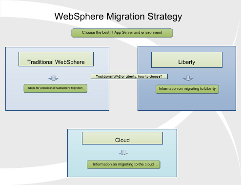
Target Version New Features PlanningTarget Version Potential ImpactsYour Current VersionProduct Documentation Target Version Planning Guide 7.08.0v8.5PlanningGuide v8.0PlanningGuide v8.5Planning Guide What s newv8.5What s newv8.0What s newv8.5Task 1 – Determine Your Migration Path What s Changed 8.5Special considerations:Migration from 6.0: If your current version of WebSphere Application Server is 6.0 and you wish to migrate to 8.5, you must first migrate to 7.0 or 8.0, then migrate from 7.0 or 8.0 to 8.5.Migration from 6.1: If your current version of WebSphere Application Server is 6.1 and you wish to migrate to 9.0, you must first migrate to 8.5, then migrate from 8.5 to 9.0.When choosing your target version take into account the features included in the new version and weigh up the benefits of migrating to the latest version to decrease how often a migration may be required.When skipping versions (for example migrating from v7 to v8.5) ensure you look at the What s New for each release you skip to ensure you know all the new features you will gain.Handling certain out of memory conditions when migrating, if you are migrating a large amount of applicationsTake a full system backup of your source before beginning the migrationBackWhat s Changed 8.5What s Changed 8.08.5What s newv9.0V9.0PlanningGuide What s Changed 9.0What s newv9.0V9.0PlanningGuide What s Changed 9.0What s Changed 9.0V9.0PlanningGuide What s newv9.0Liberty Liberty Migration InformationThe Liberty zero migration visionMaking the move to the Liberty Profile, Part 1Making the move to the Liberty Profile, Part 2Moving WebSphere and 3rd Party ApplicationsMoving Application BinariesConfiguration Scanning for migrationWebSphere Application Server – Migration Discovery ToolTotal Economic Impact of Migration From Open Source ApplicationServers to IBM WAS LibertyNotes :The Liberty product does not have a specific tool as traditional WebSphere has to migrate your configuration from one version to another. A combination of the tools listed above will assist you with moving your configurations and/or applications from WebSphere and/ or 3rd Party products to a Liberty Installation.BackCloud Cloud Migration Path Back Choose the best fit App Server and environmentCalculate savings on the Cloud using IBM WebSphereMoving WebSphere and 3rd Party ApplicationsMoving Application BinariesWAS Liberty in the cloudWebSphere Application Server v9 Update: On Premise and In theCloud - videoWebSphere on Cloud T otal C ost of O wnership CalculatorWebSphere Application Server – Migration Discovery ToolWebSphere Configuration Migration Tool for IBM Cloud - OverviewWebSphere Configuration Migration Tool for IBM Cloud - DownloadTarget VersionGeneral Migration Considerationsv8.5Preparing for Migration v8.0Preparing for Migration Task 2 – Preparing for your migrationPlanning Migration Type ConsiderationsBackMore information about planningfor a migrationv7.0Preparing forMigration V9.0Preparing for MigrationExecution Task 1 – Installation Download the appropriate versionfrom IBM Passport Advantage (orobtain media) for runtime andtoolkitPerform Installation v8.5 Target Environment Installation Guide v8.0 Target Environment Installation Guide Notesv8.0,v8.5 and v9.0 require the InstallationManager to install. Use the latest versionof the Installation Manager rather than theone delivered with the binaries.If you are performing a local migration, besure to change the WebSphere file pathsfrom the defaults during installation.Ensure that you follow all relevantinstructions for setting up the targetenvironment for your migration, found atthe links to the left.Verify that on a Unix target machine theulimit setting for the number of open files isset to 10000 or higher, unlimited ifpossible. To see the current setting runfrom the command lineulimit -a Backv7.0 Target Environment Installation Guide Image Numbersfor v8.0Image Numbers for v8.5.5Image Numbers for v9.0V9.0 Target Environment Installation GuideTask 2a – Migration to 7.0Migrating to WebSphere 7.0Migrating a standaloneappserver Migration using command line remote Migration using commandRollbackMigrationMigrating a Network Deployment ManagerLocal Remote Local Remote Migration using the Wizard Migration using command line Migration usingthe Wizard remote Migration using commandTask 2b – Migrating to 8.0Migrating to WebSphere 8.0Migration using command line remote Migration using commandRollbackMigrationMigrating a standaloneappserver Migrating a Network Deployment ManagerLocal Remote Remote Local remote Migration using commandMigration using the Wizard Migration usingthe Wizard Migration using command lineTask 2c – Migration to 8.5Migrating to WebSphere 8.5Migration using command line remote Migration using commandRollbackMigrationMigrating a Network Deployment ManagerMigrating a standaloneappserver Remote Remote Local Local Migration using the Wizard remote Migration using commandMigration using command line Migration usingthe WizardUseful Links。
Imperva WAF 技术白皮书

Imperva WAF 技术概述Imperva SecureSphere 概述 (2)部署拓扑 (3)部署选项 (3)安全引擎 (3)透明检测 (4)透明检测架构 (5)透明检测概览 (5)全面的应用程序感知 (7)会话保护 (8)网络和平台攻击保护 (8)URL 特征 (8)I MPERVA S ECURE S PHERE 概述传统的防火墙,在发挥重要作用的同时,却无法解决以上任何问题。
防火墙能够提供广泛的网络安全防护,有时还能够提供基本的应用程序感知,但缺乏认识或保护应用程序及其数据的能力。
对这些威胁的防护需要更高级别的认识- 在应用程序行为层。
SecureSphere®系统专门针对这一问题进行了开发,从而提供了该级别的保护。
应用程序行为层-OSI及其上层SecureSphere 系统的保护分布在近似OSI 7 层模型的多个层面上。
防火墙对应OSI 的第2 到第4 层,协议验证和应用程序层特征码类似于OSI 第7 层,如下图所示。
但是,多个SecureSphere 的高级保护进程(例如:特征评估、Web/数据库关联和关联攻击检测)面向应用程序的行为,相当于第8 层,该层未在OSI 模型中定义。
图2.1:应用程序行为层-位于OSI 模型之上中心管理SecureSphere 系统的MX 管理服务器是三层管理架构的中心点,允许组织机构同时自动管理多个网关。
安全策略是集中式管理,因此只需单击一下鼠标,就可以自动下发到多个网关。
MX 可用于各种任务,例如:配置管理、告警汇聚、分析及浏览、审计分析、报告、系统事件搜集等等。
部署拓扑SecureSphere®网络架构同时支持非在线网关(嗅听)和在线网关。
在线网关的侵入性强一些,但具有更好的阻止能力。
嗅听网关是完全非侵入式的,不能提供较为可靠的阻止能力(即:TCP 重置)。
部署选项SecureSphere®系统支持以下部署模式:❍在线拓扑如果要为数据中心提供最高级别的安全性保护,则可以将SecureSphere 网关部署为在线模式。
Websphere 8 for linux 集群配置
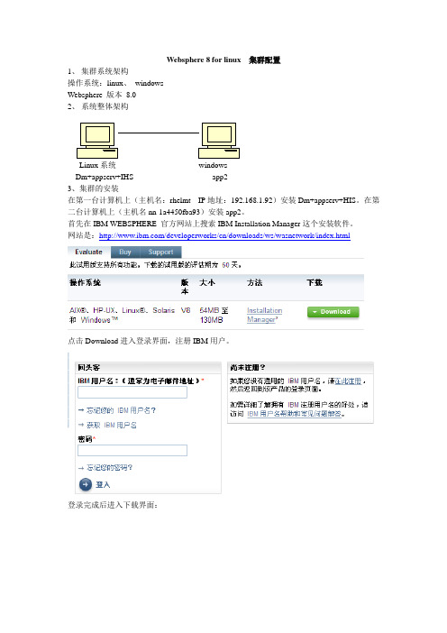
Websphere 8 for linux 集群配置1、集群系统架构操作系统:linux、windowsWebsphere 版本8.02、系统整体架构Linux系统windowsDm+appserv+IHS app23、集群的安装在第一台计算机上(主机名:rhelmt IP地址:192.168.1.92)安装Dm+appserv+HIS。
在第二台计算机上(主机名nn-1a4450fba93)安装app2。
首先在IBM WEBSPHERE 官方网站上搜索IBM Installation Manager这个安装软件。
网站是:/developerworks/cn/downloads/ws/wasnetwork/index.html点击Download进入登录界面,注册IBM用户。
登录完成后进入下载界面:选择上图所示选项,并单击“继续”按钮。
选择我同意并单击“我确认按钮”。
选择“使用HTTP下载”linux系统选择下面的选项:Windows系统选择下面的选项单击“立即下载”,下载保存在电脑磁盘上。
Linux环境:将下载下来的解压包解压如下图所示:解压方法:如果是tar包在终端中运行如下命令:tar xzvf 解压包名.tar如果是zip包直接解压安装方法:在IBMIM_linux_x86文件夹下运行终端,运行命令:./install进入安装页面。
界面:输入值钱注册的IBM用户标识和密码;登录成功后出现如下界面:点击“下一步”出现如下界面:去掉这个选项得到下图:点击“下一步”选择“我接受此协议中的条款”点击“下一步”自由选择几项答案,一直点击“下一步”出现如下界面:点击“安装”,等待安装完成,启动概要管理工具,点击“新建”在第一台计算机上(主机名:rhelmt IP地址:192.168.1.92)上新建一个Dm,选择“管理”点击“下一步”,选择“Deployment Manager”选择“应用程序服务器”,点击“下一步”选择“典型概要文件创建”,点击“下一步”程序服务器时要用到)点击“下一步”出现如下界面:记住各个端口号,后面配置要用到,点击“创建”出现如下界面:点击“完成”验证是否安装成功点击“安装验证”出现如下界面:至此安装完成。
norton partitionmagic 8.0

norton partitionmagic 8.0Norton PartitionMagic 8.0 – Simplifying Disk Partitioning and ManagementIntroduction:In the world of computer storage, efficient disk partitioning and management play a crucial role in ensuring optimal performance and organization of data. Norton PartitionMagic 8.0, a revolutionary software developed by Symantec, offers a robust solution to simplify disk partitioning and management tasks. This comprehensive software provides a range of features and functionalities to effortlessly partition, resize, and manage hard drives, making it a valuable tool for both personal and professional use.Key Features and Functionality:1. Partition Creation and Resizing:Norton PartitionMagic 8.0 allows users to create new partitions on their hard drives, enabling them to efficiently allocate space for different data types. It supports various file systems, including FAT, FAT32, NTFS, Ext3, and Linux Swap, providing flexibility in partition creation. Additionally, the software offers intuitive resizing features, enabling users toeasily extend or shrink existing partitions without any data loss.2. Error-Free Partitioning:Ensuring error-free partitioning is crucial to protect data integrity. Norton PartitionMagic 8.0 incorporates advanced algorithms and error-checking mechanisms to minimize the risk of data corruption during partitioning operations. The software detects potential errors and provides warnings, allowing users to take necessary precautions before making any changes to the partitions.3. Merging and Splitting Partitions:Managing multiple partitions can often be a challenging task. Norton PartitionMagic 8.0 simplifies this process by offering merging and splitting functionalities. Users can merge two adjacent partitions, combining the available space and creating a larger partition. Conversely, users can split a partition into two separate partitions, enabling them to better organize their data.4. Partition Conversion:With Norton PartitionMagic 8.0, users can easily convert partitions from one file system to another. This feature isparticularly useful when transitioning between different operating systems that require specific file systems. The software ensures a seamless conversion process while preserving data integrity.5. Boot Manager:The software comes equipped with a Boot Manager feature that allows users to have multiple operating systems installed on their machines. Users can select the desired operating system at system startup, making it ideal for dual-boot configurations or systems with multiple user profiles requiring separate operating systems.6. Data Backup and Recovery:Data loss can have catastrophic consequences, and it is essential to have a reliable backup and recovery mechanism in place. Norton PartitionMagic 8.0 includes a built-in backup and recovery feature, enabling users to create backups of their partitions and restore them in case of accidental data deletion or system failures.Conclusion:Norton PartitionMagic 8.0 is a powerful and user-friendly software that simplifies disk partitioning and managementtasks. Its intuitive interface, comprehensive features, and robust error-checking mechanisms make it a valuable tool for both beginners and advanced users. Whether it's creating new partitions, resizing existing ones, converting file systems, or managing multiple operating systems, Norton PartitionMagic 8.0 provides a seamless and reliable solution. By streamlining disk partitioning and offering data backup and recovery capabilities, it ensures efficient storage management and data protection in computer systems.。
LPC55Sxx系列处理器的TrustZone和Secure GPIO功能说明说明书

1背景LPC55Sxx(带有TrustZone 功能)具有Secure GPIO 模块,其使用与普通GPIO、TrustZone 和Secure AHB Controller 密切相关。
本节简要介绍这些功能。
有关更多信息,请参阅用户手册(User Manual)。
1.1TrustZone 和Secure AHB Controller1.1.1TrustZoneArmv8-M 的 TrustZone 可用于保护安全资源免受恶意代码的侵害。
安全资源包括安全存储器(代码/数据)和安全外围设备。
它是通过将地址空间分割成安全(S)或非安全(NS)来实现的。
TrustZone 可以根据分配给该地址空间的特定安全属性(S,NS)过滤来自 CPU0 的地址访问。
如 图 1 所示,安全状态下的 CM33 CPU(CPU-S)可以执行来自安全存储器(S-memory)的指令,但不允许直接从非安全存储器(NS-memory)执行指令。
然而,CPU-S 可以访问 S-内存和 NS-内存中的数据。
CPU-NS 只能从 NS-memory 执行指令,不允许从 S-memory 执行指令。
CPU-NS 只能在 NS-memory 中访问数据,不允许从 S-memory 访问数据。
图 1.信任区的安全状态和非安全状态视图综上:•非安全(NS)的应用程序“信任”安全的代码(secure code)不会无意中损坏/修改NS 代码或数据,或故意造成故障或危险。
•安全(S)的应用程序代码不“信任”非安全(NS)的应用程序代码,不允许CPU-NS 的访问。
目录1背景.................................................12Secure GPIO,Secure GPIO Mask 和Secure PINT...............................33用法.................................................54示例.................................................75结论. (9)6修订记录 (9)AN12326Secure GPIO 和使用方法版本 1 — 2020 年 2 月 26 日应用笔记1.1.2 Secure AHB ControllerLPC55Sxx(带有 TrustZone)使用 Secure AHB Controller 实现第二层保护,以在系统级别上提供安全执行。
SPARC T8 系列服务器安全指南说明书

如果将本软件或相关文档交付给美国政府,或者交付给以美国政府名义获得许可证的任何机构,则适用以下注意事项:
U.S. GOVERNMENT END USERS: Oracle programs, including any operating system, integrated software, any programs installed on the hardware, and/or documentation, delivered to U.S. Government end users are "commercial computer software" pursuant to the applicable Federal Acquisition Regulation and agency-specific supplemental regulations. As such, use, duplication, disclosure, modification, and adaptation of the programs, including any operating system, integrated software, any programs installed on the hardware, and/or documentation, shall be subject to license terms and license restrictions applicable to the programs. No other rights are granted to the U.S. Government.
websphere8.5安装手册(完整操作以及简单优化)

Websphere8.5安装部署规范2017年07月目录1 WEBSPERE8.5 64位安装 (3)1.1 介质 (3)1.2 安装环境 (3)1.3 部署前准备 (3)1.4 安装程序 (4)1.4.1 Installation Manager的安装 (4)1.4.2 WAS 的安装 (7)1.4.3 新建节点 (18)1.5 设置 (22)1.5.1 开启高速缓存 (22)1.5.2 JVM设置 (23)约定:✓要求所有软件均安装在/data目录下。
✓所有中间件安装后,不可关闭日志记录功能,日志文件确保至少是半年以上的日志记录。
1Webspere8.5 64位安装1.1介质介质下载地址:ftp介质软件名称版本Websphere8.5 64位WAS8501_allplatform.part1.rarWAS8501_allplatform.part2.rarV8.5JDK WAS8_SDK1.7.zip Jdk1.7 其他agent.installer.linux.gtk.x86_64_1.6.2000.20130301_2248.zip1.2安装环境规格参数服务器型号64位操作系统CENTOS 6.9内存4G1.3部署前准备一、在/data/soft下新建websphere安装包解压文件[root@redhat64 ~]# cd /data/soft/[root@redhat64 soft]# mkdir websphere8.5[root@redhat64 soft]# mkdir install[root@redhat64 soft]# mkdir sdk二、上传安装文件将WebSphere的安装包和补丁包上传到/data/soft/目录下:三、确认服务器已安装了firefox浏览器、linux版本的rar和zip解压工具。
四、Websphere只能使用自带的jdk。
1.4安装程序一、赋可执行权限并解压缩安装包[root@localhost ~]# cd /data/soft/[root@localhost soft]# chmod 775 *[root@localhost soft]# unzipagent.installer.linux.gtk.x86_64_1.6.2000.20130301_2248.zip -d intall/ [root@localhost soft]# unzip WAS8_SDK1.7.zip -d sdk/[root@localhost soft]# unrar x WAS8501_allplatform.part1.rar websphere8.5/1.4.1Installation Manager的安装[root@localhost soft]# cd intall/[root@localhost intall]# ./consoleinst.sh输入“N”,回车输入“A”,回车输入“N”,回车输入“L”,按回车,修改存放路径为“/data/IBM/InstallationManager/eclipse”,回车输入“N”,回车输入“I”,开始安装,等待安装完成,输入“R”重启Install Manager。
8.0安全(S12XS9SECV2)

安全(S12XS9SECV2)7.1.5 Unsecuring微控制器Unsecuring的可以通过三种不同的方法进行微控制器:1。
后门的主要通道2。
重整安全位3。
完整的内存删除(特殊模式)7.1.5.1 Unsecuring MCU的使用后门密钥访问在正常模式(单芯片和扩大),安全性,可以暂时禁用利用后门访问方法的关键。
此方法要求:•在0xFF00的后门钥匙0xFF07(=全局地址0x7F_FF00 - 0x7F_FF07)已被编程为有效的值。
•在KEYEN [1:0]在Flash选项比特/安全字节选择'支持'。
•在单芯片模式,应用程序编程到微控制器的设计必须有能力写信给后门关键地点。
后门自己的核心价值通常不会存储在应用程序数据,这意味着应用程序都必须用来接收从外部源的后门键值(通过串行端口,例如)。
关键的后门进入调试方法允许有担保微控制器无需擦除闪存。
这是特别有用的故障分析。
注意没有后门,关键是允许有值0x0000或0xFFFF的。
7.1.6重整安全位在正常的单芯片模式(NS)的,安全也可以禁用擦除和重新编程闪存的选择范围内的安全比特/安全字节的无担保的价值。
由于擦除操作将删除从0xFE00整个部门0xFFFF的(0x7F_FE00 - 0x7F_FFFF),后门键和中断向量也将被删除,这个方法是不正常的单芯片模式的建议。
应用程序软件只能擦除和编程的Flash选项/安全字节的闪存部门,如果包含闪光选项/安全字节得不到保障(见闪存保护)。
因此,闪存保护是防止这种方法的一个有用的手段。
微控制器后,将进入下一个不安全的状态重置以下保安位编程,无担保的价值。
此方法要求:•以前的应用软件编程到微控制器的设计有能力擦除和编程的Flash选项/安全字节或安全第一伤残人士在使用后门的主要方法,使BDM 用来发出命令的擦除和编程在Flash选项/安全字节。
•闪存部门的载有闪光选项/安全字节得不到保障。
WebSphere Application Server for z OS V8.0 概述与演示(适

B8ACRU
B8DMGRS STC16346 SYSA 0.02 141T 0.00 0.00 1360.8 00E5 OPS_DEF 0.04 16632881 BBOSR B8DMGRS
B8ASRU
B8SR01A STC18654 SYSA 0.07 109T 0.00 0.00 1610.8 0100 OPS_DEF 0.07 3284531 BBOCTL B8SR01A
Then point to the file in the “Response File” field of the window where you gave the
definition a name
Then just tab through the PMT windows and generate the jobs
Cell name (short)......: B8CELL Cell name (long).......: b8cell
Node name (short)......: B8NODEA Node name (long).......: b8nodea
Defined using the ISPF dialogs Long Name
Spreadsheet …
10/01/12
WAS V8 for z/OS Introduction, Copyright IBM Corp, 2012
5
Techdoc PRS4686: WAS V8 Planning Spreadsheet
An Excel spreadsheet that makes planning values and using the PMT much easier … it helps enforce a disciplined “top down” design:
WebSphere 应用服务器环境搭建实践指南
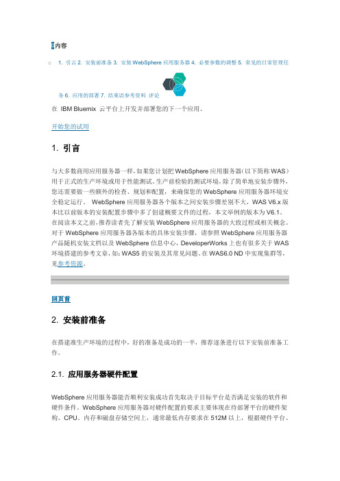
0内容o 1. 引言2. 安装前准备3. 安装WebSphere应用服务器4. 必要参数的调整5. 常见的日常管理任务6. 应用的部署7. 结束语参考资料评论WebSphere应用服务器版本、组件的不同,要求的配置也会略有区别,请参考WAS详细系统需求。
磁盘空间的分配请参见“2.4 确认磁盘空间是否满足要求”。
2.2. 确认操作系统版本是否满足要求作为一个成熟的商用应用服务器,WebSphere应用服务器会定期发布不同WAS版本(例如WAS V5.0, WAS V5.1,WAS6.0…)、组件(例如:Application Server, Edge Component)支持的操作系统版本信息。
使用WebSphere服务器支持的操作系统平台,能确保应用服务器安装、使用过程中环境的正常稳定运行。
尤其要注意的是,如果操作系统平台不是IBM WebSphere应用服务器官方支持的平台,在WebSphere应用环境出现问题后则无法获得WebSphere应用服务器的售后支持,更谈不上解决问题了。
例如,在笔者写这篇文章时,在x86芯片上,对于RedHat AS 4操作系统,如果要安装WebSphere应用服务器V6.1的Application Server组件,则要求的操作系统版本是Red Hat Enterprise Linux AS, Version 4 with Update 2。
如果您的操作系统版本是Red Hat Enterprise Linux AS, Version 4,则还需要安装Update2,否则有可能遇到问题。
由于支持的操作系统版本是定期更新的,请在搭建WebSphere应用服务器环境前,参照系统详细需求去查看当前操作系统版本(版本要与网上列出的完全一致)是否满足WebSphere应用服务器要求。
2.3. 确认网络配置/主机名满足要求在安装WebSphere应用服务器过程中,创建概要文件这一步骤需要用户填入机器的主机名(如图1),并且,WAS运行时也需要用到主机名(Host Name)。
- 1、下载文档前请自行甄别文档内容的完整性,平台不提供额外的编辑、内容补充、找答案等附加服务。
- 2、"仅部分预览"的文档,不可在线预览部分如存在完整性等问题,可反馈申请退款(可完整预览的文档不适用该条件!)。
- 3、如文档侵犯您的权益,请联系客服反馈,我们会尽快为您处理(人工客服工作时间:9:00-18:30)。
8.0 ADMIN Training Content
Admin
Lesson 1: Introduction to SecureSphere
Lesson 2: The Management GUI Lesson 3: Modeling the Datacenter Lesson 4: Detailed Site Tree Configuration Lesson 5: Global Objects Lesson 6: Introduction to Policies Lesson 7: Archiving and Actions
When it’s all over…
Share your contact information – Network
Respond to Class Survey – We read them!
Return for more: Database Security & Complg
Lesson 8: Universal User Tracking
Questions?
SecureSphere WAF Training Schedule
4-Day course 9:00 AM – 4:30 PM 2 morning breaks Lunch 2 afternoon breaks
Your Instructor:
Imperva Professional Services Real-World experience Part-time Implementer Part-time Consultant Part-time Trainer Multiple years of security-related experience
Facilities:
Break Room Restrooms Drinks and Snacks Food/Drinks in Classroom? Lunch When Where How
Common Courtesy:
Disable ringers and noisy email notifications Quietly excuse yourself from the room if you must answer a call or remotely work an issue You are here for a reason – actively participate Respect your neighbor
Lesson 8: Alerts and Monitoring
Lesson 9: Reporting Lesson 10: Administration
Lesson 11: Imperva Services
WAF Administration
8.0 Web Application Firewall Training Content
Imperva WAF Training: Web Application Firewall
Course Overview
Consultant-led instruction Hands-on lab experience Generate traffic and perform attacks Observe first-hand how SecureSphere learns, monitors and protects resources Focus on the practical skills needed to configure, protect and maintain SecureSphere
Admin
WAF Administration
Lesson 1: Web Server & Service Discovery Lesson 2: Web Dynamic Profiling Lesson 3: Advanced Web Policies Lesson 4: ThreatRadar Lesson 5: Web Tagging and Data Enrichment Lesson 6: Web Vulnerability Management
Industry Certifications
Your Classmates:
Diverse Group of Professionals Compliance Officers Firewall Administrators WEB Developers Database Administrators Security Consultants Penetration Testers Decision Makers & Architects Complement your neighbor’s skill set Don’t be afraid to ask questions
