保时捷维修手册:996_TI_3c
保时捷维修手册:987_TI_Tequc2
2 Cayman (987)
1/05 ZH 2005
车辆类型: 情况:
Cayman S 改装
注释:
燃油箱盖(“Tequipment”目录中的“铝制外观燃油箱盖”)可用于上面提到的车辆 ⇒ 看图像。
带有 Porsche 徽标、5 个卡孔和 6 个六角凹头螺栓的燃油箱盖类似于传统赛车的燃油箱 盖设计。
“铝制外观燃油箱盖”只能在经过授权的 Porsche 服务中心进行装配!
⇒ 997.044.200.05 ⇒ 999.507.499.40 ⇒ 996.006.118.01
图2
1 x 燃油箱盖 ⇒ 图 2 -A1 x Cayenne 防失器,尺寸 X 约 130 mm 长 ⇒ 图 2 -B- 包括预装的卡
子 ⇒ 图 2 -C1 x 跑车防失器,尺寸 X 约 210 mm 长 ⇒ 图 2 -D1 x 跑车膨胀铆钉: 直径约为 5.0 mm ⇒ 图 2 -E1 x 标签(警告注释);仅适用于 Cayenne ⇒ 图 2 -F-
1.1 将跑车防失器的环(正面在先)导入新 燃油箱盖的螺纹。
1.2 将环插入燃油箱盖螺纹上的槽 ⇒ 图 3 -B中。
1.3 用拇指将环压入槽 ⇒ 图 3 -C- 中,使环卡 入位。
图3
2 拆下旧的燃油箱盖。 2.1 打开车辆上的油箱盖(请参见《驾驶员
手册》)。 2.2 使用 芯轴,Ø = 2.5 mm 顶出膨胀铆钉销。 2.3 用通用钳从油箱盖上的孔中取下膨胀铆钉。
1x
跑车膨胀铆钉,Ø 约为 5.0 x 11.5 mm ⇒ 图 2 -E-
1x
标签(警告标志);仅适用于 Cayenne ⇒ 图 2 -F-
偏口钳
危险 意外事故的危险(死亡/人身伤害) • 由于燃烧和/或爆炸 ⇒ 必须严格禁止烟雾、明火和飞溅的火花! ⇒ 要戴防护手套和护目镜! ⇒ 操作燃油系统时应遵守常规安全规定!
2010 911中文维修手册
2010 911中文维修手册一、概述2010年发布的911是保时捷汽车公司的一款具有里程碑意义的车型,它融合了现代科技和经典设计,成为了汽车界的一大亮点。
保时捷911车系因其卓越的性能和可靠的质量而备受全球车迷的喜爱,而911中文维修手册的问世更是极大方便了我国地区的车主和维修人员。
二、911中文维修手册的重要性1. 丰富的内容911中文维修手册详细介绍了此车型的结构、原理、维修方法和注意事项,对整车的每个部件、系统和功能都进行了清晰而全面的描述,使车主和专业维修人员能够深入了解和掌握其维修知识。
2. 提高维修效率有了911中文维修手册,维修人员可根据手册内容第一时间找到问题的所在,了解修理的难易程度和耗时程度,为维修过程提供了有力的帮助,提高了维修效率。
3. 确保维修质量手册中包含了品牌冠方认证的技术维修指南,依据最新的维修工艺和标准进行维修操作,能够准确诊断和解决车辆问题,保障维修质量。
三、911中文维修手册的特点1. 全面性911中文维修手册对车辆的机械结构、电气系统、车辆诊断、维修保养等方面进行了全面而深入的介绍,涵盖了车辆的各个系统和维修细节。
2. 高清晰度手册中的图片和图表经过细致处理和编辑,清晰度高,能够让读者一目了然地了解车辆的结构和维修细节,尤其对于维修人员来说,是一份宝贵的参考资料。
3. 实用性911中文维修手册由专业技术团队编写审核,内容准确可靠,操作性强,具有实用性和可操作性。
四、911中文维修手册的更新和持续优化1. 更新频率保时捷公司会根据车型的升级和变化情况,时刻关注车主和维修人员的反馈和需求,不断对维修手册进行更新和完善,确保手册始终与车型保持同步。
2. 客户需求保时捷公司注重客户需求,积极倾听车主和维修人员的建议和意见,不断对维修手册进行持续优化,以满足用户的多样化需求。
五、结语911中文维修手册的推出对于我国地区的车主和维修人员而言无疑是一大利好消息,它不仅方便了车主的日常保养和维修,也提升了维修人员的专业水平。
保时捷车型维修指南说明书
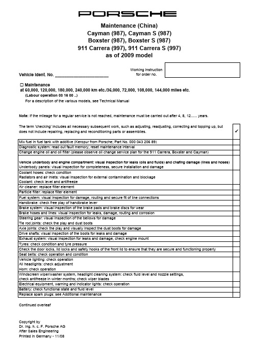
Vehicle Ident. No. _______________________Working instruction for order no.! Maintenanceat 60,000, 120,000, 180,000, 240,000 km etc./36,000, 72,000, 108,000, 144,000 miles etc.(Labour operation 03 16 00 ..)For a description of the various models, see Technical Manual Mix fuel in fuel tank with additive (Keropur from Porsche; Part No. 000 043 206 89)The term 'checking' includes all necessary subsequent work, such as adjusting, readjusting, correcting and topping up, but does not include repairing, replacing and reconditioning parts or assemblies.Change engine oil and oil filter (please observe oil change service plan for the 911 Carrera, Boxster and Cayman)"Note: If the mileage for a regular service is not reached, maintenance must be carried out after 4, 8, 12...... years.911 Carrera (997), 911 Carrera S (997)Boxster (987), Boxster S (987)as of 2009 modelDiagnostic system: read out fault memory; reset maintenance intervalVehicle underbody and engine compartment:visual inspection for leaks (oils and fluids)and chafing damage (lines and hoses)Continued overleaf Copyright byElectrical equipment, warning and indicator lights: check operationVehicle lighting: check operationAll headlights: check adjustmentHorn: check operationHandbrake: check free play of handbrake leverExhaust system: visual inspection for leaks and damage, check engine mountBrake hoses and lines: visual inspection for leaks, damage, routing and corrosionSteering gear: visual inspection of the bellows for damageTie rod joints: check the play and dust bootsSeat belts: check operation and conditionAir cleaner: replace filter elementFuel system: visual inspection for damage, routing and secure fit of line connectionsParticle filter: replace filter elementDrive shafts: visual inspection of the boots for leaks and damageBrake system: visual inspection of the brake pads and brake discs for wearTyres: check condition and tyre pressureCheck the door locks, lid locks and safety hooks of the front lid to ensure that they are secure and functioning properly Axle joints: check the play and visually inspect the dust boots for damageVehicle underbody and engine compartment: visual inspection for leaks (oils and fluids) and chafing damage (lines and hoses)Underbody panels: visual inspection for completeness, secure installation and damageCoolant hoses: check conditionRadiators and air inlets: visual inspection for external contamination and blockageCoolant: check level and antifreezeWindscreen wiper/washer system, headlight cleaning system: check fluid level and nozzle settings,check antifreeze in winter months; check wiper bladesReplace spark plugs: see Additional maintenanceBattery: check functional state and fluid levelpy g y Dr. Ing. h. c. F. Porsche AGAfter Sales EngineeringPrinted in Germany - 11/08Vehicle Ident. No. _______________________Working instruction for order no.! Additional maintenance for spark plugs(Labour operation 03 81 00 ..)"! Additional maintenance for drive belt (Labour operation 03 60 00 ..)! Additional maintenance for convertible top(Labour operation 03 70 00 ..)! Additional maintenance every 90,000 km/54,000 miles or every 6 years (Labour operation 03 83 00 ..)as of 2009 modelService and maintain convertible top (911 Carrera only)every 30,000 km/18,000 miles or every 2 years Replace spark plugs every 30,000 km/18,000 miles or every 4 years Check drive belt every 60,000 km/36,000 miles or every 4 years every 150,000 km/90,000 miles or every 10 years Check drive beltCheck drive belt every 240,000 km/144,000 miles or every 16 years Boxster (987), Boxster S (987)R l d i b lt911 Carrera (997), 911 Carrera S (997)Controlled all-wheel (only Carrera 4) : change oil! Additional maintenance every 180,000 km/108,000 miles or every 12 years(Labour operation 03 88 00 ..)! Every 2 yearsFile condition report for long-life guarantee! Every 4 years! After 4 years, then every 2 years! After 4, 8, 10 years, then every 2 yearsSignature (mechanic): _______________________________Test drive:Oils, fluids: visual inspection for leaksSignature (final check): _________________________Remote control, front seats, footbrake and handbrake (also actuation travel), engine, clutch, steering, transmission, ParkAssist, cruise control, PSM switch, PASM switch, Sport switch, heating, air conditioning and instruments: check operation Manual transmission: change oilAncillary unit mounts and suspension: visual inspection of all rubber mountings and boots for damageChange brake fluidReplace tyre sealantCheck tyre pressure monitoring system batteryPDK transmission: change clutch fluidReplace drive belt PDK transmission: change transmission oilAll-wheel final drive: change oil (911 Carrera only)Copyright byDr. Ing. h. c. F. Porsche AGAfter Sales EngineeringPrinted in Germany - 11/08Porsche Centre。
保时捷用户手册

车窗和滑动式天窗 .......................... 71
电动车窗 ....................................................72 可倾 / 滑动式天窗 .......................................75 全景式天窗 .................................................76 可倾 / 滑动式天窗或全景式天窗的 紧急操作 ....................................................80
驾驶手册中的安全指南
本驾驶手册中包含各种类型的安全指南。
h 危险
Porsche、保时捷盾徽、 Cayenne、 PCCB、 PCM、 PSM、 Tiptronic 和 Tequipment 均为 Dr. Ing. h.c. F. Porsche AG (保时捷股份公司) 的注册商标。 中国印刷。 未经 Dr. Ing. h.c. F. Porsche AG (保时捷股份公司) 书面授权,不得翻印、摘录或复印本手册。 © Dr. Ing. h.c. F. Porsche AG Porscheplatz 1 D-70435 Stuttgart
建议
如果对车辆或本行车参考文件有任何疑问、建议 或想法,请致函以下地址: Dr. Ing. h.c. F. Porsche AG Vertrieb Customer Relations Porschestrasse 15-19 71634 Ludwigsburg
可能导致中度或轻度的人身伤害。 未遵守 “ 小心 ” 中的安全指南可能导致中度或 轻度的人身伤害。
WKD 948 093 12
保时捷维修手册:996_TI_4c
1 不适用于墨西哥
2 仅适用于欧盟 (EU) 国家/地区,且不包括英国、希腊、荷兰和瑞典。
标有“Rotation”(旋转)字样的箭头
“Inside/Outside”(内侧/外侧)标记
© Dr. Ing. h.c. F. Porsche AG Printed in Germany
2006-4-11 页 8 of 12
4 911 (996) 4440 ZH 1/06
车轮:
Porsche 夏季轮胎车轮概述
车轮轮盘内侧/外侧上的标识: 车轮尺寸,轮辋偏移量 (RO) (mm)、零件号和 Porsche 徽标
危险 轮胎压力不足和/或受损轮胎。 • 事故危险增加 ⇒ 轮胎压力决不能低于下面所示的轮胎压力。 ⇒ 定期检查轮胎,查看形状磨损是否均匀,是否存在可能的损坏,如破裂、鼓起、胎面分层、异物等。 ⇒ 不要对轮胎使用溶剂或其他化学物质(例如清洗或染色)。
2006-4-11 页 5 of 12
© Dr. Ing. h.c. F. Porsche AG Printed in Germany
调整后裙板
如果后裙板超出了用法兰连接的后侧部(切 口 A),则切掉或磨掉后裙板的超出部分 (箭头)。
翼子板接缝
垫圈
固定垫圈和车轮(标准的 911 GT3)
作为标准配置,911 GT3 附带 5 mm 厚的垫圈。 这些垫圈是使用沉头螺钉 (M6 x 16)(零件 号 900.269.106.09)与制动盘一起固定在 轮毂上的。 拧紧力矩 10 Nm 安装备胎之前,5-mm 的垫圈必须仍然固定 在车辆上。
波士德汽车 (Porsche) 维修指南说明书
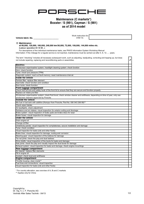
Work instruction fororder no.☐ Maintenance(Labour operation 03 16 00 ..)Check front lid lock and safety hook of the front lid to ensure that they are secure and function properlyDrain engine oilUnderbody panels: visual inspection for completeness, secure installation and damageWindscreen wiper/washer system: check fluid level; check window cleaner and antifreeze, depending on time of year, only use windscreen cleaners approved by PorscheUnder the vehicle* For country allocation, see overview of A, B and C marketsOutside the vehicleFill in engine oilVisual inspection for leaks (oils and other fluids)Brake system: visual inspection of brake pads and brake discs for wearBrake hoses: visual inspection for damageAll headlights: check adjustment** Applies only for ChinaAir cleaner: replace filter elementsThrottle housing: clean inside**For descriptions of the individual maintenance tasks, see PIWIS Information System Workshop ManualSteering gear: visual inspection of the bellows for damageTie rod joints: check the play and dust bellowsDrive shafts: visual inspection of the boots for leaks and damageHorn: check functionat 60,000, 120,000, 180,000, 240,000 km/36,000, 72,000, 108,000, 144,000 miles etc.as of 2014 modelVehicle Ident. No. ______________________Door locks: check functionFront luggage compartmentSeat belts: check function and condition✓Information: If the mileage for a regular service is not reached, maintenance must be carried out after 4, 8, 12...... years.Tyres: check tyre pressure (TPM)The term "checking" includes all necessary subsequent work, such as adjusting, readjusting, correcting and topping up, but does not include repairing, replacing and reconditioning parts or assemblies.Windscreen wiper/washer system, headlight cleaning system: check functionBrake lines: visual inspection for damage, routing and corrosionExhaust system: visual inspection for leaks and damage, check engine mountingsVisual inspection for leaks (oils and other fluids)Tyres: check conditionParticle filter: replace filter elementReplace air intake pre-filterAxle joints: check the play and visually inspect the dust boots for damageEngine compartmentMix fuel in fuel tank with additive (Keropur from Porsche; Part No. 000 043 206 89)**Check wiper bladesCoolant: check level and antifreezeDiagnostic system: read out fault memory; reset maintenance intervalElectricsInside the vehicleBoxster / S (981), Cayman / S (981)Radiators and air intakes: visual inspection for exterior soiling and blockageChange oil filterRear luggage compartmentFuel lines and connections: visual inspectionWork instruction fororder no.☐✓☐ Additional maintenance for drive belt (Labour operation 03 60 00 ..)☐ (Labour operation 03 83 00 ..)☐Additional maintenance every 120,000 km/72,000 mls or every 4 years(Labour operation 03 85 00 ..)☐(Labour operation 03 88 00 ..)☐ (Labour operation 03 51 00 ..)Porsche CentreReplace spark plugs (Labour operation 03 81 00 ..)every 30,000 km/18,000 mls or every 4 years Check drive beltat 240,000 km/144,000 mls or every 16 years Check drive beltat 60,000 km/36,000 mls or every 4 years Check drive beltAdditional maintenance every 90,000 km/54,000 mls or every 6 yearsat 150,000 km/90,000 mls or every 10 years Replace drive belt Ancillary unit mounts and chassis: visual inspection of all rubber mountings and boots for damageAdditional maintenance every 180,000 km/108,000 mls or every 12 yearsEvery 2 yearsTyre sealing compound: Check use-by date and replace if necessaryManual transmission: change oilChange brake fluid (use only original Porsche brake fluid)Prepare condition report for long-life guaranteePDK transmission: change transmission oilPDK transmission: change clutch fluidSignature (mechanic): ____________________________Signature (final check): _________________________Boxster / S (981), Cayman / S (981)as of 2014 modelVehicle Ident. No. ______________________Additional maintenance for spark plugs。
保时捷 Panamera 中文说明书

Every 2 years (Labour operation 03 51 00 ..)
Change brake fluid (use only original Porsche brake fluid) Complete Condition Report for Long-Life Guarantee Clutch: Change brake fluid; perform test and adaptation (Panamera S E-Hybrid) Tyre sealing compound: Check use-by date and replace if necessary
Replace PDCC reservoir PDK transmission: Change oil (Panamera / S / GTS / Turbo) Turbo compressor: Replace drive belt (Panamera S E-Hybrid) Air cleaner: Replace filter element (Panamera / S / Turbo / Diesel / E-Hybrid) Air cleaner/additional air filter: replace filter elements (Panamera GTS)
Signature (final check): _________________________
Copyright by Dr. Ing. h.c. F. Porsche AG After Sales Engineering - 03/14
Porsche Centre
Additional maintenance every 240,000 km/144,000 mls or every 16 years (Labour operation 03 95 00 ..)
瑞麒G6维修手册——电路部分(更新10.02

保时捷各车型车主保养手册(,通用建议收藏)
第 1 任车主 (姓,名) 街道和门牌号码 城镇和邮政编码
第 2 任车主 (姓,名) 街道和门牌号码 城镇和邮政编码
第 3 任车主 (姓,名) 街道和门牌号码 城镇和邮政编码
第 4 任车主 (姓,名) 街道和门牌号码 城镇和邮政编码
第 5 任车主 (姓,名) 街道和门牌号码 城镇和邮政编码
第 6 任车主 (姓,名) 街道和门牌号码 城镇和邮政编码
1. 未将所购产品按规定用途使用或将其过度使用 (如赛车运 动中);
2. 所购产品曾接受过由未经保时捷股份公司认可具有相应能 力的公司提供的非专业维修或保养服务;
3. 将未经保时捷股份公司授权的零配件安装到所购产品、未 按保时捷股份公司要求或未按用途和说明使用燃油、润滑 油、机油和其他油、冷却液、清洁液和抛光液;
4. 所购产品按未经保时捷股份公司授权的方式进行了改装;
5. 购买者未遵守保时捷股份公司在 《驾驶手册》及 《保修和 保养手册》中有关所购产品的处理、保养和养护的说明;
6. 不可抗力 (包括自然灾害或暴动、战争、军事行动等)、 第三方的犯罪活动,或购买者的故意行为;
7. 购买者未能按要求立即报告故障或提供立即返修的机会。
每 2 年进行一次附加保养
更换制动液 完成长期质保车况报告 Panamera S E-Hybrid:更换离合器的制动液;执行测试和自适应 补胎胶:检查保质期,必要时更换
每 90,000 km 进行一次附加保养,且每 4 年至少进行一次
更换 PDCC 储液罐 Panamera (V6)、 Panamera 4、 Panamera S、 Panamera 4S、 Panamera GTS、 Panamera Turbo:Porsche Doppelkupplung (PDK) 保时捷双离合器变速箱:更换变速箱油 Panamera S E-Hybrid:更换增压器传动皮带 空气滤清器:更换滤芯
2013-2015保时捷帕拉梅拉Panamera 970维修手册
最新全套保时捷维修资料------寶馳名車中心语言language:中文Chinese Italiano English Français Deutsch Español Japan日本2014-2015保时捷Macan 95B维修手册2014-2015保时捷918 Spyder 维修手册2013-2015保时捷帕拉梅拉Panamera 970维修手册2010-2012保时捷帕拉梅拉Panamera 970维修手册2012-2015保时捷卡雷拉Carrera911 991维修手册2006-2010保时捷卡雷拉Carrera911 996 997维修手册2012-2015保时捷Boxster, Cayman 981维修手册2009-2012保时捷卡曼Cayman 987维修手册2009-2012保时捷博克斯特Boxster 987维修手册2011-2012年保时捷卡宴Cayenne 92A维修手册2013-2015年保时捷卡宴Cayenne 92A维修手册2008-2011保时捷卡宴Cayenne 9PA维修手册2004-2006保时捷卡宴Cayenne 9PA维修手册2011-2014保时捷全车型常用保养维修手册2010-2013保时捷全车型编码故障码数据流汇集2009-2014保时捷全车型故障代码查询诊断帮助老款保时捷Porsche911维修手册老款保时捷Porsche968维修手册保时捷Macan 95B电路图保时捷918 Spyder电路图保时捷帕拉梅拉Panamera 970电路图保时捷帕拉梅拉Panamera 970电路图保时捷卡雷拉Carrera911 991电路图保时捷卡雷拉Carrera911 996 997电路图保时捷Boxster, Cayman 981电路图保时捷卡曼Cayman 987电路图保时捷博克斯特Boxster 987电路图保时捷卡宴Cayenne 92A电路图保时捷卡宴Cayenne 9PA电路图2005-2012保时捷电路图系统WDS2005-2015保时捷电路图系统WDS技术培训:保时捷Macan多媒体课程保时捷Panamera 多媒体课程保时捷918 Spyder多媒体课程保时捷911 Carrera多媒体课程保时捷卡宴Cayenne多媒体课程保时捷Boxster多媒体课程保时捷Hybrid技术多媒体课程保时捷舒适性电气系统多媒体课程保时捷PIWIS II诊断编程操作多媒体保时捷动力传输系统多媒体课程保时捷发动机电气系统多媒体课程保时捷PDK双离合器变速箱多媒体课程2015保时捷MacanDiesel MacanS MacanTurbo 95B培训手册2015保时捷918Spyder技术培训手册2014保时捷培训中心技师培训课件2014保时捷帕拉梅拉Panamera970所有车型技术培训手册2014保时捷卡曼981 Cayman CaymanS技术培训手册2014保时捷卡雷拉Carrera911 991 GT3技术培训手册2014保时捷电器CAN波形高级培训资料2014保时捷Macan 95B技术培训手册2014保时捷918 Spyder技术培训手册2014保时捷911 GT3技术培训手册2014 年款保时捷981 Cayman Cayman CaymanS培训手册2013年保时捷卡雷拉911 991Carrera CarreraS技术培训手册2013保时捷全车型电器诊断技术高级培训资料2013保时捷培训中心技师培训课件2013保时捷帕拉梅拉970 Panamera技术培训手册2013保时捷卡宴92A Cayenne发动机电器系统技术培训2013保时捷卡宴92A CayenneS Diesel技术培训手册2013保时捷卡宴92A Cayenne CayenneS Diesel 培训手册2013保时捷卡宴92A Cayenne CayenneS CayenneTurbo技术培训手册2013保时捷卡曼981 Cayman CaymanS 技术培训手册2013保时捷卡雷拉911Carrera4 Carrera4S技术培训手册2013保时捷博克斯特981 Boxster BoxsterS技术培训手册2012保时捷中心在线车型技师高级培训课程2012保时捷培训中心卡宴92A Cayenne培训课件2012保时捷培训中心技师培训课件2012保时捷帕纳梅拉970 Panamera技术培训手册2012保时捷卡宴92A Cayenne S Hybrid混合动力技术培训手册2012保时捷卡宴92A Cayenne CayenneS CayenneTurbo培训手册2012保时捷卡雷拉Carrera Carrera S 991技术培训手册2012保时捷车型发动机技师培训课件2012保时捷911 Carrera CarreraS技术培训手册2011保时捷培训中心技师培训课件2011保时捷卡宴92A Cayenne技术培训手册2010保时捷帕纳梅拉970 Panamera技术培训手册2009保时捷卡宴9PA Cayenne 技术培训手册2009保时捷卡宴9PA Cayenne Diesel技术培训手册2009保时捷卡雷拉Carrera997技术培训手册2009保时捷卡雷拉Carrera911技术培训手册2009保时捷987 Boxster Cayman技术培训手册2008保时捷卡宴9PA Cayenne CayenneS培训手册2007保时捷卡宴9PA Cayenne培训手册2007保时捷911 Carrera CarreraS技术培训手册2006保时捷卡曼987 CaymanS技术培训手册2006保时捷卡雷拉911 Carrera4 Carrera4S培训手册2006保时捷987 CaymanS技术培训手册2005保时捷卡宴9PA Cayenne CayenneS CayenneTurbo技术培训手册2005保时捷987 Boxster技术培训手册2005保时捷911卡雷拉CarreraS技术培训手册2004保时捷卡宴Cayenne 技术培训手册保时捷传动系统技术培训--认证技师课程保时捷底盘技术培训--认证技师课程保时捷发动机技术培训--认证技师课程保时捷电子和电气技术培训--认证技师课程保时捷发动机电器技术培训--认证技师课程保时捷诊断仪PIWIS_II技术培训课程保时捷金银铜级技师考试资料汇集保时捷技师基础培训资料技术会议与案例研讨:2005年保时捷技术会议与案例研讨2006年保时捷技术会议与案例研讨2007年保时捷技术会议与案例研讨2008年保时捷技术会议与案例研讨2009年保时捷技术会议与案例研讨2010年保时捷技术会议与案例研讨2011年保时捷技术会议与案例研讨2012年保时捷技术会议与案例研讨2013年保时捷技术会议与案例研讨保时捷PPN技术信息寶馳名車國際服務中心Bao Chi Super luxury car International Service Center。
保时捷用户手册
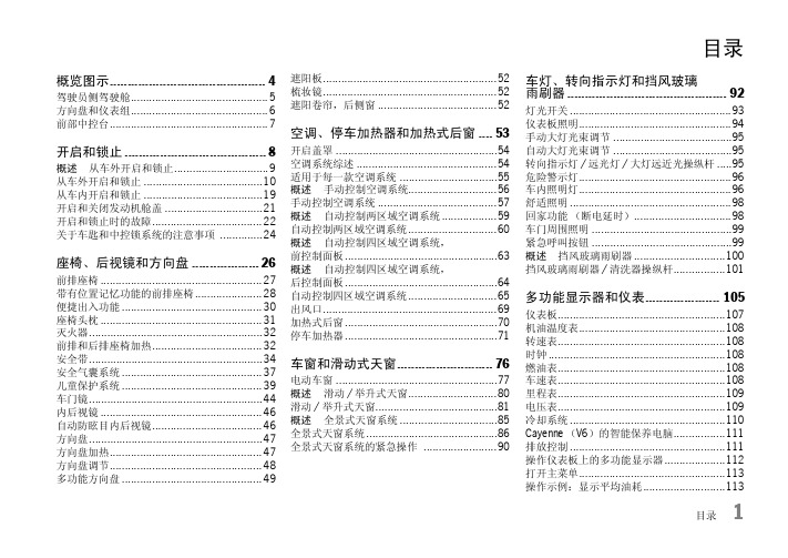
目录概览图示 (4)驾驶员侧驾驶舱 (5)方向盘和仪表组 (6)前部中控台 (7)开启和锁止 (8)概述 – 从车外开启和锁止 (9)从车外开启和锁止 (10)从车内开启和锁止 (19)开启和关闭发动机舱盖 (21)开启和锁止时的故障 (22)关于车匙和中控锁系统的注意事项 (24)座椅、后视镜和方向盘 (26)前排座椅 (27)带有位置记忆功能的前排座椅 (28)便捷出入功能 (30)座椅头枕 (31)灭火器 (32)前排和后排座椅加热 (32)安全带 (34)安全气囊系统 (37)儿童保护系统 (39)车门镜 (44)内后视镜 (46)自动防眩目内后视镜 (46)方向盘 (47)方向盘加热 (47)方向盘调节 (48)多功能方向盘..............................................49遮阳板 (52)梳妆镜 (52)遮阳卷帘,后侧窗 (52)空调、停车加热器和加热式后窗 (53)开启盖罩 (54)空调系统综述 (54)适用于每一款空调系统 (55)概述 – 手动控制空调系统 (56)手动控制空调系统 (57)概述 – 自动控制两区域空调系统 (59)自动控制两区域空调系统 (60)概述 – 自动控制四区域空调系统,前控制面板 (63)概述 – 自动控制四区域空调系统,后控制面板 (64)自动控制四区域空调系统 (65)出风口 (69)加热式后窗 (70)停车加热器 (71)车窗和滑动式天窗 (76)电动车窗 (77)概述 – 滑动/举升式天窗 (80)滑动/举升式天窗 (81)概述 – 全景式天窗系统 (85)全景式天窗系统 (86)全景式天窗系统的紧急操作 (90)车灯、转向指示灯和挡风玻璃雨刷器 (92)灯光开关 (93)仪表板照明 (94)手动大灯光束调节 (95)自动大灯光束调节 (95)转向指示灯/远光灯/大灯远近光操纵杆 (95)危险警示灯 (96)车内照明灯 (96)舒适照明 (98)回家功能(断电延时) (98)车门周围照明 (99)紧急呼叫按钮 (99)概述 – 挡风玻璃雨刷器 (100)挡风玻璃雨刷器/清洗器操纵杆 (101)多功能显示器和仪表 (105)仪表板 (107)机油温度表 (108)转速表 (108)时钟 (108)燃油表 (108)车速表 (108)里程表 (109)电压表 (109)冷却系统 (110)Cayenne(V6)的智能保养电脑 (111)排放控制 (111)操作仪表板上的多功能显示器 (112)打开主菜单 (113)操作示例:显示平均油耗 (113)目录1显示/复位平均车速 (115)显示剩余燃油可达里程 (115)显示轮胎气压 (115)显示罗盘 (115)显示导航信息 (115)通过多功能显示器操作电话 (116)在多功能显示器上设置限速 (117)显示警告信息 (118)显示水平高度控制状态 (119)显示锁止系统/越野档的状态 (119)显示平均油耗 (120)设置轮胎气压监控 (120)在多功能显示器上停用座舱监控和倾斜传感器 (129)车门镜同步调节 (129)改变车辆解锁和锁止设置 (130)设置延迟关闭 (132)设置时钟 (132)设置罗盘 (133)更改显示语言 (134)更改显示单位 (134)将显示复位到出厂设置 (134)警告信息综述 (135)驾驶和行驶安全 (144)开车之前 (145)磨合技巧 (145)回收利用 (146)技术改造 (146)点火锁/转向锁 (147)起动和关闭发动机 (149)手机和双向无线电通讯 (150)Porsche 通讯管理系统(PCM) (150)收音机.......................................................150停车制动器 (151)脚制动器 (151)巡航定速控制 (153)手动变速箱、离合器 (156)Tiptronic S (157)换档杆位置 (158)用于公路和越野驾驶的驾驶程序 (164)动力传输和底盘控制系统 (168)带有水平高度控制和高度调节的气动悬挂系统 (178)Porsche 主动悬挂管理系统(PASM) (181)Porsche 动态底盘控制(PDCC) (182)越野驾驶 (183)用于越野驾驶的行驶系统 (184)上坡道驾驶 (185)下坡道驾驶 (186)涉水驾驶 (187)跨越障碍物 (189)行李厢、装载区和储物空间 (191)向前折叠后排座椅及恢复到竖直位置 (192)装载区 (195)装载区管理系统 (196)装载 (199)行李厢盖 (200)行李安全网兜 (201)滑雪包 (203)车顶运输系统 (205)储物空间 (206)杯座 (209)右前座椅下面的 DVD 播放机 (211)烟灰缸,前排 (211)点烟器 (212)拖车钩 (213)拖车钩 (214)带有可拆卸球形连接器的拖车钩 (216)电动折叠拖车钩密封装置 (221)驻车 (223)停车辅助系统 (224)作为停车辅助功能向下转动后视镜玻璃 (228)车库开门装置 (228)防盗警报系统和防盗保护 (231)防盗警报系统 (232)防盗装置 (234)转向柱锁 (234)防盗保护 (234)保养和汽车养护 (235)保养注意事项 (236)检查机油油位 (237)添加机油 (238)检查冷却液液位及添加冷却液 (240)检查制动液液位及更换制动液 (242)洗涤液的添加 (243)更换空气滤清器 (244)更换微粒滤清器 (244)动力转向 (244)雨刷器刮片 (245)排放控制系统 (248)燃油罐 (248)加注燃油 (249)汽车养护说明 (251)2目录小修 (258)小修注意事项 (259)轮胎和车轮 (260)千斤顶 (266)工具包 (266)充气机 (267)厚垫片 (267)车轮螺栓 (268)轮胎漏气 (269)为不带水平高度控制系统的车辆上的轮胎充气 (279)为带有水平高度控制系统的车辆上的轮胎充气 (280)电气系统 (285)蓄电池 (293)更换遥控器电池 (296)外部电源,跨接起动 (297)更换灯泡 (299)大灯 (300)尾灯 (310)牌照灯 (312)大灯调整 (313)左侧通行改为右侧通行时的大灯切换 (313)灯泡规格表 (314)牵引和牵引起动 (315)轮胎气压和技术数据 (319)车辆识别数据 (320)发动机技术数据 (321)变速箱 (322)燃油油耗 (322)轮胎、车轮、轮距 (323)轮胎气压,冷态.........................................326重量. (328)离地间隙 (329)容积 (331)尺寸 (332)行驶性能 (333)索引 (334)目录3概览图示驾驶员侧驾驶舱 (5)方向盘和仪表组 (6)前部中控台 (7)4概览图示概览图示5驾驶员侧驾驶舱1.电动车窗见第77页。
捷豹维修手册
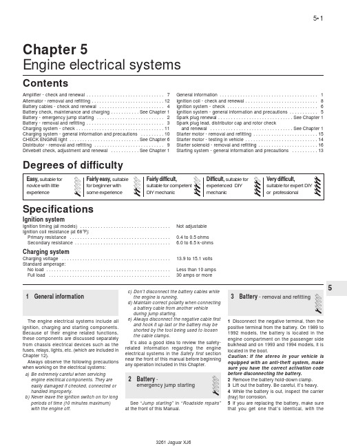
5Chapter 5Engine electrical systemsIgnition systemIgnition timing (all models) . . . . . . . . . . . . . . . . . . . . . . . . . . . . . . . . . . .Not adjustable Ignition coil resistance (at 68°F):Primary resistance . . . . . . . . . . . . . . . . . . . . . . . . . . . . . . . . . . . . . . .0.4 to 0.5 ohms Secondary resistance . . . . . . . . . . . . . . . . . . . . . . . . . . . . . . . . . . . . .6.0 to 6.5 k-ohms Charging systemCharging voltage . . . . . . . . . . . . . . . . . . . . . . . . . . . . . . . . . . . . . . . . . .13.9 to 15.1 volts Standard amperage:No load . . . . . . . . . . . . . . . . . . . . . . . . . . . . . . . . . . . . . . . . . . . . . . . .Less than 10 amps Full load . . . . . . . . . . . . . . . . . . . . . . . . . . . . . . . . . . . . . . . . . . . . . . .30 amps or moreAmplifier - check and renewal . . . . . . . . . . . . . . . . . . . . . . . . . . . . . .7Alternator - removal and refitting . . . . . . . . . . . . . . . . . . . . . . . . . . . .12Battery cables - check and renewal . . . . . . . . . . . . . . . . . . . . . . . . .4Battery check, maintenance and charging . . . . . . . . . . .See Chapter 1Battery - emergency jump starting . . . . . . . . . . . . . . . . . . . . . . . . . .2Battery - removal and refitting . . . . . . . . . . . . . . . . . . . . . . . . . . . . . .3Charging system - check . . . . . . . . . . . . . . . . . . . . . . . . . . . . . . . . . .11Charging system - general information and precautions . . . . . . . . .10CHECK ENGINE light . . . . . . . . . . . . . . . . . . . . . . . . . . .See Chapter 6Distributor - removal and refitting . . . . . . . . . . . . . . . . . . . . . . . . . . .9Drivebelt check, adjustment and renewal . . . . . . . . . . .See Chapter 1General information . . . . . . . . . . . . . . . . . . . . . . . . . . . . . . . . . . . . . .1Ignition coil - check and renewal . . . . . . . . . . . . . . . . . . . . . . . . . . . .8Ignition system - check . . . . . . . . . . . . . . . . . . . . . . . . . . . . . . . . . . .6Ignition system - general information and precautions . . . . . . . . . . .5Spark plug renewal . . . . . . . . . . . . . . . . . . . . . . . . . . . . .See Chapter 1Spark plug lead, distributor cap and rotor checkand renewal . . . . . . . . . . . . . . . . . . . . . . . . . . . . . . . .See Chapter 1Starter motor - removal and refitting . . . . . . . . . . . . . . . . . . . . . . . . .15Starter motor - testing in vehicle . . . . . . . . . . . . . . . . . . . . . . . . . . . .14Starter solenoid - removal and refitting . . . . . . . . . . . . . . . . . . . . . . .16Starting system - general information and precautions . . . . . . . . . .13SpecificationsContentsDegrees of difficulty1General informationThe engine electrical systems include all ignition, charging and starting components.Because of their engine related functions,these components are discussed separately from chassis electrical devices such as the fuses, relays, lights, etc. (which are included in Chapter 12).Always observe the following precautions when working on the electrical systems:a)Be extremely careful when servicing engine electrical components. They are easily damaged if checked, connected or handled improperly.b)Never leave the ignition switch on for long periods of time (10 minutes maximum)with the engine off.c)Don’t disconnect the battery cables while the engine is running.d)Maintain correct polarity when connecting a battery cable from another vehicle during jump starting.e)Always disconnect the negative cable first and hook it up last or the battery may be shorted by the tool being used to loosen the cable clamps.It’s also a good idea to review the safety-related information regarding the engine electrical systems in the Safety first section near the front of this manual before beginning any operation included in this Chapter.2Battery -emergency jump starting1See “Jump starting”in “Roadside repairs”at the front of this Manual.3Battery - removal and refitting11Disconnect the negative terminal, then the positive terminal from the battery. On 1989 to 1992 models, the battery is located in the engine compartment on the passenger side bulkhead and on 1993 and 1994 models, it is located in the boot.Caution: If the stereo in your vehicle is equipped with an anti-theft system, make sure you have the correct activation code before disconnecting the battery.2Remove the battery hold-down clamp.3Lift out the battery. Be careful, it’s heavy.4While the battery is out, inspect the carrier (tray) for corrosion.5If you are replacing the battery, make sure that you get one that’s identical, with thesame dimensions, amperage rating, cold cranking rating, etc. as the original.6Refitting is the reverse of removal.4Battery cables- check and renewal1 Caution: If the stereo in your vehicle is equipped with an anti-theft system, make sure you have the correct activation code before disconnecting the battery.1Periodically inspect the entire length of each battery cable for damage, cracked or burned insulation and corrosion. Poor battery cable connections can cause starting problems and decreased engine performance. 2Check the cable-to-terminal connections at the ends of the cables for cracks, loose wire strands and corrosion. The presence of white, fluffy deposits under the insulation at the cable terminal connection is a sign that the cable is corroded and should be renewed. Check the terminals for distortion, missing mounting bolts and corrosion.3When removing the cables, always disconnect the negative cable first and hook it up last or the battery may be shorted by the tool used to loosen the cable clamps. Even if only the positive cable is being renewed, be sure to disconnect the negative cable from the battery first (see Chapter 1 for further information regarding battery cable removal). 4Disconnect the cables from the battery, then trace each of them to their opposite ends and detach them from the starter solenoid and earth terminals. Note the routing of each cable to ensure correct refitting.5If you are replacing either or both of the old cables, take them with you when buying new items. It is vitally important that you replace the cables with identical parts. Cables have characteristics that make them easy to identify: positive cables are usually red, larger in cross-section and have a larger diameter battery post clamp; earth cables are usually black, smaller in cross-section and have a slightly smaller diameter clamp for the negative post.6Clean the threads of the solenoid or earth connection with a wire brush to remove rust and corrosion. Apply a light coat of battery terminal corrosion inhibitor, or petroleum jelly, to the threads to prevent future corrosion.7Attach the cable to the solenoid or earth connection and tighten the mounting nut/bolt securely.8Before connecting a new cable to the battery, make sure that it reaches the battery post without having to be stretched.9Connect the positive cable first, followed by the negative cable.5Ignition system- generalinformation and precautions1All models are equipped with a computerisedignition system. The ignition system consists ofthe ignition coil, the crankshaft position sensor,the amplifier and the electronic control unit(ECU). The ignition ECU controls the ignitiontiming and advance characteristics for theengine. The ignition timing is not adjustable,therefore, changing the position of the distributorwill not change the timing in any way. Note:Inthe event the distributor must be removed fromthe engine, be sure to follow the precautionsdescribed in Section 9 and mark the engine anddistributor with paint to ensure correct refitting. Ifthe distributor is not marked and Ihe crankshaft isturned while the distributor is out of the engine,have the distributor installed by a dealer servicedepartment. The distributor must be installedusing a special alignment tool.2The distributor is driven by the intermediateshaft which also drives the power steering pump.The crankshaft position sensor is located on thefront timing cover. It detects crank position bypulsing an electronic signal to the ECU. Thissignal is sent to the ECU to provide ignitiontiming specifications.3The computerised ignition system providescomplete control of the ignition timing bydetermining the optimum timing in response toengine speed, coolant temperature, throttleposition and vacuum pressure in the intakemanifold. These parameters are relayed to theECU by the crankshaft position sensor, throttlepotentiometer, coolant temperature sensor andMAF sensor. Ignition timing is altered duringwarm-up, idling and warm running conditions bythe ECU. This electronic ignition system alsoconsists of the ignition switch, battery, coil,distributor, spark plug leads and spark plugs.4Refer to a dealer parts department or caraccessory outlet for any questions concerningthe availability of the distributor parts andassemblies. Testing the crankshaft positionsensor is covered in Chapter 6.5When working on the ignition system, takethe following precautions:a)Do not keep the ignition switch on formore than 10 seconds if the engine willnot start.b)Always connect a tachometer inaccordance with the manufacturer’sinstructions. Some tachometers may beincompatible with this ignition system.Consult a dealer service departmentbefore buying a tachometer for use withthis vehicle.c)Never allow the ignition coil terminals totouch earth. Earthing the coil could resultin damage to the igniter and/or theignition coil.d)Do not disconnect the battery when theengine is running.6Ignition system- check2Warning: Because of the highvoltage generated by theignition system, extreme careshould be taken when workingon the ignition components. This not onlyincludes the amplifier, coil, distributor andspark plug leads, but related componentssuch as connectors, tachometer and othertest equipment also.1With the ignition switch turned to the “ON”position, a “Battery” light or an “Oil Pressure”light is a basic check for ignition and batterysupply to the ECU.2Check all ignition wiring connections fortightness, cuts, corrosion or any other signs of abad connection.3Use a calibrated ignition tester to verifyadequate secondary voltage (25,000 volts) ateach spark plug (see illustration). A faulty orpoor connection at that plug could also result in amisfire. Also, check for carbon deposits insidethe spark plug boot.4Check for carbon tracking on the coil. Ifcarbon tracking is evident, renew the coil and besure the secondary wires related to that coil areclean and tight. Excessive wire resistance orfaulty connections could damage the coil.5Check for battery voltage to the ignition coil(see illustration). If battery voltage is available,check the ignition coil primary and secondaryresistance (see Section 8).6Check the distributor cap for any obvioussigns of carbon tracking, corroded terminals orcracks (see Chapter 1).7Using an ohmmeter, check the resistance ofthe spark plug leads. Each wire should measureless than 25,000 ohms.8Check for battery voltage to the ignitionamplifier (see Section 7). If battery voltage doesnot exist, check the circuit from the ignitionswitch (refer to the wiring diagrams at the end ofChapter 12).5•2Engine electrical systems6.3 To use a calibrated ignition tester(available at most car accessory outlets),remove a plug lead from a cylinder,connect the spark plug boot to the testerand clip the tester to a good earth - if thereis enough voltage to fire the plug, sparkswill be clearly visible between theelectrode tip and the tester body9Check for battery voltage to the Ignition ON relay (see illustration). If battery voltage does not exist, check the circuit from the ignition ON relay to the battery (refer to the wiring diagrams at the end of Chapter 12). Note:See Chapter 12 for the location of the Ignition ON relay.10Check the operation of the crankshaft position sensor (see Chapter 6).11If all the checks are correct, check the voltage signal from the computer. Using an LED type test light, backprobe the coil power lead (negative terminal) on the ignition coil (see illustration). Remove the coil secondary wire and earth the terminal to the engine. Now have an assistant crank the engine over and observe that the test light pulses on and off. If there is no flashing from the test light, most likely the computer is damaged. Have the ECU diagnosed by a dealer service department.12Additional checks should be performed by a dealer service department or an automotive repair workshop.7Amplifier- check and renewal2Warning: Because of the highvoltage generated by theignition system, extreme careshould be taken whenever an operation is performed involving ignition components. This not only includes theamplifier, coil, distributor and spark plugleads, but related components such asconnectors, tachometer and other testequipment also.Note:Because of the complexity and thespecial tools required to test the amplifier, thefollowing procedure only describes a test toverify battery voltage is reaching the amplifier.If the wiring harness and the relays areworking properly and battery voltage isavailable to the amplifier, have the ignitionsystem and the ECU diagnosed by a dealerservice department.Check1Disconnect the amplifier electrical connector(see illustration).2Turn the ignition key ON (engine notrunning), check for battery voltage (seeillustration) to the amplifier.3If no battery voltage is present, check theharness from the ignition switch to theamplifier. Refer to the wiring diagrams at theend of Chapter 12.Renewal4Disconnect the negative battery terminal.Caution: If the stereo in your vehicle isequipped with an anti-theft system, makesure you have the correct activation codebefore disconnecting the battery.5Remove the amplifier mounting bolts (seeillustration).6Refitting is the reverse of removal.8Ignition coil-check and renewal2Check1Detach the cable from the negative terminalof the battery.Caution: If the stereo in your vehicle isequipped with an anti-theft system, makeEngine electrical systems 5•356.5 Check for battery voltage to thecoil (+) terminal 6.9 Check for battery voltageto the IGN ON relay6.11 Refit the LED test light to the coilnegative (-) terminal, crank the engine overand observe the light flash in response tothe trigger signal from the computer7.1 Remove the clip that retains theharness connector to the amplifier 7.2 Check for battery voltage to theignition amplifier7.5 Remove the amplifier mountingsscrews (arrowed) and lift the unit from theengine compartmentsure you have the correct activation code before disconnecting the battery.2Disconnect the electrical connectors and the coil wire from the coil.3Using an ohmmeter, check the coil resistance:a)Measure the resistance between thepositive and negative terminals (seeillustration). Compare your reading withthe specified coil primary resistance listed in this Chapter’s Specifications.b)Measure the resistance between thepositive terminal and the high tension (HT) terminal(see illustration). Compare yourreading with the specified coil secondaryresistance listed in this Chapter’sSpecifications.4If either of the above tests yield resistance values outside the specified amount, renew the coil.Renewal5Detach the battery negative cable. Caution: If the stereo in your vehicle is equipped with an anti-theft system, make sure you have the correct activation code before disconnecting the battery. 6Label and disconnect the electrical wiresfrom the coil terminals.7Remove the coil mounting fasteners (seeillustration).8Refitting is the reverse of removal.9Distributor-removal and refitting2Note:The timing on this ignition system cannotbe adjusted by turning the distributor. Ignitiontiming is maintained by the ECU at all times. Inthe event the distributor must be removed fromthe engine, be sure to follow the precautionsdescribed in this section and mark the engineand distributor with paint to ensure correctrefitting. If the distributor is not marked, and thecrankshaft is turned while the distributor is out ofthe engine, have the distributor installed by adealer service department. The distributor mustbe installed using a special alignment tool.Removal1Detach the battery negative cable.Caution: If the stereo in your vehicle isequipped with an anti-theft system, makesure you have the correct activation codebefore disconnecting the battery.2Disconnect the electrical connectors fromthe distributor.3Look for a raised “1” on the distributor cap.This marks the location for the number onecylinder spark plug lead terminal. If the capdoes not have a mark for the number oneterminal, locate the number one spark plugand trace the wire back to the terminal on thecap.4Remove the distributor cap (see Chapter 1)and rotate the engine until the rotor is pointingtoward the number one spark plug terminal.5Make a mark on the edge of the distributorbase directly below the rotor tip and in linewith it. Also, mark the distributor base and theengine block to ensure that the distributor isinstalled correctly (see illustrations).6Remove the distributor hold-down bolt,then pull the distributor out to remove it.Caution: DO NOT turn the crankshaft whilethe distributor is out of the engine, or thealignment marks will be useless.5•4Engine electrical systems8.3a To check the primary resistance of the coil, measure the resistance betweenthe positive and the negative terminals 8.3b To check the secondary resistance ofthe coil, measure the resistance betweenthe positive terminal and the HT terminal8.7 Remove the nuts from the coilmounting bracket (arrowed)9.5a Paint or scribe a mark (arrowed) on the edge of the distributor housing below the rotor tip to ensure that the rotor ispointing in the same direction when the distributor is reinstalled 9.5b Paint or scribe another mark across the cylinder head and the distributor body (arrowed) to ensure that the distributor isaligned correctly when it is reinstalledRefitting7Insert the distributor into the engine in exactly the same relationship to the block that it was in when removed.8If the distributor does not seat completely, recheck the alignment marks between the distributor base and the block to verify that the distributor is in the same position it was in before removal. Also check the rotor to see if it’s aligned with the mark you made on the edge of the distributor base.9Refit the distributor hold-down bolt(s).10The remainder of refitting is the reverse of removal.10Charging system- generalinformation and precautionsThe charging system includes the alternator, an internal voltage regulator, a charge indicator light, load dump module, the battery, an ignition ON relay, an in-line fuse and the wiring between all the components (see illustration). The charging system supplies electrical power for the ignition system, the lights, the radio, etc. The alternator is driven by a drivebelt at the front of the engine.The purpose of the voltage regulator is to limit the alternator’s voltage to a preset value. This prevents power surges, circuit overloads, etc., during peak voltage output.The alternator load dump module protects the electrical circuits from excessive voltage surges. When the battery cables are removed large amounts of transient voltage is released through the electrical circuits. This device diverts up to 30 load volts of excess voltage to earth by way of a voltage dependent resistor.The in-line fuse is a special fuse installed into the circuit with the engine compartment wiring harness (see Chapter 12). The in-line fuse protects the electrical system in the event of excess voltage surges or a power to earth short circuit. Refer to Chapter 12 for additional information concerning the in-line fuses and their locations.1993 and 1994 models have a Starter Logic Relay. This microprocessor (computer) gathers information from the ignition switch, linear gear position switch, park/neutral switch, the security switch and the electronic door lock system. If all the conditions are in order, the computer allows battery voltage to be transferred from the ignition switch to the starter/solenoid assembly.The charging system doesn’t ordinarily require periodic maintenance. However, the drivebelt, battery and wires and connections should be inspected at the intervals outlined in Chapter 1.The dashboard warning light should come on when the ignition key is turned to Start, then should go off immediately. If it remains on, there is a malfunction in the charging system. Some vehicles are also equipped with a voltage gauge. If the voltage gauge indicates abnormally high or low voltage,check the charging system (see Section 11).Be very careful when making electricalcircuit connections to a vehicle equipped withan alternator and note the following:a)When reconnecting wires to the alternatorfrom the battery, note their polarity.b)Before using arc welding equipment torepair any part of the vehicle, disconnectthe wires from the alternator and thebattery terminals.c)Never start the engine with a batterycharger connected.d)Always disconnect both battery leadsbefore using a battery charger.e)The alternator is driven by an enginedrivebelt which could cause serious injuryif your hand, hair or clothes becomeentangled in it with the engine running.f)Because the alternator is connecteddirectly to the battery, it could arc orcause a fire if overloaded or shorted out.g)Wrap a plastic bag over the alternator andsecure it with rubber bands before steamcleaning the engine.11Charging system- check2Note:1993 and 1994 models are equippedwith a Starter Logic Relay. This microprocessor(computer) gathers information from theignition switch, linear gear position switch,park/neutral switch, the security switch and theelectronic door lock system. If all the conditionsare in order, the computer allows batteryvoltage to be transferred from the ignitionswitch to the starter/solenoid assembly. If allthe components of the charging system areworking properly and the system still does notcharge properly, have the Starter Logic Relaydiagnosed by a dealer service department.1If a malfunction occurs in the chargingcircuit, don’t automatically assume that thealternator is causing the problem. First checkthe following items:a)Check the drivebelt tension and itscondition. Renew it if worn or damaged.b)Make sure the alternator mounting andadjustment bolts are tight.c)Inspect the alternator wiring harness andthe electrical connectors at the alternatorand voltage regulator. They must be ingood condition and tight.d)Check the fusible link (if equipped)located between the starter solenoid andthe alternator or the large main fuses inthe engine compartment. If it’s burned,determine the cause, repair the circuitand renew the link or fuse (the vehiclewon’t start and/or the accessories won’twork if the fusible link or fuse blows).e)Check all the in-line fuses that are in serieswith the charging system circuit (seeChapter 12).The location of these fusesand fusible links may vary from year andEngine electrical systems 5•5510.1 Schematic of a typical charging systemmodel but the designations are the same.Refer to the wiring diagrams at the end ofChapter 12.f)Start the engine and check the alternatorfor abnormal noises (a shrieking orsquealing sound indicates a bad bushing).g)Check the specific gravity of the batteryelectrolyte. If it’s low, charge the battery(doesn’t apply to maintenance freebatteries).h)Make sure that the battery is fully charged(one bad cell in a battery can causeovercharging by the alternator).i)Disconnect the battery cables (negativefirst, then positive). Caution:If the stereoin your vehicle is equipped with an anti-theft system, make sure you have thecorrect activation code beforedisconnecting the battery.Inspect thebattery posts and the cable clamps forcorrosion. Clean them thoroughly ifnecessary (see Chapter 1). Reconnect the positive cable, then the negative cable.2Using a voltmeter, check the battery voltage with the engine off. It should be approximately 12 volts (see illustration).3Start the engine and check the battery voltage again. It should now be approximately 13.5 to 15.1 volts.4Turn on the headlights. The voltage should drop and then come back up, if the charging system is working properly.5If the voltage reading is greater than the specified charging voltage, renew the alternator.6If you have an ammeter, connect it up to the charging system according to its maker’s instructions. If you don’t have a professional-type ammeter, you can also use an inductive-type current indicator. This device is inexpensive, readily available at car accessory outlets and accurate enough to perform simple amperage checks like the following test.7With the engine running at 2000 rpm, checkthe reading on the ammeter with allaccessories and lights off (no load), then againwith the high-beam headlights on and theheater blower switch turned to the HI position(full load). Compare your readings to thestandard amperage listed in this Chapter’sSpecifications.8If the ammeter reading is less than standardamperage, repair or renew the alternator.9If the alternator is working but the chargingsystem still does function properly, check theoperation of the load dump module (seeillustration). Have this component checked ata dealer service department.12Alternator-removal and refitting21Detach the cable from the negative terminalof the battery.Caution: If the stereo in your vehicle isequipped with an anti-theft system, makesure you have the correct activation codebefore disconnecting the battery.2Detach the electrical connectors from thealternator.3Loosen the alternator adjustment and pivotbolts (see illustration) and detach thedrivebelt.4Remove the adjustment and pivot bolts(see illustration)from the alternatoradjustment bracket.5If you are replacing the alternator, take theold alternator with you when purchasing areplacement unit. Make sure that thenew/rebuilt unit is identical to the oldalternator. Look at the terminals - they shouldbe the same in number, size and locations asthe terminals on the old alternator. Finally,look at the identification markings - they willbe stamped in the housing or printed on a tagor plaque affixed to the housing. Make surethat these numbers are the same on bothalternators.6Many new/rebuilt alternators do not havea pulley installed, so you may have to switchthe pulley from the old unit to the new/rebuiltone. When buying an alternator, find out thepolicy regarding refitting of pulleys - someshops will perform this service free of charge.7Refitting is the reverse of removal.5•6Engine electrical systems12.3 Loosen the lock bolt and back-off the adjustment bolt (arrowed) to removethe drivebelt12.4 Remove the pivot bolt and nut11.2 Connect the probes of a voltmeter to the battery terminalsand observe battery voltage with the engine OFFand then with the engine running 11.9 The load dump module is located on the bulkheadnext to the MAF sensor。
保时捷维修手册:997空调系
车间指南911Turbo(997)小组8空调使用保时捷车辆车间文件的前提条件这些数据包括:保时捷车辆的技术信息和修理说明,以及培训文件。
这些说明信息仅供车间和车间工作人员使用。
笔记♦Dr.Ing.h.c. F.Porsche AG保留对版权的独家所有权。
♦不得转交给第三方。
♦若无Dr.Ing.h.c. F.Porsche AG的明确同意,不得复制图片和文字或将它们用于其他电子或印刷出版物。
修理保时捷车辆的一般前提条件这些说明是正确地进行专业化保养与修理的基础。
所介绍的这些工作过程的内容要求装配工人对产品有全面的了解并接受过一定程度的培训。
装配工人在进行任何工作之前,必须已经通过Dr. Ing.h.c.F.Porsche AG专门为熟悉产品和装配而设立的培训计划和课程获得有关产品的知识。
掌握这种知识水平是执行所述工作的前提。
如果在未掌握这些知识的情况下进行所述的修理工作,Dr.Ing.h.c. F.Porsche AG概不负责。
保时捷车辆车身作业的前提条件所介绍的修理工作仅适用于标准情况。
只限专门从事车身修理的熟练人员进行此类工作。
车间应根据损坏的总体情况,自行判断是否可将车辆恢复成正常状况。
保时捷车辆的修理工作需要使用Dr.Ing.h.c. F.Porsche AG推荐和批准的工具和车间设备。
必须根据Dr.Ing.h.c. F.Porsche AG的钣金、喷漆和防蚀/防腐工作说明正确实施所有车身修理工作。
警告注释和安全指南警告注释和安全指南按警告符号旁边的相应提示文字(危险、警告、注意)分类。
危险如不遵守操作说明则必然导致死亡或重伤的警告。
警告如不遵守操作说明则可能会导致死亡或重伤的警告。
注意如不遵守操作说明则会导致轻伤或财产损失的警告。
为防止由于工作不当而导致伤害、损失车辆性能和交通安全性、或者损坏车辆,请仔细阅读这些警告注释和安全指南并严格遵守。
Dr.Ing.h.c. F.Porsche AG不可能为执行此项工作的人详细评估所有的危险状况。
2018年Porsche 911 GT3 GT2 RS维修指南说明书

Drain engine oil Change oil filter Underbody panels: visual inspection for completeness, secure installation and damage Tyres: check condition Visual inspection for leaks from underneath (oils and other fluids) Brake lines: visual inspection for damage, routing and corrosion Brake hoses: visual inspection for damage Steering gear: visual inspection of the bellows for damage Tie rod joints: check play and dust bellows Drive shafts: visual inspection of the boots for leaks and damage Axle joints: check the play and visually inspect the dust boots for damage Rear-axle steering: check bellows, dust boots and play on joints Anti-roll bar and connecting links: visual inspection for damage Check that threaded connections for chassis adjustment at front and rear are secure Check vehicle height Control boxes for exhaust flaps: check function Exhaust system: visual inspection for leaks and damage, check engine mount Replace spark plugs
捷豹维修手册
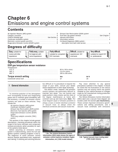
6Chapter 6Emissions and engine control systemsEGR gas temperature sensor resistanceTemperature:212°F . . . . . . . . . . . . . . . . . . . . . . . . . . . . . . . . . . . . . . . . . . . . . . . . .60 to 100 k-ohms 400°F . . . . . . . . . . . . . . . . . . . . . . . . . . . . . . . . . . . . . . . . . . . . . . . . . 3 to 8 k-ohms 662°F . . . . . . . . . . . . . . . . . . . . . . . . . . . . . . . . . . . . . . . . . . . . . . . . .250 to 350 ohms Torque wrench settingNm lbf ft Crankshaft sensor bolt . . . . . . . . . . . . . . . . . . . . . . . . . . . . . . . . . . . . . .2720Air Injection Reactor (AIR) system . . . . . . . . . . . . . . . . . . . . . . . . . . .5Catalytic converter . . . . . . . . . . . . . . . . . . . . . . . . . . . . . . . . . . . . . . .9CHECK ENGINE light . . . . . . . . . . . . . . . . . . . . . . . . . . .See Section 3Crankcase ventilation system . . . . . . . . . . . . . . . . . . . . . . . . . . . . . .8Electronic control system and ECU . . . . . . . . . . . . . . . . . . . . . . . . . .2Evaporative Emission Control (EVAP) system . . . . . . . . . . . . . . . . . .6Exhaust Gas Recirculation (EGR) system . . . . . . . . . . . . . . . . . . . . .6Fuel tank cap gasket renewal . . . . . . . . . . . . . . . . . . . . .See Chapter 1General information . . . . . . . . . . . . . . . . . . . . . . . . . . . . . . . . . . . . . .1Information sensors . . . . . . . . . . . . . . . . . . . . . . . . . . . . . . . . . . . . .4On Board Diagnosis (OBD) system -description and fault code access . . . . . . . . . . . . . . . . . . . . . . . . .3SpecificationsContentsDegrees of difficulty1General informationTo minimise pollution of the atmosphere from incompletely burned and evaporating gases and to maintain good driveability and fuel economy, a number of emission control systems are used on these vehicles. They include the:Air Injection Reactor (AIR) system Crankcase Ventilation systemExhaust Gas Recirculation (EGR) system Electronic Fuel Injection (EFI) system Evaporative Emission Control (EVAP)systemThree-way catalytic converter (TWC)systemThe sections in this chapter include general descriptions, checking procedures within the scope of the home mechanic and component renewal procedures (when possible) for each of the systems listed above.Before assuming an emissions control system is malfunctioning, check the fuel and ignition systems carefully (Chapters 4 and 5).The diagnosis of some emission control devices requires specialised tools, equipment and training. If checking and servicing becometoo difficult or if a procedure is beyond the scope of your skills, consult your dealer service department or other repair workshop.This doesn’t mean, however, that emission control systems are particularly difficult to maintain and repair. You can quickly and easily perform many checks and do most of the regular maintenance at home withcommon tune-up and hand tools. Note:The most frequent cause of emission problems is simply a loose or broken electrical connector or vacuum hose, so always check theelectrical connectors and vacuum hoses first.Pay close attention to any special precautions outlined in this chapter. It should be noted that the illustrations of the various systems may not exactly match the system installed on your vehicle because of changes made by the manufacturer during production or from year-to-year.The Vehicle Emissions Control Information (VECI) label and a vacuum hose diagram are located under the bonnet (see illustrations).These contain important emissions specifi-cations and setting procedures, and a vacuum hose schematic with emissions1.6a The Vehicle Emissions Control Information (VECI) label shows the types of emission control systems installed, engine information, etc (1992 model shown)1.6b Typical vacuum hose routing label(1992 model shown)components identified. When servicing the engine or emissions systems, the VECI label in your particular vehicle should always be checked for up-to-date information.2Electronic control systemand ECUGeneral descriptionNote: These models are susceptible to ECU damage if water is allowed to build up in the front cowl drain and overspill into the dash area near the computer. Inspect and clear the front cowl drain as a regular maintenance item to keep the water draining properly. Remove the duckbill-type rubber hose and inspect it for clogging, collapsing or deterioration.1The Lucas LH Engine Management system controls the fuel injection system by means of a microcomputer known as the Electronic Control unit (ECU).2The ECU receives signals from various sensors which monitor changing engine operating conditions such as intake air mass, intake air temperature, coolant temperature, engine rpm, acceleration/deceleration, exhaust oxygen content, etc. These signals are utilised by the ECU to determine the correct injection duration.3The system is analogous to the central nervous system in the human body: The sensors (nerve endings) constantly relay signals to the ECU (brain), which processes the data and, if necessary, sends out a command to change the operating parameters of the engine (body).4Here’s a specific example of how one portion of this system operates: An oxygen sensor, located in the exhaust manifold, constantly monitors the oxygen content of the exhaust gas. If the percentage of oxygen in the exhaust gas is incorrect, an electrical signal is sent to the ECU. The ECU takes this information, processes it and then sends a command to the fuel injection system telling it to change the air/fuel mixture. This happens in a fraction of a second and it goes on continuously when the engine is running. The end result is an air/fuel mixture ratio which is constantly maintained at a predetermined ratio, regardless of driving conditions.5In the event of a sensor malfunction, a backup circuit will take over to provide driveability until the problem is identified and fixed.Precautions6Follow these steps:a)Always disconnect the power by eitherturning off the ignition switch ordisconnecting the battery terminals before removing electrical connectors.Warning: Later models areequipped with airbags. Toprevent accidental deployment of the airbag, which could cause personalinjury, DO NOT work in the vicinity of thesteering column or instrument panel. Themanufacturer recommends that, on airbagequipped models, the following procedureshould be left to a dealer servicedepartment or other repair workshopbecause of the special tools and techniquesrequired to disable the airbag system.Caution: If the stereo in your vehicle isequipped with an anti-theft system, makesure you have the correct activation codebefore disconnecting the battery.b)When refitting a battery, be particularlycareful to avoid reversing the positive andnegative battery cables. Also, make surethe ignition key is in the Off position whenconnecting or disconnecting the battery.c)Do not subject EFI components,emissions-related components or theECU to severe impact during removal orrefitting.d)Do not be careless during fault diagnosis.Even slight terminal contact can invalidatea testing procedure and damage one ofthe numerous transistor circuits.e)Never attempt to work on the ECU oropen the ECU cover. The ECU isprotected by a government-mandatedextended warranty that will be nullified ifyou tamper with or damage the ECU.f)If you are inspecting electronic controlsystem components during rainy weather,make sure that water does not enter anypart. When washing the enginecompartment, do not spray these parts ortheir electrical connectors with water.g)These models are susceptible to ECUdamage if water is allowed to build up inthe front cowl drain and overspill into thedash area. Inspect and clear the frontcowl drain system as a regularmaintenance item to keep the waterdraining properly. Remove the duckbilltype rubber hose and inspect it forclogging, collapsing or deterioration.ECU removal and refitting7Disconnect the negative cable from thebattery (see Chapter 5).Warning: Later models areequipped with airbags. Toprevent the accidental deploy-ment of the airbag, which couldcause personal injury, DO NOT work in thevicinity of the steering column orinstrument panel. The manufacturerrecommends that, on airbag equippedmodels, the following procedure should beleft to a dealer service department or otherrepair workshop because of the specialtools and techniques required to disablethe airbag system.Caution: If the stereo in your vehicle isequipped with an anti-theft system, makesure you have the correct activation codebefore disconnecting the battery.8Remove the lower instrument panel on thepassenger side under the glove compartment(see Chapter 11).9Remove the glove compartment from thepassenger compartment (see Chapter 11).10Remove the screws from the ECU bracket(see illustration).11Lower the ECU and unplug the electricalconnectors.12Refitting is the reverse of removal.3On Board Diagnosis (OBD)system- description and faultcode access2Note: 1990 and 1991 models may setCode 69 erroneously. If the battery voltagedrops sufficiently and the ignition key isswitched quickly from OFF to START, batteryvoltage will be lowered and during crankingcausing a delayed park/neutral signal from thedecoder module to the ECU. Check all thebattery connections and the condition of thebattery and then check the rotary switchadjustment in Chapter 7 to remedy this code.General information1The ECU contains a built-in self-diagnosissystem which detects and identifiesmalfunctions occurring in the network. Whenthe ECU detects a problem, three thingshappen: the CHECK ENGINE light comes on,the fault is identified and a diagnostic code isrecorded and stored. The ECU stores thefailure code assigned to the specific problemarea until the diagnosis system is cancelled.Note: 1988 and 1989 models are notequipped with long term memory. It ispossible to access the codes but the operatormust remember to NOT turn the ignition key tothe OFF position after the CHECK ENGINElight has been noticed. The codes will be lostand it will be necessary to start the engine andoperate the vehicle through a complete drivecycle to allow the fault code(s) to be set onceagain. Instead of turning the ignition key to theOFF position, simply stop at position II (keyON but engine not running) to retain the faultcodes.6•2Emissions and engine control systems2.10 The ECU is located behind thepassenger’s side glovebox near the footrestarea. Remove the mounting screws(arrowed) and carefully lower the ECU2The CHECK ENGINE warning light, which is located on the instrument panel, comes on when the ignition switch is turned to ON and the engine is not running. When the engine is started, the warning light should go out. If the light remains on, the self-diagnosis system has detected a malfunction. Note: The CHECK ENGINE light on early models is displayed on the dashboard VCM panel on the right side. Later models are equipped with a separate CHECK ENGINE light on the left side of the instrument cluster.Note:Not all the codes will cause the CHECK ENGINE light to activate. When performing any fuel or emissions systems diagnosis, always check for codes that may be stored but not indicated by the CHECK ENGINE light.Obtaining fault code output3To obtain an output of diagnostic codes, verify first that the battery voltage is above 11 volts, the throttle is fully closed, the transmission is in Park, the accessory switches are off and the engine is at normal operating temperature.4Turn the ignition switch to ON but don’t start the engine (Position II). Note:On 1988 and 1989 models, remember to turn the ignition switch to position II without turning the key to OFF.5Press the VCM button on the display panel (see illustration)and observe the LED display on the dash for the designated codes. An asterisk next to the code indicates that there are multiple codes stored.6The numerical values will be displayed on the trip computer display on the dashboard. 7If there are any malfunctions in the system, the corresponding fault codes are displayed in numerical order, lowest to highest. Cancelling a diagnostic code8After the faulty component has been repaired/renewed, the fault code(s) stored in computer memory must be cancelled.a) On 1988 to 1991 vehicles, simply drivethe vehicle faster than 19 mph and the computer will automatically erase the stored fault code from memory.b) On 1992 to 1994 models, disconnect thenegative battery lead for 30 seconds ormore to erase the stored fault codes.Caution: If the stereo in your vehicle isequipped with an anti-theft system, makesure you have the correct activation codebefore disconnecting the battery.9A stored code can also be cancelled onearly models by removing the cable from thebattery negative terminal, but other items withmemory (such as the clock and radio presets)will also be cancelled.10If the diagnosis code is not cancelled, itwill be stored by the ECU and appear with anynew codes in the event of future trouble.11Should it become necessary to work onengine components requiring removal of thebattery terminal, always check to see if adiagnostic code has been recorded beforedisconnecting the battery.4Information sensorsNote: Refer to Chapters 4 and 5 for additionalinformation on the location and the diagnosticprocedures for the output actuators (ISCmotor, air supplementary valve, distributor,amplifier, etc.) that are not directly covered inthis section.Coolant temperature sensorGeneral description1The coolant temperature sensor is athermistor (a resistor which varies the value ofits voltage output in accordance withtemperature changes) which is threaded intothe thermostat housing. As the sensortemperature DECREASES, the resistancevalues will INCREASE. As the sensorEmissions and engine control systems 6•363.5 To access the self-diagnosis system fault codes, locate the VCM button on the dash and with the ignition key ON (enginenot running) press it to display the codes Fault code chart for 1988 and 1989 modelsCode System affected Probable cause1Oxygen sensor Open oxygen sensor circuit2Airflow sensor Not in operating range3Coolant temperature sensor Not in operating range4Oxygen sensor System indicates full rich5Throttle potentiometer/airflow sensor Low throttle potentiometer signalwith high airflow sensor signal6Throttle potentiometer/airflow sensor High throttle potentiometer signalwith low airflow sensor signal7Throttle potentiometer Idle fuel adjustment failure8Intake air temperature sensor Open or shorted circuit in IAT sensorharnessFault code chart for 1990 to 1994 modelsCode System affected Probable cause11Idle potentiometer Not in operating range12Airflow sensor Not in operating range14Coolant temperature sensor Not in operating range16Air temperature sensor Not in operating range17Throttle potentiometer Not in operating range18Throttle potentiometer/airflow sensor Signal resistance lowat wide open throttle19Throttle potentiometer/airflow sensor Signal resistance high at idle22Heated oxygen sensor Open or short circuit22Fuel pump circuit Open or short circuit23Fuel supply Rich exhaust Indicated24Ignition amplifier circuit Open or short circuit26Oxygen sensor circuit Lean exhaust/vacuum leak29ECU Self check33Fuel injector circuit Open or short circuit34Fuel injector circuit Faulty injector indicated37EGR solenoid circuit Short or open circuit39EGR circuit Faulty system operation44Oxygen sensor circuit Rich or lean condition46Idle speed control valve - (coil 1)Open or short circuit47Idle speed control valve - (coil 2)Open or short circuit48Idle speed control valve Not within specification68Road speed sensor Incorrect signal voltage69Neutral safety switch circuit Engine cranks in Drive(adjust or renew switch)89Purge control valve circuit Open or short circuittemperature INCREASES, the resistance values will DECREASE. A failure in this sensor circuit should set a Code 3 (1988 and 1989) or 13 (1990 to 1994). This code indicates a failure in the coolant temperature sensor circuit, so in most cases the appropriate solution to the problem will be either repair of a connector or wire, or renewal of the sensor.Check2To check the sensor, measure its resistance value (see illustration)while it is completely cold (60 to 80°F = 1500 to 3000 ohms). Next,start the engine and warm it up until it reaches operating temperature. The resistance should be lower (180 to 200°F = 280 to 350 ohms).3If the resistance values of the coolant temperature sensor are correct, check the circuit for the proper signal voltage. Turn the ignition key ON (engine not running) and check for reference voltage with a high-impedance digital voltmeter (see illustration).It should be approximately 5 volts.RenewalWarning: Wait until the engine is completely cool before beginning this procedure.4To remove the sensor, depress the locking tabs, unplug the electrical connector, then carefully unscrew the sensor.Caution: Handle the coolant sensor with care. Damage to this sensor will affect the operation of the entire fuel injection system.5Before refitting the new sensor, wrap the threads with Teflon sealing tape to prevent leakage and thread corrosion.6Refitting is the reverse of removal.Oxygen sensorNote:An oxygen sensor splash shield is equipped on models from VIN 664941 (mid-1990) to present. This shield prevents the self diagnosis system from setting an intermittent and erroneous code 44. Whenever replacing an oxygen sensor, make sure the splash shield is in place.General description7These models are equipped with a heatedoxygen sensor system. The oxygen sensor ismounted ahead of the front catalytic converterand monitors the exhaust gases before theyare changed. The electrical heating systemincorporated into the oxygen sensor allows forquicker warm-up time and more efficientoxygen content monitoring. The oxygen sensormonitors the oxygen content of the exhaustgas stream. The oxygen content in the exhaustreacts with the oxygen sensor to produce avoltage output which varies from 0.1 volts (highoxygen, lean mixture) to 0.9 volts (low oxygen,rich mixture). The ECU constantly monitors thisvariable voltage output to determine the ratio ofoxygen to fuel in the mixture. The ECU altersthe air/fuel mixture ratio by controlling the pulsewidth (open time) of the fuel injectors. A mixtureratio of 14.7 parts air to 1 part fuel is the idealmixture ratio for minimising exhaust emissions,thus allowing the catalytic converter to operateat maximum efficiency. This ratio of 14.7 to 1 is the one which the ECU and the oxygen sensor attempt to maintain at all times.8The oxygen sensor produces no voltagewhen it is below its normal operatingtemperature of about 600°F. During this initialperiod before warm-up, the ECU operates inopen loop mode.9If the engine reaches normal operatingtemperature and/or has been running for two ormore minutes, and if the oxygen sensor isproducing a steady signal voltage below0.45 volts at 1500 or more rpm, the ECU will seta Code 4 (1988 and 1989) or 26 (1990 to 1994).10When there is a problem with the oxygensensor or its circuit, the ECU operates in theopen loop mode - that is, it controls fuel delivery in accordance with a programmed default value instead of feedback information from the oxygen sensor.11The proper operation of the oxygen sensor depends on four conditions:a)Electrical - The low voltages generated bythe sensor depend upon good, cleanconnections which should be checked whenever a malfunction of the sensor is suspected or indicated.b)Outside air supply - The sensor is designed to allow air circulation to the internal portion of the sensor. Whenever the sensor is removed and installed or renewed, make sure the air passages are not restricted.c)Proper operating temperature - The ECU will not react to the sensor signal until the sensor reaches approximately 600°F.This factor must be taken into consideration when evaluating the performance of the sensor.d)Unleaded fuel - The use of unleaded fuel is essential for proper operation of the sensor. Make sure the fuel you are using is of this type.12In addition to observing the above conditions, special care must be takenwhenever the sensor is serviced.a)The oxygen sensor has a permanently attached pigtail and electrical connector which should not be removed from the sensor. Damage to or removal of the pigtail or electrical connector can adversely affect operation of the sensor.b)Grease, dirt and other contaminants should be kept away from the electrical connector and the louvered end of the sensor.c)Do not use cleaning solvents of any kind on the oxygen sensor.d)Do not drop or roughly handle the sensor.6•4Emissions and engine control systems4.2 The coolant temperature sensor is in the thermostat housing.To check the coolant temperature sensor, use an ohmmeter to measure the resistance between the two sensor terminals 4.3 Check for reference voltage to the electrical connector for the coolant sensor with the ignition key ON (engine not running).It should be approximately 5.0 voltse)The silicone boot must be installed in thecorrect position to prevent the boot frombeing melted and to allow the sensor tooperate properly.Check13Locate the oxygen sensor electrical connector and inspect the oxygen sensor heater. Disconnect the oxygen sensor electrical connector and connect an ohmmeter between the two terminals (see illustration). It should be around 5 to 6 ohms. 14Also, check for proper supply voltage to the oxygen sensor heater. Measure the voltage with the electrical connector connected. Insert a long pin into the backside of the electrical connector on the correct wire. With the ignition key ON (engine not running), check for voltage. There should be approximately 12 volts. Note:Battery voltage to the heater is supplied by the main relay (1988 to 1990) or the oxygen sensor relay (1991 to 1994). Check the oxygen sensor relay and the wiring harness if battery voltage is not available to the heater. Refer to the wiring diagrams at the end of Chapter 12 and the relay locator schematics also in Chapter 12.15Next, check for a millivolt signal from the oxygen sensor. Locate the oxygen sensor electrical connector and insert a long pin into the oxygen sensor signal wire terminal (see illustration). The SIGNAL wire is the single wire with the rubber sheath covering its terminal.16Monitor the voltage signal (millivolts) as the engine goes from cold to warm.17The oxygen sensor will produce a steady voltage signal at first (open loop) of approximately 0.1 to 0.2 volts with the engine cold. After a period of approximately two minutes, the engine will reach operating temperature and the oxygen sensor will start to fluctuate between 0.1 to 0.9 volts (closedloop). If the oxygen sensor fails to reach theclosed loop mode or there is a very longperiod of time until it does switch into closedloop mode, or if the voltage doesn’t fluctuatewell (indicating a “lazy” sensor), renew theoxygen sensor with a new part.RenewalNote:Because it is installed in the exhaustmanifold or pipe, which contracts when cool,the oxygen sensor may be very difficult toloosen when the engine is cold. Rather thanrisk damage to the sensor (assuming you areplanning to reuse it in another manifold orpipe), start and run the engine for a minute ortwo, then shut it off. Be careful not to burnyourself during the following procedure.18Disconnect the cable from the negativeterminal of the battery.Caution: If the stereo in your vehicle isequipped with an anti-theft system, makesure you have the correct activation codebefore disconnecting the battery.19Raise the vehicle and place it securely onaxle stands.20Disconnect the electrical connectors fromthe sensor pigtail lead.21Unscrew the oxygen sensor from theexhaust system (see illustration).Caution: Excessive force may damage thethreads.22Anti-seize compound must be used onthe threads of the sensor to facilitate futureremoval. The threads of new sensors willalready be coated with this compound, but ifan old sensor is removed and reinstalled,recoat the threads.23Refit the sensor and tighten it securely.24Reconnect the electrical connectors tothe main engine wiring harness.25Lower the vehicle and reconnect the cableto the negative terminal of the battery.Throttle potentiometerGeneral description26The throttle potentiometer is located onthe end of the throttle shaft on the bottomsection of the throttle body. By monitoring theoutput voltage from the throttlepotentiometer, the ECU can alter fuel deliverybased on throttle valve angle (driver demand).A broken or loose throttle potentiometer willcause bursts of fuel from the injectors and anunstable idle because the ECU thinks thethrottle is moving. Throttle body removalprocedures are covered in Chapter 4.Check27Check for the proper reference voltage tothe throttle potentiometer. Carefully back-probe the throttle potentiometer electricalconnector using a pin on the reference voltagewire and ground (see illustration). With theignition key ON (engine not running) thereference voltage should be about 5.0 volts.Emissions and engine control systems 6•564.21 Unscrew the oxygen sensor from theexhaust system4.13 To test the oxygen sensor heater, disconnect the electrical connector, and working on the sensor side, check the resistanceacross the two terminals. Heater resistance should be 5 to 6 ohms 4.15 Refit a pin into the backside of the oxygen sensor connector into the correct terminal and check for a millivolt output signal generated by the sensor as it warms up. The SIGNAL wire is easilyrecognised by the rubber sheath covering the terminal (arrowed)28Check the signal voltage from the potentiometer. Carefully backprobe the electrical connector on the signal voltage wire (-) with the ignition key ON (engine not running) (see illustration). There should be approximately 0.5 volts.29Next, rotate the throttle lever manually and confirm that the reference voltage increases to approximately 4.8 volts (see illustration).30If the voltage does not increase, renew the throttle potentiometer with a new part. Renewal31Remove the throttle body from the intake manifold (see Chapter 4).32Remove the two mounting bolts and separate the throttle potentiometer from the throttle body. Note:The throttle potentiometer is difficult to reach and adjustment requires that the home mechanic tighten the bolts after the final adjustment using a mirror. Be sure to mark the mounting position of the old throttle potentiometer before refitting the new part.33Refitting is the reverse of removal. Adjustment34Refit the throttle body with the throttle potentiometer mounting bolts just loose enough to move the potentiometer. Be surethe bolts are tight and the potentiometer doesnot rotate easily.35Backprobe the signal wire and the groundwire (see Step 28) and with the throttle closed(idle position), rotate the potentiometer untilthe voltmeter reads between 0.2 and 0.5 volts.Note:The throttle potentiometer is difficult toreach. Be sure to rotate the potentiometerslowly and do not interfere with the voltmeterand the electrical connectors to the gauge.36Rotate the throttle lever and confirm thatthe voltage increases to around 4.8 volts.If the voltage range is correct, the throttlepotentiometer is installed correctly.37Tighten the throttle potentiometer bolts. Ifnecessary, use a small mirror to locate thebolts.Mass airflow (MAF) sensorGeneral Information38The mass airflow sensor (MAF) is locatedon the air intake duct. This sensor uses a hotwire sensing element to measure the amountof air entering the engine. The air passing overthe hot wire causes it to cool. Consequently,this change in temperature can be convertedinto an analogue voltage signal to the ECUwhich in turn calculates the required fuelinjector pulse width.Check39Check for power to the MAF sensor.Backprobe the MAF sensor electrical plug.Working on the harness side with the ignitionON (engine not running), check for batteryvoltage on terminal number 5 (see illustration).40Remove the pin and backprobe the MAFsensor electrical connector terminal number 3with the voltmeter (see illustration). Thevoltage should be less than 1.0 volt with theignition switch ON (engine not running). Raisethe engine rpm. The signal voltage from theMAF sensor should increase to about 2.0 volts.It is impossible to simulate load conditions inthe driveway but it is necessary to observe thevoltmeter for a fluctuation in voltage as theengine speed is raised. The vehicle will not beunder load conditions but MAF sensor voltageshould vary slightly.41If the voltage readings are correct, checkthe wiring harness for open circuits or adamaged harness (see Chapter 12).6•6Emissions and engine control systems4.29 . . . then check the SIGNAL voltage with the throttle wide open. It should bebetween 4.5 and 5.0 volts 4.39 Check for battery voltage to the MAFsensor on terminal number 54.40 With the engine idling, raise the enginerpm and observe the voltage changes onterminal number 34.27 Backprobe the throttle potentiometer electrical connector with a pin and with the ignition key ON (engine not running) thereshould be 5.0 volts REFERENCE available 4.28 First check the throttle potentiometer SIGNAL voltage with thethrottle closed (idle). It should be 0.2 to 0.5 volts . . .。
2011款保时捷卡宴电器系统车间维修手册(下册)(可编辑)
2011款保时捷卡宴电器系统车间维修手册(下册)97 电缆 Cayenne 9PA电缆9700IN 测量闭路电流工具名称类型编号说明P 9718PIWIS 检测仪专用工具工具必须用 PIWIS 检测仪 P 9718模拟式电流表或带长集成时间的数字式万用表(用于滤除电压峰值)来测量闭路电流。
数字式万用表在车辆上进行的准备工作笔记在测量闭路电流之前,请先确定车辆设备(I-编号),并借助附表的帮助来确定预期的闭路电流。
闭路电流的测量只能在冷车(发动机&制动器)上进行。
1. 关闭车辆上的所有车门及盖。
测量闭路电流页 530打印在德国,11/0697 电缆 Cayenne 9PA2. 读取故障记忆,必要时删除所显示的故障。
3. 断开蓄电池。
连接测量设备1. 使用鳄鱼夹将测量设备连接至蓄电池接地设备及车身接地设备。
2. 拔掉车身的接地端,并与车身牢牢接触。
现在,车辆的所有电流都会流过电流表。
测量请选择一个测量范围,确保仪表指针在刻度较大值一端的三分之一处(越大越好)。
在不中断的情况下切换测量范围。
在表中指定的等待时间段后,读取测量值。
1. 打开点火开关 10 秒钟。
2. 关闭点火开关。
3. 打开驾驶员侧车门并在车门开启时用螺丝刀封闭旋转锁销。
4. 用中控锁遥控器锁住车辆,关闭乘客席监控(在 1 秒内按遥控器按钮两次)。
5. 读取闭路电流。
笔记如果闭路电流值高于表中规定的值,则要系统地分析其原因。
推荐的故障诊断程序: 采用所连接的测量装置,先后拆下端子30的保险丝以及继电器。
注意拆卸保险丝和继电器时测量装置上显示的值,以检测电流的减小。
可能的测量值变化范围大约是 20%。
表中列出的值取决于蓄电池状况、室温和发动机温度。
读取测量范围:车辆锁定至少 20 分钟后,才读取测量范围。
mA从到20 分钟。
直到蓄电池没电最多 35测量闭路电流页 531打印在德国,11/0697 电缆 Cayenne 9PA控制单元设备闭合电路电流 mA0.3DME(电机)标准0.424分动箱(纵向锁)标准0.424横向锁0.5自动变速器标准ESP 0.5标准0.425空气悬架0.5驾驶员座椅(带记忆)0.5乘客座椅(带记忆)0.2空调标准0.5辅助加热器0.5倒车辅助1.9Kessy控制单元(带无线电遥控, 无防盗系统/遥控模块)2.8Kessy控制单元(带无线电遥控, 无防盗系统/“Keyless Go”(无钥匙启动))0.3安全气囊标准1车辆电气系统标准0.1拖车 Westfalia0.5风挡刮水器标准0.5轮胎压力控制0.55电气可调节转向柱3组合仪表标准0.25驾驶员侧前门(无驾驶员侧 & 乘标准客侧车门 LED)0.25乘客侧前门标准0.25左后门标准0.25右后门标准1.4带(不带)蓄电池喇叭的后部控制单元0.5全景式天窗0.5收音机 CDR232.4PCM(CDR 23 的更高速档)0.11导航(PCM 的更高速档)测量闭路电流页 532打印在德国,11/0697 电缆 Cayenne 9PA 0.95CD 换碟机0.03天线放大器0.2电话/车载信息系统0.5后部娱乐设备0.3放大器3.6乘客席监控倾斜传感器0.05选档杆模块1.62蓄电池喇叭1拖车防盗控制6. 接上蓄电池并读出故障记忆。
保时捷维修手册:987_TI_7c

技术信息Boxster(987)小组7车身—内侧设备©Dr.Ing.h.c.F.Porsche AG使用保时捷车辆车间文件的前提条件这些数据包括:保时捷车辆的技术信息和修理说明,以及培训文件。
这些说明信息仅供车间和车间工作人员使用。
笔记•Dr.Ing.h.c.F.Porsche AG保留对版权的独家所有权。
•不得转交给第三方。
•若无Dr.Ing.h.c.F.Porsche AG的明确同意,不得复制图片和文字或将它们用于其他电子或印刷出版物。
修理保时捷车辆的一般前提条件这些说明是正确地进行专业化保养与修理的基础。
所介绍的这些工作过程的内容要求装配工人对产品有全面的了解并接受过一定程度的培训。
装配工人在进行任何工作之前,必须已经通过Dr.Ing.h.c.F.Porsche AG 专门为熟悉产品和装配而设立的培训计划和课程获得有关产品的知识。
掌握这种知识水平是执行所述工作的前提。
如果在未掌握这些知识的情况下进行所述的修理工作,Dr.Ing.h.c.F.Porsche AG概不负责。
保时捷车辆车身作业的前提条件所介绍的修理工作仅适用于标准情况。
只限专门从事车身修理的熟练人员进行此类工作。
车间应根据损坏的总体情况,自行判断是否可将车辆恢复成正常状况。
保时捷车辆的修理工作需要使用Dr.Ing.h.c. F.Porsche AG推荐和批准的工具和车间设备。
必须根据Dr.Ing.h.c.F.Porsche AG的钣金、喷漆和防蚀/防腐工作说明正确实施所有车身修理工作。
警告注释和安全指南警告注释和安全指南按警告符号旁边的相应提示文字(危险、警告、注意)分类。
危险如不遵守操作说明则必然导致死亡或重伤的警告。
警告如不遵守操作说明则可能会导致死亡或重伤的警告。
注意如不遵守操作说明则会导致轻伤或财产损失的警告。
为防止由于工作不当而导致伤害、损失车辆性能和交通安全性、或者损坏车辆,请仔细阅读这些警告注释和安全指南并严格遵守。
- 1、下载文档前请自行甄别文档内容的完整性,平台不提供额外的编辑、内容补充、找答案等附加服务。
- 2、"仅部分预览"的文档,不可在线预览部分如存在完整性等问题,可反馈申请退款(可完整预览的文档不适用该条件!)。
- 3、如文档侵犯您的权益,请联系客服反馈,我们会尽快为您处理(人工客服工作时间:9:00-18:30)。
技术信息
911(996)
小组3
动力传输©Dr.Ing.h.c.F.Porsche AG
使用保时捷车辆车间文件的前提条件
这些数据包括:保时捷车辆的技术信息和修理说明,以及培训文件。
这些说明信息仅供车间和车间工作
人员使用。
笔记
•Dr.Ing.h.c.F.Porsche AG保留对版权的独家所有权。
•不得转交给第三方。
•若无Dr.Ing.h.c.F.Porsche AG的明确同意,不得复制图片和文字或将它们用于其他电子或印刷出版物。
修理保时捷车辆的一般前提条件
这些说明是正确地进行专业化保养与修理的基础。
所介绍的这些工作过程的内容要求装配工人对产品有全面的了解并接受过一定程度的培训。
装配工人在进行任何工作之前,必须已经通过Dr.Ing.h.c.F.Porsche AG 专门为熟悉产品和装配而设立的培训计划和课程获得有关产品的知识。
掌握这种知识水平是执行所述工作的前提。
如果在未掌握这些知识的情况下进行所述的修理工作,Dr.Ing.h.c.F.Porsche AG概不负责。
保时捷车辆车身作业的前提条件
所介绍的修理工作仅适用于标准情况。
只限专门从事车身修理的熟练人员进行此类工作。
车间应根据损
坏的总体情况,自行判断是否可将车辆恢复成正常状况。
保时捷车辆的修理工作需要使用Dr.Ing.h.c. F.Porsche AG推荐和批准的工具和车间设备。
必须根据Dr.Ing.h.c.F.Porsche AG的钣金、喷漆和防
蚀/防腐工作说明正确实施所有车身修理工作。
警告注释和安全指南
警告注释和安全指南按警告符号旁边的相应提示文字(危险、警告、注意)分类。
危险
如不遵守操作说明则必然导致死亡或重伤的警告。
警告
如不遵守操作说明则可能会导致死亡或重伤的警告。
注意
如不遵守操作说明则会导致轻伤或财产损失的警告。
为防止由于工作不当而导致伤害、损失车辆性能和交通安全性、或者损坏车辆,请仔细阅读这些警告注
释和安全指南并严格遵守。
Dr.Ing.h.c.F.Porsche AG不可能为执行此项工作的人详细评估所有的危险状况。
因此,所有对保时捷车辆进行修理和维护的人都必须依靠自己的专门知识来保证自己的安全,并且所选择的过程不会对车辆带来
任何负面效果,尤其不能损失车辆的安全性能。
因此,说明中明确指出,所述的工作过程中涉及的所有工作都必须遵守当地管理机构有关健康、事故预防和环境保护的有效指南和规则,并要符合适用的法律要求和法规规定。
注释
注释中针对如何使装配工人更便于工作提供了建议的工作过程。
下面的图示指明了这些信息:
页1of4©Dr.Ing.h.c.F.Porsche AG
Printed in Germany
笔记
•包含可以简化工作过程的建议信息。
由于我们的车辆在不断地发展与改进,因此车辆的实际技术状态和工作描述之间可能存在差异。
任何现
有的偏差都用补遗的方式加以修正,并用补遗来扩展描述的范围。
Dr.Ing.h.c.F.Porsche AG保留随时实施变化的权利,恕不另行通知。
©Dr.Ing.h.c.F.Porsche AG
Printed in Germany页2of4
911(996)目录
3动力传输
3435批准手动变速器修理工作..................................1/064
页3of4©Dr.Ing.h.c.F.Porsche AG
Printed in Germany
技术信息911(996)
1/06ZH34353
批准手动变速器修理工作
车辆类型:911Carrera(996)/911Carrera4(996)
式样年:1998始于2005到
设备:配备手动变速器的车辆(G96.00/G96.30/G96.01/G96.31)
关注事项:手动变速器:批准修理工作。
情况:在手动变速器上进行装配操作。
对于911Carrera(996)和911Carrera4(996)上的手动变速器而言,自即日起批准所有维
修工作。
各步骤详见《车间手册》中的说明。
所要求的配件有库存。
笔记
•要求使用专用工具对手动变速器进行维修。
《车间手册》列出了这些工具。
•如果为进行维修而不得不将齿轮压出,请使用《车间设备手册》中指定的推荐使用的车
间压力机,因为此操作所涉压力可能高达30t(300kN)。
参考资料:⇒《车间手册》,“3—变速器,手动变速器”。
⇒《车间设备手册》,“3.0.2.节—车间设备–>维修–>车间压力机”。
©Dr.Ing.h.c.F.Porsche AG Printed in Germany 2006-9-28页4of4。
