【JPD1653900S】外观设计【专利】
bp1658cj规格书

bp1658cj规格书BP1658CJ规格书介绍•BP1658CJ规格书是一份详细的产品规格书,旨在提供有关BP1658CJ的各项技术指标和性能参数的信息。
主要特点•高精度测量:BP1658CJ采用先进的测量技术,能够实现高精度的测量结果。
•多功能设计:BP1658CJ具备多项功能,包括计算、数据存储和分析等,可满足不同需求。
•直观操作界面:BP1658CJ设计了直观易用的操作界面,使用户能够轻松上手,快速上手。
•多种接口方式:BP1658CJ支持多种接口方式,如USB、RS232和WiFi等,便于与其他设备进行连接和数据传输。
技术指标•测量精度:±•测量范围:0-500mm•响应时间:≤•工作温度:-10℃~50℃•电源:DC 12V•尺寸:150mm×80mm×30mm•重量:200g应用领域•制造业:BP1658CJ可广泛应用于制造业的尺寸测量、质量控制等方面,提高生产效率和产品质量。
•科研机构:BP1658CJ可在科研机构中用于各种尺寸测量和实验数据采集等领域。
•教育培训:BP1658CJ也可作为教育培训的辅助工具,用于教学实验和学术研究。
总结•BP1658CJ是一款高精度、多功能的测量仪器,具备直观易用的操作界面和多种接口方式。
它在制造业、科研机构和教育培训等领域都有着广泛的应用前景。
详细的技术指标和性能参数可参考BP1658CJ规格书。
BP1658CJ规格书介绍•BP1658CJ规格书是一份详细的产品规格书,旨在提供有关BP1658CJ的各项技术指标和性能参数的信息。
主要特点•高精度测量:BP1658CJ采用先进的测量技术,能够实现高精度的测量结果。
•多功能设计:BP1658CJ具备多项功能,包括计算、数据存储和分析等,可满足不同需求。
•直观操作界面:BP1658CJ设计了直观易用的操作界面,使用户能够轻松上手,快速上手。
•多种接口方式:BP1658CJ支持多种接口方式,如USB、RS232和WiFi等,便于与其他设备进行连接和数据传输。
Videojet大字机产品指南说明书

标识、打码和贴标解决方案大字机产品指南Videojet® 2300 系列喷墨喷码机2300 系列大字机可在包装箱和货箱上喷印高质量编码,同时有助于减少预印包装箱和标签的相关成本。
• 180 dpi 分辨率,可以在瓦楞货箱和集装箱上喷印字母数字、条码和图形等高质量编码• 小型一体化系统,喷头高度可为 53 和 70 毫米(2.1 和 2.8 英寸)• 每次喷印后喷头自动清洁,确保稳定的喷印质量;独有的墨水循环管路可降低总拥有成本Videojet® 2120 喷墨喷码机这是一款简单易用的喷码机,可在各种产品或包装上喷印单行或双行字母数字编码。
选择使用适当的喷头和墨水,可在各种渗透性和非渗透性材料上进行喷印。
• 喷印高度高达 50 毫米(2.0 英寸),喷印速度高达 113 米/分钟(371 英尺/分钟)• 支持多种喷头和墨水方案,应用更灵活• 操作简便,可减少喷码错误;安装向导可缩短安装/启动时间• 高级信息管理功能Videojet® 9550 打印贴标机,采用 Intelligent Motion TM 智能技术9550 是最先进、用户最友好的打印贴标系统,可最大限度地延长生产线正常运行时间,提高生产效率并避免在包装上贴错标签。
• 消除超过 80% 的易损件,减少维护人力• 使用内置标签数据库做出准确的作业选择,可最大限度地减少人工操作• 采用 Direct Apply™ 技术可完全消除标签卡塞问题,并简化设置,适用于顶部和侧面贴标应用• 提供拐角贴标、前端面贴标和压贴模块选项• 日常操作期间无需机械调整Unicorn® 和 Unicorn® II 喷墨喷码机这是一款体积小巧的单/双行低分辨率喷印系统,可以快速轻松地进行编程。
• 标准喷印高度高达 25 毫米(1.0 英寸),喷印速度高达 61 米/分钟(200 英尺/分钟); 有多种型号规格• 具有自动日期更改功能、时钟功能、连续计数功能以及 52 条信息的内存存储容量• 触摸按钮即可准确喷印产品名称、识别码、自动生产计数及准确时间2CLARiSUITE™ 解决方案这类解决方案可确保每家工厂的每条包装线上的相应产品上都能喷印正确的编码,从而提高生产效率、节省成本并保护品牌。
法国溯高美低压产品介绍

熔断器开关 Fuserbloc 32 – 1250 A
• Fuserbloc 32 – 1250 A
主要特点:
• 模块化设计,每极1个模块 • 63A 以下导轨固定 • IP2 (熔断器盖和端子盖) • 试验位子为标准配置 ( 400A以下 ) • 1 至 21 极 • 直接操作 • 正面柜外操作 • 侧面操作 (左侧和右侧) • 可设置辅助触点 • 熔断指示 • 背面连接
正常 / 应急控制 器
ATyS 6
ATyS 3
ATyS C20/C30/C40
SWITCHING RANGE GB 10/2005
ATyS 系列电流等级
ATyS 3:
ATyS 3s : 125 – 1800A,3P/4P 10个电流等级 ATyS 3e : 2000 – 3200A,3P/4P 3个电流等级
SWITCHING RANGE GB 10/2005
熔断器开关 Fuserbloc CD 25 – 32 A
Disconnectable Neutral
GB/DIN:
25A 和 32A (熔断器尺寸: 10x38 和 14x51) 3 极和 3极+ 开关或固定中心极
附件:
• 直接和柜外手柄 • 可断开中性极 • 熔断器熔断指示( DIN 尺寸14x51) • U 型辅助触点模块 • 模块化辅助触模块 • 2x2 可设置 U 型辅助触点
SWITCHING RANGE GB 10/2005
熔断器开关
FUSERBLOC 系列 25 – 1250 A
SWITCHING RANGE GB 10/2005
熔断器开关 Fuserbloc CD 25 – 32 A
jst产品手册

jst产品手册
JST(Japan Sewing Technology)是一家生产缝纫机零部件的公司,其产品手册通常会包含以下内容:
1. 产品概述:描述JST产品的特点、用途和适用范围,让用户了解产品的基本概念。
2. 产品规格:列出产品的详细规格参数,包括型号、尺寸、重量、材料等,以便用户了解产品的性能和特点。
3. 产品使用说明:提供产品的安装、使用和操作指南,包括注意事项、安全警示、操作步骤等,帮助用户正确使用产品。
4. 维护与保养:提供产品的日常维护、保养和清洁方法,以延长产品的使用寿命。
5. 常见问题与解决方案:列出产品使用过程中可能出现的问题,并提供相应的解决方案,帮助用户快速解决问题。
6. 售后服务:提供公司的售后服务政策、联系方式和维修网点信息,以便用户在需要时获得及时的技术支持和维修服务。
需要注意的是,由于JST产品种类繁多,不同产品的手册内容可能会有所不同。
以上内容仅供参考,具体内容请以实际产品手册为准。
TE Connectivity 公司 Pro-Crimper III 手动压紧工具集装箱 79016

©2011 Tyco Electronics Corporation, a TE Connectivity Ltd. Company All Rights Reserved 1 of 5Instruction SheetTOOLING ASSISTANCE CENTER 1-800-722-1111PRODUCT INFORMATION 1-800-522-6752This controlled document is subject to change.For latest revision and Regional Customer Service,PRO-CRIMPER* III Hand Crimping Tool Assembly 790163-[ ]408-873810 MAY 11 Rev MPROPER USE GUIDELINESCumulative Trauma Disorders can result from the prolonged use of manually powered hand tools. Hand tools are intended for occasional use and low volume applications. A wide selection of powered application equipment for extended-use, production operations is available.Figure 11. INTRODUCTIONPRO-CRIMPER III Hand Crimping Tool Assembly 790163-[ ] consists of PRO-CRIMPER III Hand Tool Frame 354940-1 and Die Assemblies listed in Figure 1.The tool assembly is used to crimp the contacts, and the internal and external strain reliefs of the modular plugs listed in Figure 1.Read these instructions thoroughly before using the hand tool assembly.Dimensions in this instruction sheet are in millimeters. Figures and illustrations are for reference only and are not drawn to scale.Reasons for reissue of this instruction sheet are provided in Section 8, REVISION SUMMARY .2. DESCRIPTIONThe tool frame features a stationary jaw and handle, a moving jaw and handle, and an adjustable ratchet thatPRO-CRIMPER III hand crimping tool is a ?Commercial" grade and is designed primarily for field installation, repair, maintenance work, and prototyping in industrial, commercial, and institutional applications. Productcrimped with this tool will meet the crimp heightrequirement for hand tools in the appropriate application specification (114-series), but may not comply with otherfeature parameters of the document. A variety of tools areoffered to satisfy performance requirements. ForDie Assembly Moving Jaw Stationary Handle Pivot PinRatchet Adjustment WheelMoving HandleBack of Tool Stationary JawPRO-CRIMPER III Hand Crimping Tool Frame 354940-1TE Hand Tool TE Die Assembly Modular Plug •CABLESize (AWGConductor Insulation Diameter (mm)Outside Diameter (mm)Strip Length (mm)790163-1790163-2336330-1, -226-240.80-1.005.0-6.035.0+5.0790163-3790163-4336349-1 5.0-6.0790163-5790163-6336462-1 6.0-7.0790163-7790163-81711413-1, -226-240.80-1.00 4.7-5.31933441-[ ]26-240.89-1.091933442-[ ]24-230.89-1.09790163-91-790163-01933433-[ ]1499598-[ ]28-221.12-1.227.0-7.930.0+5.0• For additional modular plug part numbers, contact PRODUCT INFORMATION at the bottom of this page.NOTEiensures full crimping. The tool frame holds the die assembly. Refer to Figure 1.The die assembly consists of an insulation stuffer, wire stuffer, housing support, housing guides, and mounting and retaining hardware.3. INSTALLATION AND REMOVAL OF DIE ASSEMBLY1. Close the tool handles until the ratchet releases,then allow the handles to open fully. If present,remove both retaining screws from the tool frame.2. Orient the insulation stuffer as shown in Figure 2,and insert it into the stationary jaw of the tool frame.Align the holes with the associated holes in the tool frame. Insert the short retaining pins and shortretaining screw into the holes in the tool frame.Tighten the screw.3. Orient the housing support as shown in Figure 2,and insert it into the moving jaw of the tool frame.Align the holes with the associated holes in the tool frame. Orient the right housing guide as shown, and mount it onto the tool frame using the long retaining pins. Insert the long retaining screw through thehole in the right housing guide. Tighten the screw.4. Refer to Figure 2. Orient the left housing guide asshown, and secure it onto the tool frame using the tension adjusting nut. Tighten the tension adjusting nut using an assembled modular plug connectorassembly.Adjust the tension adjusting nut to allow theassembly to fit (snugly).5. Carefully close the tool handles, making sure thatthe parts align properly.6. To disassemble, close the tool handles until theratchet releases. Remove the nut, screws, housing guides, retaining pins, housing support, andinsulation stuffer out of the tool frame jaws.4. CRIMPING PROCEDUREBefore proceeding, refer to the applicable Application Specification: 114-22008 (Category 5e EMT) or 114-13035 and 114-93006 (Category 6 shielded), and ensure the following:•the modular plug and cable are compatible •the cable polarity is properly maintained•the modular plug is properly crimped andassembledMake sure that the modular plug shield is fullybottomed onto the body. With some cablescontaining shielded twisted pairs, this is especiallyIMPORTANT to check.1. Close the tool handles until the ratchet releases,then allow the handles to open FULLY.2. Hold the tool so that the back is facing you. Insertthe modular plug (including shield and cable) in the crimping chamber until it bottoms. Refer to Figure 3.Figure 2NOTE iCAUTION! Tension AdjustingNutLeft Housing GuideInsulation StufferWire Stuffer (Ref) Socket Head Cap Screw(Retains Wire Stuffer, Ref)Short RetainingScrewTool FrameLong Retaining Pin(2 Places)Short Retaining Pin(2 Places)Long RetainingScrewRight Housing GuideHousing SupportFigure 33. While holding the assembly, carefully close the tool handles until the ratchet releases, then allow the handles to open FULLY.This tool terminates 3 areas of the modular plug.For proper alignment, make sure to apply forwardpressure on the cable while closing the toolhandles.4. Remove the modular plug from the tool, and make sure that the crimp requirements are met according to the applicable application specification (refer to first paragraph of Section 4).If necessary, adjust the tool ratchet according to Paragraph 5.1 to obtain the proper crimp height.Figure 4Crimp Height Gage 904170-1 is to be used as aquick verification of acceptable crimp height asshown in Figure 4. Refer to Instruction Sheet 408-4389 for instructions on using the gage.5. ADJUSTMENTS5.1. Ratchet Adjustment (Figure 5)The tool ratchet mechanism features an adjustment wheel with numbered settings. The adjustment wheel controls the amount of handle pressure exerted on the jaws during crimping. If the crimp is not acceptable, adjust the ratchet as follows:1. Remove the lockscrew from the ratchetadjustment wheel.2. With a screwdriver, adjust the ratchet wheel fromthe front of the tool.3. Observe the ratchet adjustment wheel. If a tightercrimp is required, rotate the adjustment wheelcounterclockwise to a higher-numbered setting. If a looser crimp is required, rotate the adjustmentwheel clockwise to a lower-numbered setting.4. Re-assemble the lockscrew.5. Make a sample crimp. If the crimp is acceptable,the adjustment setting is correct. If the crimp isunacceptable, continue to adjust the ratchet, and again measure a sample crimp. If a proper crimp cannot be obtained, the tool or die assembly must be replaced. Refer to Section 7.The tool is set at the No. 7 ratchet setting at thefactory. This setting assures the proper crimpheight for solid wire and accounts for the maximumtolerance in the tooling. You can readjust your toolto a lower setting, (No. 4, minimum), as long asyou achieve the proper insertion depth, 6.02 ± .13[.237 ± .005). See the applicable applicationspecification5.2. Wire Stuffer AdjustmentIf the wire stuffer is not assembled onto the insulation stuffer or if correct alignment of these two parts is unsure, proceed with the following:1. Install the wire stuffer onto the insulation stufferusing the 4-40 UNC.621 in. socket head cap screw included with the die assembly. Refer to Figure 2.DO NOT tighten the screw. If the screw is tight,loosen it.2. Close the tool handles until the ratchet releases,then allow the handles to open FULLY. Insert amodular plug (without cable) into the crimpingchamber.3. Close the tool handles, and hold.4. Insert a key into the socket head cap screw(retaining the wire stuffer), and tighten the screw.Wire StufferInsulationStufferHousing SupportModular Plug Bottomedin Crimping ChamberNOTEiModular Plug (Ref)Crimp Height Gage(Ref) Checking Crimp HeightNOTE i NOTE iNOTE iFigure 55. Allow the handles to open, and remove thecrimped modular plug. The wire stuffer will be held in its proper position.6. MAINTENANCE AND INSPECTION6.1. Daily MaintenanceIt is recommended that the tool operator be made aware of, and are responsible for, the following steps of daily maintenance.1. Remove dust, moisture, and any othercontaminants from the tool with a clean, soft brush, or a clean, soft, lint-free cloth. DO NOT use hard or abrasive objects that could damage the tool.2. Make certain that the retaining pins are in placeand that they are secured with retaining rings.3. All pins, pivot points, and bearing surfaces shouldbe protected with a thin coat of any good gradeSAE* 20 motor oil. DO NOT oil excessively.When the tool is not in use, keep the handles closed toprevent objects from becoming lodged in the jaws.4. Store the tool in a clean, dry area.6.2. Periodic InspectionRegular inspection of the tool should be performed by quality control personnel. A record of the scheduled inspections should remain with the tool or be supplied to personnel responsible for the tool. Inspection frequency should be based on amount of use, working conditions, operator training and skill, and established company standards.6.3. Visual Inspection1. Remove all lubrication and accumulated film byimmersing the tool (handles partially closed) in a suitable commercial degreaser that will NOT affect paint or plastic material.2. Make certain that the retaining pins are in placeand that they are secured with retaining rings.3. Close the tool handles until the ratchet releases,and then allow the handles to open freely. If they do not open quickly and fully, the spring is defective and must be replaced.4. Inspect the tool frame for wear or damage,paying particular attention to the tool jaws and the pivot points. If damage is evident, replace it. Ifdamage is not evident, lubricate the pivot point and return the tool to service.5. Check the die assembly on a regular basis toensure it has not become worn or damaged. Inspect the crimping sections for flattened, chipped, worn, or broken areas. If damage is evident, replace the die assembly.7. REPLACEMENTCustomer-replaceable parts are shown in Figure 1. Available separately, PRO-CRIMPER III Hand Tool Repair Kit 679221-1 includes a replacement nut and a variety of pins, rings, screws, and springs. If the die assembly is damaged or worn excessively, it must be replaced. Order the repair kit and replaceable parts through your representative, or call 1-800-526-5142, or send a facsimile of your purchase order to 717-986-7605, or write to:CUSTOMER SERVICE (038-035)TYCO ELECTRONICS CORPORATIONPO BOX 3608HARRISBURG PA 17105-36088. REVISION SUMMARYSince the previous release, a ratchet adjustment note was added in Section 5.Screwdriver RatchetAdjustmentWheelLockscrew * SAE is a trademark.PRO-CRIMPER III Hand Tool Frame 354940-1(Instruction Sheet 408-9930)SDE-SA Hand Tool 9-1478240-0(Instruction Sheet 408-8851)SDE Bench Terminator 1490076-2(Customer Manual 409-10052)626 Adapter 679304-1(Instruction Sheet 408-4070)“C”-Head Assembly 2031450-1Closed Head Assembly 2031460-1Tooling Used with Dies 1790163-0。
ThinkTop D30商品说明书

Signed on behalf of: Alfa Laval Kolding A/S
Global Product Quality Manager
Title
Kolding, Denmark
Place
2022–10–01
Date (YYYY-MM-DD)
DoC Revison_01_102022
Lars Kruse Andersen Name
Lars Kruse Andersen Name
Signature
This Declaration of Conformity replaces Declaration of Conformity dated 2017-03-01
4
1 Declarations of Conformity
UK Declaration of Conformity
2.ays read the manual befor e using the ThinkTop! WARNING Indicates that special procedures must be followed to avoid serious personal injury. CAUTION Indicates that special procedures must be followed to avoid damage to the ThinkTop D30. NOTE Indicates important information to simplify or clarify procedures.
Maintenance:
Always read the technical data thoroughly Always fit the seals between the valve and ThinkTop D30 correctly Never install the ThinkTop D30 before valve or relay is in a safe position Never service the ThinkTop D30 with the valve/actuator under pressure Never clean the ThinkTop D30 with high pressure cleaning equipment Never touch the moving parts if the actuator is supplied with compressed air Never use cleaning agents that will attack the exterior of the ThinkTop D30. Check with your cleaning agent supplier Never clean using Alcohol, Acetone, Chloroform, Methanol, Ammonium chloride and Ammonium Hydroxide etc.
IBM TRIRIGA 产品文档说明书
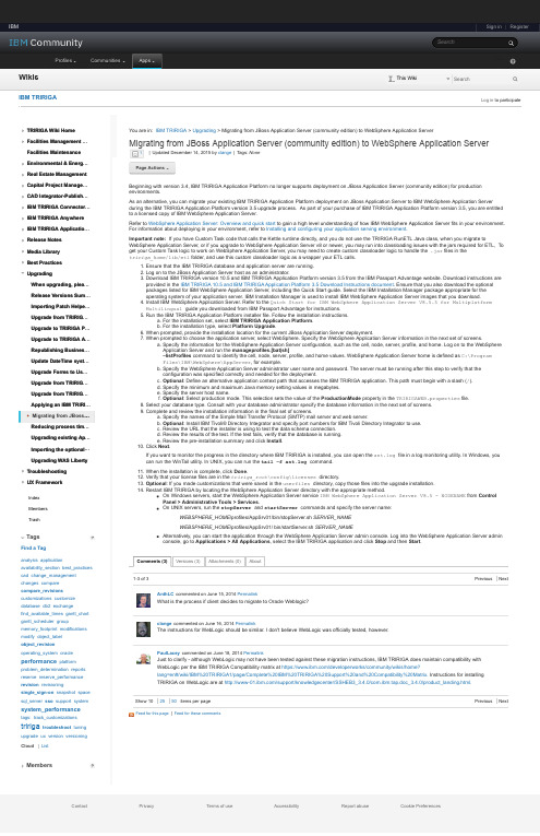
Sign in | Register IBMSearchIBM Profiles Communities Apps1-3 of 3Previous Next Show 102550 items per page Previous Next TRIRIGA Wiki HomeFacilities Management …Facilities MaintenanceEnvironmental & Energ …Real Estate ManagementCapital Project Manage …CAD Integrator-Publish …IBM TRIRIGA Connector …IBM TRIRIGA AnywhereIBM TRIRIGA Applicatio …Release NotesMedia LibraryBest PracticesUpgradingWhen upgrading, plea …Release Versions Sum …Importing Patch Helpe …Upgrade from TRIRIG …Upgrade to TRIRIGA P …Upgrade to TRIRIGA A …Republishing Busines …Update DateTime syst …Upgrade Forms to Us …Upgrade from TRIRIG …Upgrade from TRIRIG …Applying an IBM TRIRI …▪Migrating from JBoss …Reducing process tim …Upgrading existing Ap …Importing the optional …Upgrading WAS LibertyTroubleshootingUX FrameworkContact Privacy Terms of use Accessibility Report abuse Cookie Preferences You are in: IBM TRIRIGA > Upgrading > Migrating from JBoss Application Server (community edition) to WebSphere Application Server Feed for this page |Feed for these commentsSubmit WikisSearch This Wiki IBM TRIRIGA Log in to participate IndexMembersTrash TagsFind a Taganalysis applicationavailability_section best_practicescad change_managementchanges comparecompare_revisionscustomizations customizedatabase db2 exchangefind_available_times gantt_chartgantt_scheduler groupmemory_footprint modificationsmodify object_labelobject_revisionoperating_system oracle performance platformproblem_determination reportsreserve reserve_performancerevision revisioningsingle_sign-on snapshot spacesql_server sso support system system_performancetags: track_customizations tririga troubleshoot tuningupgrade ux version versioningCloud ListMembersMigrating from JBoss Application Server (community edition) to WebSphere Application Server |Updated December 14, 2015 by clange |Tags: None Page Actions 1Beginning with version 3.4, IBM TRIRIGA Application Platform no longer supports deployment on JBoss Application Server (community edition) for production environments.As an alternative, you can migrate your existing IBM TRIRIGA Application Platform deployment on JBoss Application Server to IBM WebSphere Application Server during the IBM TRIRIGA Application Platform version 3.5 upgrade process. As part of your purchase of IBM TRIRIGA Application Platform version 3.5, you are entitled to a licensed copy of IBM WebSphere Application Server.Refer to WebSphere Application Server: Overview and quick start to gain a high level understanding of how IBM WebSphere Application Server fits in your environment.For information about deploying in your environment, refer to Installing and configuring your application serving environment .Important note: If you have Custom Task code that calls the Kettle runtime directly, and you do not use the TRIRIGA RunETL Java class, when you migrate to WebSphere Application Server, or if you upgrade to WebSphere Application Server v8 or newer, you may run into classloading issues with the jars required for ETL, To get your Custom Task logic to work on WebSphere Application Server, you may need to create custom classloader logic to handle the .jar files in the tririga_home /lib/etl folder, and use this custom classloader logic as a wrapper your ETL calls.1.Ensure that the IBM TRIRIGA database and application server are running.2.Log on to the JBoss Application Server host as an administrator.3.Download IBM TRIRIGA version 10.5 and IBM TRIRIGA Application Platform version 3.5 from the IBM Passport Advantage website. Download instructions are provided in the IBM TRIRIGA 10.5 and IBM TRIRIGA Application Platform 3.5 Download Instructions document . Ensure that you also download the optional packages listed for IBM WebSphere Application Server, including the Quick Start guide. Select the IBM Installation Manager package appropriate for the operating system of your application server. IBM Installation Manager is used to install IBM WebSphere Application Server images that you download.4.Install IBM WebSphere Application Server. Refer to the Quick Start for IBM WebSphere Application Server V8.5.5 for Multiplatform Multilingual guide you downloaded from IBM Passport Advantage for instructions.5.Run the IBM TRIRIGA Application Platform installer file. Follow the installation instructions.a.For the installation set, select IBM TRIRIGA Application Platform .b.For the installation type, select Platform Upgrade .6.When prompted, provide the installation location for the current JBoss Application Server deployment.7.When prompted to choose the application server, select WebSphere. Specify the WebSphere Application Server information in the next set of screens.a.Specify the information for the WebSphere Application Server configuration, such as the cell, node, server, profile, and home. Log on to the WebSphere Application Server and run the manageprofiles.[bat|sh]–listProfiles command to identify the cell, node, server, profile, and home values. WebSphere Application Server home is defined as C:\Program Files\IBM\WebSphere\AppServer , for example.b.Specify the WebSphere Application Server administrator user name and password. The server must be running after this step to verify that the configuration was specified correctly and needed for the deployment.c.Optional : Define an alternative application context path that accesses the IBM TRIRIGA application. This path must begin with a slash (/).d.Specify the minimum and maximum Java memory setting values in megabytes.e.Specify the server host name.f.Optional : Select production mode. This selection sets the value of the ProductionMode property in the TRIRIGAWEB.properties file.8.Select your database type. Consult with your database administrator specify the database information in the next set of plete and review the installation information in the final set of screens.a.Specify the names of the Simple Mail Transfer Protocol (SMTP) mail server and web server.b.Optional : Install IBM Tivoli® Directory Integrator and specify port numbers for IBM Tivoli Directory Integrator to use.c.Review the URL that the installer is using to test the data schema connection.d.Review the results of the test. If the test fails, verify that the database is running.e.Review the pre-installation summary and click Install .10.Click Next .If you want to monitor the progress in the directory where IBM TRIRIGA is installed, you can open the ant.log file in a log monitoring utility. In Windows, you can run the WinTail utility. In UNIX, you can run the tail –f ant.log command.11.When the installation is complete, click Done .12.Verify that your license files are in the tririga_root \config\licenses directory.13.Optional : If you made customizations that were saved in the userfiles directory, copy those files into the upgrade installation.14.Restart IBM TRIRIGA by locating the WebSphere Application Server directory with the appropriate method.On Windows servers, start the WebSphere Application Server service IBM WebSphere Application Server V8.5 - NODENAME from Control Panel > Administrative Tools > Services .On UNIX servers, run the stopServer and startServer commands and specify the server name:WEBSPHERE_HOME /profiles/AppSrv01/bin/stopServer.sh SERVER_NAMEWEBSPHERE_HOME /profiles/AppSrv01/ bin/startServer.sh SERVER_NAMEAlternatively, you can start the application through the WebSphere Application Server admin console. Log into the WebSphere Application Server admin console, go to Applications > All Applications , select the IBM TRIRIGA application and click Stop and then Start .AnthLC commented on June 15, 2014 Permalink What is the process if client decides to migrate to Oracle Weblogic?clange commented on June 16, 2014 Permalink The instructions for WebLogic should be similar. I don't believe WebLogic was officially tested, however.PaulLacey commented on June 18, 2014 PermalinkJust to clarify - although WebLogic may not have been tested against these migration instructions, IBM TRIRIGA does maintain compatibility with WebLogic per the IBM TRIRIGA Compatibility matrix at https:///developerworks/community/wikis/home?lang=en#/wiki/IBM%20TRIRIGA1/page/Complete%20IBM%20TRIRIGA%20Support%20and%20Compatibility%20Matrix. Instructions for installing TRIRIGA on WebLogic are at /support/knowledgecenter/SSHEB3_3.4.0/com.ibm.tap.doc_3.4.0/product_ments (3)Versions (3)Attachments (0)About。
集特智能国产加固笔记本GEC-2602飞腾D2000
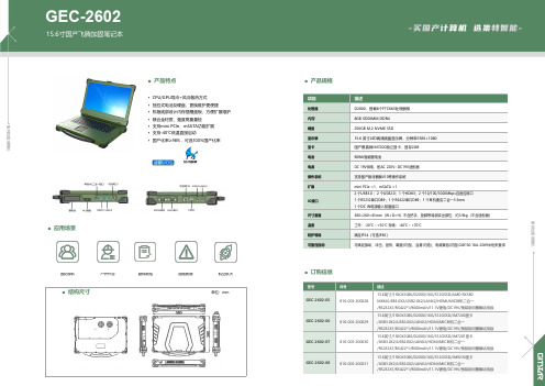
■产品规格项目描述处理器D2000,搭载8个FTC663处理器核内存8GB SODIMM DDR4硬盘256GB M.2NVME SSD显示屏15.6英寸LED高清液晶显示屏,分辨率1920×1080显卡国产景嘉微JM7200独立显卡,显存2GB电池90Wh智能锂电池电源DC19V供电,配AC220V~DC19V适配器操作系统支持国产银河麒麟V10等操作系统扩展mini PCIe×1,mSATA×1IO接口2个USB3.0;2个USB2.0;1个HDMI;2个10/100/1000Mbps自适应网口1个RS232串口DB9;1个RS422串口DB9;1个耳机麦克二合一3.5mm1个DC IN电源输入航插接口尺寸重量380×260×45mm(W×D×H)不含把手、垫脚等局部突出部位;约3.9kg(不含适配器)温度工作:-20℃~+50℃存储:-40℃~+70℃防护等级满足IP54(可选IP65)可靠性指标可满足振动、冲击、湿热、霉菌(可选)、盐雾(可选)、电磁兼容(可选)GJB150.18A-2009中相关要求■订购信息型号料号描述GEC-2602-05810-003-20002815.6英寸/1920X1080/D2000/16G/512GSSD/AMD RX580MXM/USB3.0X2/USB2.0X2/LANX2/HDMI/MIC耳机二合一/RS232X1/RS422*1/9000mAh/11.1V锂电/DC19V/预装银河麒麟试用版GEC-2602-06810-003-20002915.6英寸/1920X1080/D2000/16G/512GSSD/JM7200显卡/USB3.0X2/USB2.0X2/LANX2/HDMI/MIC耳机二合一/RS232X1/RS422*1/9000mAh/11.1V锂电/DC19V/预装银河麒麟试用版GEC-2602-07810-003-20003015.6英寸/1920X1080/D2000/16G/512GSSD/JM7201显卡/USB3.0X2/USB2.0X2/LANX2/HDMI/MIC耳机二合一/RS232X1/RS422*1/9000mAh/11.1V锂电/DC19V/预装银河麒麟试用版GEC-2602-08810-003-20003115.6英寸/1920X1080/D2000/16G/512GSSD/JM9230显卡/USB3.0X2/USB2.0X2/LANX2/HDMI/MIC耳机二合一/RS232X1/RS422*1/9000mAh/11.1V锂电/DC19V/预装银河麒麟试用版■产品特点•CPU/GPU导冷+风冷散热方式•抽拉式电池及硬盘,更换维护更便捷•机箱底部设计内存插槽盖板,方便扩展维护•镁合金材质,强度高重量轻•支持mini PCIe、mSATA功能扩展•支持-40℃低温直接启动•国产化率≥98%,可选100%国产化率■应用场景国防部队户外作业勘探测绘道路救援航空航天■结构尺寸单位:mm集特加固便携机集特加固便携机。
【CN305367224S】行车记录仪FHD6900W【专利】

1/1 页
3
( 19 )中华人民 共和国国家知识产权局
( 12 )外观设计专利
(21)申请号 201930161084 .0
(22)申请日 2019 .04 .10
(73)专利权人 东莞市德才电子科技有限公司 地址 523000 广东省东莞市虎门镇小捷滘 捷东工业区
(72)设计人 刘佳武
(74)专利代理机构 广州市南锋专利事务所有限 公司 44228
外观设计图片或照片
1/1 页
主视
立体图2
2
CN 305367224 S
简 要 说 明
1.本外观设计产品的名称:行车记录仪(FHD6900W)。 2.本外观设计产品的用途:本外观设计产品用于记录行车轨迹。 3.本外观设计产品的设计要点:产品的整体形状设计。 4.最能表明本外观设计设计要点的图片或照片:主视图。
代理人 罗晓聪
(51)LOC(12)Cl . 16-01
(10)授权公告号 CN 305367224 S (45)授权公告日 2019.09.27
( 54 )使用外观设计的产品 名称 行车记录仪(FHD6900W)
图片或照片 8 幅 简要说明 1 页
CN 305367224 S
主视图
CN 305367224 S
- 1、下载文档前请自行甄别文档内容的完整性,平台不提供额外的编辑、内容补充、找答案等附加服务。
- 2、"仅部分预览"的文档,不可在线预览部分如存在完整性等问题,可反馈申请退款(可完整预览的文档不适用该条件!)。
- 3、如文档侵犯您的权益,请联系客服反馈,我们会尽快为您处理(人工客服工作时间:9:00-18:30)。
(19)【発行国】日本国特許庁(JP)
(45)【発行日】令和2年3月2日(2020.3.2)
(12)【公報種別】意匠公報(S)
(11)【登録番号】意匠登録第1653900号(D1653900)
(24)【登録日】令和2年2月10日(2020.2.10)
(54)【意匠に係る物品】自動車用チャイルドシート
(52)【意匠分類】D7-251
(51)【国際意匠分類(参考)】Loc(11)Cl.6-01
【Dターム】D7-251A
(21)【出願番号】意願2019-5839(D2019-5839)
(22)【出願日】平成31年3月19日(2019.3.19)
(31)【優先権主張番号】005649928-0004
(32)【優先日】平成30年9月19日(2018.9.19)
(33)【優先権主張国】欧州連合知的財産庁(EM)
(72)【創作者】
【氏名】マルチン イムリフ
【住所又は居所】チェコ国,147 00 プラハ,ナト コステレム 725/8
(72)【創作者】
【氏名】イジー プシビル
【住所又は居所】チェコ国,147 00 プラハ,ナト コステレム 725/8
(73)【意匠権者】
【識別番号】318017039
【氏名又は名称】ゲーベー ゲゼルシャフト ミット ベシュレンクテル ハフツング
【住所又は居所】ドイツ連邦共和国,95448 バイロイト,リーディンガー シュトラーセ 18(74)【代理人】
【識別番号】100099759
【弁理士】
【氏名又は名称】青木 篤
【審査官】綿貫 浩一
【斜視図】。
