块状物品推送机设计说明书
机械设计课程设计说明书1

设计题目:块状物品推送机的机构综合与结构设计在自动包裹机的包装作业过程中,经常需要将物品从前一工序转送到下一工序。
现要求设计一用于糖果、香皂等包裹机中的物品推送机,将块状物品从一位置向上推送到所需的另一位置。
设计数据与要求(1) 向上推送距离H=120mm,生产率为每分钟推送物品120件;(2) 推送机的原动机为同步转速为3000转/分的三相交流电动机,通过减速装置带动执行机构主动件等速转动;(3) 由物品处于最低位置时开始,当执行机构主动件转过1500时,推杆从最低位置运动到最高位置;当主动件再转过1200时,推杆从最高位置又回到最低位置;最后当主动件再转过900时,推杆在最低位置停留不动;(4) 设推杆在上升运动过程中,推杆所受的物品重力和摩擦力为常数,其值为500N;设推杆在下降运动过程中,推杆所受的摩擦力为常数,其值为100N;(5) 使用寿命10年,每年300工作日,每日工作16小时;(6) 在满足行程的条件下,要求推送机的效率高(推程最大压力角小于350),结构紧凑,振动噪声小。
总体图为了减少实物的质量故机壳选取Al作为材料设计机构图设计实体图减速系统设计本机构原动件为一高速电机,其转速为3000r/min,但我们所需要的转速是120r/min,所以要减速。
对于减速装置我们采用皮带加齿轮的方法。
第一级降速是用皮带减速,减为240r/min。
第二级是用齿轮减为120r/min。
皮带传动机构设计分析如下:带传动的优点:(1)适用于中心距较大的传动;(2)带具有良好的挠性,可缓和冲击,吸收振动;(3)过载时带与带轮间会出现打滑,打滑虽然使传动失效,但可防止损坏其他零件;(4)机构简单、成本低廉。
带传动的缺点:(1)传动的外廓尺寸较大;(2)需要张紧装置;(3)由于带的滑动,不能保证固定不变的传动比;(4)带的寿命较短;(5)传动效率较低。
通常,带传动适用于中小功率的传动。
目前V带传动应用最广,一般带速为V=5≈25m/s,传动比i≦7,传动效率0.9至0.95.皮带传动设计主要是采用两个半径不一的皮带轮来实现。
包装机械_供送与计量
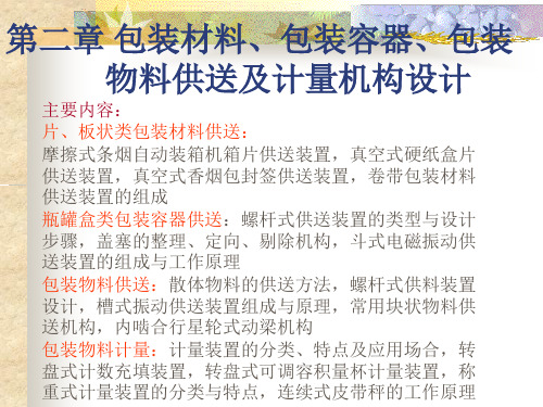
供送机构是包装设备的重要组成部分,其结构及工作 性能决定着设备的自动化水平及生产率,并影响着设备的 总体布局。
包装机械的供送对象一般是指被包装物料、包装容器 和包装材料等。
第一节 板、片材供送机构
(一)纸片摩擦拨出供送装置 图2-1所示为纸片摩擦拨出供送装置。工作时,先将纸 片放入纸库9内,纸的后端由顶针5顶住,前端由托纸辊 7托住,托纸辊7在传动系统的带动下作等速回转运动, 当拨纸块1和纸片接触时带纸向前运动,纸片被旋转的 下纸辊11和从动压纸辊10牵引,通过导向钢片13的导向, 使纸成垂直的方向输入接纸钩15内。包装物品推送时, 纸片就裹在外面,经后面的包装工序完成包装。当机器 发生故障不需要纸片下落时,把升纸钢丝2摆动一定的 角度将纸抬起,使之与拨纸辊上的弹性拨片完全脱离接 触而停止供送。如果纸片下落位置不符合要求时,可调 整接纸钩的调节螺钉14。该装置对称分布的两根顶纸针 可能会拉破纸片,所以对商标纸忌用。对质地较软、摩 擦较大的纸片也不适用。Leabharlann 第三节 瓶、罐及盒类包装容器
的供送装置
灌装机、封罐机、装盒机等包装机在生产过程中,均需把瓶、
罐、盒等包装容器按包装工艺要求的路线、速度、间距和状态供送 到包装工位,与物料充填机构配合,完成物料充填,以满足确定的 工艺条件、生产能力及布局要求。啤酒瓶、易拉罐、三片罐等刚性 容器的供送机构一般由容器储存仓、输送链(带)、拨瓶轮、供送 螺杆等组成;纸盒等形状规整的包装容器一般采用输送链(带)和 推板相结合的供送方式;安瓿瓶、西林瓶等小规格的包装容器,一 般采用储存盘、输送链(带)、拨瓶轮或动梁机构等组成的供送方 式。
1.等螺距螺杆供送装置
图3-45水平等螺距螺杆供送装置
1-理瓶存槽 2-供送螺杆 3-输送链带 4-侧向导轨
篝条推送器操作手册说明书
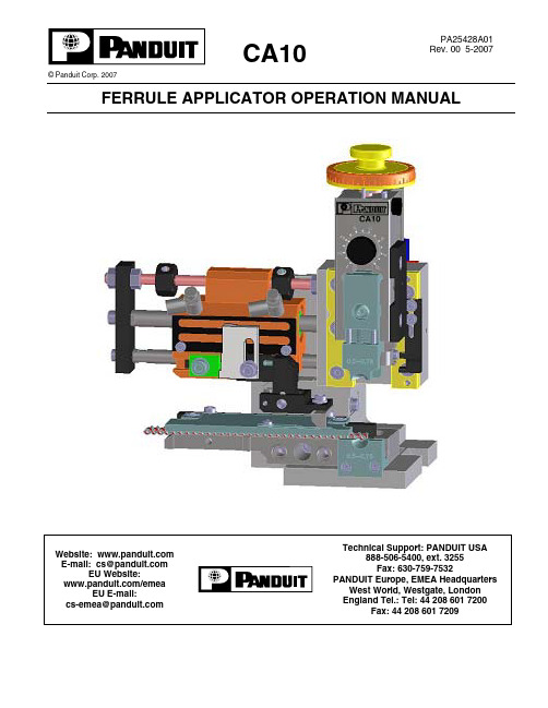
CA10© Panduit Corp. 2007FERRULE APPLICATOR OPERATION MANUALPA25428A01Rev. 00 5-2007TABLE OF CONTENTSREGULATIONS (3)A. SAFETY1. ABOUT THIS OPERATION MANUAL (4)INFORMATION (4)1.1 IMPORTANT1.1.1 Manufacturer and Contact Information (4)Market (4)1.1.2 Target1.1.3 Obligation to read (4)1.1.4 Validity (4)Contents and Purpose (4)1.1.5 Regarding1.1.6 L ocation (4)1.2 L EGEND (4)1.3 SYMBOLS (5)Instructions (5)1.3.1 Safety1.3.2 Codes (5)INSTRUCTIONS (6)2. GENERALCONNECTIONS (6)2.1 SEA L EDSCREWDESCRIPTION (6)3. PRODUCT3.1 APP L ICATION (6)3.2 GENERA L INFORMATION (6)3.3 TECHNICA L SPECIFICATIONS (7)4. ADJUST M ENTS (8)4.1 CHANGING THE DIAMETER RANGE (8)OPERATION (9)INTO5. PLACING5.1 SETTING UP THE APPLICATOR (9)Setting (9)5.1.1 Basicthe Applicator (9)5.1.2 Installing5.1.3 Check for proper Feeding of the Dereeler (10)5.1.4 Adjust the Crimp Parameters (10)5.1.5 Pneumatic Connection (10)5.1.6 Applicator Head (11)5.2 ADJUSTINGTHE APPLICATOR (11)theCrimp Height (11)5.2.1 Setting5.2.2 Ferrule Feed (12)THE APPLICATOR (13)5.3 DISMOUNTING6. TROUBLESHOOTING (14)6.1 GENERAL (14)6.2 CHECKLIST FOR TROUBLESHOOTING (14)7. M AINTENANCE (16)7.1 GENERA L WORK (16)7.2 CHANGE OF WEARABLE PARTS (17)7.2.1 Anvil (17)7.2.2 Crimp Die (18)Part Ejector (19)7.2.3 Mechanical8. APPENDIX (20)MICROLUBE GBU-Y 131 (20)8.1 L UBRICATINGGREASEA. Safety RegulationsA1.SymbolsPlease follow exactly the work and processes marked with this pictogram. Failure to do so may result in death or severe injury.Please follow exactly the work and processes marked with this pictogram. Failure to do so may lead to minor injuries and to damage to the machine.A2. Product descriptionThe PANDUIT CA10 is a new generation crimp applicator for use in both automatic or semi-automatic benchtop crimping machines. With its innovative uni-body design, the CA10 ferrule applicator guarantees highest precision and is universally deployable in all standard crimping presses.A3. ResponsibilitiesThe machine operator is responsible for ensuring that every employee who uses the PANDUIT CA10 has received training in accordance with these operating instructions (initial operation, operation, maintenance). The training of the operating personnel must include the following:• Purpose of the machine(see section A2 Product description).• Danger areas(see section A4 Personal qualifications).• Safety instructions(see Default A6 Safety requirements).• Operating the machine in accordance with these operating instructions.A4. Personal qualificationsTo ensure that all instructions are understood, training must take place in the language of the operating personnel. This means that the following personnel qualifications are required:Assembly,initial operation,instructionTechnical specialist staff who have a good command of English.Operation Trained staff in accordance with A3 Responsibilities.Maintenance, service Technical specialist staff who havea good command of English.A5. Danger areas• The whole area of the processing spaceunderneath the Plexiglas cover- Danger due to the crimp process of theapplicator- Danger from crimp stroke• The entire interior area of the machine andthe metal casing:- Danger from electrical current- Danger from mechanical moving partsA6. Safety requirements• This machine has been designed inaccordance with the European StandardEN12100-1 & 12100-2.• Never operate the machine in environmentswhere there is a risk of fire or explosion.• The machine must only be operated inrooms that are dry and free from dust.• Never operate the machine without itsprotective covers.• Never work on the machine without wearingeye protection.• Disconnect the machine from the electricaland/or compressed air supply beforecarrying out any maintenance work.• Never operate the machine with the mainground disconnected.• Do not make any modifications to themachine and only utilise it for its intendedpurpose according to Paragraph A2 Productdescription. Other applications are onlypermitted with the written approval of themanufacturer. The manufacturer will acceptno liability for damage resulting from thedisregard of this regulation.• Never operate the machine without firsthaving read through and understood allinstructions.• Repair work may only be carried out byauthorized persons who have been speciallytrained for this work.• Ensure if you work on the machine that longhair is not worn loose, and do not wearloose clothing or ornaments that couldbecome caught in the moving parts of themachine.• Only use the lubricant that was deliveredwith this machine according to theseoperating instructions.1. ABOUTOPERATION MANUALTHISWith the PANDUIT CA10 you have acquired a high-performance applicator for use in efficientcrimping of ferrules in a high quality standard.INFOR M ATION1.1 I M PORTANT1.1.1 Manufacturer and Contact AddressSee Cover PageM arket1.1.2 TargetOperator, see chapter A4 Personal Qualifications (Page 3)1.1.3 Obligation to readAs operator and user you are obliged to read and understand this manual particularlythe chapter A. Safety Regulations (Page 3) before commissioning the CA10applicator. It is about your own safety!Should you have any questions or feel unsure about anything, please contact your localPANDUIT distributor.1.1.4 ValidityThis manual is only valid for the PANDUIT CA10 applicator.1.1.5 Regarding Contents and PurposeThis Operation Manual contains all the relevant information regarding assembly,function, commissioning and operation of the CA10 applicator.1.1.6 LocationThis manual must always be available to the Group Leader / Fitter on site.1.2 LEGENDDimensions All measurements in this manual are given ininches and millimeters.Cross references Cross references are indicated in the text withcolor (for example) 1.2 Legend (Page 4)1.3 SY M BOLSInstructions1.3.1 SafetyTo avoid any injuries or material damage it is essential that you read and fullyunderstand the following safety symbols:1.3.2 Codes2. GENERALINSTRUCTIONS2.1 SEALED SCREW CONNECTIONSDESCRIPTION3. PRODUCT3.1 APPLICATIONThe CA10 applicator is designed for processing reel feed ferrules for wire cross sections from AWG 20 - AWG 14 (.5 mm2- 2.5 mm2 ).The applicator is available with a pneumatic feeding system. The pneumatic feeding is activated by an integrated valve.INFOR M ATION3.2 GENERALThe wire crimp height is independently adjustable as is the ferrule feeding. The feed stroke is set by an adjustable plate.To achieve optimum crimping results, properly cut off wire ends and proper insertion of the wire into the applicator is necessary.3.3 TECHNICALSPECIFICATIONSDescriptionSide Feed (mechanical / pneumatic)Applicator stroke 1.57 in. / 1.18 in. (40mm / 30mm)Wire size range AWG 20-14 (.5 mm2- 2.5 mm2 )Range: .0394 in. (1 mm)Wire crimp heightadjustmentIncrements: .0008 in. (0.02 mm)Feed Adjustable Width: 5.3 in. (135 mm)Depth: 4.3 in. (110 mm)DimensionsHeight: 6.9 in. (175 mm)Weight: Approx. 5.9 lbs. (2.7 kg)4. ADJUST M ENTS4.1 CHANGING THE DIAMETER RANGETo use the applicator with other ferrule diameters, the funnel, the crimp die and the anvil must be changed. The following diameter ranges are available:0.5 to 0.751.0 to 1.52.0to 2.51. Loosen funnel (B) and anvil (C) with both screws (A) and replace with new parts (thediameter range is engraved on the funnel and the anvil).Fig. 4.1aBCA2.Loosen funnel (B), spacer (C) and die (D) with screw (A) and replace with new parts (the diameter range is engraved on the funnel and the die).Fig. 4.1b3. Check if feed adjustment in chapter 5.2.2 Ferrule Feed (Page 12) corresponds with above parts.4.For further adjustments see description for standard applicators.5. PLACING INTO OPERATION5.1SETTING UP THE APPLICATORThe following procedure describes the best way to mount and set up the applicator for yourproduction.5.1.1 Basic SettingBefore mounting the applicator, the following adjustments are to be verified or made: – Check and if necessary, adjust the ferrule feed according to chapter 5.2.2 Ferrule Feed (Page 12)ADC5.1.2. Installing the ApplicatorMount applicator according to the Operation Manual of the corresponding crimpmachine.5.1.3 Check for proper Feeding of the Dereeler5.1.4 Adjust the Crimp ParametersIf the crimp values are not yet set, please refer to chapter4.1 Changing the Diameter Range (Page 8)5.1.5 PneumaticConnectionThe air supply for the pneumatic feed from the PANDUIT CP-871 press can beconnected to the throttles (A & B) of the applicator cylinder. The external air supplyshould be set to .6 MPa (~ 85 PSI). The normally open port on the CP-871 should be connected to throttle (B).BFig. 5.1.55.1.6 ApplicatorHeadFig. 5.1.65.2 ADJUSTING THE APPLICATOR5.2.1 Setting the Crimp HeightThe applicator shut height is adjusted by setting the graduated collar (F) (see Fig. 5.2.2on Page 12). The recommended letter setting and crimp measurement for each ferrulesize is indicated on the product reel. The graduated collar (F) should be initially turnedto the recommended letter setting for size of the ferrule. A test crimp should be made ona ferrule with the appropriate gauge wire loaded into it. The crimped ferrule should thenbe measured across the dimension shown in the figure below.Fig. 5.2.1The measured number should then be compared to the required measurement shownon the product reel. If necessary, adjust the graduated collar (F) and repeat the aboveprocess until the required dimension is achieved. Rotate clockwise to increase heightand rotate counterclockwise to decrease height.5.2.2 Ferrule Feed– The feed finger moves the contact when the applicator opens.– The speed is set by means of the two pneumatic throttles (A & B, see Fig. 5.1.5 on Page 10).1. Adjust part (A) to the corresponding ferrule diameter (observe engraved scale).2. Re-position finger (D).3. Lift break (B) and finger (D).4. Load ferrules under break (B) along guide surface until first ferrule is in die crimparea.5.Adjust anti-backup (C) to make contact with closest ferrule so that the anti-backup (C) is putting pressure on ferrule sleeve.Fig. 5.2.2DBEF5.3 DISMOUNTING THE APPLICATORTo further assure that the crimp height adjustment setting does not change, a lock screw (B) can be mounted. 1. The lock screw (included) is to be mounted and tightened prior to removing theapplicator from the machine. By doing so, locking pin (A) is blocked and the crimp height adjustment is additionally secured.2. Remove the applicator from the machine and clean.Fig. 5.3AB6. TROUBLESHOOTING6.1 GENERALThe information in this chapter should help to identify and eliminate occasional machine faultsquickly. If you cannot eliminate the fault yourself, please contact your local PANDUITrepresentative.6.2 CHECKLIST FOR TROUBLESHOOTINGPROBLEM POSSIBLECAUSE SOLUTIONSystem will not operate. A. Air hose not connected to airsource.B. Press regulator switch is turned“OFF”.A. Connect air hose to air source.B. Turn press regulator switch “ON”.Parts will not feed into crimping area. A. Flow control valve on air cylinderis fully closed.A. With a small screwdriver, turn theflow control set screwcounterclockwise, 4 full rotations.Parts are not being positioned correctly between die inserts--overfeed. A. Incorrect die inserts being usedfor the parts being terminated.B. Flow control valve on air cylinderis fully open.C. Air pressure to CA10 Applicator isabove .6MPa (85 PSI).D. Trigger holder set to wrong ferrulesize.A. Check product reel forappropriate die size.B. With a small screwdriver, turn theflow control set screw clockwise,until the proper feed is achieved.C. Adjust air pressure to .6MPa (85PSI).D. Adjust trigger holder to thecorrect product size.Parts are not being positioned correctly between die inserts--underfeed. A. Excessive tension on parts reel.B. Incorrect die inserts being usedfor the parts being terminated.C. Air pressure to CA10 Applicator isbelow .6MPa (85 PSI).D. Flow control valve on the aircylinder is nearly fully closed.E. Air lines to slide are installedbackwards.F. Trigger holder set to wrong ferrulesize.A. Check parts reel for binding.B. Check product reel forappropriate die size.C. Adjust air pressure to .6MPa (85PSI).D. With a small screwdriver, turn theflow control set screwcounterclockwise until properfeed is achieved.E. Switch hoses in flow control.Normally open air line on rightside of CP-871 valve should beconnected to CA10 flow controlon right side of air cylinder.F. Adjust trigger holder to correctferrule size.Unacceptable crimps--poor cut-offs. A. Incorrect die inserts being usedfor the parts being terminated.B. Die inserts are worn or damaged.C. Anti-backup plate is incorrectlypositioned.D. Blade is worn or damaged.A. Check product reel forappropriate die size.B. Replace die inserts.C. Position anti-backup correctly(see section 5.2.2 on Page 12).D. Replace blade.6.2 CHECKLIST FOR TROUBLESHOOTING (continued)PROBLEM POSSIBLECAUSE SOLUTIONUnacceptable crimps—smashed ferrules. A. Incorrect die inserts being usedfor the parts being terminated.B. Crimp height adjustment dial isset incorrectly.C. Die inserts are worn and crimpheight adjustment dial is at lowestsetting.D. Die insert screws are not snug.E. Improper press adjustment.A. Check product reel forappropriate die size.B. Adjust dial to appropriate setting(refer to product reel).C. Replace die inserts.D. Tighten die insert screws.E. Position the adjustment dial onCP-871 to the 0 position.Low pullout A. Crimp height adjustment dial isset incorrectly.B. Incorrect die inserts being usedfor the parts being terminated. A. Adjust dial to appropriate setting(refer to product reel).B. Check product reel forappropriate die size..Ferrules are sticking in die. A. Crimp height adjustment dial isset incorrectly.B. Part ejector missing or damaged. A. Adjust dial to appropriate setting(refer to product reel).B. Install new part ejector (seesection 7.2.3 on Page 19).7. M AINTENANCEWORK7.1 GENERALThe applicator must be cleaned daily (removal of dust, crimping waste and other foreignparticles). Gliding surfaces (B) and feed finger (A) must be greased after 100,000 cycles with lubricating grease, see 8.1 Lubricating grease Microlube GBU-Y 131 (Page 20).Fig. 7.17.2CHANGE OF WEARABLE PARTS7.2.1 Anvil1. Remove the applicator from the machine and slide out the upper part of theapplicator.2. Remove the two hex socket screws (A) that hold the anvil assembly.3. Remove the lower funnel (B). 5. Remove the anvil (C) from the groove of the base plate. 6. Clean the anvil support area of the base plate (D) 7. Replace anvil (C) and/or lower funnel (B). If needed, clean existing parts. 8. Place anvil (C) and lower funnel (B) into groove in base plate. 9. Place socket head screws (A) through lower funnel (B) and anvil (C), and intoapplicator.10. Tighten screws (A).Fig. 7.2.1Fig. 7.2.1aFig. 7.2.1bFig. 7.2.1cBD7.2.2 Crimp Die1. Dismount the applicator from the machine and remove the upper part of theapplicator.2. Loosen the hex socket screw (A) that holds the crimp die assembly on the dieholder.3. Replace the crimp die or dies. Clean the die holder.4. Mount the parts.5. Affix the crimp die assembly with the hex socket screw (A).6. Remount the upper part of the applicator.7. Remount applicator in the machine according to chapter5.1 Setting up the Applicator (Page 9).Fig. 7.2.2A7.2.3Mechanical Part EjectorThe part ejector may need to be cleaned or replaced.1. Remove applicator from machine and slide out upper part of applicator.2. Loosen the socket hex screw (A) that holds the crimp die assembly on the dieholder.3. Remove the crimp die assembly.4. Remove socket head screw (C) from side of applicator.5. Remove mechanical part ejector (B).6. Replace with new ejector (B) and fasten with socket head screw (C).7. Return crimp die assembly to applicator and fasten with socket hex screw (A). 8. Place upper part of applicator back into applicator and return to machine.Fig. 7.2.3CCA10 OPERATION MANUALPage: 20 of 20 8. APPENDIX8.1 LUBRICATING GREASE MICROLUBE GBU-Y 131。
块状物品推送机构的设计

电动机的功率及满载转速分析
电动机效率η1 =73% 单头蜗杆传动效率η2= 75%
V带传送效率η3=96%
在一个周期T=0.5s
凸轮传动效率η4= 90%
移动副传动效率η5= 85%
阻力功w=(500*120+100*120)*0.001=72 J
阻力功率p1=w/T=144J/s 机构总效率η=η1*η2*η3*η4*η5=0.402
设计前景
输送机是一定的线路上连续输送物料的物料搬运机械,又称 连续输送机。输送即可进行水平、倾斜和垂直输送,也可组成 空间输送线路,输送线路一般是固定的。输送机输送能力大, 运距长,还可在输送过程中同时完成若干工艺操作,所以应用 十分广泛。可以单台输送,也可多台组成或与其他输送设备组 成水平或倾斜的输送系统,以满足不同布置形式的作业线需要。 本文主要是对用于糖果、香皂等包裹机中的物品推送机进行设 计,将块状物品从一位置向上推送到所需的另一位置,加强贵 机械设计的理解。 在自动包裹机的包装作业中,经常需要将物品从前一个工序推 送到下一个工序,块状物品推送机已经广泛运用到了物品包装 工序以及各种其它机构中,并发挥着不可替代的作用。
基本尺寸的设计:
凸轮基圆半径r0=100mm, 推程h=120mm,滚子半径 rb=18mm蜗杆m=4,头数 为一,蜗轮m=4,V带准 长度250;带轮1基准直 径=50,外径=52.2槽型 为 Y;带轮2基准直径=20 ,外径=23.2 槽型为 Y;
带轮
选择V带型B种V型带开口传动线绳结构
机构驱动力功率p2=p1/η=0. 3764 J/s=1.289kw
电动机功率应确定为1.8 kw ;电动机满载转速为 3000r/mm
机械原理课程设计说明书
4. 1) 2) 3)
4) 5) 6) 7) 5.
6.
方案一
凸轮机构:其结构简单,易于设计与制造,能使从动件获得较为复杂的运动规律。 因为从动件的运动规律取决于凸轮轮廓曲线,所以在应用时只要根据从动件的运动 规律来设计凸轮的轮廓曲线就可以了。凸轮机构广泛应用于各种自动机械、仪器和 操控装置。凸轮机构之所以得到如此广泛的应用,主要是由于凸轮机构可以实现各 种复杂的运动要求,而且结构简单、紧凑。如图 4-所示的凸轮机构,凸轮以等角 速度回转,它的轮廓驱使从动件,可使推杆实现任意的运动规律,但行程较小。
缓和冲击, 吸收振动; (3) 过载时带与带轮间会出现打滑, 打滑虽然使传动失效, 但可防止损坏其他零件; (4)机构简单、成本低廉。 带传动的缺点: (1)传动的外廓尺寸较大; (2)需要张紧装置; (3)由于带 的滑动,不能保证固定不变的传动比;(4)带的寿命较短; (5)传动效率较低。 通常,带传动适用于中小功率的传动。目前 V 带传动应用最广,一般带速为 V=5≈25m/s,传动比 i≦7,传动效率 0.9 至 0.95.
摘要 我们小组设计的是包裹机包装作业过程中的块状物体推送机,其工作时要有固定的推 送行程和工作速度。我们所设计的结构是固定凸轮-连杆机构,由电动机驱动,完全由 机械结构控制实现工作要求,其工作状态稳定,效率高。本书对其设计过程做具体说 明,先对块状物体推送机的工作过程进行解析、研究,对设计要求做好全面分析,明 确设计方向;然后提出几组设计方案,对其进行分析比较,再提出总的设计方案;确 定方案后进行具体的设计,以使推送机的运动过程达到设计要求,主要包括各个构件 的尺寸大小和质量的确定,最后还要通过速度、加速度、各个构件的受力情况、压力 角等进行分析,进一步优化设计,达到减小功耗,稳定工作状态的目的。设计工作结 束后进行总结,将设计过程中遇到的问题进行总结,对设计作品做出评价。 目录 一、 课程设计任务书 设计题目 工作原理及工艺动作过程 相关数据及设计要求 设计任务 设计方案提示 二、 摘要 三、 目录 四、 课程设计题目简介 五、运动循环图 六、执行机构的选择和评价 七、机械传动系统设计计算 八、机械运动方案简图的绘制 九、机械运动系统机构的计算 十、机构运动分析
块状物品推送机

电劢机的功率及满载转速分析:
电劢机效率η1 =73%
V带传送效率η3=96% 移劢副传劢效率η5= 85%
单头蜗杆传劢效率η2= 75%
凸轮传劢效率η4= 90%
在一个周期T=0.5s
阻力功w=(500*120+100*120)*0.001=72 J
阻力功率p1=w/T=144J/s
机构总效率η=η1*η2*η3*η4*η5=0.402 机构驱劢力功率p2=p1/η=0. 3764 J/s=1.289kw 电劢机功率应确定为1.8 kw ;电劢机满载转速为 3000r/mm
电劢机,通过减速
定子绕组
装置带劢执行机构
主劢件等速转劢。
转轴
电机不减速器的连
接采用V带连接。
接线盒 转子
减速系统设计:
采用皮带加齿轮的减速装置。第一级降速将 原速用皮带减速,减为240r/min。第二级是
用齿轮减为120r/min。
优点:传劢机构简单、成
本低廉;具有良好的挠性,
可缓和冲击,吸收振劢;过 载时带不带轮间会出现打 滑,可防止损坏其他零件。
Page 20
飞轮的设计:
要使执行机构主劢件的速度波劢系数小于3%, 则要在执行机构主劢件轴上增加飞轮: 设计所飞轮的JF应满足: δ≤[δ]=0.03 即:δ=△Wmax /[(Je+JF )] ≤[δ] 得:JF≥△Wmax/([δ]) -Je 当Je<< JF ,故Je可以忽略, 于是有: JF≥△Wmax/([δ]) 用转速n表示:JF≥900
推杆运劢规律分析:
由物品处于最高位置是开始,当执行机构 主劢件转过150°时,推杆从最低位置运劢到 最高位置,当主劢件再转过120°时,推杆从 最高位置又回到最低位置,最后当主劢件再 转过90°时,推杆在最低位置保持静止。
块状物品推送机的机构综合与结构设计毕业答辩ppt
结构设计
凸轮设计 凸轮是一种具有曲线轮廓或凹槽的构件, 它通过与从动件的高副接触,在运动时可以 使从动件获得连续或不连续的任意预期运动。
重庆工商职业学院 2013级机电一体化
机构运动仿真
重庆工商职业学院 2013级机电一体化
加工
• 3D打印
• 3D打印技术(英语:3D printing),即快 速成形技术的一种,它是一种以数字模型 文件为基础,运用粉末状金属或塑料等可 粘合材料,通过逐层打印的方式来构造物 体的技术。
重庆工商职业学院 2013级机电一体化
3D打印产品零件图
重庆工商职业学院 2013级机电一体化
结论
• 本次设计具有一定的难度,它需要对所学知识十分 熟悉,并且还需要对于没学的知识进行自学来完成 设计。在实际过程中我们使用了CAD、UG等制图软 件,查阅了很多与物块推送机构的相关资料,了解 到了物块推送需要较高的效率、稳定性,噪音小、 使用效率高的特点。本次设计我们学到了很多,首 先在设计时,我们学会了综合考虑,通过对比的方 法选择最优方案,学会了发现问题与解决问题。当 然在设计过程中,团队合作精神是非常重要的,我 们四人明确分工,各自完成好自己的设计内容。当 中我们也发现了我们的不足,在此过程中,我们更 加完善我们自身的不足之处。相信在以后的设计中, 我们会做的更好。
块状物品推送机的机构综合与 结构设计
答辩人 黄思豪 周大兵 舒友翠 殷盛瑜 专 业 机电一体化(计算机辅助方向) 机电一体化(计算机辅助方向) 机电一体化(数控方向) 机电一体化(数控方向) 指导教师 :李海翔
答辩时间 :2015年12月2日
方案设 计
• 方案一 • 方案二 • 方案三
第二章 供送装置

二、典型的散体供送装置 散体供送装置,依其主体运动的方式可分为旋转式、摆动
四、拨轮式供送装置
图2.4 所示为星形拨 轮供送装置,一般用作供 送瓶罐类包装容器。它 主要由星形拨轮1、3,输 送链带2,主传送链带4和 固定的圆钢导轨5等组成。 主传送链带并列两条(送 盒的一条未画),均属复 式板链结构。根据物件 的体形大小及盒子的外 廓尺寸,可在一定范围内 分别调整放瓶挡板及放 盒夹板的间距,以提高该 机的通用能力。
图2.1 链带式供送机构简图 1-台面板 2-挡板 3-料库活门 4-推板比较简单紧凑,所占空间不大,又易同其 他传动装置联动,只是运动惯性较强,工作速度不能过高。
三、动梁式供送装置
图2.3所示为双曲柄式动梁供送装置。动梁4与定梁3 等长,动梁作等速的正圆平动。两梁均有等间距的V形槽用 来支撑和拖动被供送的圆柱形或长条形(如干电池、安瓿 等)物件。考虑到物件是作间歇的圆弧线运动,因而需控制 适当的主动轴转速,以尽量减缓起落时所产生的冲击力。 若保持槽间距一定而仅改变被供送物件的动停比,则应调 整两曲柄2的回转半径及定梁的上下位置,从这一点看,双曲 柄式动梁机构比较灵活。
图2.7 特种变螺距螺杆供送装置
(a)合流 (b)分流 (c)转向 (d)翻身
第二节、散体物品的供送装置
一、散体的基本形态
散体物品是指由确定数量的一种或数种个体所 组成的松散聚集物。它具有一定的流动性,但易吸取 空气中的水份受潮,粘性增加甚至结块,使其物理特性 变化。根据散体的基本物性,大体可分为三个基本形 态。
块状物品推送机设计说明书
机械原理课程设计说明书1机械原理课程设计题目:块状物品推送机班级:2012级机械设计制造及其自动化2班 组员:胡鑫亮(组长) 刘润华 张鹏飞 郭日哲李东杰 黄玉指导教师: 康辉梅工程与设计学院2014年6月12日目录分工明细 (3)一.设计任务书 (4)1.设计题目 (4)2. 设计条件及要求 (4)3。
设计任务 (4)二.方案选择 (5)方案一 (5)方案二 (6)方案三 (6)三。
基本参数 (7)1.凸轮设计 (7)2.带传动 (8)3.蜗轮蜗杆 (9)4.减速系统设计 (9)5.电动机性能要求 (10)6.电动机的功率及满载转速分析 (10)四.滚子从动件各个阶段相关方程 (10)位移速度及加速度变化曲线 (12)编程结果 (15)三维模型 (18)五.心得体会 (20)六.参考文献 (21)机械原理课程设计说明书2分工明细:组长:胡鑫亮方案设计:胡鑫亮,张鹏飞,刘润华,郭日哲,李东杰,黄玉数据计算:胡鑫亮,张鹏飞,刘润华,郭日哲,李东杰,黄玉三维模型制作:张鹏飞,刘润华,胡鑫亮仿真分析:胡鑫亮设计说明书:郭日哲PPT制作:黄玉数据核对:郭日哲,李东杰,黄玉机械原理课程设计说明书3一.设计任务书1.设计题目:块状物品推送机2.设计条件及要求:1。
向上推送距离:120mm。
生产率:120件/min2.原动机为同步转速为3000r/min的三相交流电动机。
通过减速装置带动执行机构主动件等速转动。
3。
由物品处于最低位置时开始,当执行机构主动件转过150°时,推杆从最低位置运动到最高位置;当主动件在转过120°时,推杆从最高位置又回到最低位置;最后当主动件再转过90°时,推杆在最低位置停留不动。
4.设推杆上升过程中所受的物品重力和摩擦力为常数,其值为500N;设推杆下降过程中所受摩擦力为常数,其值为100N。
5. 在满足行程的条件下,要求推送机的效率高(推程最大压力角小于35°),结构紧凑,振动噪声小.3.设计任务1.至少提出三种运动方案,然后进行方案分析评比,选出一种运动方案进行机构综合;2.确定电动机的功率与满载转速;3.设计传动系统中各机构的运动尺寸,绘制推送机的机构运动简图;机械原理课程设计说明书44.在假设电动机等速运动的条件下,绘制推杆在一个运动周期中位移、速度和加速度变化曲线;5.编写课程设计说明书。
IMI Cornelius COR45VMSD 可调节商品展示机说明书
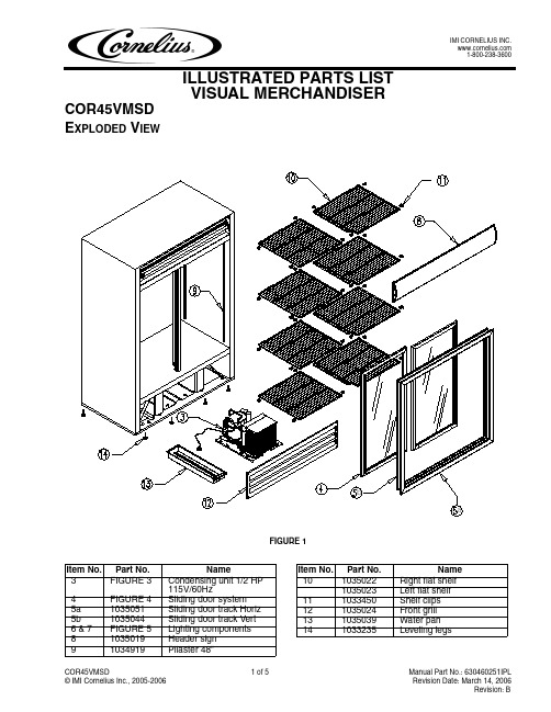
FIGURE 5
Item No.
1 2 3 4 5
Part No.
1034893 1034936 1033256 1033257 1035400
Name
Ballast QT2x32 T8/120 Lamp Lampholder Lampholder cap Fluorescent tube T8 FO32/865/XP/ECO
B A
FIGURE 4
Item No.
A B 1 2 3 4
Part No.
1042081 1035018 1035053 1035047 1035048 1035009
Name
Complete sliding door Left Complete sliding door Right Sliding door rail* Sliding door seal Sliding door gasket Glass pane
7 8 9
Part No.
1035042 1034855 1033247
Name
Fan motor bracket Fan motor and blade Fan guard
Manual Part No.: 630460251IPL Revision Date: March 14, 2006 Revision: B
Item No.
1 2 3 4 5
Part No.
1034923 1034924 1035392 1034925 1037654
Name
Evaporator Accumulator Heat exchanger Thermostat Thermostat bracket
FIGURE 2
模块化生产系统中的搬运分拣站设计说明书

模块化并不是一个新的概念,早在20世纪初期其就被引入了机械制造业。人们将模块与物理产品联系到了一起,明确了模块的功能和特征。模块化生产技术的基本方法是将产品的制造问题通过产品重组和过程重组转化为或部分转化为批量制造问题,即提供给用户的是全新的、定制的个性化产品,而实际产品则主要由标准的模块组成。模块化生产系统由于其建立方便、模块的适应范围广、可重构性强等特点,在国内外得到了广泛的运用。
Keywords:Modular,Programmable controller,The configuration
第1章 绪 论
1.1 概述
随着现代化工业生产的发展,气动技术、液压技术、传感器技术、PLC技术、网络及通讯技术等技术的紧密结合而形成的机电液、机电气、机电光一体化的自动化控制技术在工业生产中正起着越来越重要的作用,自动化生产系统已成为当今工业生产的重要组成部分。模块化生产系统就是一个工业自动化生产系统,是基于机电气(液)一体化技术、PLC控制与机器人结合的全自动加工装配系统。
模块化搬运分拣站是模块化生产系统(MPS)的一部分。它既可以作为一个独立的部分单独使用,同时也可以与供料站、检测站、加工站、安装站、存储站等组合成一个整体的自动化生产系统。本文介绍基于模块化的搬运分拣站的工作原理、PLC程序设计与控制、以及组态程序的设计等内容,重点是关于模块化搬运分拣站的PLC控制程序的设计以及与组态程序的配合调试。
模块是构成产品的一部分,具有独立功能,具有一致的几何连接接口和一致的输入、输出接口的单元,相同种类的模块在产品族中可以重用和互换,相关模块的排列组合就可以形成最终的产品。模块化的产品设计可以达到以下几个目的:模块的组合配置,可以创建不同需求的产品,满足客户的定制需求 ;相似性的重用,既可以重用已有零部件和已有设计经验,也可以重用整个产品生命周期中的采购、物流、制造和服务资源;减少产品工程复杂程度,因为模块是产品部分功能的封装,产品设计人员使用具体模块时根本不用关心内部实现,可以使研发人员更加关注顶层逻辑,提高产品工程管理质量和产品的可靠性。产品平台就是描述产品系列的模块化结构及模块的功能、模块间的几何连接接口和输入输出接口。产品平台是不同目标市场需求的抽象表达,是企业划分模块的基础,产品平台和模块是相辅相成、相互依存的。因此,从以上论述和观点来看,产品的平台化、模块化是连接产品研发和大规模定制生产的桥梁。模块化产品是达到大规模定制和不断的持续改进企业商业能力的首要前提。
Kalmar 货物搬运机产品参数表说明书

1 000 – 1 500KGS1.0C, S1.2C, S1.5C COUNTERBALANCED STACKER1.1 Manufacturer (abbreviation) 1.2 Manufacturer’s type designation1.3 Drive: electric (battery or mains), diesel, petrol, fuel gas 1.4 Operator type: hand, pedestrian, standing, seated, order-picker 1.5 Rated capacity/Rated load Q (t)1.6 Load centre distancec (mm)1.8 Load distance, centre of drive axle to fork x (mm)1.9 Wheelbasey (mm)2.1 Service weight U kg 2.2 Axle loading, laden front/rear kg 2.3 Axle loading, unladen front/rearkg3.1 Tyres: polyurethane, topthane, vulkollan, front/rear 3.2 Tyre size, front ø (mm x mm)3.3 Tyre size, rearø (mm x mm)3.5 Wheels, number front/rear (x = driven wheels) 3.7 Tread, rearb 11 (mm)5.1 Travel speed, laden/unladen km/h 5.2 Lift speed, laden/unladen m/s 5.3 Lowering speed, laden/unladen m/s 5.8 Max. gradeability, laden/unladen %5.10 Service brake6.1Drive motor, S2 60 minute ratingkW 6.2 Lifting motor, S3 15% rating J kW6.3 Battery according to DIN 43531/35/36 A,B,C, no 6.4 Battery voltage/nominal capacity K5 (V)/(Ah)6.5 Battery weight U kg 6.6Energy consumption according to VDI cyclekWh/h at number of cycles8.1 Type of drive unit 10.7 Sound pressure level at the driver’s seat dB (A)4.1 Tilting mast forwards/backwards tilta /b (°)4.2 Height of mast, lowered Ò h 1 (mm)4.4 Lifth 3 (mm)4.5 Height of mast, extended m h 4 (mm)4.7 Over head guard height h 6 (mm)4.9 Height drawbar in driving position min./max. Þ h 14 (mm)4.15 Height, lowered h 13 (mm)4.19 Overall length l 1 (mm)4.20 Length to face of forks l 2 (mm)4.21 Overall widthb 1/b 2 (mm)4.22 Fork dimensions DIN ISO 2331 « s/e/l (mm)4.23 Fork carriage DIN 15173, Class/form A,B4.24 Fork carriage width b 3 (mm)4.25 Distance between fork-armsb 5 (mm)4.31 Ground clearance under mast, with load m 1 (mm)4.32 Ground clearance, centre of wheelbase m 2 (mm)4.33Load dimension b 12 × l 6 crosswaysb 12 × l 6 (mm)4.34.1 Aisle width for pallets 1000mm x 1200mm crossways A st (mm)4.34.2 Aisle width for pallets 800mm x 1200mm lengthwise A st (mm)4.35 Turning radiusW a (mm) S1.0C S1.2C Battery Battery Pedestrian Pedestrian1.0 1.2 500 500 211 211 13001450Vulkollan Vulkollan Vulkollan Vulkollan254 x 125 254 x 125200 x 100200 x 1001x 2 1x 2837 837HYSTER HYSTER2180 z 2280 520 2660 545 29351175100512909904 4 3 3 no no24V300Ah z24V400Ah233 303 1.46 1.884.85.0 4.8 5.0 0.26 0.28 0.20 0.28 0.34 0.20 0.34 0.20 11.0 11.0 10.0 10.0ElectricElectromagneticElectricElectromagneticAC-Controller AC-Controller< 70 < 70+ 2- 4+ 2- 42325 2325 3372 3372 3961 3961 231223121180 1485 1180 1485 35 35 2742 2892 1742 1892788 939 788 93935 100 1000 35100 10002A2A700 700240 672 240 672 59 59 76 76800 x 1200800 x 12003111 3258 3227337415601707D I S T I N G U I S H I N G M A R K SW E I G H T ST Y R E S / C H A S S I SD I ME N S I O N SP E R F O R M A N C E D A T AE L E C T R I C E N G I N ED R I VE /L IF TM E C H A N I S MA D D I T I O N A L D A T ASpecification data is based on VDI 21981.1S1.5C S1.0C S1.2C 1.2 Battery Battery Battery 1.3PedestrianStand onStand on1.41.5 1.0 1.2 1.5500 500 500 1.6211 211 211 1.7 1600 1300 1450 1.8HYSTER HYSTER HYSTER 2360 2210 z2310 2.13345 515 530 2680 555 2955 2.2 1420 940 1195 1015 1315 995 2.3 Vulkollan Vulkollan Vulkollan VulkollanVulkollan Vulkollan 3.1254 x 125 254 x 125 254 x 125 3.2200 x 100200 x 100200 x 1003.3 1x 2 1x 2 1x 2 3.5 837 837 837 3.74.85.0 5.56.0 5.5 6.0 5.10.180.280.260.280.200.285.20.34 0.20 0.34 0.20 0.34 0.20 5.3 9.0 9.0 11.0 11.0 10.0 10.0 5.8ElectricElectromagneticElectricElectromagneticElectricElectromagnetic 5.104 4 4 6.13 3 3 6.2 no no no 6.324V400Ah24V 300Ah z 24V 400Ah 6.4 303 233 303 6.5 2.292.613.256.6AC-Controller AC-Controller AC-Controller 8.1< 70 < 70 < 70 10.7+ 2- 4+ 2- 4+ 2- 44.1 2325 2325 2325 4.2 3372 3372 3372 4.4 3961 3961 3961 4.523122312 23124.71180 1485 1220 1525 1220 1525 4.9 35 35 35 4.15 3042 2742 2892 4.1920421742 1892 4.20788 939 788 939 788 939 4.2135 100 100035100 100035100 1000 4.222A2A2A4.23 700 700 7004.24240 672 240 672 240 672 4.25 59 59 59 4.31 76 76 76 4.32800 x 1200800 x 1200800 x 12004.33 3406 3111 3258 4.34.1 3522 3227 3374 4.34.21855156017074.35DISTINGUISHING MARKSWEIGHTS TYRES / CHASSISDIMENSIONSPERFORMANCE DATAELECTRIC ENGINEDRIVE/LIFT MECHANISM ADDITIONAL DATAFORKS:S1.0C: 35 x 100 x 1 000 mm long. S1.2C: 35 x 100 x 1 000 mm long. S1.5C: 35 x 100 x 1 000 mm long.Fork spacing: Inside to inside: 240 mm. Outside to outside: 672 mm.MAST INFORMATIONS1.0C-S1.2C-S1.5CValues shown are for standard equipment. When using non-standard equipment these values may change. Please contact your Hyster dealer for information.NOTE : T he rated capacities shown are for masts in a vertical position on trucks equipped with standard or sideshift carriage, and nominal length forks. Masts above themaximum fork heights shown in the mast table are classified as high lift, and depending on the tyre/tread configuration may require reduced capacity, restricted back tilt or wide tread.Lift height h 3 mmLift heighth 3 mmHeight, mast lowered Òh 1 mmFree lift h 2 mmHeight, mast extended rh 4 mmHeight, mast lowered h 1 mm Height, overhead guardh 6 mmHeight, mast extended Òh 4 mmHeight, overheadguard h 6 mm2 Stage LFL3 Stage FFL2572 1925 3161 - 2972 2125 3561 2262 3372 2325 3961 2312 3672 2475 4261 2412 4072 2675 4661 26123876 1305 1875 4451 - 4176 1405 1975 4751 - 4626 1555 2125 5201 23125076 1705 2275 5651 2312DEPENDABILITYn Tough counterbalance performance.n Comprehensive selection of mast configurations.n S pecific options available to ensure trucks meet exact operation requirements, e.g. load back rest, FEM forks and carriages.n C ANbus electronics reduce wiring complexity, for increased reliability.n I ntegral sideshift allows optimum fork positioning for all applications.PRODUCTIVITYn O perator-friendly tiller head controls for improved load handling.n P ower steering available for both pedestrian and stand-on operation.n C ompact chassis design improves handling in confined spaces.n A utomatic braking on release of themovement controls.n Regenerative braking and anti-roll back as standard.n A djustable performance settings to suit specific operating conditions.ERGONOMICSn T iller head ergonomically designed for maximum operator comfort.n C ontrols positioned to allow operation witheither hand.n E PAS (Electronic Power Assistance Steering) system provides optimum directional control at any speed.n Software speed reduction on cornering.n On/off auxiliary functions for tilt and side shift.n V ertically mounted lifting motor with dampers to reduce noise and vibration.COST OF OWNERSHIPn P owerful AC traction motor provides superior performance and increased load moves per hour.n Increased load moves per hour reduces operating costs. n T raction and hydraulics managed through MOSFET high frequency Combi controller.n I ntelligent management system optimisesenergy usage.n Key-pad access allows greater management control.SERVICEABILITYn D iagnostic indicators for early warning ofmaintenance requirements.n B uilt in diagnostic system allows preventivemaintenance communications, increasing uptime.n U pdated components permit extendedservice intervals.n D river Diagnostic Interface (DDI) informs operator in real-time about truck conditions.n H our meter and battery discharge indicator with lift interrupt fitted as standard.PRODUCT FEATURESwww.hyster.eu*********************/HysterEurope@HysterEurope/HysterEuropeSTRONG PARTNERS. TOUGH TRUCKS.TMFOR DEMANDING OPERATIONS, EVERYWHERE.Hyster supplies a complete range of warehouse equipment,IC and electric counterbalanced trucks, container handlers and reach stackers. Hyster is committed to being much more than a lift truck supplier.Our aim is to offer a complete partnership capable ofresponding to the full spectrum of material handling issues: Whether you need professional consultancy on your fleet management, fully qualified service support, or reliable parts supply, you can depend on Hyster.Our network of highly trained dealers provides expert,responsive local support. They can offer cost-effective finance packages and introduce effectively managed maintenance programmes to ensure that you get the best possible value. Our business is dealing with your material handling needs so you can focus on the success of your business today and in the future.HYSTER EUROPECentennial House, Frimley Business Park, Frimley, Surrey, GU16 7SG, England.Tel: +44 (0) 1276 538500Printed in The Netherlands. Part number: 3990201 Rev. 06-12/16-TLCHYSTER-YALE UK LIMITED trading as Hyster Europe. Registered Address: Centennial House, Building 4.5, Frimley Business Park, Frimley, Surrey GU16 7SG, United Kingdom.Registered in England and Wales. Company Registration Number: 02636775. HYSTER,and FORTENS are registered trademarks in the European Union and certain other jurisdictions.MONOTROL ® is a registered trademark, and DURAMATCH and are trademarks in the United States and in certain other jurisdictions.。
新型、迷你型、耐用的障碍物搬运机说明书

Barrier Lifting Grab (BLG-1)
PRODUCT FEATURES AND BENEFITS:
• New, compact & rugged design holds up to the work environment where barriers are used.
•. Replaceable polyurethane pads protect barrier.
•. Alloy steel dog-point pads bite into painted barrier surfaces (typical in coastal areas).
•. Centering guide cut out on grab shoe helps to properly center tong over barrier for a level lift.
Lower crane, line must go slack to engage Auto-Latch, lift tong off barrier and
Rated Cap. (Lbs.)
Part No.
Wt. (Lbs.)
With Polyurethane Lifting Pads
8,500
BLG-4
602
14,500
BLG-7
652
With Steel "Dog Point" Lifting Pads
8,500
BLG-4-DP
• Lifting eye allows for easy hook attachment, self-centers rigging, and will accommodate a fork.
课程设计块状物品推送

前言在自动包裹机的包装作业中,经常需要将物品从前一个工序推送到下一个工序,块状物品推送机已经广泛运用到了物品包装工序以及各种其它机构中,并发挥着不可替代的作用。
下图为块状物品自动包装机TDB---450型,此机构即用到了块状物品推送机构。
目录1.设计题目. . . . . . . . . . . . . . . . . . . . . . . . . . . . . . . . .. . 32.设计数据和要求. . . . . . . . . . . . . . . . . . . . . . . . . . . . . . . . 32.1设计数据2.2设计要求3.机械运动方案设计及最终方案构件尺寸. . . . . . . . . . . . . . . . 33.1方案设计13.2方案设计23.3方案设计33.4最终确定方案的构件尺寸4.机械运动和动力设计. . . . . . . . . . . . . . . . . . . . . .. . . . . 74.1推杆运动规律分析4.2电动机的功率及满载转速分析4.3飞轮的转动惯量分析5.所选方案的机构运动学分析. . . . . . . . . . . . . . . ….. ... . . 95.1推杆位移变化曲线5.2推杆速度变化曲线5.3推杆加速度变化曲线6.所选方案的运动循环图. . . . . . . . . . . . . . . ... . …. ..… .. . 117.小组总结. . . . . . . . . . . . . . .. . . . . . . . . . . . ….. .. …... . 118.参考资料. . . . . . . . . . . . . . . . . . . . ……. . . . . . . . . .. 12一.设计题目:块状物品推送机的机构综合与机构设计二.设计数据和要求:1. 推送的距离H=120mm,生产率为每分钟推送物品120件。
产品搬运作业工业机器人说明书 (2)

机械专业综合课程设计说明书产品搬运作业工业机器人学院(系):机电工程学院专业:机械设计制造及其制动化学生姓名:学号:指导教师:完成日期:2016年12月27日目录1 绪论 (1)1.1 设计背景 (1)1.2 工业机器人发展现状 (1)2 Robotstudio机器人 (2)2.1机器人的选用 (2)2.2 IRB 120机器人的载荷 (1)3程序数据创建与I/O信号配置 (1)3.1工具数据创建 (1)3.2工件坐标数据创建 (2)4机器人的程序 (4)4.1程序的编写与注解 (4)4.2程序修改 (10)5示教目标点与仿真 (10)5.1三个目标点的示教 (10)5.2机器人仿真 (13)6 Robotstudio共享打包与解包 (13)6.1工作站共享功能 (13)6.2工作站打包 (14)1 绪论1.1 设计背景科技的进步与革新推动着生产力的不断发展,促使生产关系产生变革。
自工业革命以来,人力劳动已经逐渐被机械所取代,而这种变革为人类社会创造出巨大的财富,极大地推动了人类社会的进步。
如今,机电体化、机械智能化等技术应运而生。
工业机器人的出现是人类在利用机械进行社会生产史上的一个里程碑。
在发达国家,工业机器人的自动化生产线成套设备己成为现代加工制造业的主流。
汽车行业、电子电器行业、工程机械等行业正以极快的速度大量使用工业机器人。
多功能机器人实训台,包括ABBIRB120型机器人,三菱FX3U-48MR型PLC,模式选择控制面板模块,送料模块,模拟压铸模块,输送带模块,物料检测模块,搬运、码垛模块和几何轨迹模块等。
现代计算机软硬件技术、计算机图形技术高速发展,以及数字仿真技术的广泛应用,为工业机器人离线编程技术的实际应用提供了有利条件。
同时,现代生产的高效率、柔性化需求也促使了工业机器人离线编程软件产品的产生。
机器人离线编程系统,是利用计算机图形学技术,建立起机器人及其工作环境的模型,利用机器人语言及相关算法,通过对图形的控制和操作在离线的情况下进行轨迹规划。
SPT120推料装置设计
优秀设计本科生毕业设计说明书(毕业论文)题目:学生姓名:学号:专业:摘要板材送料装置广泛应用在大型板材加工中,是板材加工设备的重要组成部分。
本产品本着结构简单,能耗低,对板材磨损小的原则所设计,目的是为了提高板材加工设备的生产效率。
该机通过对推块的设计,解决了能耗低,结构简单,对板材磨损小的等问题。
通过感应装置和控制中心控制电机和传动部件的运动,将本设备的能耗降到最低限度。
为了减少在板材运送时设备与板材之间的摩擦,采用了辊传动,使设备与板材之间的摩擦方式变为滚动摩擦,最大限度的减小了设备工作中对板材的磨损。
关键词:轴推块支撑柱电机AbstractThe plate feeding equipment widespread application in the large-scale plate processing, is the plate processing equipment important constituent. This product is simple in line with the structure, the energy consumption is low, wears the small principle to the plate to design, the goal is in order to enhance the plate processing equipment the production efficiency.This machine through pushes the block the design, solved the energy consumption to be low, the structure was simple, wore slightly to the plate and so on the questions. Through the induction installment and the control center control electrical machinery and the transmission part movement, falls this equipment energy consumption the threshold.In order to reduce ships when the plate between the equipment and the plate friction, has used the roller transmission, causes between the equipment and the plate friction way becomes the rolling friction, maximum limit reduced in the equipment work to the plate attrition. Key word: Axis Pushes the block Prop Electrical machinery目录摘要 (Ⅰ)Abstract (Ⅱ)第 1 章概述 (1)1.1 SPT120-12A.5.1 推料装置 (1)1.2 送料装置的作用和要求 (1)1.3 送料装置的分类和特点 (2)1.4 国内外研究状况 (2)1.5送料装置课题研究意义 (2)1.6课题来源 (3)1.6课题目的 (3)第 2 章送料装置各部零件的设计 (4)2.1 SPT120-12A.5.1推料装置简介 (4)2.2 SPT120-12A.5.1 推料装置的工作原理用 (4)2.3 SPT120-12A·5·1推料装置结构组成及其各部分功用 (5)2.3.1动力源 (5)2.3.2传动件 (5)2.3.3支撑柱 (6)2.3.4推块 (6)2.4推料装置的技术特点 (7)2.5设计的有关技术参数 (7)第 3 章推料装置的工艺规程设计 (8)3.1 轴的功用 (8)3.2 工艺规程设计 (8)3.3.1确定毛坯的制造形式 (8)3.3.1轴的工艺方案 (8)第 4 章轴的校核 (10)4.1按扭转强度条件计算 (10)4.2确定轴的主要结构尺寸 (11)4.3连传动的受力分析 (11)4.4按弯扭合成强度条件计算 (13)4.5按疲劳强度条件进行精确校核 (16)第 5 章经济分析与资源分析 (20)结论 (22)致谢 (23)参考文献 (24)专题论文 (25)附录外文翻译 (42)第一章概述1.1SPT120-12A·5·1 送料装置SPT120-12A·5·1 推料装置推料装置主要应用大型板材加工设备中,通过自动快速的运送板材提高了板材加工设备的工作效率。
送料机说明书
1.3 课题的国外发展状况
经过 50 多年的发展,国外包装机械工业已经形成了独立完整的体系,成为 机械制造的一个重要分支。首先,国外包装机械产量稳定增长。由于消费结构 和销售形式的变化,加之国际贸易的发展,对包装机械的需求日益增加,因此 国外包装机械的产量逐年增长;其次包装机械产品门类齐全,品种繁多。包装 机械的品种不断增加,据统计国外包装机械品种已达 140 余种,并已形成系列 产品,近年还出现了一大批高度技术密集型的包装生产线;最后,包装机械生 产自成体系,并向专业化生产方向发展。国外包装机械工业的发展趋势是: (1) 重点发展食品包装机械; (2) 在系统优化设计的基础上,包装单机向高速化方向发展; (3) 在包装机上广泛应用电子计算机; (4) 一方面为满足现代商品包装多样化的需求,发展适应多品种、小批量的通
2.2 送料机的特点及应用 ............................................... 7
2.3 设计要求及选择方案 ............................................... 9 斗式提升机的设计 ........................................... 11
4
1.2 课题的国内发展状况
包装机械工业已经成为我国国民经济中不可缺少的非常重要的新兴行业。 我 国目前从事包装机械生产的企业约有 1500 多家, 其中具有一定规模的企业近 400 家,产品有 40 类,2700 多种,资料出处其中有一批既能满足国内市场需要,又 能参与国际市场竞争的优质产品。我国包装机械工业历史短,总体技术水平和生 产能力较低, 但近年来在国内巨大包装市场的促进下, 并受国外先进技术的影响, 发展速度很快,局部技术水平有了明显提高。根据我国国情,包装机械工业发展 的趋势是: (1) 引进、消化、吸收国外先进技术,建立一批包装机械骨干企业,包括 个别中外合资企业,从而可满足大型包装生产线以及高精度、高自动 化程度的单机或机组生产的需要, 进而可加快包装机械国产化的速度; (2) 大多数企业要重点发展中、小型包装机械。我国大多数企业技术水平 不高,生产能力较低,生产以单机为主的中、小型包装机械比较适宜, 但要在此基础上不断提高制造精度、自动化程度和配套能力; (3) 在包装机械生产中,大量引入高新技术,研制组合式、模块式等先进 结构,使包装机械产品设计先进、使用可靠,使其性能指标、工艺水 平、 “三化”水平高,向机电结合、主辅机结合、成套联线方向发展; (4) 以满足重点商品的包装为出发点,发展包装机械新品种。重点开发的 包装机械设备及其研究方向为:灌装设备、贴标设备、袋成型-充填 -封口机、折叠式裹包设备、真空换气包装设备、热缩包装机和拉伸 包装设备、无菌包装设备。
- 1、下载文档前请自行甄别文档内容的完整性,平台不提供额外的编辑、内容补充、找答案等附加服务。
- 2、"仅部分预览"的文档,不可在线预览部分如存在完整性等问题,可反馈申请退款(可完整预览的文档不适用该条件!)。
- 3、如文档侵犯您的权益,请联系客服反馈,我们会尽快为您处理(人工客服工作时间:9:00-18:30)。
机械原理课程设计题目:块状物品推送机班级:2012级机械设计制造及其自动化2班组员:胡鑫亮(组长) 刘润华张鹏飞郭日哲李东杰黄玉指导教师:康辉梅工程与设计学院2014年6月12日目录分工明细 (3)一.设计任务书 (4)1.设计题目 (4)2. 设计条件及要求 (4)3. 设计任务 (4)二.方案选择 (5)方案一 (5)方案二 (6)方案三 (6)三.基本参数 (7)1.凸轮设计 (7)2.带传动 (8)3.蜗轮蜗杆 (9)4.减速系统设计 (9)5.电动机性能要求 (10)6.电动机的功率及满载转速分析 (10)四.滚子从动件各个阶段相关方程 (10)位移速度及加速度变化曲线 (12)编程结果 (15)三维模型 (18)五.心得体会 (20)六.参考文献 (21)分工明细:组长:胡鑫亮方案设计:胡鑫亮,张鹏飞,刘润华,郭日哲,李东杰,黄玉数据计算:胡鑫亮,张鹏飞,刘润华,郭日哲,李东杰,黄玉三维模型制作:张鹏飞,刘润华,胡鑫亮仿真分析:胡鑫亮设计说明书:郭日哲PPT制作:黄玉数据核对:郭日哲,李东杰,黄玉一.设计任务书1.设计题目:块状物品推送机2.设计条件及要求:1.向上推送距离:120mm。
生产率:120件/min2.原动机为同步转速为3000r/min的三相交流电动机。
通过减速装置带动执行机构主动件等速转动。
3.由物品处于最低位置时开始,当执行机构主动件转过150°时,推杆从最低位置运动到最高位置;当主动件在转过120°时,推杆从最高位置又回到最低位置;最后当主动件再转过90°时,推杆在最低位置停留不动。
4.设推杆上升过程中所受的物品重力和摩擦力为常数,其值为500N;设推杆下降过程中所受摩擦力为常数,其值为100N。
5. 在满足行程的条件下,要求推送机的效率高(推程最大压力角小于35°),结构紧凑,振动噪声小。
3.设计任务1.至少提出三种运动方案,然后进行方案分析评比,选出一种运动方案进行机构综合;2.确定电动机的功率与满载转速;3.设计传动系统中各机构的运动尺寸,绘制推送机的机构运动简图;4.在假设电动机等速运动的条件下,绘制推杆在一个运动周期中位移、速度和加速度变化曲线;5.编写课程设计说明书。
二.方案选择方案一凸轮-连杆组合机构:实现行程放大功能,在水平面得推送任务中,优势较明显,但在垂直面中就会与机架产生摩擦,加上凸轮与摆杆和摆杆与齿条的摩擦,积累起来摩擦会很大造成效率较低。
方案二凸轮机构:凸轮以等角速度回转,它的轮廓驱使从动件,可使推杆实现任意的运动规律,机构磨损较为严重,稳定性能差且效率不高,不能满足设计要求。
方案三蜗轮蜗杆-凸轮:运用蜗轮蜗杆传递动力,采用了带传动,利用凸轮机构回转运动,使得效率较高并且运动精确稳定效应迅速,可使推杆有确定的运动。
三.基本参数1.凸轮设计偏心距e=0,基圆半径r0=140mm。
根据机械原理书上用解析法设计凸轮轮廓线的实质是建立凸轮轮廓线的数学方程式。
已知偏距e,基圆半径r,从动件的运动规律s=s(δ),则理论凸轮轮廓曲线方程:x理论=(s+s0)sinδ+e sinδ,y=(s+s0)cosδ-e cosδ。
(s0=√r02−r2)而实际凸轮的曲线方程:x p=x+r r dy/√dx2+dy2y p=y+r r dx/√dx2+dy2以此作为程序编制基础算法,然后明确程序编制需要哪些变量,利用MATLAB中相关函数进行计算,求出需要设计的理论,实际凸轮的轮廓曲线,并且利用PLOT函数进行画图,把从动件加速度,速度,位移进行画出来,并生成一个小型的动画,进行凸轮与滚子推杆从动件之间运动规律的仿真设计。
2.带传动平带轮技术参数(1)选定带型和基准直径设计功率Pd(KW): 5带型:胶帆布平带工况系数: 1.0小带轮基准直径dd1(mm): 140大带轮基准直径dd2(mm): 280(2)轴间距的确定初定轴间距a0(mm): 1000所需带长Ld(mm): 2664.63实际轴间距a:(mm): 1000(3)带速、包角和V带根数带速v: 21.991小带轮包角α: 171.98包角修正系数Ka: 0.973.蜗轮蜗杆蜗杆传动设计报告(1)设计参数传递功率: 1传递效率: 0.938蜗杆转速n1: 1500蜗轮转速n2: 120传递转矩: 6.367传动比i: 12.5(2)蜗杆副参数端面模数mn: 2.5法向模数Mt: 2.44法向压力角αn: 20导程角γ: 12.58基圆柱导程角βb: 0.414.减速系统设计采用皮带加齿轮的减速装置。
一级降速将原速用皮带减速,减为1500r/min。
二级用齿轮减为120r/min。
优点:传动机构简单、成本低廉;具有良好的挠性,可缓和冲击,吸收振动;过载时带与带轮间会出现打滑,可防止损坏其他零件。
5.电动机的性能要求推送机的原动件为同步转速为3000r/min的三相交流电动机,通过减速装置带动执行机构主动件等速转动。
电机与减速器的连接采用平带连接。
然后再用齿轮减速6. 电动机的功率及满载转速分析电动机效率η1=73% 单头蜗杆传动效率η2=75% V带传送效率η3=96% 凸轮传动效率η4=93% 移动副传动效率η5=85%在一个周期T=0.5s 阻力功w=(500*120+100*120)*0.001=72J 阻力功率p1=w/T=144J/s机构总效率η=η1*η2*η3*η4*η5=0.415机构驱动力功率p2=p1/η=0.3764 J/s=1.289kw电机功率应确定为1.8kw;四.滚子从动件各个阶段相关方程滚子从动件各个阶段相关方程推程等加速段:0≤φ≤Φ2既0°-75°根据:S=2hΦ2φ2 ,v=4hωΦ2φ,a=4hφ2Φ2。
S=2x2/1875,v=4x/1875,a=4/1875。
推程等减速:Φ2≤φ≤Φ,即 75°-150°根据:s=h-2hΦ2(Φ−φ)2,v=4hωΦ(Φ-φ),a=−4hω2Φs=120-(150-x)2/1875, v=4hΦ2(Φ-φ),a=-4/1875当处于远休止:既h=120,v=0,a=0.回程简谐运动:Φ+Φs≤φ≤Φ+Φs+Φ‘,即160≤φ≤250S=h2[1+cosπΦ′(φ-Φ-Φs)],V=−hπω2ΦsinπΦ′(φ-Φ-Φs),a=−hπ2ω22Φ′2cosπΦ′(φ-Φ-Φs)处于近休止:Φ+Φs+Φs′≤φ≤2π,即250≤φ≤360s=0,v=0,a=0盘型凸轮理论与实际轮廓方程盘型凸轮理论方程:盘型凸轮实际方程:x理论=(s+s0)sinδ+e sinδ,y=(s+s0)cosδ-e cosδ,(s0=√r02−e2)x p=x+r r dy/√dx2+dy2 , y p=y+r r dx/√dx2+dy2电动机等速运动的条件下,绘制推杆在一个运动周期中位移、速度和加速度变化曲线:坍腔地段安全质量保证措施编程结果:>> clear;r0=140;rr=20;h=150;e=0;delta01=150;delta02=0;delta03=120;hd=pi/180;du=180/pi;se=sqrt(r0*r0-e*e);n1=delta01+delta02;n3=delta01+delta02+delta03;n=360;tan1=0:pi/75:delta01/2;s1=2*h*tan1.^2/delta01^2;v1=4*h*tan1*hd/(delta01*hd)^2;a1=4/1875;tan2=delta01/2:pi/75:delta01;s2=h-2*h*(delta01-tan2).^2/delta01^2;v2=4*h*(delta01-tan2)*hd/(delta01*hd)^2;a2=-44236.8;tan3=delta01:pi/75:n1;s3=h;v3=0;a3=0;tan4=n1:pi/75:n3;k=tan4-n1;s4=0.5*h*(1+cos(pi*k/delta03));v4=-0.5*pi*h*sin(pi*k/delta03)/(delta03*hd)^2;a4=0.5*pi*pi*h*cos(pi*k/delta03)/(delta03*hd)^2;tan5=n3:pi/75:n;s5=0;v5=0;a5=0;figure(1);hold on;grid on;title('凸轮从动件位移');xlabel('x/mm');ylabel('y/mm');plot([-(r0+h-40) (r0+h)],[0 0],'k');plot([0,0],[-(r0+h) (r0+rr)],'k');plot(tan1,s1,'r',tan2,s2,'r',tan3,s3,'r',tan4,s4,'r',tan5,s5,'r'); figure(2);title('凸轮从动件速度');hold on;grid on;xlabel('x/mm');ylabel('y/mm');plot([-(r0+h-40) (r0+h)],[0 0],'k');plot([0,0],[-(r0+h) (r0+rr)],'k');plot(tan1,v1,'r',tan2,v2,'r',tan3,v3,'r',tan4,v4,'r',tan5,v5,'r'); figure(3);title('凸轮从动件加速度');hold on;grid on;xlabel('x/mm');ylabel('y/mm');plot(tan1,a1,'r',tan2,a2,'r',tan3,a3,'r',tan4,a4,'r',tan5,a5,'r');xlabel('x/mm');ylabel('y/mm');plot(tan1,a1,'r',tan2,a2,'r',tan3,a3,'r',tan5,a5,'r');三维模型:五.心得体会经过两周的奋战我们的课程设计终于完成了,在这次课程设计中我学到得不仅是专业的知识,还有的是如何进行团队的合作,因为任何一个作品都不可能由单独某一个人来完成,它必然是团队成员的细致分工完成某一小部分,然后在将所有的部分紧密的结合起来,并认真调试它们之间的运动关系之后形成一个完美的作品。
