LU-M100单色液晶显示控制木芯检测仪说明书
室内环境监测传感器 AM100 系列用户手册说明书

室内环境监测传感器AM100系列用户手册安全须知为保护产品并确保安全操作,请遵守本使用手册。
如果产品使用不当或者不按手册要求使用,本公司概不负责。
严禁拆卸和改装本产品。
请勿将产品放置在不符合工作温度、湿度等条件的环境中使用,远离冷源、热源和明火。
本产品作为室内环境监测使用,不可作为计量工具使用。
如长期未使用本产品,请将电池取下。
否则可能造成电池泄漏并损坏内部元件。
请勿使产品受到外部撞击或震动。
清洁产品时请避免产品进水以及使用各种清洁剂或溶剂,如苯和酒精。
表面清洁可用湿润的软布擦拭,再用干燥的软布擦干。
为了您的设备安全,请及时修改设备默认密码(123456)。
产品符合性声明AM100系列符合CE,FCC和RoHS的基本要求和其他相关规定。
版权所有©2011-2022星纵物联保留所有权利。
如需帮助,请联系星纵物联技术支持:邮箱:*********************电话:************传真:************总部地址:厦门市集美区软件园三期C09栋深圳:深圳市南山区高新南一道TCL大厦A709日期版本描述2020.06.16V1.0第一版2020.08.07V1.1新增电子墨水屏多种显示模式和配置示例,App界面更新OC、CO2屏幕告警阈值可设置2.ToolBox软件中文图片替换2020.09.25V2.0版式替换2021.03.02V2.1更新版式,型号AM100/AM102变更为AM104/AM107 2021.12.30V2.2更新品牌Logo目录一、产品简介 (5)1.1产品介绍 (5)1.2产品亮点 (5)二、产品结构介绍 (5)2.1包装清单 (5)2.2外观概览 (6)2.3产品尺寸(mm) (6)2.4电子墨水屏 (7)2.4.1显示说明 (7)2.4.2屏幕模式切换 (8)2.5电源按钮 (9)三、电池安装 (9)四、产品配置 (9)4.1配置方式 (10)4.1.1NFC配置 (10)4.1.2USB配置 (11)4.2LoRaWAN基本配置 (12)4.3时间同步 (14)4.4基本设置 (15)4.5高级设置 (16)4.5.1数据采集设置 (16)4.5.2校准设置 (16)4.5.3告警设置 (17)4.6维护 (17)4.6.1升级 (17)4.6.2备份 (18)4.6.3重置 (19)五、产品安装 (20)5.1安装注意事项 (20)5.2安装方法 (20)六、数据通信协议 (21)七、星纵云管理 (22)7.1添加星纵网关 (22)7.2添加AM104/AM107到星纵云 (24)附录 (25)二氧化碳浓度参考 (25)一、产品简介1.1产品介绍AM100系列室内环境监测器由星纵物联自主研发和设计,内置温度、湿度、光照、红外探测、TVOC、CO 2、大气压等多种传感器,帮助我们持续监测办公室、卧室、博物馆等空间的环境变化,及时调整,改善舒适度。
木材湿度测试仪

木材湿度测试仪使用说明书DT-129目录标题页数外观 (3)使用说明 (4)1. 测量指示 (4)2. 不带温度探头时仪表的测量 (5)3. (ATC)自动校正温度 (5)4. 设置自动关机时间 (6)5. 校准检测 (7)6. 保管与保养 (7)木材刻度表 (8)木材普通名称参考BS888&589:1973 (8)注意事项 (20)使用说明此款仪表是专业测量木材的湿度计。
该仪表有八个校准刻度,能准确测量达150种木材种类。
湿度计既可用完整的针形探针,也可用耐用的湿度探针测量. 使用温度探针时,能根据相关温度自动校准湿度测量. 按下“”键即刻打开仪表,按下“”键3秒可关闭仪表。
该表可在5分钟之后自动关闭,默认关机时间可设置为1~ 9分钟(看第4部分).技术指标:湿度测量量程: 6%~100%湿度分辨率: 0.1湿度测量精度: ±1%( 6%~40%)温度测量量程: -35°C~80°C温度分辨率: 1 (<=-10°C) 0.1(>-10°C)温度测量精度: ±2°C整机电流: <8mA关机电流: <3uA低电显示: <2V时显示低电符号1.测量指示打开盖子暴露针形探针或连接在仪表右边耐用的湿度探针,按下“”键打开仪表。
参考附录上的木材刻度表,并按“”键来选择正确的木材刻度(A, B, C, E, F, G, H or J)以对应与不同的木材种类。
把针形探针或耐用的湿度探针插入木材,读取测量值。
2.不带温度探头时仪表的测量校准木材的温度环境是20°C (68°F).一般来说, 温度高于20°C,测量值就会越大,低于20°C测量值就会越小.粗约的手动校正0.5%湿度含量,从以上的20°C中减去5°C。
若木材温度低于20°C,手动校正0.5%湿度含量,在测量值加上5°C。
木材湿度测试仪

木材湿度测试仪使用说明书DT-129目录标题页数外观 (3)使用说明 (4)1. 测量指示 (4)2. 不带温度探头时仪表的测量 (5)3. (ATC)自动校正温度 (5)4. 设置自动关机时间 (6)5. 校准检测 (7)6. 保管与保养 (7)木材刻度表 (8)木材普通名称参考BS888&589:1973 (8)注意事项 (20)使用说明此款仪表是专业测量木材的湿度计。
该仪表有八个校准刻度,能准确测量达150种木材种类。
湿度计既可用完整的针形探针,也可用耐用的湿度探针测量. 使用温度探针时,能根据相关温度自动校准湿度测量. 按下“”键即刻打开仪表,按下“”键3秒可关闭仪表。
该表可在5分钟之后自动关闭,默认关机时间可设置为1~ 9分钟(看第4部分).技术指标:湿度测量量程: 6%~100%湿度分辨率: 0.1湿度测量精度: ±1%( 6%~40%)温度测量量程: -35°C~80°C温度分辨率: 1 (<=-10°C) 0.1(>-10°C)温度测量精度: ±2°C整机电流: <8mA关机电流: <3uA低电显示: <2V时显示低电符号1.测量指示打开盖子暴露针形探针或连接在仪表右边耐用的湿度探针,按下“”键打开仪表。
参考附录上的木材刻度表,并按“”键来选择正确的木材刻度(A, B, C, E, F, G, H or J)以对应与不同的木材种类。
把针形探针或耐用的湿度探针插入木材,读取测量值。
2.不带温度探头时仪表的测量校准木材的温度环境是20°C (68°F).一般来说, 温度高于20°C,测量值就会越大,低于20°C测量值就会越小.粗约的手动校正0.5%湿度含量,从以上的20°C中减去5°C。
若木材温度低于20°C,手动校正0.5%湿度含量,在测量值加上5°C。
光泽仪操作说明

昆山市华立美塑胶五金科技有限公司
光泽度仪测试操作说明
一、范围:
适用于公司所有喷涂、印刷产品
二、操作方法:
1.按下仪器右边的按键,液晶显示屏有读数,说明已经连通电源。
2.打开校准板盒,将仪器测量孔放在黑色石英晶体校准板上。
3.定标:调节仪器上方的标旋钮,使读数符合标定值。
4.测量:将仪器放在需测试的样品上,显示的读数即为该样品的光
泽度值。
5.关机:仪器在开机3—5分钟后无操作时会自动关闭。
三、注意事项:
1.使用中应避免强光直射,否则影响测量准确性。
2.如仪器显示欠电需立即充电。
核准:制定:。
氯气仪使用方法
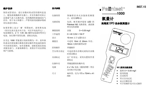
维护保养保持试管清洁,进行读数时将试管的塑料盖盖上,避免溶液溅洒在仪器上,在室外操作时防止过量湿气进入仪器内部,如用溅洒的液滴或水气存在,用干布立即擦干。
严禁用溶剂或磨砂物质对仪表进行清洁。
如果屏幕上显示’B’型图标时,请更换电池(轻压仪表后盖并向下拉,可打开电池单元)。
电池规格为:2节1.5V AA碱性电池或同等其它电池。
如长期不使用仪器,请取出电池。
百灵达1000型氯量计的质保期为一年。
意外损坏或未经授权擅自维修及错误操作所造成的损坏不在质保范围内。
如有需维修,请联系我们的技术服务部门,并索取维修号。
质保并不对法律权利产生影响。
技术参数仪器类型预编程直读式余氯浓度测量计,采用DPD法光路系统包括:配有脉冲蓝绿LED的Palintest M2光路系统、滤波器和光电传感器测量量程余氯0 – 5.00 mg/l工作温度0 – 40°C/32 – 104°F显示10 mm 文字LCD显示测量室可适用10ml或20mm外径、18mm光路的圆型试管控制操作单键操作空白/零点设定可选驻留内存模式或每次读数时重设模式内部标定出厂时设定,采用内置软件重新标定仪器外壳带键盘膜的防溅外壳电源 2 x 1.5v 电池(随机附赠)带自动关机节电功能尺寸袖珍型,仅为173 x 75/44 x 41mm1000氯量计高精度DPD法余氯测量计INST.15__________®m g/lC H LO R OM E TE RC HL OR IN EC HL OR EC HL ORK LO RC LO ROO NM2系列光路系统∙量程 0 – 5.00 mg/l∙使用简便∙自动校零∙零点自动记忆∙显示诊断信息∙可手持操作也可台式操作。
数显表使用说明.docx

!-GCS型光栅数显系统(英文米字管提示)使用说明书恒兴星精密仪器有限公司尊敬的用户:欢迎您使用深圳市恒兴星最新开发液晶英文提示的GCS 光栅数显系统,恒兴星光栅系统广泛用于铣床、磨床、镗床、线切割、车床,它的应用有助于提高生产效率、显示直观、操作方便、精度准确、重复性稳定,是模具制造业、机械加工业、精密测量仪器必不可少的装置。
本系统设置多种智能化功能,如SDM300点记忆、等分圆和椭圆、斜面加工、R的加工 8个面选择、分中功能的用法,还配置了计算器,等等功能,使用起来十分方便。
应用恒兴星的光栅数显系统,不须经过培训,按照英文使用说明书每步提示一看就懂。
最适合刚使用操作的新手,对于熟练得操作者更是得心应手。
要想了解有关的细节请详细阅读使用说明书。
安全注意事项:打开产品包装,取出箱内数显表与电子尺相接,然后插上电源检查显示是否正常。
①开箱后检查外观是否完好,若有故障应立即联系本公司销售部,切勿自行拆卸维修。
②本装置使用110V~220V, 50Hz~60Hz 的交流电源,电源插头是带有接地脚的三芯电源插头。
三芯电源插座地线一定要接地牢靠。
③用户不可以自行打开机壳修理,表内有很高压电源以免造成人员伤害。
④本机壳是采用ABS工程塑料,不具防爆高温的环境中使用。
⑤平时不用时请关闭电源,可延长本产品使用时间。
⑥在雷雨天气时应关闭或拔掉电源线以免高压雷击电网引起表的电源电压突然猛增高而烧毁表内电源,给用户带来不必要的损失。
日常维护:①每天下班时,清洁时请关闭电源。
②用干布或毛刷擦拭数显表或电子尺防护外壳。
③不能用甲苯或乙醇清洗外壳。
④数显表外壳或显示窗的污迹可用洗衣粉和水搅匀用毛巾扭干水擦拭。
承诺:本公司产品如因用户使用操作不当造成电子尺和数显表的损坏,特别是因碰撞造成产品外观或内部损坏,或自行拆下电子尺限位,造成因超行程把尺撞坏,需本公司维修服务的,本公司要收取适当的材料费和维修费。
面板按键说明GCS-900目录功能目⋯⋯⋯⋯⋯⋯⋯⋯⋯⋯⋯⋯⋯⋯⋯⋯⋯⋯⋯⋯⋯⋯⋯⋯⋯⋯⋯⋯⋯⋯7清零⋯⋯⋯⋯⋯⋯⋯⋯⋯⋯⋯⋯⋯⋯⋯⋯⋯⋯⋯⋯⋯⋯⋯⋯⋯⋯⋯⋯⋯⋯⋯⋯8入坐⋯⋯⋯⋯⋯⋯⋯⋯⋯⋯⋯⋯⋯⋯⋯⋯⋯⋯⋯⋯⋯⋯⋯⋯⋯⋯⋯⋯⋯⋯8公/ 英制示⋯⋯⋯⋯⋯⋯⋯⋯⋯⋯⋯⋯⋯⋯⋯⋯⋯⋯⋯⋯⋯⋯⋯⋯⋯⋯⋯⋯8ABS/INC坐⋯⋯⋯⋯⋯⋯⋯⋯⋯⋯⋯⋯⋯⋯⋯⋯⋯⋯⋯⋯⋯⋯⋯⋯⋯⋯⋯⋯9自分中⋯⋯⋯⋯⋯⋯⋯⋯⋯⋯⋯⋯⋯⋯⋯⋯⋯⋯⋯⋯⋯⋯⋯⋯⋯⋯⋯⋯⋯10 RI (找傅零位)⋯⋯⋯⋯⋯⋯⋯⋯⋯⋯⋯⋯⋯⋯⋯⋯⋯⋯⋯⋯⋯⋯⋯⋯11半径 / 直径⋯⋯⋯⋯⋯⋯⋯⋯⋯⋯⋯⋯⋯⋯⋯⋯⋯⋯⋯⋯⋯⋯⋯⋯⋯⋯⋯⋯⋯11算器⋯⋯⋯⋯⋯⋯⋯⋯⋯⋯⋯⋯⋯⋯⋯⋯⋯⋯⋯⋯⋯⋯⋯⋯⋯⋯⋯⋯⋯⋯11 SDM300⋯⋯⋯⋯⋯⋯⋯⋯⋯⋯⋯⋯⋯⋯⋯⋯⋯⋯⋯⋯⋯⋯⋯⋯⋯⋯⋯12周分孔⋯⋯⋯⋯⋯⋯⋯⋯⋯⋯⋯⋯⋯⋯⋯⋯⋯⋯⋯⋯⋯⋯⋯⋯⋯⋯⋯⋯⋯18分孔⋯⋯⋯⋯⋯⋯⋯⋯⋯⋯⋯⋯⋯⋯⋯⋯⋯⋯⋯⋯⋯⋯⋯⋯⋯⋯⋯⋯⋯21斜分孔⋯⋯⋯⋯⋯⋯⋯⋯⋯⋯⋯⋯⋯⋯⋯⋯⋯⋯⋯⋯⋯⋯⋯⋯⋯⋯⋯⋯⋯25弧加工⋯⋯⋯⋯⋯⋯⋯⋯⋯⋯⋯⋯⋯⋯⋯⋯⋯⋯⋯⋯⋯⋯⋯⋯⋯⋯⋯⋯⋯27平滑弧加工⋯⋯⋯⋯⋯⋯⋯⋯⋯⋯⋯⋯⋯⋯⋯⋯⋯⋯⋯⋯⋯⋯⋯⋯⋯⋯⋯35斜面加工⋯⋯⋯⋯⋯⋯⋯⋯⋯⋯⋯⋯⋯⋯⋯⋯⋯⋯⋯⋯⋯⋯⋯⋯⋯⋯⋯⋯⋯39基本参数⋯⋯⋯⋯⋯⋯⋯⋯⋯⋯⋯⋯⋯⋯⋯⋯⋯⋯⋯⋯⋯⋯⋯⋯⋯⋯⋯⋯⋯42高用⋯⋯⋯⋯⋯⋯⋯⋯⋯⋯⋯⋯⋯⋯⋯⋯⋯⋯⋯⋯⋯⋯⋯⋯⋯⋯⋯⋯⋯43光位移感器⋯⋯⋯⋯⋯⋯⋯⋯⋯⋯⋯⋯⋯⋯⋯⋯⋯⋯⋯⋯⋯⋯⋯⋯⋯45光位移感器行程和安装尺寸⋯⋯⋯⋯⋯⋯⋯⋯⋯⋯⋯⋯⋯⋯⋯⋯⋯48安装示⋯⋯⋯⋯⋯⋯⋯⋯⋯⋯⋯⋯⋯⋯⋯⋯⋯⋯⋯⋯⋯⋯⋯⋯⋯⋯⋯⋯⋯49故障分析与理⋯⋯⋯⋯⋯⋯⋯⋯⋯⋯⋯⋯⋯⋯⋯⋯⋯⋯⋯⋯⋯⋯⋯⋯⋯⋯50GCS- 英文提示光栅数显表,英文辅助显示智能表,采用高科技软件电子技术,功能多、易操作、可靠耐用,使机械加工的必备产品。
测试仪的使用说明
测试仪的使用说明一.介绍测试仪是一种用于测量和检测各种电气参数的仪器。
它广泛应用于工业生产、电力系统、通信领域等各个行业。
本使用说明将帮助用户了解和正确操作测试仪,使其能够准确、有效地测量和检测电气参数。
二.安全操作1.在使用测试仪之前,务必熟悉并遵守所有相关的安全规定和操作指南。
2.使用测试仪时,应注意身体和设备的安全,避免发生触电、触及高温部件、烧伤等危险。
3.如果测试仪出现故障或损坏,应停止使用并寻求专业维修人员的帮助。
三.使用前准备1.仔细阅读测试仪的说明书,了解其功能、技术参数和操作方法。
2.检查测试仪的各个部分是否完好无损,如显示屏、控制按钮、连接线缆等。
如有损坏,应及时更换或修理。
3.储备所需的测试仪配件和附件,如电池、测试夹子、测试针等。
四.连接与使用1.将测试仪连接到电源或电池上,确保供电正常。
2.选择所需的测量参数,并调整测试仪的量程和功能。
在调整前,可通过查阅技术参数来确保选择正确的量程范围。
3.使用测试仪时,应将测量引线正确连接到测试样品或电路上。
确保引线与电路接触良好,无松动和断开的情况。
4.在测量过程中,要保持手持测试仪的稳定和准确。
避免突然晃动或移动导致不准确的测量结果。
5.如需改变测量参数,应先停止测量并作出相应的调整,然后重新启动测量过程。
6.测量结束后,应断开测试样品或电路的连接,并关闭测试仪的电源,避免电池耗尽或造成不必要的能源浪费。
7.使用后应将测试仪放置在干燥、通风良好的地方,避免受潮或存放在高温或低温环境中。
五.常见问题与解决方法1.测试仪无法正常开机:-检查是否有足够的电源供应,如电池电量是否足够或电源是否供电正常;-检查测试仪是否损坏,如是否需要更换显示屏、控制按钮等组件。
2.测试结果不准确:-检查是否选择了正确的测量参数和量程范围;-检查测量引线是否与测试样品或电路良好接触;-检查测试仪是否受到外部电磁干扰,如靠近强磁场、高频干扰等;-检查测试仪是否需要校准,如需要,应及时进行校准操作。
数显仪使用说明书
高性能的数字显示报警仪使用说明z 主要技术指标:1、显示范围:-1999~9999,小数点位置可设置。
2、测量及变送输出准确度:±0.2%FS±1字;±0.1%FS±1字(需特殊订制。
3、输入信号:热电偶: K、E、S、B、J、T、R、N;冷端温度自动补偿范围 0~50℃,补偿准确度±1℃。
热电阻:Pt100、Cu100、Cu50、BA2、BA1;引线电阻补偿范围≤15Ω。
直流电压:0~20mV、0~75mV、0~200mV、0~5V、1~5V;0~10V(订货时需指定,与其他信号不兼容。
直流电流:0~10mA、4~20mA 。
线性电阻:0~400Ω(远传压力表。
频率:0.1Hz-10KHz。
(该功能需单独指定,与其它信号不兼容输入。
4、模拟输入阻抗:电流信号Ri=100Ω;电压信号Ri=500KΩ。
5、模拟输出负载能力:电流信号:4~20mA输出时Ro≤750Ω;0~10mA输出时Ro≤1.5KΩ。
电压信号:要求外接仪表的输入阻抗Ri≥250KΩ, 否则不保证连接外部仪表后的输出准确度及线性度。
6、配电输出:DC24±1V 30mA,过流自动保护。
7、报警方式:单回路可对应四个报警点,双回路仪表每回路对应 2个报警点。
8、通讯方式:RS232(10m或 RS485(1000m 9、使用环境:环境温度:-10~55℃,环境湿度:10~90%RH。
10、耐压强度: 输入/输出/电源/通讯≥1000V.AC 1分钟。
11、绝缘阻抗: 输入/输出/电源/通讯≥100MΩ。
12、电源:开关电源:交流:85~265V,频率: 50Hz±2Hz; (推荐使用线性电源:交流:220V±10V,频率: 50Hz±2Hz; (变压器电源,不推荐使用直流电源:DC 24V (适用范围 16V-28V13、功耗:<4W。
液晶屏测试仪第二版说明书(简体中文)

换到合适的画面。 自动切换键,按一次按键,内置测试画面会自动循环显示,此时
数码管两个小数点会循环显示,用于工厂组装,维修烤机用。再按一 次按键,自动循环显示关闭。
⑨
VGA 输出,为内置 8 种测试画面通过 VGA 信号输出,可把测试
仪当 VGA 信号源,来测试其他显示器。
2013/04/18
-7-
产品使用说明(简体中文)
2013/04/18
-3-
产品使用说明(简体中文)
第二版
� 有了它,外出点屏,测屏,维修,回收等。你就知道有了它的方 便和实用。
二、功能介绍
液晶屏测试仪(第二版)采用全新的硬件驱动方案和软件方案, 全新的白底绿字面板,丝印清晰美观。改进了第一版的许多不足的细 节,使产品越来越完善。 1、使用简单方便,第二版内置 24 种 LVDS 液晶屏分辨率程序; 2、通过按键切换数码管显示的相对应分辨率的数值,即可点屏; 3、增加液晶屏供电短路保护功能,防止屏线插错位或者液晶屏供电 短路使驱动板损坏,屏线短路后数码管显示闪烁的“00” ,蜂鸣器长 响,短路去除后恢复正常(禁止一分钟以上长时间短路) ; 4、内置多种标准测试图,测试图功能及作用见下面说明; 5、测试仪面板自带操作说明,使用一目了然; 6、带一键自动烤机模式,方便维修、工厂组装烤机; 7、插上外置 VGA 线自动切换到外置 VGA 输入信号显示; 8、几乎兼容 95%的 7 寸-55 寸 LVDS 接口的 LCD/LED 液晶屏测试; 9、通用 12V 液晶电源供电,电流大小根据实际需要测试的屏而定; 10、支持我们开发的 eDP 接口液晶屏的转接板,支持各种分辨率的 eDP 接口液晶屏测试。 11、增加防盗版防拆卸功能,私自拆卸,程序自毁,后果自负。
虹润牌单线人工智能仪表说明书

虹润牌智能仪表说明书目录数字光柱显示控制仪说明书 0数字(光柱)单路显示报警仪表说明书 (14)双回路数字/光柱显示控制仪说明书 (27)新双路表090324 (42)直流电压/电流显示控制仪说明书 (57)数字光柱显示控制仪说明书目录一、主要技术参数 (1)二、仪表外型开孔尺寸 (2)三、接线说明 (2)四、功能操作 (5)(一)、仪表面板 (5)(二)、仪表上电 (6)(三)、仪表一级参数设定 (7)(四)、仪表二级参数设定 (7)(五)、仪表参数说明 (9)(六)、仪表参数设定方式 (10)五、型谱表 (11)附、仪表配线举例 (13)输入信号电偶:标准热电偶──B、S、K、E、J、T、WRe3-25等电阻:标准热电阻──Pt100、Cu100、Cu50、BA1、BA2等或远传压力电阻电流:0~10mA、4~20mA、0~20mA、0~10mA开方、4~20mA开方等─输入阻抗≤250Ω电压:0~5V、1~5V、0~5V开方、1~5V开方等──输入阻抗≥250kΩ测量范围-1999~9999字测量精度0.5%FS±1字或0.2%FS±1字分辨率1、0.1、0.01或0.001字显示方式-1999~9999测量值显示-1999~9999设定值显示0~100%测量值光柱显示发光二极管工作状态显示光柱精度光柱显示精度为1%输出信号DC 0~10mA(负载电阻≤750Ω)DC 4~20mA(负载电阻≤500Ω)DC 0~5V (输出电阻≤250Ω)DC 1~5V (输出电阻≤250Ω)报警输出继电器报警输出─继电器ON/OFF带回差,触点容量:AC220V/1A;DC24V/3A(阻性负载)报警精度±1字通讯输出接口方式─标准串行双向通信接口:光电隔离RS-485,RS-232等波特率─1200~9600bps内部自由设定采用标准MODBUS RTU通讯协议馈电输出DC24V,负载电流≤30mA温度补偿0~50℃数字式温度自动补偿参数设定面板轻触式按键数字设定参数设定值断电后永久保存参数设定值密码锁定保护方式输入回路断线报警(热电偶或电阻输入时),继电器输出状态LED指示输入超/欠量程报警电源欠压自动复位工作异常自动复位(Watch Dog)联机通讯通讯为二线制、三线制(如RS-485、RS-232等),亦可由用户特殊要求波特率1200~9600bps 可由仪表内部参数自由设定。
LU-R1000说明书
2
0~8
0 = 1秒
1 = 2秒
2 = 4秒
3 = 6秒
4 = 15秒
5 = 30秒
6 = 60秒
7 = 120秒
8 = 240秒
与通道有关的参数表(十进制,两字节数据采用补码表示)
参数
代码
取值范围
说明
实时数据
0
实时数据为两字节数据
输入类型
1
0~17
取值对应的具体输入类型参考使用说明
量程上限
输
入
通道
1~3
指当前操作的通道
类型
K~(0-20mA)
热电偶: K(0--1300℃)、S(0--1700℃)、B(0--1800℃)、T(-200--400℃)、E(-200--1000℃)、J(0--800℃)、Wre325(0--2300℃)、N(0--1300℃)
热电阻:Pt100(-200--600℃)、Cu50(-50--150℃)
3、曲线的调整
曲线调整主要通过调整缩放系数“Z”和曲线基准“B”。调整“Z”和“B”主要是为了能在有限的显示屏内,得到曲线的更细致的显示效果。在实际的测量过程中,正常情况下测量值的波动范围一般小于测量范围,这样我们就可以对曲线进行局部缩放。例如:
一台仪表的输入为K型热电偶,测量范围为0~1300℃,实际正常情况下的测量温度为500~700℃,则B可设置为2、Z设置为39,这样曲线的分辨率就可达到128*160,曲线的变化就可得到更细致的体现。
B和Z可由下列公式粗略估算:
B= 向上取整(如1.1取2)
Z=
4、历史记录的查询
按 ,将系统面切换到历史曲线界面。
4.1手动查询
用 或 将光标移到查询模式,再用 或 将查询模式设置为“MANU”,再将光标移到“←”按 ,时间向前推(减)一个记录间隔,曲线向右平移一格;将光标移到“→”按 ,时间向后推(加)一个记录间隔,曲线向左平移一格。当时间超出记录范围时操作无效。
米科传感 无纸记录仪 使用说明书

User's Manual杭州米科传感技术有限公司更多资讯请扫二维码服务电话:400-163-1718杭州米科传感技术有限公司无纸记录仪使用说明书U-MIK-R8000A-ZK CN4第4版前言●感谢您购买本公司产品。
●本手册是关于产品的各项功能、接线方法、设置方法、操作方法、故障处理方法等的说明书。
●在操作之前请仔细阅读本手册,正确使用本产品,避免由于错误操作造成不必要的损失。
●在您阅读完后,请妥善保管在便于随时取阅的地方,以便操作时参照。
注意●本手册内容如因功能升级等有修改时,恕不通知。
●本手册内容我们力求正确无误,如果您发现有误,请与我们联系。
●本手册内容严禁转载、复制。
●本产品禁止使用在防爆场合。
版本U-MIK-R8000A-ZKCN4第四版2021年2月安全注意事项为了安全使用本产品,操作时请务必遵守以下描述的安全注意事项。
关于本手册●请将本手册交于操作者阅读。
●在操作之前,请熟读本手册,并对产品有深入了解。
●本手册只对产品的功能进行阐述,本公司不保证该产品将适合于用户的某一特殊用途。
产品保护、安全及改造相关注意事项●为了确保安全使用本产品以及由其控制的系统,操作时请务必遵守本手册中所述说明和注意事项。
如果违反操作规程,则有可能会损坏本产品所提供的保护功能。
对由以上情况产生的质量、性能、功能和安全问题,本公司不承担任何责任。
●为本产品及其控制系统安装防雷装置,或设计安装单独的安全保护电路时,需要借助其他的设备来实现。
●如果需要更换产品的零部件,请使用本公司指定的型号规格。
●本产品不适用于直接关系到人身安全的系统。
如核动力设备、使用放射能的设备、铁路系统、航空机器、船舶设备、航空设备和医疗器械等。
如有应用,用户有责任使用额外的设备或系统确保人身安全。
●请勿改造本产品。
在本手册中使用了以下几种安全标志:危险标志,若不采取适当的预防措施,将导致严重的人身伤害、仪表损坏或重大财产损失等事故。
Bacharach IAM-100 集成区域监测仪及可选16通道控制器操作手册说明书

Integrated Area Monitor and Optional 16-Channel ControllerInstallation and Operation ManualInstruction 6209-9000Rev 2 – January 2016IAM-100 and Controller ManualWARRANTY POLICYBACHARACH, INC. WARRANTS THIS INSTRUMENT, EXCLUDING SENSORS, TO BE FREE FROM DEFECTS IN MATERIALS AND WORKMANSHIP FOR A PERIOD OF ONE YEAR FROM THE DATE OF PURCHASE BY THE ORIGINAL OWNER. THE SENSORS HAVE A WARRANTY PERIOD OF ONE YEAR FROM THE DATE OF PURCHASE. IF THE PRODUCT SHOULD BECOME DEFECTIVE WITHIN THIS WARRANTY PERIOD, WE WILL REPAIR OR REPLACE IT AT OUR DISCRETION.THE WARRANTY STATUS MAY BE AFFECTED IF THE INSTRUMENT HAS NOT BEEN USED AND MAINTAINED PER THE INSTRUCTIONS IN THIS MANUAL OR HAS BEEN ABUSED, DAMAGED, OR MODIFIED IN ANY WAY. THIS INSTRUMENT IS ONLY TO BE USED FOR PURPOSES STATED HEREIN. THE MANUFACTURER IS NOT LIABLE FOR AUXILIARY INTERFACED EQUIPMENT OR CONSEQUENTIAL DAMAGE.DUE TO ONGOING RESEARCH, DEVELOPMENT, AND PRODUCT TESTING, THE MANUFACTURER RESERVES THE RIGHT TO CHANGE SPECIFICATIONS WITHOUT NOTICE. THE INFORMATION CONTAINED HEREIN IS BASED ON DATA CONSIDERED ACCURATE. HOWEVER, NO WARRANTY IS EXPRESSED OR IMPLIED REGARDING THE ACCURACY OF THIS DATA.ALL GOODS MUST BE SHIPPED TO THE MANUFACTURER BY PREPAID FREIGHT. ALL RETURNED GOODS MUST BE PRE-AUTHORIZED BY OBTAINING A RETURN MERCHANDISE AUTHORIZATION (RMA) NUMBER. CONTACT THE MANUFACTURER FOR A NUMBER AND PROCEDURES REQUIRED FOR PRODUCT TRANSPORT.SERVICE POLICYBACHARACH, INC. MAINTAINS AN INSTRUMENT SERVICE FACILITY AT THE FACTORY. SOME BACHARACH DISTRIBUTORS / AGENTS MAY ALSO HAVE REPAIR FACILITIES, HOWEVER, BACHARACH ASSUMES NO LIABILITY FOR SERVICE PERFORMED BY ANYONE OTHER THAN BACHARACH PERSONNEL. REPAIRS ARE WARRANTED FOR 90 DAYS AFTER DATE OF SHIPMENT (SENSORS, PUMPS, FILTERS AND BATTERIES HAVE INDIVIDUAL WARRANTIES). SHOULD YOUR INSTRUMENT REQUIRE NON-WARRANTY REPAIR, YOU MAY CONTACT THE DISTRIBUTOR FROM WHOM IT WAS PURCHASED OR YOU MAY CONTACT BACHARACH DIRECTLY.IF BACHARACH IS TO DO THE REPAIR WORK, SEND THE INSTRUMENT, PREPAID, TO BACHARACH, INC. AT THE FOLLOWING ADDRESS.IAM-100 and Controller ManualALWAYS INCLUDE YOUR RMA #, ADDRESS, TELEPHONE NUMBER, CONTACT NAME, SHIPPING/BILLING INFORMATION AND A DESCRIPTION OF THE DEFECT AS YOU PERCEIVE IT. YOU WILL BE CONTACTED WITH A COST ESTIMATE FOR EXPECTED REPAIRS PRIOR TO THE PERFORMANCE OF ANY SERVICE WORK. FOR LIABILITY REASONS, BACHARACH HAS A POLICY OF PERFORMING ALL NEEDED REPAIRS TO RESTORE THE INSTRUMENT TO FULL OPERATING CONDITION.PRIOR TO SHIPPING EQUIPMENT TO BACHARACH, CONTACT OUR OFFICE FOR AN RMA # (RETURN MERCHANDISE AUTHORIZATION). ALL RETURNED GOODS MUST BE ACCOMPANIED WITH AN RMA NUMBER.PACK THE EQUIPMENT WELL (IN ITS ORIGINAL PACKING IF POSSIBLE), AS BACHARACH CANNOT BE HELD RESPONSIBLE FOR ANY DAMAGE INCURRED DURING SHIPPING TO OUR FACILITY. FAILURE TO INCLUDE A VALID RMA NUMBER WILL RESULT IN LONGER PROCESSING TIME AND MAY ADD EXTRA COST.NOTICESCOPYRIGHTS: THIS MANUAL IS SUBJECT TO COPYRIGHT PROTECTION; ALL RIGHTS ARE RESERVED UNDER INTERNATIONAL AND DOMESTIC COPYRIGHT LAWS. THIS MANUAL MAY NOT BE COPIED OR TRANSLATED, IN WHOLE OR IN PART, IN ANY MANNER OR FORMAT, WITHOUT THE WRITTEN PERMISSION OF BACHARACH, INC.ALL SOFTWARE WHICH BACHARACH UTILIZES AND/OR DISTRIBUTES, HOLDS A PROPRIETARY INTEREST AND IS ALSO SUBJECT TO COPYRIGHT PROTECTION AND ALL RIGHTS ARE RESERVED. NO PARTY MAY USE OR COPY SUCH SOFTWARE IN ANY MANNER OR FORMAT, EXCEPT TO THE EXTENT THAT BACHARACH GRANTS THEM A LICENSE TO DO SO. IF THIS SOFTWARE IS BEING LOADED ONTO MORE THAN ONE COMPUTER, EXTRA SOFTWARE LICENSES MUST BE PURCHASED.TECHNICIAN USE ONLYTHIS UNIT MUST BE INSTALLED BY A SUITABLY QUALIFIED TECHNICIAN WHO WILL INSTALL THIS UNIT IN ACCORDANCE WITH THESE INSTRUCTIONS AND THE STANDARDS IN THEIR PARTICULAR INDUSTRY/COUNTRY. SUITABLY QUALIFIED OPERATORS OF THE UNIT SHOULD BE AWARE OF THE REGULATIONS AND STANDARDS IN THEIR INDUSTRY/COUNTRY FOR THE OPERATION OF THIS UNIT. THESE NOTES ARE ONLY INTENDED AS A GUIDE AND THE MANUFACTURER BEARS NO RESPONSIBILITY FOR THE INSTALLATION OR OPERATION OF THIS UNIT.FAILURE TO INSTALL AND OPERATE THE UNIT IN ACCORDANCE WITH THESE INSTRUCTIONS AND WITH INDUSTRY GUIDELINES MAY CAUSE SERIOUS INJURY INCLUDING DEATH AND THE MANUFACTURER WILL NOT BE HELD RESPONSIBLE IN THIS REGARD.IAM-100 and Controller ManualTable of ContentsSECTION 1.OVERVIEW (5)1.1. Introduction (5)1.2. Applications (5)1.3. Specifications (8)SECTION 2.PLACING SENSORS (10)2.1. General Guidelines (10)2.2. Air Conditioning (Direct Systems VRF/VRV) (11)SECTION 3.HOUSING DIMENSIONS (12)SECTION 4.WIRING INSTRUCTIONS (15)4.1. Wiring the IAM-100 (15)4.2. Wiring the IAM-100 Controller (17)4.3. Remote Sensor Head Installation (19)SECTION 5.OPERATING INSTRUCTIONS (22)5.1. IAM-100 (22)5.2. IAM Controller (23)SECTION 6.FUNCTIONAL TESTS AND CALIBRATION (25)6.1. Overview (25)6.2. Bump Testing (27)6.3. Checking and Setting the Zero Setting (29)6.4. IAM Controller (30)SECTION 7.TROUBLESHOOTING (31)CE DECLARATION OF CONFORMITY (32)IAM-100 and Controller Manual Section 1. Overview1.1. IntroductionThe IAM-100 is a system that combines sensor and monitoring features in an integrated unit. It is a stand-alone system used to detect gases in an area, room, zone, airspace or airflow.The IAM-100 can be expanded into large gas detection systems using the optional IAM controller.Up to 16 IAM-100s can connect to an IAM controller. The controller shows any sensor in alarm and has relays for control purposes. These controllers can be connected to each other enabling the construction of large gas detector systems.1.2. ApplicationsThe IAM-100 is an ideal solution for gas detection in the following occupied spaces:•hotel rooms •storage facilities•conference rooms •theaters•apartment blocks •airports•office buildings •light industrial spaces•air conditioned spaces •large systems requiring many sensors. Typical applications include the following.IAM-100 and Controller ManualFigure 1. IAM-100Figure 2. Optional IAM-100 ControllerIAM-100 and Controller ManualFigure 3. Sample Architecture DiagramIAM-100 and Controller Manual 1.3. SpecificationsIAM-100 and Controller ManualIAM-100 and Controller ManualSection 2. Placing Sensors2.1. General GuidelinesNOTE: This instrument is equipped with a semiconductor sensor for the detection of refrigerant gases. Semiconductor sensors are not gas specific and respond to a variety of other gases including propane exhaust, cleaners, and solvents. Changes in temperature and humidity may also affect the sensor’s performance.The IAM-100 and optional controller (where applicable) should be positioned carefully to avoid mechanical damage (from moving machinery, doors, etc.) and thermal extremes (close to heaters). Units should not be placed unprotected in direct or strong drafts/airflows and areas where water, moisture, or steam is present.Avoid routing sensor cabling outside of premises, or between buildings via overhead cables. Also, sensor wiring should be kept a minimum of 500 mm [20 inches] from the main power supply and telephone cables.When connecting the main power supply and/or sensor cables ensure a second strain relief is used. As a strain relief, use a cable tie inside the enclosure within 25mm [1 inch] of the cable termination.NOTE: The IAM-100 and optional controllers must be located within the appropriate wire lengths from the central control unit (if used).In all cases the sensor supplied is designed for maximum sensitivity to a particular gas. However, in certain circumstances false alarms may be caused by the occasional presence of sufficiently high concentrations of other gaseous impurities. Examples of situations where such abnormalities may arise include the following:• Room maintenance activity involving solvent or fumes or refrigerant leaks.•Heavy localized exhaust fumes (carbon monoxide, dioxide, andpropane).An optional response delay may be activated to minimize the possibilities of false alarms.2.2. Air Conditioning (Direct Systems VRF/VRV)To ensure compliance with EN378 at least one detector should be installed in each occupied space being considered. In this case refrigerants are heavier than air and detectors should have their sensors mounted low, e.g., at less than bed height in the case of a hotel or other similar Category Class A space. Ceiling voids or other voids if not sealed are part of the occupied space.CAUTION:Monitoring ceiling voids in a hotel room would not strictly comply with EN378.IMPORTANT: Carefully consider ramifications of using too few sensors. A few extra sensors could make a significant difference if a gas leak occurs.Section 3. Housing DimensionsFigure 4. Dimensions of the IAM-100 Housing (Front)Figure 5. Typical Dimensions of the IAM-100 (Back)Figure 6. Controller HousingSection 4. Wiring Instructions4.1. Wiring the IAM-100Open the IAM-100 by removing the two front cover screws. Remove the metal faceplate and locate the connection terminals.Figure 7. IAM-100 Internal ComponentsNOTE: The maximum wire size into terminal blocks is 1.5 mm2 [16 AWG].NOTE: Review and agree upon end-user requirements before setting buzzer enable/disable, the relay/buzzer delay and manual vs. automatic reset (latching).NOTE: Connection to main power supply must be done in accordance with local wiring regulations, and should not be longer than 3 meters from the controller. It is recommended to connect to main power through approved, switchable, fused (3A fuse recommended) and easily accessible electrical spur. This should be a part of building installation and be marked as disconnect for the unit.•The main power cable used should be compliant with local regulations.•If replacement of the main fuse is required, use a suitable replacement.4.2. Wiring the IAM-100 ControllerOpen the IAM-C by removing the two front cover screws. Remove the metal faceplate and locate the connection terminals. To install the IAM-C, refer to the network drawing (Figure 3) and wiring diagram (Figure 8).Figure 8. Controller Internal ComponentsNOTE: The maximum wire size into terminal blocks is 1.5 mm2[16 AWG].NOTE: Review and agree upon end-user requirements before setting buzzer enable/disable, the relay/buzzer delay andmanual vs. automatic reset (latching).NOTE: Connection to main power supply must be via an approved, readily accessible, switched spur and fused (3 Amp fuse) or as per local wiring regulations which should be within 3 meters (10 feet) of the controller. It should be part of the building installation and be marked as the disconnect for the device. • The main power cable used should be compliant with local regulations.•If replacement of the main fuse is required, use a suitable replacement.4.3. Remote Sensor InstallationIf you do not wish to surface mount the IAM or need to match room decor, Bacharach can supply a remote sensor and a decorative faceplate (standard finish is a unit with brushed stainless steel). The remote sensor is mounted in an electrical back box 44 mm [1.73 inches] deep to which the faceplate is fitted.IMPORTANT: Cleaning the decorative faceplate should be limited to light dusting. It should not be sprayed with cleaning/polishing aerosols.NOTE: For remote sensor configurations, the sensor element is mounted on a small remote sensor PCBthatconnects to the IAM-100’s main PCB via a 4-wire cable.Figure 9. Local vs. Remote SensorSection 5. Operating Instructions 5.1. IAM-1005.2. IAM ControllerFigure 11. External Components of the ControllerNOTE: If all of the red LEDs are blinking approximately every 5 seconds on a master panel, then remove the link on Jumper position JP3 as this should be in the disabled position on a master panel (factory default setting is disabled).Access Screws (2 Places)Section 6. Functional Tests and Calibration6.1. OverviewNOTE: The IAM-100 is calibrated at the factory. After installation, a zero adjustment maybe required due to differences in environmental conditions.IMPORTANT: If the IAM-100 is exposed to a large leak it should be tested to ensure correct functionality, and the sensor replaced if necessary.To comply with the requirements of EN378 and the European F-GAS regulation, sensors must be tested annually. However, local regulations may specify the nature and frequency of this test. After sensor element replacement, recalibration of the unit using known concentration of gas is required.CAUTION: Check local regulations on calibration or testing requirements.IMPORTANT: The testing and/or calibration of the unit must be carried out by a suitably qualified technician, and must be done:• in accordance with this manual•in compliance with locally applicable guidelines and regulations.Suitably qualified operators of the unit should be aware of the regulations and standards set down by the industry/country for the testing or calibration of this unit. This manual is only intended as a guide and, insofar as permitted by law, the manufacturer accepts no responsibility for the calibration, testing, or operation of this unit.The frequency and nature of testing or calibration may be determined by local regulation or standards.EN378 and the F-GAS Regulation require an annual check in accordance with the manufacturer’s recommendation.IMPORTANT: Failure to test or calibrate the unit in accordance with applicable instructions and with industry guidelines may result in serious injury or death. The manufacturer is not liable for any loss, injury, or damage arising from improper testing, incorrect calibration, or inappropriate use of the unit.IMPORTANT: Calibration should be done at least once per year.IMPORTANT: In applications where life safety is critical, calibration should be done quarterly (every 3 months) or on a more frequent basis. Bacharach is not responsible for setting safety practices and policies. Safe work procedures including calibration policies are best determined by company policy, industry standards, and local codes.There are two concepts that need to be differentiated:Bump Test Exposing the sensor to a known concentration of targetgas and observing its response to the gas. The objective is to establish if the sensor is reacting to the gas and all the sensor outputs are working correctly. There are two types of bump test. • Quantified: A known concentration of gas isused.• Non-Quantified: A gas of unknown concentration isused.Calibration Exposing the sensor to a calibration gas, setting the“Standby voltage”, the span/range, and checking/ adjusting all the outputs, to ensure that they are activated at the specified gas concentration.NOTE: For improved accuracy and response, the instrument should be zeroed and calibrated in the environment in which it is being installed.CAUTION: Before performing the bump test:•Advise occupants, plant operators, and supervisors.•Check if the IAM-100 is connected to external systems then disconnect as instructed by the customer.•Deactivate the alarm delay (if active) by removing the alarm delay jumpers per Figure 7.•To ensure higher accuracy, the IAM-100 should be powered up for at least 24 hours before anytests/calibration or adjustment are made.6.2. Bump TestingAfter installation, it is recommended to perform a bump test to ensure proper functionality of the unit. Expose the sensors to test gas, preferably target gas.The bump test should put the system into alarm. The red LED will light showing the system is in alarm. The delay will prevent the buzzer from sounding and the relay from switching (if the delay is set).To test the buzzer and/or relay function, check the delay is set at zero using the multi-pin connector positions 1 and 2 (as shown in Figure 7) and expose to gas as above. You can mute the buzzer using the mute button.After the gas has cleared and the red LED has switched off you can reset the alarm relay and buzzer by using the reset button (if manual reset has been selected).Before testing the sensors on site the IAM-100 must have been powered up and allowed to stabilize for several hours, preferably over a period of 24 hours.When testing the sensors, also ensure that the IAM Controller functions correctly (if installed) per section 6.4.NOTE: Ideally bump tests are to be conducted at installationsite in a clean air atmosphere.IMPORTANT: After a semiconductor sensor is exposed to asubstantial gas leak, the sensor should be checked andreplaced if necessary. After sensor element replacement,recalibration of the unit using a known concentration of gas isrequired.NOTE: Do not pressurize the sensor.NOTE: You MUST use calibration gas in a balance of air (not N2).NOTE: Prior to carrying out a bump test, check and adjust the zero setting. Refer to Section 6.3.Figure 12. Gas Cylinder and Test Hardware6.3. Checking and Setting the Zero SettingChecking and setting the zero setting may be required upon initial installation. Ensure the unit was powered up for at least 24 hours before making any adjustmentTools Required:• A voltmeter (crocodile clips are recommended)•Factory standby (zero) voltage from side label•ScrewdriverFigure 13. Checking and Setting the Zero Setting 6.4. IAM ControllerIf your installation has an IAM Controller, ensure that the controller’sfunctions are activating accordingly when testing the sensors.Section 7. TroubleshootingD ECLARATION OF C ONFORMITYThe undersigned hereby declares that the above referenced products are in conformity with the provisions of the following standard(s) and is in accordance with the following directive(s). Directive(s):Standard(s):Signature: Name: Aaron Kennison Title: Engineering Manager Date: 1/3/2013The technical documentation file required by this directive is maintained at the corporate headquarters of Bacharach, Inc.D ECLARATION OF C ONFORMITYThe undersigned hereby declares that the above referenced products are in conformity with the provisions of the following standard(s) and is in accordance with the following directive(s).Directive(s):Standard(s):Signature:Name:Aaron KennisonTitle:Engineering ManagerDate: 03/25/2013The technical documentation file required by this directive is maintained at the corporateheadquarters of Bacharach, Inc.World Headquarters621 Hunt Valley Circle, New Kensington, Pennsylvania 15068 Phone: 724-334-5000 • Toll Free: 1-800-736-4666 • Fax: 724-334-5001 Website: • E-mail:********************。
数字式木材水份测试仪使用说明书

数字式木材水份测试仪使用说明书本仪表是一台精密仪器,适合在各种场合测定木器、竹器、棉花、烟草、纸张、中药材等木质纤维类物品的含水量。
一、特点:✧数字式大屏幕液晶显示器✧测量范围:5%~40%✧分辨率:1%✧准确度:±1%✧准备度高以及反应速度快✧读值锁定功能,可锁定测量值✧符号及单位显示,读取方便✧低电压自动提示符号“”✧电源:单个9V碱性或碳锌电池✧尺寸:150×67×32mm✧重量:140(包括电池)✧操作温湿度:0℃~40℃(32~104℉);0~70%Rh二、外观说明1、探头保护罩2、测量探针3、液晶显示器4、背光开关5、读数保持开关6、电源开关三、测量方法:1、按下“POWER”键,接通电源,此时屏幕显示“00%”。
2、把仪表的探针插入待测物中深约5mm处,此时屏幕的显示值就是待测物的含水量。
3、按下“HOLD”键则锁定当前读数,屏幕显示“H”符号,再按下“HOLD”键,可取消读数锁定功能。
4、测量完毕后,按下“POWER”键,关闭电源,盖好探头保护罩,测量结束。
四、注意事项:1、本仪表的测量探针十分锐利,千万不得给小孩当玩具,以免受伤;2、不能把测量探针对着他人使用,以防伤到他人;3、本仪表是高阻仪器,各部件要有良好的绝缘性,在保存和使用中,都要注意防潮和防尘,保持仪表的干燥与清洁,以保证测量的准确性。
4、当显示器出现“”符号时,说明电池电压不足,此时需更换新的9V电压。
5、如果长时间不使用,应将电池取出,以免电源漏液损坏仪表。
五、技术解答1、何谓木材含水率?我国把木材中所含水分的重量与绝干后木材重量的百分比,定义为木材含水率。
不同的树种,不同部位变化较大,如红松生材的含水率心材达70%,边材可达200%。
不同产地材种亦有差异。
2、木材含水率应降到多少才能深加工?木材置于一定环境下,在足够长时间后,其含水率会趋于一个平衡值,称为该环境下的平衡含水率。
等木材含水率高于环境平衡含水率时,木材会排湿收缩,反之会吸湿膨胀。
ME100 MOTION PROBE 运动探测器指南说明书

Safety GuidelinesWarning notices must be observed to ensure personal safety as well as that of others, and to protect the product and the connected equipment. These warning notices are accompanied by a clarification of the level of caution to be observed.Qualified PersonnelThis device/system may only be set up and operated in conjunction with this manual. Qualified personnel are only authorized to install and operate this equipment in accordance with established safety practices and standards.Warning:This product can only function properly and safely if it is correctly transported, stored, installed, set up, operated, and maintained.Note: Always use product in accordance with specifications.This document is available in bound version and inelectronic version. We encourage users to purchase authorized bound manuals, or to viewelectronic versions as designed and authored bySiemens Milltronics Process Instruments Inc. Siemens Milltronics Process Instruments Inc. will not be responsible for the contents of partial or whole reproductions of either bound or electronic versions.While we have verified the contents ofthis manual for agreement with the instrumentation described, variationsremain possible. Thus we cannotguarantee full agreement. The contents of this manual are regularly reviewed and corrections are included in subsequent editions. We welcome all suggestions for improvement. Technical data subject to change.MILLTRONICS®is a registered trademark of Siemens Milltronics Process Instruments Inc. Contact SMPI Technical Publications at the following address:Technical PublicationsSiemens Milltronics Process Instruments Inc.1954 Technology Drive, P.O. Box 4225Peterborough, Ontario, Canada, K9J 7B1Email:************************Table of ContentsME100 Motion Probe: Introduction (2)Principle of operation (2)Specifications (3)Dimensions (4)Installation (5)Interconnection (6)Transient voltage protection (6)ME100 Positioning (7)ME100 Operational features (8)High/Low Alarm (HL) Model – Self Calibration (8)Zero Speed (ZS) Model (8)Applications (9)Bucket Elevators (9)Shafts (10)Belt Conveyors (10)Screw Conveyors (10)7ML19981EX01ME100 Motion Probe – INSTRUCTION MANUAL Page 1ME100 Motion Probe: Introduction Note: Please follow the installation and operating procedures to allow for themaximum accuracy and reliability of your ME100 Motion Probe.The ME100 Motion Probe is a safety device specifically designed to protect equipment that has rotating or reciprocating parts. The ME100 detects a changing magnetic field, typically caused by a ferromagnetic target disrupting the magnetic field of the probe1.The ME100 warns of an increase or decrease of motion by detecting alarm conditions.By detecting the disruption immediately, the ME100 protects equipment from damage or process failure.The ME100 is available in two models. The High/Low alarm version (HL) will detectwhether the speed of the monitored target is within a pre-set alarm band of the calibrated speed. The Zero Speed version (ZS) will alarm if the speed of the monitored target falls below 8 PPM (pulses per minute).Note: Before installing the ME100, ensure that the proposed location is free of anystrong 50/60Hz magnetic field caused by nearby power transformers, heater elements, or large industrial motors. These sources can affect the performance of the MotionProbe. (See note1 below).Principle of operationThe ME100 uses the principle of electromagnetic induction to detect the displacement ofa ferromagnetic object.The probe generates a magnetic field. When this magnetic field is disrupted by a moving ferromagnetic object, such as the bucket of a bucket elevator, the flight of a screwconveyor, or the keyway on a shaft, the coil of the probe generates voltage. This voltage is directly proportional to the strength of the field of the coil, the number of wire turns in the coil, and the speed of the ferromagnetic object. It is inversely proportional to the fourth power of the distance between the object and the coil.The voltage signal is conditioned to generate pulses for subsequent digital signalprocessing.1.Extremely strong magnetic fields (such as those produced by the 30A/mrequirements of IEC 61000-4-8 Power Frequency Magnetic Field Immunity Test)will be detected by the ME100. This will result in a loss of functionality whichmay cause the ME100 to falsely indicate alarm conditions by relay trip and/or achange in the color/state of the indicator LED.Page 2ME100 Motion Probe – INSTRUCTION MANUAL7ML19981EX01SpecificationsPower•24 Vdc (20–30 Vdc), 0.030 Adc maxOutput• 1 form C (S.P.D.T.) dry relay contact•Rated 1A at 50 VdcOperating RangeHigh/Low alarm (HL)•Standard: 2 to 480 PPM for rotating pulley, bucket elevators, drive sprockets•Optional: 0.5 to120 RPM for screw conveyor applications; 8 to1920 PPM (pulses perminute) for motor shaftsZero Speed (ZS)•8 to 1920 PPM, under-speed alarming below 8 PPMAlarm Band(HL version only)•Standard: ± 12% of calibrated 100% speed•Optional:± 3%, ± 6%, ± 25%, ± 50%Note: ± 50% offers under-speed alarming onlyProbe Sensitivity•Minimum distance 38 mm (1.5”) @ 0.6 m/min (2 ft/min) speed,with a target 50 mm (2") x 25 mm (1") and 25 mm (1") thickor•Minimum distance 76 mm (3”) @ 2.1 m/min (7 ft/min) speed,with a target 50 mm (2") x 25 mm (1") and 25 mm (1") thickOperating Temperature• –20 to +65o C (–4 to 149o F)• 5% to 95% Relative Humidity, No CondensationConstruction•Potted housing 316 stainless steel•Cable: 3m, 6 conductor, 22 AWG, shieldedIngress Protection•IP65Approvals•CE7ML19981EX01ME100 Motion Probe – INSTRUCTION MANUAL Page 3DimensionsME100 Motion Probe Dimensions (mm)Mounting Bracket Dimensions (mm)Page 4ME100 Motion Probe – INSTRUCTION MANUAL7ML19981EX01InstallationThe ME100 must be mounted in a non-hazardous area that is within the ambienttemperature range and is non-corrosive to the materials of construction (stainless steel enclosure and conduit).Note:•Use the bracket supplied to mount the ME100 onto a vibration-free structure.The gap between the probe and the target should be sufficient to prevent thetarget damaging the probe. If the target is enclosed by mild steel, a stainlesssteel “window” can be fabricated, to allow the sensor to read the target.•Use flexible conduit to connect the ME100, to make it easier to remove or adjust.7ML19981EX01ME100 Motion Probe – INSTRUCTION MANUAL Page 5Page 6ME100 Motion Probe – INSTRUCTION MANUAL 7ML19981EX01InterconnectionTransient voltage protectionThe input power supply lines of the ME100 are equipped with overvoltage protection circuitry. This circuitry protects the system from lightning, line transient and high voltage spikes, and provides a high degree of safety.Use a fuse to protect the relay contacts from excessive current flow.Cable Color Designation ColorFunction black- power supply negative red + power supply positivewhite relay commonblue relay normally open 1greenrelay normally closed 1orange shield/case ground 1.Relay energized: non-alarm stateME100 PositioningYou must be able to interrupt the 24 Vdc power supply to the ME100. If an ME100 N.O.relay contact is tied into the equipment control scheme, jumper the contact to allow the equipment to run.Locate the ME100 probe as shown in one of the application diagrams, and hand tighten the nuts and bolts which secure the clamping bracket. Ensure that any equipment guards are in place, then follow steps 1 to 6.1.Start up the equipment and run at desired speed2.Apply power to the ME100. The LED on the non-target end of the probe should pulsegreen, as each target passes by.3.If, instead of pulsing green, the LED illuminates red, shut down the equipment,interrupt power to the ME100 and re-position the probe target end closer to thetargets.4.Repeat step s 1, 2 and 3 until there is a green pulse for each target that passes by theprobe.The best position for the ME100 will be close enough to ensure high confidence inreading the targets, but far enough away to prevent the target, or any othertravelling components, from striking the ME100.5.Tighten the clamping bolts with wrenches to fully secure the ME1006.Remove power from the ME100, remove any contact jumpers and finalize wiring.The ME100 will now be ready to run when it is powered up again. We recommend that you apply power to the ME100 at the same time as, or after, you apply power to theequipment being monitored.Note:•The ME100 can be applied with the conduit nipple in any position, so long as the length of the probe is perpendicular to the targets.•Ensure the probe is mounted to a relatively vibration-free structure. High amplitude vibration may cause false pulses due the reaction of the probe to the Earth’smagnetic field.7ML19981EX01ME100 Motion Probe – INSTRUCTION MANUAL Page 7ME100 Operational featuresHigh/Low Alarm (HL) Model – Self Calibration Once the ME100–HL is powered, the alarm relay is energized, and the ME100 waits for the moving object to reach its nominal speed. There is a four-second delay, after which the first two pulses calibrate the system and the third verifies the calibration frequency.The ME100–HL is then armed and ready to detect and monitor motion variations.If the ME100–HL is unarmed and no motion is detected within a pre-set time limit (60 seconds divided by the minimum pulse rate of the model), or if the acknowledgement fails to confirm the speed, the alarm is activated and the relay de-energizes.Once armed, the ME100–HL continuously monitors the presence of incoming pulseswithin a pre-set tolerance, depending on the alarm band option. (±12% is standard.)The ME100–HL has two operating states indicated by a two color LED:•Normal: a green pulse on the LED indicates that the target has been detected,and that the pulse rate indicates proper operation•Alarm: a solid red LED indicates that the speed of the monitored target iswithin the alarm band of the calibrated speedThe alarm relay will re-energize if the speed of the monitored target returns to within the pre-set tolerance of the calibrated set point.Zero Speed (ZS) ModelOnce powered, the ME100–ZS energizes the alarm relay, which remains energized for a start up delay of 4 seconds, to allow the process to reach operating speed. If a pulse rate greater than 8 PPM is detected the relay remains energized, and the ME100–ZS is armed and ready to detect and monitor motion variations.The ME100–ZS has two operating states indicated by a two color LED:•Normal: a green pulse on the LED indicates that the target has been detected,and that the pulse rate indicates proper operation•Alarm: a solid red LED indicates that the pulse rate has dropped below the 8 PPM default setting, indicating loss of speedOnce the pulse rate exceeds the 8 PPM default setting, the alarm relay is re-energized, indicating proper operation.Page 8ME100 Motion Probe – INSTRUCTION MANUAL7ML19981EX01ApplicationsThe ME100 detects a target such as the bucket of a bucket elevator, the flight of a screw conveyor, or the keyway on a shaft. If the target is hard to distinguish, for example, a fine flight, or a shaft without a keyway, a ferrous mass can be added to provide a clear target. Bucket Elevators1.For Belt-Driven Elevators with ferrousbuckets spaced at intervals greater than76mm (3"), or non-ferrous buckets withferrous bolts, locate the ME100 on theback of the down leg.2.For ferrous buckets spaced at intervalsless than 76mm (3"), locate the ME100on the front of the down leg.3.For Chain and Sprocket Drive Elevators,locate the ME100 so that the gapbetween the bucket and the sensor enddoes not exceed 102mm (4"). To preventdamage to the ME100 from eccentricbucket motion, ensure that the gap is notless than 12.5mm (0.5") in the worstconditions.4.For elevators with ferrous walls, cut aME100(See detail A)Down LegPage 10ME100 Motion Probe – INSTRUCTION MANUAL 7ML19981EX01ShaftsA keyway or paddle blades may be used as a target when the shaft speed is sufficient for the blades or key to provide the number of pulses required at a minimum velocity of1.5m/minute (5ft/minute). In applications where exposed moving parts cannot be avoided, take precautions, and provide safety shields.Belt ConveyorsLocate the ME100 so that the gap from the sensor end to the target is a maximum of 102mm (4"). The optimum distance is 25 mm to 51mm (1" to 2"). The potential for damage in each application governs the minimum gap allowable.Screw ConveyorsIf the target is difficult to detect, (for instance if the flight is very fine), you can add a ferrous mass behind the flight of the screw conveyor where it passes the ME100, to improve detection in borderline conditions. This mass must be added for all non-ferrous screws.by the arrows.11 for details.)Non-Ferrous Window:For Screw Conveyors with a trough over 3.2 mm (0.13") thick152 mm (6") square openingThe dimensions shown for the base, window and bracket are the minimumrecommended, with tolerances of ±0.8 mm (0.031"). Use 305, 310, or 316 Stainless Steel, Brass, or Aluminum.The ME100 may not touch the window if temperatures are in excess of 65o C (150o F).7ML19981EX01ME100 Motion Probe – INSTRUCTION MANUAL Page 11NOTESPage 12ME100 Motion Probe – INSTRUCTION MANUAL7ML19981EX01。
Tecan Infinite M1000多功能微平板检测仪说明书

The Infinite M1000 has an optional state-of-the art injector module that allows the use of up to two injectors for dispensing reagents, to replace a manual pipetting step or trigger fast kinetic reactions in fluorescence, luminescence and absorbance modes. The injectors have variable volume and speed settings and can be used in combination with the ratio mode to allow fast switching of wavelengths for a wide range of applications. The instrument can be easily combined with a stacker module for batch processing of up to 50 microplates. Tecan has introduced special on-board control functions for the Infinite M1000 that allow, for example, pre-programmed measurement workflows to be initiated at the touch of a button on the instrument itself, avoiding the need to go back to your PC in between workflows. Apart from multi-channel absorbance measurements, the fully loaded platform offers you a wide range of detection modes such as fluorescence intensity top and bottom measurements, time resolved fluorescence (TRF), fluorescence Tecan is launching the Infinite M1000, its new flagship microplate reader, at LabAutomation 2008, booth 305, 27-30 January in Palm Springs, USA. The high-end detection system offers top-of-the-range quality and performance with robust and innovative new technology.The Infinite M1000 joins the Infinite 200 and Infinite 500 series of detection systems, and is the successor to Tecan’s high performance Safire 2™ microplate reader. The new platform gives excellent flexibility through its next-generation premium quad4 monochromators™, but it also provides the uncompromising sensitivity and speed typically associated with filter-based systems.The instrument’s special combination of flexibility, sensitivity and speed is ideal for bridging the drug discovery gap between research, assay development and screening in the biopharmaceutical industry, as well as for advanced research laboratories with multiple users and ever-changing applications. The platform’s modular concept allows upgrades to new detection modes at any time if further applications are required.at LabAutomation 2008The Infinite® M1000 brings flexibility, sensitivity and speed in one high-end, multimode reader, bridging the gap between research, assay development and screening.The Infinite M1000 shown with optional injector box Tecan Journal 1/2008resonance energy transfer (FRET) and fluorescence polarization (FP). Furthermore, the Infinite M1000 has been especially optimized for TR-FRET based assays as well as glow luminescence, fast luminescence and dual color luminescence assays.The Infinite M1000 supports a broad spectrum of applications including the latest biomolecular assays for primary and secondary screening; receptor-ligand binding studies and other molecular interaction assays; kinase assays; protease Infinite M1000 – features at a glancel High-end multimode microplatereaderl Equipped with premium quad4 monochromatorsl Provides a wide range of detection modes and plate formatsl Optimized for luminescence and TR-FRET-based assaysl Modular and upgradeablel Offers injector, stacker and barcode optionsl Includes special on-board control functions for plate in/out and starting measurementsl Controlled by easy to use, workflow-oriented i-Control™ softwarelCompatible with Magellan™ software for comprehensive data evaluation and processing For availability of products in your country for the identified application areas, please contact your local Tecan sales organization. For further reference, please refer to Product names and configurations as well as technical details are subject to change and the current product offerings may differ from those outlined in the text.assays; G protein-coupled receptor assays; cell-based assays; DNA/RNA quantification; and applications based on UV fluorometry.If you would like to learn more about our new flagship microplate reader, see /highend or please visit us at the Tecan booth during LabAutomation 2008 – we look forward to seeing you!A stacker module can be used for batch processing Image of the quad4 monochromatorsTecan Journal 1/2008。
维亚维解决方案:FiberChek全自动光纤检测仪说明书

VIAVI SolutionsFully Autonomous Inspection with an All-in-One SolutionWith FiberChek, technicians get a complete fiber-inspection solution in the palm of their hand. There is no need to connect to other devices to inspect, test, or store. All of those capabilities, and more, are already built into the FiberChek probe. y An integrated touch-screen display shows live images and analysis results with easy navigation y With automated end-face analysis built-in, FiberChek lets technicians test and certify to industry standards at the push of a button y Easily navigate and select yourdesired acceptance criteria including IEC-61300-3-35 standards or customer-specific requirementsy Store, name, and recall test results directly on the instrumentBenefitsy Achieve fully autonomous inspection with an all-in-one solution y Automate inspection workflows y Ensure accurate and fast test performance y Easily access connections anywhere y Connect with other VIAVIinstruments and mobile devicesFeaturesy Integrated touch screen with live fiber viewing y Auto-center y Auto-focusy Built-in fiber end-face analysis y User-selectable acceptance profiles y Stores results on device or exports yConnects via WiFi and USBData SheetVIAVIFiberChek Probe MicroscopeThe essential fiber tool for every technician!The FiberChek TM probe builds on industry-leading VIAVI expertise in fiber inspection to deliver an all-in-one handheld for technicians at every skill level. Meeting all fiber-inspection needs with built-in image viewing, auto-focus, pass/fail analysis, and result storage and recall, the FiberChek probe completely automates inspection workflows to ensure fast and accurate performance. Used alone or connected to other devices (via WiFi and USB), the FiberChek probe is the essential fiber tool for every technician.2 FiberChek Probe MicroscopeAutomate your Inspection Workflow with the Press of a ButtonContaminated connectors are the #1 cause for troubleshooting in optical networks. Maintaining best practices with an Inspect Before Y ou Connect workflow is essential, but without the right tools, it is difficult and time consuming. FiberChek eliminates these challenges by fully automating every detail of the inspection workflow. Give your technicians the capabilities to work Fiber Smart!1. Find the fiber. 2. Focus the image.3. Analyze the fiber end face.4. Record the results.Fast and Easy Inspection Where Y ou Need ItFiber connections are everywhere. Unfortunately , some places are harder to access than others. At VIAVI, it’s our goal to ensure that technicians can maintain best practices everywhere in their network, regardless of the location, accessibility , or connector type. Inspect Before Y ou Connect (IBYC) is recognized throughout the world as the best practice to ensure clean fiber connections. FiberChek ensures that IBYC is easy and routine, letting technicians: y Climb towers, poles, etc. y Reach overhead racewaysy Access high-density patch panels and tray systems y Check multi-fiber ribbon connectors y Test connectors on cards and circuit boardsStandard tipsLong reach tips60-degree angledRibbon tipsAnd, it supports all existing FBPT inspection tips such as standard, long reach, ribbon, 60-degree angled, and many more. T echnicians leverage their existing tips with no new investment!3 FiberChek Probe MicroscopedBmIntegrate with VIAVI Test DevicesAs an all-in-one inspection solution, the FiberChek probe rarely needs to connect to other devices. However, many technicians already use other devices as part of their testing and do not want to disrupt their existing workflows. That’s why FiberChek integrates with other VIAVI test devices to significantly improve productivity when you use them together. FiberChek can function independently of another test device, saving time by letting technicians test their next ports while an existing test is still in process.PC/laptop -BERD/MTS- 2000, 4000, 6000CellAdvisorOneExpert Android/iOS devicesSmartClass Fiber T -BERD/MTS-5800Certifier40GTypical Workflow with a Standard ProbeIncrease productivity — when connected to other VIAVI test instruments, such as an OTDR, technicians can inspect the next port while an OTDR test is in progress, eliminating the inspection time from the test workflow.Host an MP-60 power meter — inspection and power measurement are perhaps the two most commonly performed fiber tests. With FiberChek connected to an MP-60, technicians can inspect a port, gather OPM readings, store all results, and then generate an integrated report that includes both inspection results and OPM readings.Connectable VIAVI devices include: SmartClass™ Fiber family , T-BERD®/MTS family , OneExpert™ (ONX) family ,CellAdvisor®, Certifier40G™, and MP-60 optical power meterStandalone Operation1. Inspect fibers and save results.2. Connect an MP-60 OPM.3. Measure power and save results.4. Export to FiberChekPRO software.4 FiberChek Probe MicroscopeLeverage Y our Mobile Device for Added Test and Inspection BenefitsMobile devices are essential for technicians to do their jobs effectively. From handling service calls and managing job tickets to sending test reports and storing results in the cloud, technicians rely on their smartphones, tablets, and PCs to get the job done quickly. Leveraging a technician’s mobile devices as part of the fiber inspection and test workflow is critically important. That’s why FiberChek integrates seamlessly with: y Android (with FiberChekMOBILE™ for Android) y iPhone and iPad (with FiberChekMOBILE for iOS) y Windows tablets/PCs/laptops (with FiberChekPRO™)T echnicians can inspect end-face quality , measure optical power, and certify fiber connectors to industry standards right on their FiberChek-connected mobile device. In addition, they can leverage their mobile device to: y Export resultsy View live images and operate controls from the mobile device y Manage and recall stored results y Generate certification reportsy Share results and reports via e-mail or cloud storage y GPS tag the location of each testy Input test information via a full keyboard or voice-to-text dictationSpecificationsViewing FiberChek probe results on a smartphone。
SMAT-M100电力综合仪表使用说明书
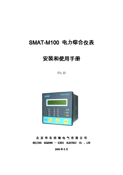
SMAT-M100 电力综合仪表安装和使用手册(V4.0)北京华东西瑞电气有限公司BEIJING HUADONG — XIRUI ELECTRIC CO. , LTD2006年5月目录1.概述 (1)1.1 简介 (1)1.2 主要特点 (1)2.功能 (3)2.1 测量功能 (3)2.2 显示功能 (4)2.3 继电器输出 (4)2.4 开关量输入 (4)2.5 通讯功能 (4)3.主要技术指标 (5)3.1 输入 (5)3.2 精度等级 (5)3.3 工作电源 (4)3.4 使用环境 (5)4.安装与接线 (6)4.1 现场安装 (6)4.1.1 外形尺寸及开孔尺寸 (6)4.1.2 端子定义 (6)4.2 电气连接 (7)4.2.1 PT和CT的连接 (7)4.2.2 通讯连接 (7)4.3 典型接线 (7)5.操作指南 (9)5.1 面板布置 (9)5.1.1 指示灯说明 (9)5.1.2 按键定义 (9)5.2 开机 (9)5.3 查询测量值 (10)5.4 系统设置 (11)5.4.1主菜单 (12)5.4.2编程步骤 (12)5.4.3 PT、CT变比及电压接线方式设置 (13)5.4.4 通讯设置 (14)5.4.5 显示格式设置 (14)5.4.6 时间设置 (14)5.4.7 清除电能数据 (14)1.概述1.1 简介SMAT-M100电力综合仪表(以下简称:SMAT-M100)是一种具有可编程功能、电量参数测量、遥信、遥控、LCD显示、电能累加、数据通讯等功能为一体的电力综合仪表。
它功能齐全,经济实用、可靠性高、抗干扰能力强,可完全取代常规的模拟式电表,是组成电气自动化系统的理想产品。
适用于35KV及以下各种电压等级的各种电力自动化系统。
SMAT-M100电综合力仪表1.2 主要特点1.2.1 测量功能强大SMAT-M100集合了电量变送器、数字式电度表、数显表、数据采集器等仪器的部分或全部功能,测量功能包括各种接线方式的全部相电压/线电压(V)、电流(I)、功率(P、Q、S)、电能(Wh、Qh)、功率因数(PF),频率(F)、零序电流(Io)及零序电压(Vo)的功能。
[精品]MCG-100W型使用说明
![[精品]MCG-100W型使用说明](https://img.taocdn.com/s3/m/1a582008c4da50e2524de518964bcf84b9d52d75.png)
MCG-100W型使用说明欢迎选用MCG-100W型无扎针电池波感应式木材测湿。
请使用前认真阅读本使用说明,以便获得正确的测量值。
一、名称与功能二、操作1、按ON键,电源接通,显示屏数字闪烁稳定后显示在00.0±0.3范围内(树种选择在任一档位)。
当离ON键后,约60秒电源自动切断,使电池能够获得更长的使用时间,进行自我保护。
提示:当按ON键几次后,测量仪显示屏仍然数字模糊或无数字显示,此时9V电池已耗尽,请更换电池。
2、当开机后,液晶显示屏不显示在00.0±0.3范围内请调整修正零位。
顺时针为正值,逆时针为负值。
3、由于MCG-100W型感应式木材测湿仪电磁波穿透深度为30mm,所以被测量木材厚度小于30mm时,要将木板悬空测量,或将木板叠加进行测量,叠加厚度不得小于30mm。
4、当调节树种选择开关后,仪器左侧的修正旋钮无法使显示器为零值时,可用一字起小心调节仪器右侧孔内的调节钮,顺时针为正值,逆时针为负值。
三、测量MCG-100W型仪表运用了美国哈里斯大规模集成电路技术,保证了木材水分测量的高灵敏度与精确度。
即使细微的含水率变化,仪器都能体现出来。
因此,它是准确度极高的木材测湿仪表。
为适应不同种密度木材的测量,在测湿仪的顶部设置了6个档位的树种选择开关,请按下列档位调整。
使用时请将仪器的底部平放在被检测的木材上,木材表面一定要平整,否则会出现测量误差。
如被检测木材的含水率不均匀,在测量时可多测几个点,然后算出平均值,以得到平均含水率。
提示:1、仪器应顺着木材纤维的方向进行测量。
2、木材表面要平整。
3、本仪器传感器在仪器底部的方框内(内藏式),尺寸为:长45mm,宽44mm。
故被检测木材的表面要大于传感器的表面。
4、被检测木材周围不能有其它物体,如铁质、具有磁性的感应物。
否则测量结果不准确。
5、该仪器电磁波穿透深度为30mm,故被检测木材厚度小于30mm时,应悬空测量或叠加至至少30mm。
- 1、下载文档前请自行甄别文档内容的完整性,平台不提供额外的编辑、内容补充、找答案等附加服务。
- 2、"仅部分预览"的文档,不可在线预览部分如存在完整性等问题,可反馈申请退款(可完整预览的文档不适用该条件!)。
- 3、如文档侵犯您的权益,请联系客服反馈,我们会尽快为您处理(人工客服工作时间:9:00-18:30)。
前 言感谢您购买、使用LU-M100系列单色液晶显示过程控制木芯检测仪。
本手册是关于LU-M100的功能、组态设置、接线方法和操作方法等的说明书。
除了此手册还有安东木芯检测仪上位机软件手册。
在操作之前,请仔细阅读有关说明书,以便正确使用。
在您阅读完本手册后,请妥善保管以便今后随时翻阅。
- V -确认包装内容打开包装箱后请首先确认以下事项。
一旦您收到的产品有误或者数量不对或者外观有问题,请及时与我们联系。
机 型在前面板的有“LU-M100”的符号。
如图1红色框中的标识。
具体型号请对照选型说明部分。
- VI -随机配件请参见随机的装机清单。
- VII -LU-M100系列功能特点LU-M100单色液晶显示过程控制木芯检测仪,集检测、记录与数据打印于一身,主要用于木材热处理的生产中。
4支PT100热电阻输入和仪表报警、控制输出,输入与输出完全隔离。
第一、第二通道检测木芯1、木芯2温度。
第三、第四通道检测环境湿度和环境(干球)温度。
并做到记录和打印数据的功能。
具有灵活的数据存储模式:记录的存储空间动态可调,每一通道都有独立可调的记录间隔;用户可根据需要选择通道和记录间隔进行数据存储。
大容量FLASH闪存芯片存储历史数据,掉电保存,内部存储时间可达140个小时至5600天。
具有方便的数据处理方式:直接连接微型打印机,打印用户指定时间的数据及曲线;通过RS232通讯接口与便携计算机、掌上电脑(PAD)连接,直接上传仪表的实时/历史数据,可通过上位机数据管理软件,对数据进行分析、存档、打印等处理;也可与组态王、MCGS等专业组态实时监控系统连接。
- VIII -具有强大的显示功能:特大数字显示、棒图显示、实时曲线显示、历史曲线显示、报警查寻、报警状态显示等,曲线画面均有缩放功能,并提供智能化历史趋势全自动回放功能,具有时间和幅度缩放功能,查找报警点极为方便,同时提供定位查寻功能,可直接查询某年、月、日、时、分、秒的数据,方便快捷;具有流量统计功能,可查寻任意时段的流量累积值;采用模块化设计,组配更加灵活,不同采集板可以同时使用;电源与采集板分层设计,输入与输出之间的电气完全隔离,大大提高仪表的可靠性。
同时具有中英双语显示界面。
- IX -目 录LU-M100系列功能特点................................................................................................................VIII目录.................................................................................................................................................X1.1使用注意事项 (14)1.2 仪表安装 (15)1.3 仪表外形 (17)1.3.1 前面板及功能介绍 (17)1.3.2 后面板及功能介绍 (18)1.4 仪表与外部的连接 (18)1.4.1电源线和通讯线的连接 (19)1.4.2信号输入部分的注意事项 (19)1.4.4接线方法 (20)1.5 工作参数指标 (22)- X -1.5.1系统工作参数 (22)1.5.2温度探头的安装方法 (22)1.5.3干湿球测湿度校准方法 (23)1.5.4干湿球测湿度维护介绍 (24)1.5.5 历史数据存储 (25)第二章 通用显示画面的介绍和基本操作 (25)2.1 概述 (25)2.2 开机画面及语言选择 (26)2.3 系统初始化错误画面 (27)2.4通道存储容量画面 (29)2.5 特大数据画面 (30)2.6 棒图画面 (32)2.7 实时曲线画面 (33)- XI -2.8 历史曲线画面 (35)2.9 打印设置画面及打印操作 (38)2.10 系统组态画面 (41)2.10报警查寻画面 (43)2.10.1 报警查寻 (43)2.10.2 报警查寻设置 (45)第三章 组态设置 (46)3.1 密码输入 (46)3.2系统组态(时间、密码、通讯设置) (48)3.2.1 参数项说明 (49)3.2.2 参数项操作说明 (50)3.2.3 清除历史数据 (52)3.2.4 保存/恢复出厂设置画面 (54)- XII -3.3 通道组态(通道参数设置) (56)3.3.1 901通道的参数说明 (59)3.3.2 通道参数修改操作说明 (62)3.3.3 控制方式 (63)3.3.4 参数拷贝 (64)第四章 数据存储 (66)4.1 内部FLASH功能说明 (66)第五章 通讯接口 (67)5.1 RS-232通讯方式 (67)5.2 RS-485通讯方式 (69)- XIII -第一章 使用前须知1.1使用注意事项在此,对使用LU-M100的注意事项进行说明。
使用前,请务必认真阅读。
仪表使用注意事项◆ 本仪表经过严格测试,如无严重损坏,一般不须做任何调整。
请您根据实际要求正确组态;◆ 将仪表移到温度或湿度偏差比较大的地方时,请先让本仪表通电半个小时以上以适应工作环境,再正常投入使用;◆ 本表中有一些塑料零部件,在清理时请用干燥的软布擦拭。
不能使用苯剂、稀薄剂等进行清理,否则会造成塑料零部件变色或变形;◆ 请不要将带电体靠近信号端子,否则会引起故障;◆ 请不要在LCD画面或者面板操作盘上沾上挥发性药品或者将橡胶和塑料与本表长时间接触,否则会引起故障;- 14 -◆ 本仪表采用微动键盘,请用户用手指轻轻触压,不要使用螺丝刀等硬物戳压键盘;◆ 本仪表使用的液晶屏不能压迫和碰撞;◆ 不使用本仪表时请务必切断电源;◆ 如果您确认是从表中冒烟、闻到异味或是发出异响等异常情况时,请立即切断电源,并及时与我公司技术部取得联系。
1.2 仪表安装在此,对LU-M100的安装场所和安装方法进行说明。
安装前请务必认真阅读。
安装场所请安装在下述场所:◆ 室内:温度0~45℃,湿度85%以下(无结露),避开风雨和阳光直射;◆ 由于仪表工作时会产生温升,请安装在通风良好的地方。
对于盘装式,请参照本说明书图1.2仪表外形尺寸及开孔尺寸。
对于便携式,建议您在本表的左右侧面和上方保留50mm以上的空隙;- 15 -◆ 请选择机械振动少的地方安装;◆ LCD具有背光照明的功能,允许在完全无光或光线较暗的环境下使用。
注意:◆ 如果在高温环境下长时间使用会缩短LCD的使用寿命(画面质量降低等); 请不要在下述场所安装本仪表:◆ 太阳光能直射到的地方、热器具的附近;◆ 油烟、蒸汽、湿气、灰尘、腐蚀性气体多的地方;◆ 电磁发生源的附近。
- 16 -- 17 -1.3 仪表外形1.3.1 前面板及功能介绍图1.3.1.1 LU-M100前面板前面板如图1.3.1.1所示,基本功能如下: ◆ LCD : 128*64单色液晶显示器;◆ 操作盘:通过操作盘上的按键对仪表进行相应的操作。
各个按键在各实时显示画面和组态画面具有不同的功能。
按键基本功能如下:¾ESC键:取消操作或返回上一级或作为翻页键;¾左移键:进行左移操作或跳到前一个菜单项;¾右移键:进行右移操作或跳到后一个菜单项;¾上升键:数值上升或跳到上一行菜单项;¾下降键:数值下降或跳到下一行菜单项;¾确认键:确认事件。
1.3.2 后面板及功能介绍后面板如图1.3.2.1所示,采集板的端口包括:外部信号的输入和控制信号的输出、系统电源输入及通讯等;其中大写数字分别表示采集板的板号,采集板数目(最多二块采集板)可根据需要进行配置,具体的连接方法请参见1.4章节。
从图中可看出,此仪表底部的1、2脚为电源供电部分,上部为采集板位置,上一排为输出(B1~B8),下一排为输入(A1~A8)。
1.4 仪表与外部的连接注意事项:- 18 -为了防止触电,请确保在电源切断的状态下进行接线操作!1.4.1 电源线和通讯线的连接电源线的输入端子位于仪表背面的左下方如图1.3.2.1。
1、2脚接交流220。
供电电源:85-264VAC,12W,50Hz±1Hz。
1.4.2 信号输入部分的注意事项请注意在测量回路中不要混入干扰:◆ 测量回路与电源供给线(电源回路)或者接地回路分开;◆ 确保测量对象不是干扰源,一旦无法避免,请将测量对象和测量回路隔离,并将测量对象接地;◆ 由静电感应产生的干扰,最好使用屏蔽线。
根据需要,请将屏蔽线与本仪表的地线端连接(注意请不要两点接地);◆ 由电磁感应产生的干扰,如果将测量回路接线等距离密集绞接比较有效。
- 19 -- 20 -1.4.4 接线方法温度探头的接线 1.木芯温度探头的接线将木芯温度探头(较长的两组)接在仪器后面板的“木芯1”(A1、A3、A5端)及“木芯2”(A9、A11、A13端)上,A1、A3、A9、A11端分别接红色线, A5、A13接白色线。
通道1 木芯1100输入通道2 木芯2100输入通道1 木芯1上限报警通道1 木芯1下限报警通道2 木芯2上限报警通道2 木芯2下限报警通道3湿球温度100输入通道4 干球温度100输入通道4 干球温度位式控制2.干、湿球温度探头的接线将两组温度探头(较短的两组)分别接在仪器原面板上的“湿球温度”端子(A2、A4、A6 )和“干球温度”(A10、A12、A14)上, A2、A4、A10、A12端分别接红色线, A6、A14接白色线。
控制输出的接线1.B1、B3是木芯1的上限报警控制接线端,B5、B7是木芯1的下限报警控制接线端,B9、B11是木芯2的上限报警控制接线端,B13、B15是木芯2的下限报警控制接线端。
2.B2、B4是环境(干球)温度的位式控制接线端。
3.打印机和外部通讯共用仪表的RS232通讯端。
使用打印机时,要短接B12、B20端和B14、B18端。
使用外部通讯时,要断开B12、B20端和B14、B18端的短接线,再连接B16(GND),B18(TXD),B20(RXD)到PC 机的串口GND(5),RXD(2),TXD(3)脚。
如果需要485通讯,可以特殊定制。
- 21 -1.5 工作参数指标1.5.1系统工作参数1.温度测量范围:0-100℃2.温度基本误差:±1℃3.湿度测量范围:0-100%RH4.湿度分辨力:1%RH5.采集周期:0.5秒6.电源:AC220V±%10,50Hz±2Hz以上参数在大气压力100KP,干湿球系数0.662*E-3,风速2.5M/S的条件下测定。
