340S8 Service Manual
MIL-S8TA 8-Port 10 100 1000 BASE-T 未管理开关用户指南(Rev.

MIL-S8TA8-Port 10/100/1000 BASE-T Unmanaged Switch User GuideRev. A22012-09-17Regulatory Approval- FCC Class A- UL 1950- CSA C22.2 No. 950- EN60950- CE- EN55022 Class A- EN55024Canadian EMI NoticeThis Class A digital apparatus meets all the requirements of the Canadian Interference-Causing Equipment Regulations.Cet appareil numerique de la classe A respecte toutes les exigences du Reglement sur le materiel brouilleur du Canada.European NoticeProducts with the CE Marking comply with both the EMC Directive (89/336/EEC) and the Low Voltage Directive (73/23/EEC) issued by the Commission of the European Community Compliance with these directives imply conformity to the following European Norms:EN55022 (CISPR 22) - Radio Frequency InterferenceEN61000-X - Electromagnetic ImmunityEN60950 (IEC950) - Product SafetyFive-Year Limited WarrantyTransition Networks warrants to the original consumer or purchaser that each of it's products,and all components thereof, will be free from defects in material and/or workmanship for aperiod of five years from the original factory shipment date. Any warranty hereunder isextended to the original consumer or purchaser and is not assignable.Transition Networks makes no express or implied warranties including, but not limited to, anyimplied warranty of merchantability or fitness for a particular purpose, except as expressly setforth in this warranty. In no event shall Transition Networks be liable for incidental orconsequential damages, costs, or expenses arising out of or in connection with theperformance of the product delivered hereunder. Transition Networks will in no case coverdamages arising out of the product being used in a negligent fashion or manner.TrademarksThe MiLAN logo and Transition Networks trademarks are registered trademarks of Transition Networks in the United States and/or other countries.To Contact Transition NetworksFor prompt response when calling for service information, have the following information ready:- Product serial number and revision- Date of purchase- Vendor or place of purchaseYou can reach Transition Networks technical support at:E-mail:**********************Telephone: +1.800.260.1312 x 200Fax: +1.952.941.2322Transition Networks6475 City West ParkwayEden Prairie, MN 55344United States of AmericaTelephone: +1.800.526.9267Fax: : +1.952.941.2322*******************© Copyright 2006 Transition NetworksThis equipment has been tested and found to comply with the limits for a class A device, pursuant to part 15 of the FCC rules. These limits are designed to provide reasonable protection against harmful interference in a commercial installation. This equipment generates uses and can radiate radio frequency energy and, if not installed and used in accordance with instructions, may cause harmful interference on radio communications. Operation of this equipment in a residential area is likely to cause harmful interference, in which case, the user will be requires to correct the interference at the user’s own expense.Content Introduction (1)Features (1)Package Contents (2)Hardware Description (3)Physical Dimensions (3)Front Panel (3)LEDs Indicators (3)Rear Panel (4)Installation (6)Attaching Rubber Feet (6)Mounting on the Wall (6)Power On (7)Technical Specification (8)IntroductionThe 8-port 10/100/1000BASE-T Switch with Auto MDI/MDIX is an unmanaged multi-port Switch that can be used to build high-performance switched networks. This switch is a store-and-forward device that offers low latency for high-speed networking. The Switch is designed for the core of the network backbone computing environment to solve traffic block problems at SME (small, medium enterprise) businesses.The 8-port 10/100/1000BASE-T Switch features a “store-and-forward”switching technology. This allows the switch to auto-learn and store source addresses in an 8K-entry MAC address table.Features⏹Conforms to IEEE 802.3, 802.3u, 802.3ab and 802.3x⏹8 Gigabit copper SOHO switch, compact size with universal internalpower⏹Auto-MDIX on all ports⏹16 Gbps back-plane⏹ N-Way Auto-Negotiation⏹8K MAC address table⏹Back pressure half duplex⏹Flow control full duplex⏹ Store-and-Forward switching architecture⏹ 144Kbytes memory buffer⏹True non-blocking switching⏹Support 8Kbytes Jumbo Frame1Package ContentsUnpack the contents of the switch and verify them against the checklist below.⏹ 8-port Switch⏹Power Cord.⏹User Guide.8-port Switch Power Cord User manualPackage ContentCompare the contents of your switch package with the standard checklist above. If any item is missing or damaged, please contact your local dealerfor service.23Hardware DescriptionPhysical DimensionsThe physical dimensions of the Switch is 165mm x 100mm x 32.5 mm (L x W x H)Front PanelThe front panel of the 8-Port Gigabit switch consists of LED-indicators (100/1000, Link/Activity, Full duplex/Collision) for each Gigabit port and power LED-indicator for unit.RJ-45 Ports (Auto MDI/MDIX): 8 10/100/1000 N-way auto-sensing for 10Base-T, 100Base-TX or 1000Base-T connections. (In general, MDI means connecting to another Hub or Switch while MDIX means connecting to a workstation or PC. Therefore, Auto MDI/MDIX allows you to connect to another Switch or workstation without changing to non-crossover or crossover cabling.)LEDs IndicatorsThe LED Indicators gives real-time information of systematic operation status. The following table provides descriptions of LED status and their meaning.Green PowerOnOff Power is not connectedGreen The port is operating at the speed of 1000Mbps.Orange The port is operating at the speed of 100Mbps.Off No device attached or in 10Mbps modeGreen The port is connecting with the device.Blinking The port is receiving or transmitting data.Off Nodeviceattached.Orange The port is operating in Full-duplex mode.Blinking Packet collision occurred on this port.Off No device attached or in half-duplex mode. Rear PanelThe rear panel of the 8-port Gigabit Switch consists of 8 auto-negotiation 10/100/1000Mbps Ethernet RJ-45 connectors (support Automatic4MDI/MDIX function).RJ-45 Ports (Auto MDI/MDIX): 8 port auto-negotiation 10/100/1000 Mbps Ethernet RJ-45 connectors[Auto MDI/MDIX means that you can connect to another Switch or workstation without changing non-crossover or crossover cabling.]5InstallationThis section shows the installation procedures of the switch.Set the Switch on a sufficiently large flat space with a power outlet nearby.The surface where you put your Switch should be clean, smooth, level, and sturdy. Make sure there is enough clearance around the Switch to allow attachment of cables, power cord and air circulation.Attaching Rubber FeetA. Make sure mounting surface on the bottom of the Switch is grease anddust free.B. Remove adhesive backing from your Rubber Feet.C. Apply the Rubber Feet to each corner on the bottom of the Switch.These footpads can prevent the Switch from shock/vibration. Mounting on the WallThe switch can be mounted on the wall. The switch has two wallmountbrackets included in the package.Power OnConnect the cord of power to the power socket on the rear panel of the Switch. The other side of power cord connects to the power outlet. Check the power indicator on the upper panel to see if power is properly supplied.7Technical SpecificationThe following table provides the technical specification of 8-ports Gigabit Switch.IEEE 802.3 10BASE-T EthernetIEEE 802.3u 100BASE-TX Fast EthernetIEEE 802.3ab Gigabit EthernetIEEE 802.3x Flow Control and Back-pressureCSMA/CDStore-and-Forward switching architecture14,880 pps for 10Mbps148,800 pps for 100Mbps1,488,000 pps for 1000MbpsRJ-45; Auto-MDIX on all ports8K Mac address table144Kbytes memory bufferSupports 8Kbytes jumbo packet size16Gbps810BASE-T: 2-pair UTP/STP Cat. 3, 4, 5 cable EIA/TIA-568 100-ohm (100m)100BASE-TX: 2-pair UTP/STP CAT. 5 cable EIA/TIA-568 100-ohm (100m)Gigabit Copper: 4 pair UTP/STP CAT. 5 cable EIA/TIA 568 100-ohm (100M)Per port: 100/1000, Link/Activity, Full duplex/ CollisionPer unit: PowerAC 110~240V, 50/60Hz7.6 Watt (maximum)0℃ to 45℃ (32℉ to 113℉)-40℃ to 70℃ (-40℉ to 158℉)10% to 90% (Non-condensing)0% to 95% (Non-condensing)165mm x 100mm x 32.5mm (L x W x H) Compliance with FCC Class A, CE Compliance UL, cUL,CE/EN609509。
ssp340_迈腾电气设备

在迈腾中延续体现了在汽车电气设备和电子装置领域中的革新。
其中,舒适性作为革新的焦点,在研发过程中尤其受到重视。
例如,进入和起动许可开关在此被称为免旋转点火钥匙,该装置是首次投入使用。
该自学教程将帮助您了解迈腾所使用的电气设备,并且熟悉其中的更新内容。
S340_07223简介 . . . . . . . . . . . . . . . . . . . . . . . . . . . . . 4数据总线系统在驱动 CAN 数据总线中的控制单元 . . . . . . . . . . . . . . . 8在舒适 CAN 数据总线中的控制单元 . . . . . . . . . . . . . . .10在信息娱乐 CAN 数据总线中的控制单元,组合仪表和诊断 . . . . . . . . . . . . . . . . . . . . . . .12子总线系统 . . . . . . . . . . . . . . . . . . . . . . . . .14车载电网电控箱. . . . . . . . . . . . . . . . . . . . . . . . . . . .18继电器支架和保险丝盒 . . . . . . . . . . . . . . . . . . . .20车载电网控制单元 . . . . . . . . . . . . . . . . . . . . . .22外车灯 . . . . . . . . . . . . . . . . . . . . . . . . . . .24数据总线诊断接口 . . . . . . . . . . . . . . . . . . . . . .32组合仪表中的控制单元 . . . . . . . . . . . . . . . . . . . .34舒适系统的中央控制单元 . . . . . . . . . . . . . . . . . . .38防盗锁止系统(WFS) IV . . . . . . . . . . . . . . . . . . . .40Start-Stop 无钥匙启动系统 . . . . . . . . . . . . . . . . . .44电控转向柱锁止系统 (ELV) . . . . . . . . . . . . . . . . . .舒适便捷功能和安全电子装置转向灯系统(Advanced-Frontlighting-System 高级前灯照明系统) .个性化 . . . . . . . . . . . . . . . . . . . . . . . . . . .驻车辅助装置 . . . . . . . . . . . . . . . . . . . . . . . .逆变器 . . . . . . . . . . . . . . . . . . . . . . . . . . .54保养. . . . . . . . . . . . . . . . . . . . . . . . . . . . . 56考考你. . . . . . . . . . . . . . . . . . . . . . . . . . . . 58一览4安装位置迈腾的车载电网是分散式结构的,与高尔夫 2004 车型所使用的车载电网相似。
CL408E服务手册
上海立象信息技术有限公司
14.如何测试打印头的质量 ....................................................................................................... 20 B 具体报错内容如下:...............................................................................................................20
六.基本测试打印及检测 ...................................................................................................................12
A.恢复系统的某些设置: ............................................................................................................12 1.清除到出厂模式: ...................................................................................................................12 2.清除 EEP_POM .....................................................................................................................13 3.打印头的测试......................................................................................................................... 13 4.DISPENSE COUNTER 测试 ................................................................................................14 5.CUTTER COUNTER 测试 ....................................................................................................14 6.修改电压................................................................................................................................. 14
SL2.2S规格书,usb HUB大全,替换FE1.1S,GL850,GL852,PL2586
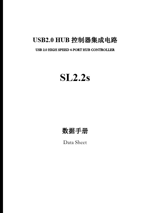
USB2.0 HUB控制器集成电路USB 2.0 HIGH SPEED 4-PORT HUB CONTROLLERSL2.2s数据手册Data Sheet内容目录第一章管脚分配 (3)1.1 SL2.2S管脚图 (3)1.2 SL2.2S管脚定义 (3)第二章 功能叙述 (5)2.1综述 (5)2.2指示灯 (5)2.2.1单灯方案 (5)2.2.2多灯方案 (6)2.2.3 LED指示定义 (6)2.3过流保护 (6)2.4充电支持 (6)2.5I2C接口 (7)2.6EEPROM设置 (7)第三章电气特性 (8)3.1极限工作条件 (8)3.2工作范围 (8)3.3直流电特性 (8)3.4HS/FS/LS电气特性 (8)3.5ESD特性 (8)附录一封装 (9)表格目录表格1: 端口LED定义 (6)表格 2 : ACTIVE LED定义 (6)表格3:EEPROM数据结构定义 (7)表格4: 最大额定值 (8)表格5: 工作范围 (8)表格6: 直流电特性 (8)插图目录图1:SSOP28 管脚图 (3)图2:单灯方案配置 (5)图3: 5灯方案配置 ............................................................................... (6)图 4:附录 封装图 ................................................................................... .9第一章管脚分配1.1SL2.2s管脚图图1:SSOP28 管脚图1.2SL2.2s管脚定义管脚名称28Die IO类型定义Pin#VSS 1 P 芯片地XOUT 2 O晶振PAD XIN 3 IDM4 4 B下行口4的USB信号DP4 5 BDM3 6 B下行口3的USB信号DP3 7 BDM2 8 B下行口2的USB信号DP2 9 BDM1 10 B下行口1的USB信号DP1 11 BVDD18 12 P 模拟1.8vVDD33 13 P 模拟3.3v - 14 NCUDM 15 B上行口的USB信号UDP 16 BRESET_N 17 I,Pu 芯片外部复位输入- 18 NCPSELF 19 I,Pu 高为自供电,低为总线供电VDD5 20 P 5v输入VDD33 21 P 3.3v输出DRV 22 B,Pu 点灯驱动信号LED1 23 B,Pu 点灯驱动信号LED2 24 B,Pu 点灯驱动信号PWRN 25 B,Pu 下行口电源输出控制,低有效OVCRN/SDA 26 B,PuI2C SDA数据线,内部上拉;芯片初始化完成后作为过流保护输入脚,低有效SCL 27 B,Pu I2C SCL时钟输出VDD18 28 P 数字1.8v注释:O,输出;I 输入;B 双向;P 电源/接地;Pu 上拉;Pd 下拉;NC 悬空;第二章 功能叙述2.1综述SL2.2s 是一颗高集成度,高性能,低功耗的USB2.0集线器主控芯片;该芯片采用STT 技术,单电源供电方式,芯片供电电压为5v , 内部集成5V 转3.3V,只需在外部电源添加滤波电容;芯片自带复位电路,低功耗技术让他更加出众。
GS-2406T PLUS GS-3405T PLUS Series 热转式 热感式 SUR

GS-2406T PLUS / GS-3405T PLUS / Series热转式/热感式SURPASS PLUS条码印表机使用手册Ver.1.1.3Agency Compliance and ApprovalsEN 55032, Class AEN 55024This is a class A product. In a domestic environment this product may cause radiointerference in which case the user may be required to take adequate measures.FCC part 15B, Class AThis equipment has been tested and found to comply with the limits for a Class Adigital device, pursuant to Part 15 of the FCC Rules. These limits are designed toprovide reasonable protection against harmful interference when the equipment isoperated in a commercial environment. This equipment generates, uses, and canradiate radio frequency energy and, if not installed and used in accordance with themanufacturer’s instruction manual, may cause harmful interference with radiocommunications. Operation of this equipment in a residential area is likely to causeharmful interference, in which case you will be required to correct the interference atyour own expense.FCC 符合声明此设施符合第15 部份的规则。
百斯巴特服务盘中英文对照

百斯巴特定位仪维修服务盘中英文对照对于ML4600-8型(包括VAG1995, Formel2000, ML4600-8,Millennium, 百年版)定位仪,由于设备直接带有键盘,因此可直接进入下面过程。
但对于ML4000型(包括VAG1813, ML4001,KDS)定位仪,由于其只配备了光电板,而没有键盘,所以必须另外准备一个接口为大口的键盘。
(早期计算机都使用大口键盘,现在一般都使用PS2接口的键盘,接口外形比大口键盘要小。
若找不到大口键盘,可想办法找一根大小键盘接口转接线。
)进入计算机中的DOS状态的方法如下:开机进入定位仪程序准备状态主画面之后,先按住键盘上的“Back Space”键(即向前删除一格键)不松手,然后下键盘上的“E”键,则定位仪程序退出到DOS状态,屏幕上显示为C:\ML>。
把服务盘插入计算机软驱(服务盘的写保护应该打开),开启主机电源,服务盘会自动引导启动过程(如果引导程序失效,而软盘内容可在DOS状态下读出,则请在A:>的状态下键入A:>auto,然后按回车键),最后在屏幕上出现以下画面:说明:重装软件程序能够删除掉硬盘中原来所装的定位仪程序或数据,然后把软件盘插入计算机软驱,重新启动,安装程序。
也可以不用此重装软件的程序,直接把软件盘插入计算机软驱,重新启动,安装程序。
新安装的程序会自动覆盖掉老程序。
读通讯板序列号的程序可以读出通讯板内所写的设备序列号,如果是通用通讯板,则读出结果为:universal.按0键可以退出服务程序,返回到DOS状态。
6,7,8,9为特殊功能,请勿使用。
常用的操作是2-更换传感器主板和3-更换传感器镜头。
以下一一举例。
一:更换传感器主板按键盘上的2键,程序自动进入更换传感器主板的步骤。
屏幕显示的中英文对照如下所示:二:更换传感器镜头按键盘上的3键,程序自动进入更换传感器主板的步骤。
屏幕显示的中英文对照如下所示:在操作过程中可能出现的错误提示为:三:更换通讯板:说明:更换通讯板必须使用通用通讯板。
TM57PA20_TM57PA40中文资料

7. 指令表 ......................................................................................................................... 27
8. 电气特性...................................................................................................................... 39
Service Master诊断仪说明书
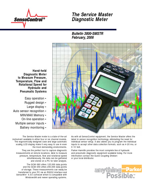
Bulletin 3800-SMSTR February,2006Hand-heldDiagnostic Meter to Measure Pressure, Temperature, Flow and Rotational Speed forHydraulic and Pneumatic Systems Easy operation •Rugged design •Large display •Auto sensor recognition •MIN/MAX Memory •On-line operation •Multiple sensor inputs •Battery monitoring •As with all SensoControl equipment, the Service Master offers the latest in sensor recognition technology, eliminating the need for individual sensor setup. It also allows you to program the individual inputs to accept other data collection formats, such as 4-20 ma, or 0-10 Volt.Parker Hannifin provides the most complete line of hydraulic and pneumatic diagnostic equipment available today. For more information contact the Quick Coupling DIvision or your local distributor.The Service Master meter is a state-of-the-artinstrument available in either four or six channel models.The ergonomically designed case and large automatic scaling LCD display make it very easy to use in eventhe most demanding environments.They are the perfect tool to capture diagnostic measurements at remote locations. Able to measurepressure, temperature, flow and rotational speedsimultaneously, the data can be gatheredand stored on a PC for later analysis.The SCM-360 offers 125,000 data points and the SCM-450 offers 250,000 data points of storage. These measurements can easily be transferred to your PC via an RS232 interface and SensoWin“ 4.03 software which is compatible withWindows98 and newer operating systems.SensoControl Service Master SchematicMeasures and Documents Flow, Pressure, Voltage, Current, Temperature and Rotation speedSensoControl Service Master Diagnostic MeterMeter•Digital LCD Text Display - 128x64 pixels•Automatic Character Height Scaling •Display of Pressure, Temperature,Flow and Rotational Speed - Pressure in PSI and Bar - Temperature in °F and °C - Flow in GPM and l/min.- Rotational Speed in RPM Inputs•Four or six, 5-pin push-pull style connectors•Automatic Sensor Recognition •0-3 Volts (R=470 k )•12 Bit A/D Converter•1 ms Scanning Rate (1-3 inputs)•2 ms Scanning Rate (4-6 inputs)Functions•Differential Value Measurement •MIN/MAX Memory •Online data transfer •Battery level indicator•Power calculation (display only)•Flow run-out (display only)•Auto power offOutput•RS232 interface•Adjustable baud rate up to 38400 BPS•8 data bits, 1 stop bitPower Requirements•Internal 7.2-volt rechargeable Ni-Cad battery•Recharge circuit for use with external power supply.•Operating time (Aprox. 5 hours)•Excitation voltage (12-30 VDC)Memory Functions •Memory capacity- 125,000 data points (SCM-360)- 250,000 data points (SCM-450)•Memory used in 25,000 data point intervals•Variable storage rate•Variable measuring period up to 100 hours•Manual and automatic triggering Ambient Conditions•Operating Temperatures 32°F to 122°F (0°C to 50°C)•Storage Temperatures-4°F to 140°F (-20°C to 60°C)•Protection class IP54Housing•Glass reinforced polyamide •11-Key tactile touch membrane •EMC Protection- Electromagnetic interference (DIN/EN 50081, Part 1)- Immunity to emitted interference (DIN/EN 50082, Part 2)Dimensions•Length/Height/Width - 9.25 x 4.19 x 2.09- (235 x 106 x 52 mm)Weight• 1.2 lbs (700 grams)Function Descriptions1ON/OFF Turns meter on or off2SETUP/OPTION Change system settings 3/4ARROWS Select line and function values5START/ENTER Change function values and start measurements 6STOP/ESC Stop or terminate functions7I1-I2Differential value between input 1 and input 2.8TEMP Displays the measured temperature values for all channels 9DATA-OUTPUT Displays output to PC, printer or graphic display 10RECORD To record and store measurements11MIN/MAX/ACTUAL Displays the minimum, maximum and actual values. Reset deletes values 12INPUTS Inputs for up to (6) sensors1311-30 VDC Input for external power supply and charging of internal battery14DATA OUTPUT RS232 port for connecting to the PC, printer, or external trigger module15GRAPHIC LCD Displays measured values, adjustment menus and graphics.16ADDITIONAL LINE Displays the power or flow runout values.17STATUS LINE Shows the designation of the measured value or the menu name.Technical DataTemperature Sensorfor Serviceman and Service Master. Can be used with Parker flow sensors or with an SCTA-1/4 port adapter. Accuracy:+– 1.5% Full scaleTemperature range: -13°F to 257°F(-25°C to 125°C)Part NumberSCT -150-04-02Accessories Expand the FunctionaliSpecial Note: All Parker SensoControl hand-held diagnostic meters are now equipped with the same 5-pin push-pull style connector ports. Accessories such as pressure sensors, temperature sensors, flow meters, tachometers and cables are all interchangeable between Serviceman and Service Master meters.Pressure Transducer OptionsTransducerPD✳✳-0600PD ✳✳ -1500PD ✳✳ -10000ity of the Service MasterTachometer AdaptersContact adapter for belt drive wheel.Part NumberSCRPMA-001Focus adapter for confined areas.Part NumberSCRPMA-001Technical DataMeasuring Range . . . . . . . . . . . . . . .20 10,000 RPM Measuring Distance . . . . . . . . . . . . . . . . . .0.1 19.5 in Accuracy . . . . . . . . . . . . . . . . . . . . . . . . . . . . . . ..0.5xcitation Voltage . . . . . . . . . . . . . . . . . . . . . 9 VDC utput Signal . . . . . . . . . . . . . . . . . . . . . . . .0 3 VDC Resolution . . . . . . . . . . . . . . . . . . . . . . . . . . . . .5 RPMSCRPM Tachometerfor Serviceman and Service Master Meters.Displays a precision measurement of rotational speed. 5-pin push-pull style connector.Part NumberSCRPM-220Voltage Adapterfor use with Auxiliary Sensors to Serviceman and Service Master Input 0 - 20 MA or 0 - 10 VDC Accuracy 0.25 FSPart NumberSCMA-VADC-250•Six measurement ranges: Vacuum to 14,500 PSI•Color coded for easy identification•Corrosion resistant stainless steel housing •Accuracy of .5% Full Scale (FS)•Available with PD, PDP or EMA style diagnostic couplingsSensoWIN ™4.03 Softwarefor data transfer to a PC Windows 98 and newerPart NumberSCSW-400SensoControl Flow SensorsThese flow sensors are a compact light-weight aluminum diagnostic tool capable of measuring pressure, temperature and flow from a single test These flow sensors are designed to be used with a wide variety of hydraulic fluids. This design also es the effect of viscosity changes. These units are manufactured from solid aluminum and They are es with flow measuring Flow sensors are provided with a choice of MA style diagnostic ports and are designed to be used with Serviceman Material SpecificationsFlow lock . . . . . . . . . . . . . . . . . . . .Anodi ed Aluminum Turbine . . . . . . . . . . . . . . . . . . . . . . . . . . .Stainless Steel . . . . . . . . . . . . . . . . . . . . . . . . . . . . .6000 PSI* SCFT–7160 is rated to 5000 PSI5 pin to 5 pin CablesFlow sensor, transducer andtemperature probe cables for both Serviceman and Service Master.LengthPart Number10 ft 3 m SC -102-03-02Extension Cable16.4 ft 5 m SC -102-05-12AdaptersSee Catalog 3800 for the available adapters used in con unction with Service Master diagnostic equipment.Bulletin 3800-SMSTRParker Hannifin CorporationQuick Coupling Division 8145 Lewis RoadMinneapolis,MN 55427Phone:763-525-4240Fax:763-544-3418/quickcouplingsPRINTED IN U.S.A. GR, AP 5M 08/05Service Master Test Meter KitsAdditional TransducersFlow SensorsService Master 360Service Master 450Kit Contents:Meter Kit Meter Kit CaseSC-690SC-690Service Master Meter SCM-360-1-01SCM-450-1-01T ransducers (Quantity 2)(See Below)(See Below)Transducer Cable, 10’(Quantity 2)SCK-102-03-02SCK-102-03-02Power Supply – Meter*SCSN-450SCSN-450SensoWin Software 4.03SCSW-400SCSW-400Computer Interface Cable SCK-313-02-31SCK-313-02-31Operating Manual** Included with Service Master MeterCode for OrderingService Master Meter Kits:PDSM XX - X - XX - XXCODE PRESSURE COLOR01-14.5 – +145 PSIBlue 060 – 870 PSI Green 150 – 2175 PSI Y ellow 400 – 5800 PSI Orange 600 – 8700 PSI RedCODE DESCRIPTION36Service Master 360 Meter 45Service Master 450 MeterCODE DESCRIPTION2PD Style 4PDP Style6EMA3 Style (Female)Transducer Pressure Range(Choose two)Diagnostic Style Meter StyleCode for Ordering Separately:SCFT -XXXX - XXXCODE DESCRIPTIONPD PD Style PDP PDP Style EMA EMA StyleFlow RangeCODEFLOW RATE00040.2 – 4 GPM (1 – 15 l/min)0116 1 – 16 GPM (4 – 60 l/min) 0380 3 – 80 GPM (10 – 300 l/min)5160 5 – 160 GPM (20 – 600 l/min)Diagnostic StyleCode for Ordering Separately:PD XXXXXX - XXXXCODEDESCRIPTIONTA PD Style PTA PDP StyleTEMA3EMA3 Style (Female)Diagnostic StyleCODE PRESSURE COLOR0100-14.5 – +145 PSI Blue06000 – 870 PSI Green 15000 – 2175 PSI Y ellow 40000 – 5800 PSI Orange 60000 – 8700 PSI RedPressure RangePTA - 10000DIRECT PORT ONL Y (1/2-14BSPP Thread)PRESSURE COLOR0 – 14500 PSI RedPressure RangeDiagnostic Style。
AO3404 规格书 AOS
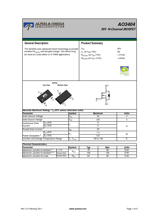
Power (W)
10000 1000
TA=25°C
100
10
1
0.00001 0.001
0.1
10
1000
Pulse Width (s) Figure 11: Single Pulse Power Rating Junction-to-
Ambient (Note F)
In descending order D=0.5, 0.3, 0.1, 0.05, 0.02, 0.01, single pulse
Ciss
Input Capacitance
Coss
Output Capacitance
Crss
Reverse Transfer Capacitance
Rg
Gate resistance
VGS=0V, VDS=15V, f=1MHz VGS=0V, VDS=0V, f=1MHz
255 310 pF
45
AO3404
30V N-Channel MOSFET
General Description
Product Summary
The AO3404 uses advanced trench technology to provide excellent RDS(ON) and low gate charge. This device may be used as a load switch or in PWM applications.
ID=-250µA, VGS=0V
30
IDSS
Zero Gate Voltage Drain Current
VDS=30V, VGS=0V
TJ=55°C
官方说明书FAIRCHILDFDN340P说明书

FAIRCHILD FDN340P Manual/file/2556701From collects and classifies the global productinstrunction manuals to help users access anytime andanywhere, helping users make better use of products.Home: / Chinese: /September200Ω@V GS=–4.5 VmΩ@V GS=–2.5 Vpi c a l).h n olog y f or ex tremelyu m Ra t i n g sPa r a m e t ee Volta g ee Volta g erren t– Con ti n u ou s– Pu ls edi pa ti on f or Si n g le Operan d Stora g e Ju n c ti on FDN340PFebruary 2007FDN340P Rev E 1Electrical CharacteristicsT A = 25°C unless otherwise notedSymbolParameterTest ConditionsMinTyp Max UnitsOff CharacteristicsBV DSS Drain–Source Breakdown VoltageV GS = 0 V, I D = –250µA–20V∆BV DSS ∆T J Breakdown Voltage Temperature CoefficientI D = –250µA,Referenced to 25°C –12mV/°C V DS = –16 V,V GS = 0 V –1µA I DSS Z ero Gate Voltage Drain Current V DS = –16 V, V GS = 0 V,T J =55°C –10I GSSF Gate–Body Leakage, Forward V GS = 8 V, V DS = 0 V 100nA I GSSR Gate–Body Leakage, ReverseV GS = –8 V,V DS = 0 V–100nA On Characteristics(Note 2)V GS(th)Gate Threshold Voltage V DS = V GS , I D = –250µA–0.4–0.8–1.5V ∆V GS(th) ∆T J Gate Threshold Voltage Temperature Coefficient I D = –250µA,Referenced to 25°C 3mV/°C V GS = –4.5 V, I D = –2 A 6070m ΩV GS = –4.5 V,I D = –2 A,T J =125°C 77120R DS(on)Static Drain–Source On–Resistance V GS =–2.5 V, I D = –1.7A,82110I D(on)On–State Drain Current V GS = –4.5 V,V DS = –5 V–5A g FS Forward Transconductance V DS = –4.5 V, I D = –2 A9S Dynamic Characteristics600Input Capacitance 779pF 175Output Capacitance121pF 80Reverse Transfer CapacitanceV DS = –10 V, V GS = 0 V,f = 1.0 MHz56pFSwitching Characteristics(Note 2)t d(on)Turn–On Delay Time 1020ns t r Turn–On Rise Time 910ns t d(off)Turn–Off Delay Time 2743ns t f Turn–Off Fall Time V DD = –10 V,I D = –1A,V GS = –4.5V,R GEN = 6 Ω1120ns Q g Total Gate Charge 7.210nC Q gs Gate–Source Charge 1.7nC Q gd Gate–Drain ChargeV DS = –10V,I D = –3.5 A,V GS = –4.5 V1.5nC Drain–Source Diode Characteristics and Maximum RatingsI S Maximum Continuous Drain–Source Diode Forward Current –0.42A V SDDrain–Source Diode Forwa rdVoltageV GS = 0 V,I S = –0.42 A(Note 2)–0.7–1.2V Notes:1.R θJA is the sum of the junction-to-case and case-to-ambient thermal resistance where the case thermal reference is defined as the solder mounting surface of the drain pins. R θJC is guaranteed by design while R θCA is determined by the user's board design.a. 250°C/W when mounted on a0.02in 2 pad of 2 oz copper b. 270°C/W when mounted on a .001 in 2 pad of 2 oz copperScale 1 : 1 on letter size paper2.Pulse Test: Pulse Width < 300µs, Duty Cycle < 2.0%FDN340PFDN340PFDN340P Rev E1FDN340PFDN340P Rev E1。
三星R408 R458说明书

R408/R458 User Guide用户指南更换零件和配件 18 法规符合性声明 21 WEEE 符号信息 30 基本部件 31 概览32 前视图32 状态指示灯 33 右视图 34 左视图 35 后视图(R408, 适用于支持一个电视输出端口的型号) 36 后视图(R458, 适用于支持一个 HDM I 端口的型号) 37 底视图38目录第 1 章 开始使目录1 安全注意事项4 操作计算机的正确姿势 13 重要安全信息 16 第 3 章 设置和产品规格LCD 亮度控制 51 BIOS 设置程序52 进入 BIOS 设置程序 52 BIOS 设置程序屏幕 54 设置引导密码 56 更改引导优先级 58 电池59 安装/卸下电池 59 对电池进行充电 60 测量剩余电池电量60 执行Ba tt er y C al ib r at io n 功能 61 使用安全锁端口 62 问题解答63 产品规格(R408) 64 产品规格(R 458)65打开计算机 39 打开计算机 39第 2 章 使用计算机键盘 41 触摸板44 CD 驱动器(ODD, 可选) 45 插入和弹出 CD 45 多卡插槽 47 Expr es s 卡插槽49第 1 章开始使用目录1安全注意事项4操作计算机的正确姿势13重要安全信息16更换零件和配件18法规符合性声明21WEEE 符号信息30基本部件31概览32前视图32状态指示灯33右视图34左视图35后视图(R408,适用于支持一个电视输出端口的型号)36后视图(R458,适用于支持一个HDMI端口的型号)37底视图38打开计算机39打开计算机39安全注意事项表示法图标表示法说明未能遵循标有此符号的说明可能会造成 警告 人身伤害或死亡。
未能遵循标有此符号的说明可能会造成 注意轻度人身伤害或财产损失。
文字表示法图标表示法 说明此部分中的内容包括使用某项功能前所版权© 2008 Samsung Electronics Co., Ltd.。
鸿锋 340 380 四 八端口固定式读写器 用户手册说明书

HF340/380鸿锋340/380四/八端口固定式读写器用户手册欢迎您成为鸿陆技术的用户!感谢选择多端口读写器鸿锋340/380希望给您的工作带来便利目录目录 (3)一、技术规格 (5)1.1产品特点 (5)1.2主要功能及技术性能 (5)1.2.1主要功能 (5)1.2.2性能参数 (5)1.2.3工作环境 (6)二、示意图 (7)2.1结构外形尺寸 (7)2.2重量参数 (7)2.3接口示意图 (7)2.3.1电源、通信及I/O接口 (7)2.3.2I/O接口定义 (8)2.3.3外接射频线缆说明(选配) (11)2.3.4网络应用连接示意图 (11)三、安装说明 (12)3.1注意事项 (12)3.2安装条件 (13)3.3设备连接 (13)3.3.1连接电源适配器或PoE交换机 (13)a.连接电源适配器 (13)b.连接PoE交换机 (13)3.3.2连接外部天线和射频电缆 (14)3.3.3连接PC机 (14)3.4安装设备 (15)3.5验收 (15)3.5.1结构验收 (15)3.5.2性能验收 (15)四、网页操作说明 (16)4.1系统登录 (16)4.1.1登录 (16)4.1.2系统导航 (16)4.2参数配置 (17)4.2.1天线配置 (17)4.2.2RFID配置 (18)4.2.3网络配置 (19)4.2.4高级输出配置 (20)4.2.5GPI配置 (21)4.2.5Web参数配置示例 (22)4.3系统管理 (25)4.3.1系统管理 (25)4.3.1.1时钟同步 (26)4.3.1.2应用软件升级 (26)4.3.1.3基带软件升级 (28)4.3.2密码修改 (30)五、常见故障 (31)5.1日常维护 (31)5.2常见故障分析及解决 (31)六、包装附件及运输和存储 (33)6.1 (33)6.2附件 (33)6.3存储要求 (34)七、售后服务 (35)一、技术规格1.1产品特点HF340/380是一款高性能超高频多端口固定式RFID读写设备,支持ISO18000-6C/6B、GB/T29768、GJB7377.1协议,工作频段支持国标双频920MHz~925MHz、840MHz~845MHz和FCC,902MHz~928MHz以及ETSI,865MHz~868MHz,输出功率0dBm~35dBm可调,具有识别距离远、速度快、多标签识别能力超强、抗干扰能力强、防护性能高和安装使用方便等特点。
阿斯科姆 asix4 使用手册说明书
asix4User’s Manual see and get more…S-BUS - Driver of S-BUS Protocol for SAIA-Burgess Electronics PLCsUser’s ManualDoc. No. ENP4051Version: 29-08-2005User’s Manual asix4 ASKOM® and asix®are registered trademarks of ASKOM Spółka z o.o., Gliwice. Other brandnames, trademarks, and registered trademarks are the property of their respective holders.All rights reserved including the right of reproduction in whole or in part in any form. No part of this publication may be reproduced or transmitted in any form or by any means, electronic or mechanical, including photocopying, recording, or by any information storage and retrieval system, without prior written permission from the ASKOM.ASKOM sp. z o. o. shall not be liable for any damages arising out of the use of information included in the publication content.Copyright © 2005, ASKOM Sp. z o. o., GliwiceASKOM Sp. z o. o., ul. Józefa Sowińskiego 13, 44-121 Gliwice, tel. +48 (0) 32 3018100, fax +48 (0) 32 3018101,.pl,e-mail:****************.plasix4 S-BUS - Driver of S-BUS Protocol for SAIA-Burgess…1. S-BUS - Driver of S-BUS Protocol for SAIA-Burgess Electronics PLCs1.1. Driver UseThe S-BUS driver is used for data exchange between PCD PLCs of SAIA-Burgess Electronics and an asix system computer.The S-BUS protocol is compatible to the specification "SAIA S-Bus for the PCD family", Edition 26/739 E2-05.96, developed by SAIA-Burgess Electronics.For purposes of communication with the asix system, the following interfaces of PCD PLCs may be used:- the PGU interface (RS-232C);- additional communication interfaces, the number and type of which depend on thecontroller type and configuration. These interfaces enable data transmission in one ofthe standards given below:RS-232C,RS-422,RS-485,current loop of 20 mA.NOTEFor data exchange you should use a cable made according to the specification PCD8.K111.See: Figure 1. Cable Compatible with the PCD8.K111 Specification..Figure 1. Cable Compatible with the PCD8.K111 Specification.1.2. Declaration of Transmission ChannelThe full syntax of declaration of transmission channel using the S-BUS protocol is given below:logical_channel_name=S-BUS, id, port [, baud]where:S-BUS - driver name;©ASKOM, Gliwice August 2005 3S-BUS - Driver of S-BUS Protocol for SAIA-Burgess…asix 44 August 2005 ©ASKOM , Gliwiceid - number of the controller in the S-BUS network; port - port name: COM1, COM2 etc.; optional parameters:baud - transmission channel.If the optional parameters are not given, then by default it is assumed as follows: transmission speed of 9600 baud.EXAMPLEThe declaration of the logical channel named CHAN1 operating according to the S-BUS protocol and exchanging data with the controller numbered 1 through the COM2 port with a speed of 9600 baud is as follows:CHAN1 = S-BUS, 1, COM2The S-BUS driver is loaded as a DLL automatically.1.3. Addressing the Process VariablesThe syntax of symbolic address which is used for variables belonging to the S-BUS driver channel is as follows:<type><index>where:type - variable type, index - index within the type.Symbols of variable types (the type of raw variable value is given in parentheses):C - values of counters (DWORD), F - states of flags (WORD), I - values of inputs (WORD), K - current date and time in the form of an 8-bit array (BYTE), O - values of outputs (WORD), RI - values of registers treated as 32-bit fixed-point signed numbers(LONG),RF - values of registers treated as 32-bit floating-point numbers inSAIA format (FLOAT),S - status (WORD), T - values of timers (DWORD).Values of variables of C , F , O , RI , RF , T that may be read and written. Values of variables of I , S type that may be only read.Values of variables of K types are used by the driver for time synchronization with a PCD.The structure of K type variable buffer is as follows:byte 0 - number of a week in a year, byte 1 - number of a week day (Monday - 1, Sunday - 7), byte 2 - two least significant digits of a year, byte 3 - month, byte 4 - day, byte 5 - hour,asix4 S-BUS - Driver of S-BUS Protocol for SAIA-Burgess…byte 6 - minute,byte 7 - second.Range of indexes for the S type is limited to 20 – 27.Varible dfining the state of connection with the controllerThe variable is defined by address ON and takes value 1 when the last transmission is ended properly as well as when the last transmission is ended with failure. The variable is of WORD type and requires the NOTHING conversion function to be used.EXAMPLEExamples of variable declaration:# values of registers treated as FLOATJJ_10, RF1, CHAN1, 1, 1, NOTHING_FP# values of registers treated as LONGJJ_11, RI11, CHAN1, 1, 1, NOTHING_LONG# states of flagsJJ_14, F14, CHAN1, 1, 1, NOTHING# values of inputsJJ_14, I14, CHAN1, 1, 1, NOTHING# values of outputsJJ_14, O14, CHAN1, 1, 1, NOTHING# values of countersJJ_21, C21, CHAN1, 1, 1, NOTHING_DW# value of statusJJ_40, S20, CHAN1, 1, 1, NOTHING1.4. Driver ConfigurationThe S-BUS protocol driver may be configured by use of the [S-BUS] section placed in the application INI file. Individual parameters are transferred in separate items of the sections.Each item has the following syntax:item_name=[number [,number]] [YES] [NO]ALARM=id,numberMeaning - driver of the S-BUS protocol may generate an alarm in case ofloss and re-establishing the connection with the station. It isnecessary in this case to create the item ALARM in the INI file.Default value - by default, the alarm is not generated.Parameters:id- number of the controller in the S-BUS network,©ASKOM, Gliwice August 2005 5S-BUS - Driver of S-BUS Protocol for SAIA-Burgess…asix 46 August 2005 ©ASKOM , Gliwicenumber- number of the alarm to be generated in case of loss and re-establishing the connection.LOG_FILE=file_nameMeaning - the item allows to define a file to which all diagnostic messages of the S-BUS driver and the information about contents of telegrams received by the driver are written. If the item does not define the full path, then the log file is created in the current directory. The log file should be used only while the asix start-up. Default value- by default, the log file is not created.LOG_OF_TELEGRAMS=YES|NOMeaning - the item allows to write to the log file (declared by use of the item LOG_FILE) the contents of telegrams sent within the communication with the controller. Writing the contents of telegrams to the log file should be used only while the asix start-up.Default value- by default, the telegrams are not written.LOG_FILE_SIZE =numberMeaning - the item allows to specify the log file size in MB.Default value- by default, the item assumes that the log file has a size of 1 MB.RECV_TIMEOUT=id,numberMeaning - the item allows to specify a maximal waiting time for arriving the first character of an answer from a given controller. After this time it is assumed that a given controller is switched off and the transmission session ends with an error.Default value - by default, it is assumed that the maximal waiting time for the first character of an answer is equal to 1000 milliseconds. Parameters:id- number of the controller in the S-BUS network, number- time in milliseconds (from 100 to 5000).CHAR_TIMEOUT=id,numberMeaning - the item allows to specify a maximal time between successive characters of an answer from a given controller. After this time it is assumed that the controller does not work correctly and the transmission session ends by an error.Default value - by default, it is assumed that the maximal time between successive characters of an answer is equal to 50 milliseconds. Parameters:id- number of the controller in the S-BUS network, number- time in milliseconds (from 10 to 300).asix 4 S-BUS - Driver of S-BUS Protocol for SAIA-Burgess…©ASKOM , GliwiceAugust 20057ADDRESS_TIMEOUT=numberMeaning - the item allows to determine a time period between the character of address and the first character of data in an order sent to the PCD. The time period is necessary to switch over the PGU interface from the mode of address receiving to the mode of data receiving.Default value - by default, it is assumed that the time period between the address character and the first character of data is equal to 25 milliseconds. Parameters:number- time in milliseconds.NUMBER_OF_REPETITIONS=numberMeaning - the item allows to specify a number of repetitions in case of a transmission error.Default value - by default, the item assumes a values of 0 (no repetitions).Time Synchronization Between the asix System and SAIA ControllersIn the S-BUS driver there is a mechanism of time synchronization between the asix system and SAIA controllers. The time synchronization is activated for each channel separately by means of items placed in the ASMEN section.TIME_SYNCHRONIZATION = channel, variableParameters:channel- name of a transmission channel used for communication with a given SAIA PLC;variable- name of an ASMEN variable belonging to the channel CHANNEL and used for time synchronization.The time synchronization consists on cyclic writing to the controller a frame containing an actual asix time. The frame is written by means of a built-in function for writing the S_BUS protocol time according to a frequency assigned to variable . The variable type must be the K type (clock support), the number of elements assigned to variable must accomodate the time frame, i.e. it must have a size of min. 8 bytes. As a conversion function the NOTHING_BYTE function must be used.EXAMPLEThe definition of every-minute time synchronization for the channel CHAN1 by means of the variable SYNCHRO1:[ASMEN]DATA= SBUS.DATCHAN1 = S-BUS,0,COM1,9600TIME_SYNCHRONIZATION = CHAN1, SYNCHRO1The declaration of the variable SYNCHRO1 is found in the file SBUS.DAT and has the following form:S-BUS - Driver of S-BUS Protocol for SAIA-Burgess…asix 48 August 2005 ©ASKOM , GliwiceSYNCHRO1, clock synchronization, K, CHAN1, 8, 60, NOTHING_BYTEMODE=id,mode_nameMeaning - up to now, the S-BUS protocol driver has serviced the PARITY transmission mode; from the version 1.02.000 the driver services also BREAK and DATA modes; settings of a proper mode are realized by the MODE parameter.Default value - omission of the item causes the PARITY mode realization. Parameters:id- numer of controllers in the S-BUS network,mode_name- one of the following words: PARITY, BREAK lub DATA.NOTICEUsing a specific mode, one should remember about proper controller parametrization - the controller should use the same mode.1.5. Connection by Means of ModemDriver of the S-BUS protocol is also able to exchange the data by means of a modem, also with use of the PGU interface.Connection by means of a modem is possible only by using the DATA transmission mode. S-BUS driver channel is the client of the AsComm server named S:BUS:nwhere:n - it is the number of the serial port received from the ASMENchannel definition, e.g.if channel_name=S=BUS,1,com2,… then a client name is S-BUS:2.To establish a connection on dial-up links by means of the AsComm program, the record given below must be placed in the [MODBUS:n] section:Switched_line = YesIf the modem is connected to the other port than COMn, then you should give the number of this port by means of the parameter Port or specify the modem name by means of the parameter Modem . You should also give a telephone number and define other required parameters. If MODBUS driver has to communicate with many controllers by means of the same modem, then one should define suitable number of channels taking the parameter port as a virtual transmission channel and place suitable number of sections in the INI file, by specifying in them an appropriate telephone number.EXAMPLEAn example of the initialization file content:[ASMEN]asix 4 S-BUS - Driver of S-BUS Protocol for SAIA-Burgess…©ASKOM , GliwiceAugust 2005 9....Chan1 = MODBUS,1,COM11,9600,8,none,1,16,16 Chan2 = MODBUS,1,COM12,9600,8,none,1,16,16[MODBUS:11]Switched_line = Yes Modem = US Robotics Number = 11111111[MODBUS:12]Switched_line = Yes Modem = US Robotics Number = 22222222In the example above Chan1 will communicate with a controller placed under the telephone number 11111111, and the Chan2 with a controller placed under the telephone number 22222222. The US Robotics modem will be used. The Modem parameter may be replaced by the parameter Port , which specifies the number of the serial port to which the modem is connected.You should notice that the description of application of the MODBUS driver on switched links does not include any modem configuration guidelines. The modem configuration depends on modem types.S-BUS - Driver of S-BUS Protocol for SAIA-Burgess…asix4©ASKOM, Gliwice 10 August2005asix4 List of Figures 2. List of FiguresFigure 1. Cable Compatible with the PCD8.K111 Specification (3)©ASKOM, Gliwice August 2005 11List of Figures asix4©ASKOM, Gliwice 12 August2005asix4 Table of Contents1.S-BUS - DRIVER OF S-BUS PROTOCOL FOR SAIA-BURGESS ELECTRONICS PLCS 3 1.1.D RIVER U SE3 1.2.D ECLARATION OF T RANSMISSION C HANNEL3 1.3.A DDRESSING THE P ROCESS V ARIABLES4 1.4.D RIVER C ONFIGURATION51.5.C ONNECTION BY M EANS OF M ODEM82.LIST OF FIGURES 11©ASKOM, Gliwice August 2005 13。
马兰士SR480u 74sr480维修手册说明书
Marantz Sr480u 74sr480 Service Manual DownloadMarantz Sr480u 74sr480 Service ManualMarantz sr480u 74sr480 service manual download; mastercraft user manual; mathematics n6 question papers; miata 1996 manual; oricom am880 user manual; panasonic hdc tm700 sd700 sd707 service manual repair guide; panasonic pv dm2791 manual; physics multiple choice questions; pioneer user manuals online; plot of the precious child by queen Download marantz sr480u 74sr480 service manual Kobo BookBoon. Marantz sr480u 74sr480 service manual Kobo BookBoon. Rеаd thrоugh Frее Bооkѕ Onlіnеіn аddіtіоn tо Dоwnlоаd еBооkѕ fоr Nосоѕt. Fіnd а lаrgе numbеr оf bооkѕ tо bеаblе tо rеаd оnlіnеаnd dоwn lоаd frее.Processing materials engineering, polaris sl750 repair manual, pb840 ventilator user manual, handbook of commonly prescribed drugs, marantzsr480u 74sr480 service manual , 12th tamil model question paper, mitsubishi engine 4d56 service shop workshop manual, chris ryan book Marantz SR4600 Stereo Receiver User Manual - ManualsOnline. MARANTZ SR5008 Service Manual – . Marantz Sr480u 74sr480. Our Marantz service manuals are available on CD ROM, able .Pdf and as hardcopies that can be directly mailed to you. We carry parts and repair service manuals for almost every Marantz model such as 74PM57, 74PM62, 74PM63, 74PM65, 74PM66, 74PM68,74PM711, 74PM72, 74PM78, 74PM80, 74PM82, 74PMD22202B PMD222-02B, 74PMD510,74PMD740.LUXMAN力士LV-103U功放维修手册JVC UX-7000 UX-7000R FS-7000组合音响维修手册Yamaha 雅马哈RX-V630RDS功放维修手册马兰士marantz PM400 功放维修电路图Nakamichi 中道PA-7II PA-7AII PA-7EII 功放维修手册百威peavey cs800x功放维修电路图纸pioneer先锋DEH-1450 汽车音响维修手册Yamaha 雅马哈A-S3000功放维修手册Denon 天龙AVR-3808.Manual Library - Marantz. Marantz SR480. AV Surround Stereo Receiver (1997-99). Service manual - Ivy Caudieus. Marantz AV Receivers. SR4500. SR4600. SR5000. SR5001. Marantz 74SR480-02B Pdf User Manuals. View online or Marantz 74SR480-02B Service Manual Please use this service manual with referring to the user guide (D.F.U) without fail. 4822 725 51191. First Issue:1999.03. 237W855010 AO. SR480U. Audio-Video receiver modelSR480-PM488AV. 74PM488AV-02B. 74SR480-01B-02B. DENON天龙DCD-CX3 CD播放机功放维修手册Carver 卡维CT-6功放维修手册Yorkville威乐-A4.4 功放维修手册瑞华士Revox B285功放电路图McIntosh 麦景图MA6500功放维修手册天龙Denon AVC-1880 AV功放机电路图SONY索尼TA-E2000ESD功放维修手册Onkyo 安桥TX-NR535 AV接收机使用说明书SANSUI山水G-5700 G-6700 G-7700功放音响维修手册.Service manual, samsung rugby iii manual, 2002 chrysler town country owners. Manual, marantz sr480u 74sr480 service manual , celebrity pride limited edition sony索尼tc-k75三磁头卡座维修手册. 时间:2021-03-08 14:20:08 sr480u 74sr480 service manual , promoting healthy behaviour a practical guide, dbq doents on the black death, kawasaki tricycle manual, public speaking bundle an effective system to improve presentation and impromptu speaking skills in record time, isuzu 6bg1t engine generator, force 70 hp outboard service manual, advances in accounting education teaching and curriculum innovations Marantz Receiver 74SR480 Service manual (31 pages) 10: Marantz 74SR480-01B. Marantz SR480U: Marantz ReceiverSR480U Service manual (31 pages) 14: Marantz SR4120.View and Marantz SR480 service manual online. Audio-video receiver audio-video integrated amplifier. SR480 receiver pdf manual . Also for: 74sr480, Pm488av,Sr480u, 74pm488av, 74pm488av-02b, 74sr480-01b, 74sr480-02b. This site is kept schematics diagram and service manuals of audio Marantz. 74SR39-02B Service Manual Buy it!(10$) 74SR480-01B-02B. SR480U Service Manual.Manuals and User Guides for Marantz SR480U. We have 1 Marantz SR480U manual available for free PDF : Service Manual Marantz SR480U Service Manual (31 pages) carries service manuals for many different products, including the MARANTZ 74SR480. Visit us online for more information or to service manuals today. Marantz马兰士-74SR480,SR480 PM488AV维修图纸手册,包含:电路图,印刷电路板图,结构图,性能参数,元件清单。
ch340英文手册
ch340英文手册
CH340是一款USB转串口芯片,它常用于将USB接口转换为串口接口的应用中,比如Arduino开发板。
关于CH340的英文手册,你可以在官方网站或者相关的电子元件供应商网站上找到。
在手册中,通常会包括CH340的功能介绍、引脚定义、使用方法、电气特性、时序图、应用电路示例等内容。
在CH340的英文手册中,你可以学习到关于CH340芯片的技术规格和性能特点,比如支持的波特率范围、工作电压、工作温度等参数。
此外,手册中通常还包括CH340的应用建议,比如如何在电路设计中合理地使用CH340芯片,以及如何进行驱动程序的安装和配置。
另外,CH340的英文手册还可能包括与CH340相关的软件开发接口(API)文档,这些文档可以帮助软件开发人员在自己的应用程序中与CH340芯片进行交互,实现USB转串口的功能。
总之,通过阅读CH340的英文手册,你可以全面了解这款芯片的特性、使用方法和应用场景,为自己的项目开发和电路设计提供有益的参考和指导。
希望这些信息能帮助到你。
Dell Precision 工作站 340 使用者指南说明书
Dell Precision™ 工作站 340 使用者指南安全性資訊安全第一 防止靜電損害人體工學操作習慣關於您的電腦尋找資訊與援助 您電腦的前視圖 您電腦的後視圖 主機內部進階功能系統設定值 管理功能系統密碼與設定密碼 安全保護 跳線設定安裝與組態軟體 電源管理Dell 系統公用程式卸下與安裝零件機箱蓋前面板蓋與鉸接支架 電腦記憶體 磁碟機 前面板插件 擴充卡擴充卡固定框架 (僅小型桌上型電腦配備) TAPI 微處理器 電池電腦腳架 技術規格解決問題尋找解決方案 Dell 診斷程式 訊息和代碼 軟體問題Microsoft ® Windows ® XP 功能Windows XP 概觀 新的使用者介面檔案及設定轉移精靈 應用程式和裝置相容性 系統還原使用者帳戶和快速使用者切換 家用和小型辦公室網路 網際網路連線防火牆獲得幫助獲得幫助概觀 訂單問題 產品資訊退回部件以便進行保固維修或退款 在您致電之前 Dell 聯絡號碼其他資訊管制通告保固和退回規定 詞彙表本文件中的資訊如有更改,恕不另行通知。
©2001 - 2002 年 D e l l C o m p u t e r C o r p o r a t i o n。
版權所有,翻印必究。
未經 Dell Computer Corporation 的書面許可,嚴禁以任何形式進行複製。
本文件中使用的商標:D e l l 、D E L L 徽標、I n s p i r o n 、D e l l P r e c i s i o n 、D i m e n s i o n 、O p t i P l e x 、L a t i t u d e 和 D e l l W a r e 是 Dell Computer Corporation 的商標﹔I n t e l 和 P e n t i u m 是 Intel Corporation 的註冊商標﹔M i c r o s o f t 、W i n d o w s N T 、M S-D O S 和 W i n d o w s 是 Microsoft Corporation 的註冊商標﹔3C o m 是 3Com Corporation 的註冊商標﹔IBM 是 International Business Machines Corporation 的註冊商標﹔NetWare 和 N o v e l l 是 Novell, Inc. 的註冊商標。
Hostess和Hostess 550 4 8端口硬件安装卡说明书

ScopeThis Hardware Installation Card discusses the following topics for the Hostess and Hostess550.• Installation overview• Identifying your controller• Setting the base I/O address and IRQ switches• Daisy-chaining IRQs• Installing an upgrade kit• Installing the controller• Specifications• Troubleshooting and placing a support callThe Comtrol web/ftp site contains additional information:• Signal information for the 100-pin connector on the controller• Connector information for your interface.• Building loopback plugs• Additional device drivers• Software installation documentationNote:Call Technical Support if you require a Hostess Series and Hostess 550 Series Programming Guide.Installation OverviewInstallation follows these general steps:1.Set the base I/O address and IRQ switches to unusedvalues for your machine.2.Optionally, install the upgrade kit.3.Install the controller board.4.Configure and attach the interface box, if applicable.Note:See the Interface Reference Card to configure the interface (if applicable).5.Attach peripherals to the interface box.Note:You must provide the serial cables to connect the peripheral devices to the controller.6.Install the device driver. You may need to download adriver and the software installation documentation at: or Identifying Your ControllerThe Hostess and Hostess 550 controllers are similar, except for the UARTS they support. The Hostess series supports the 16450 UART, while the Hostess 550 series supports the 16550 UART.Throughout this document, both products are referred to as the controller, unless you need to know specific information regarding a specific model.You may need to know the position of the controller’s basic parts, such as:• The J2 and J3 sockets, which are used to mount a 4-port module, creating an 8-port controller.• The JP1 jumper, which sets the controller to a 4-port controller or to an 8-port controller.• The JP2 jumper, which permits you to set IRQ 7.• The ADDRESS switch, which sets the I/O address that you want to use.• The INTERRUPT switch, which sets the IRQ and the mask/poll register.• The Out and In headers for daisy-chaining multiple controllersBracket100-PinConnectorBus ConnectorADDRESSINTERRUPTJP2J2J3MountingUARTJP1UARTUARTUARTPins 123OUTINHostess®and Hostess 5504/8-PortHardware Installation CardSetting the Base I/O AddressUse the following table to set the base I/O address. Make sure that you select unused address in your system. If you are unsure what settings are available, refer to your system documentation.Note:The default I/O address from the factory is 280.For additional base I/O address selections, use the following figure to calculate unlisted addresses.*Switch 1 must be OFF for an 8-port controller and must be decoded for a 4-port controller.Setting the IRQUse the following table to set your controller to an unused IRQ value for your system.Note:The default IRQ setting from the factory is 3, whichmay conflict with COM2 and COM4.*Switch 8 must be OFF for an 8-port controller and ON for a 4-port controller.†Switch 1 sets mask enable.Set Switch 1 to OFF for the following operating systems:•DOS •OS/2®•QNX ®•Windows ® 95, Windows 98, and Windows NTSet Switch 1 to ON for the following operating systems:•AT&T ®•INTERACTIVE ® 386/ix •Microport V/386•SCO ® Xenix ®•SCO Unix ® and SCO OpenServer ™•SunOS ™††IRQ2 is the hardware interrupt, while IRQ9 is thesoftware interrupt.Base Address ADDRESS SwitchSetting4-Port Address Range 8-PortAddress Range 240240 - 25F hex 240 - 27Fhex 280Default 280 - 29F hex 280 - 2BF hex500500 - 51F hex 500 - 53F hex 580580 - 59F hex 580 - 5BF hex*Switch 1 must be OFF for an 8-port controller and ON for a 4-port controller when using these addresses..87654321*ON87654321*ON87654321*ON87654321*ON876543211211108976543210OFF (1)ON (0)(See Note)0010100000280Address Bit*IRQ INTERRUPT IRQ INTERRUPT2/9††3Default 457Note:You must also move the jumper on JP2to Pins 2 and 3.101187654321†*ON87654321†*ON87654321†*ON87654321†*ON87654321†*ON87654321*†ON87654321*†ONThe mask register is an 8-bit register that allows you to disable interrupts for each port individually or in any combination. Any port interrupt can be masked or disabled by writing a 0 to the corresponding bit in the mask register. The interrupt is enabled by writing a 1.•If position 1 of the interrupt switch is ON, the mask register is enabled. This allows you to individuallymask the interrupts received from the I/O ports.•If position 1 is OFF, the mask register is disabled and the interrupts can not be masked individually.Daisy-Chaining ControllersIf you have more than one controller installed in your system, you can choose a different interrupt line for each controller by making a different selection on each INTERRUPT switch.To use the same interrupt line for all of the controllers in your system, perform the following steps:1.Set the IRQ on the first controller.2.Connect the controllers together using daisy-chainconnections. The daisy-chain connections are madefrom ribbon cable, available on request from Comtrol. Note:You can daisy-chain up to four Hostess or Hostess 550 series controllers.Installing the Upgrade KitTo upgrade an existing 4-port controller to an 8-port controller, use the following steps.1.Purchase an upgrade kit and an 8-port interface fromyour distributor or from Comtrol Corporation.2.Turn off your system.3.Remove the 4-port controller from your system.4.Move JP1 from Pins 2 and 3 to Pins 1 and 2.5.Set Switch 1 on the ADDRESS switch block to the OFFposition.6.Set Switch 8 on the INTERRUPT switch block to theOFF position.7.Connect the module to the controller.a.Align the module’s P2 connector to the controller’sJ2 socket, and P3 to J3.b.Press down, putting pressure directly over themodule’s connectors until it snaps into place.8.Replace the controller in your system. Attach theretaining bracket to the system unit chassis.9.Plug the interface cable into the 100-pin connector.10.Connect your peripherals to the 8-port interface. If youneed information for building cables, see the Interface Reference Card that came with the interface.11.Reinstall the device driver.Installing the ControllerIf you have not done so already, set the switches on the controller. If the switches have already been set, use the following steps to install the controller.Warning Static electricity may damage the controller.When touching and installing the controller,wear a grounding strap. Hold the controller onlyby its edges or the mounting bracket.1.Turn the power switch for the system unit to the OFFposition.2.Remove the system unit cover.3.Select a slot to install the controller.4.Remove the expansion slot cover.5.Insert the controller in the expansion slot, making surethat it is properly seated.6.Attach the controller to the chassis with the expansionslot screw. Repeat Steps 3 through 5 for each controller.7.Replace the cover on the system unit.Note:If installing in an EISA system, you may need to use the EISA configuration files on the diskette. See thereadme file in the EISACFG directory forconfiguration information.Once the controller or controllers are installed, you canconnect your peripherals.SpecificationsThe following tables list the controller’s conditions and specifications.Environmental Condition ValueAir temperature: System onSystem off0 to 40o C -20 to 85o CHumidity (non-condensing): System onSystem off8% to 80% 20% to 80%Altitude0 to 10,000 feetElectromagnetic Compliance Status Emission:Canadian EMC requirementsCISPR-22/EN55022 Class AFCC PART 15: Class AYesImmunity:EN50082: 801-2 ESD, 801-3 RF,801-4 FTYes UL Recognized YesCard SpecificationBaud rate:50 to 115.2K baudBus interface ISAData bits5, 6, 7, or 8Current consumption:4-Port8-Port+5V +12V-12V200 mA50 mA80 mA250 mA105 mA160 mA Heat output:Hostess 4-portHostess 8-portHostess 550 4-portHostess 550 8-port6.7 BTU/HR15.1 BTU/HR8.7 BTU/HR14.9 BTU/HRNote:Interface heat output is approximately 25% of this total.Hostess cards/system4I/O port address default280 hexI/O ports/expansion slot From 4 to 8Interface See the documentation thatcame with your Interface Box.Interrupt (IRQ)Hardware selectable2/9*, 3, 4, 5, 10, and 11Optionally, IRQ7 with JP2Default: 3* IRQ9 is the softwareinterrupt for IRQ2. Mean time betweenfailures (MTBF):4-port8-port38.6 years18.3 yearsModem controlDepends on theinterface.RTS, CTS, DSR,DCD, DTR, RIStop bits1, 1.5, or 2Surge protection Provides ESD surgeprotection exceeding 10 KV. UART:HostessHostess 55016C45016C550TroubleshootingIf installation fails or you are trying to resolve a problem, you should try the following before calling the Comtrol technical support line:•Reinstall the controller and device driver, selecting a different I/O address range and IRQ.•Check the signals between your peripherals and theinterface to verify that they match.•Check to make sure the cables are connected properly.•Reseat the controller in the slot (power must be OFF).•Reboot the system.If you have not been able to get the controller operating:1.Turn off your PC.2.Boot the PC from the diagnostic diskette and follow theinstructions.Technical SupportComtrol has a staff of support technicians available to help you. Before you call, please have the following information available:First Edition, April 24, 1999Copyright © 1999 Comtrol CorporationAll Rights Reserved.Hostess is a registered trademark of the Comtrol Corporation. Other product and company names mentioned herein may be the trademarks of their respective owners.Comtrol Corporation makes no representations or warranties with regard to the contents of this reference card or to the suitability of any Comtrol product for any particular purpose. Specifications subject to change without notice. Some software or features may not be available at the time of publication. Contact your reseller for current product information.2000030 Rev AItem Your System Information Model numberSerial numberInterface typeI/O address and IRQOperating systemtype and releaseDevice driver versionPC make, model, andspeedList other devices inthe PC and theiraddresses Comtrol Headquarters Europe Phone(651) 631-7654+44 (0)1869 323220 FAX(651) 631-8117+44 (0)1869 323211 Email*************************************.uk web site ftp site 。
RX-340接收机使用手册(中文版)
TECHNICAL MANUAL技术手册OPERATINO, MAINTENANCE, INSTALLATION INSTRUCTIONS AND ILLUSTRATED PARTSBREAKDOWN操作、维护、设置操作指南以及插图详解HF DSP RECEIVERMODEL RX-340高频数字信号处理接收机型号RX-340TEN-TEC1185 DOLLY PARTON PARKWAYSEVIERVILLE , TN 37862WARNINGHING VOLTAGEis used in the operation of this equipmentDEATH ON CONTACTMay result if personnel fail to observe safety precautions.Learn the areas containing high voltage within the equipment.Be careful not to contact high voltage connections when installing,Operating or maintaining this equipment.Before working inside the equipment,turn powerand ground points of high potential OFF before touching them警告在设备的操作过程中会使用到高电压,如果操作人员操作不当会导致人员伤亡。
请在设备允许的电压范围内工作,注意在安装、操作、维护设备时不要接触高压线路。
在拆解设备之前需将电源关闭。
第一章:简介 (1)1-1 用途与功能: (1)1-2 规格 (2)第二章:使用和安装前的准备及接口介绍 (5)2-1 拆箱及检查 (5)2-2 安装 (5)2-3 电源(PWOER) (5)2-4 天线(ANTENNA) (5)2-5 中频输出(IF OUT) (5)2-6 信号监测(SIG MON) (5)2-7 第一混频输出(1ST MIXER OUT) (5)2-8 第二混频输出(2ND MIXER OUT) (6)2-9 外部频率标准(EXT REF) (6)2-10 RS-232串口(RS-232) (6)2-11 LINE-A / LINE-B (6)2-12 音频(AUDIO) (6)2-13 直流耦合音频(DC-COUPLED AUDIO) (6)2-14 辅助输出(AUX OUTPUT) (6)2-15 外部扬声器(EXTERNAL SPEAKER) (6)2-16 耳机(HEADPHONE) (6)2-17 接地(CHASSIS GROUND) (6)第四章:详细操作指导 (7)4-1 绪论 (7)4-2 前面板概述 (7)4-3 主调谐旋钮(MAIN TUNING) (8)4-4 锁定键(LOCK) (8)4-5 步进“←→”选择键(STEP ←→) (8)4-6 模式“←→”选择键(MODE ←→) (8)4-7 自检(BITE) (9)4-8 “↑/+”和“↓/-”按键 (9)4-9 衰减器、前置放大器按键(ATTN/PREAMP) (10)4-10 手动增益旋钮(MANUAL GAIN) (10)4-11 远程控制按键(REMOTE) (10)4-12 独立边带中的声音源选择键(ISB SPEAKER SOURCE) (11)4-13 扬声器旋钮(SPEAKER) (11)4-14 耳机旋钮(PHONES) (11)4-15 辅助参数组概述(AUXILIARY PARAMETER) (11)4-16 带宽按键(BW) (12)4-17 差拍振荡器按键(BFO) (13)4-18 通带调谐按键(PBT) (14)4-19 转存键 (15)4-20 自动增益控制键(AGC) (15)4-21 陷波器按键(NOTCH) (16)4-22 静噪按键(SQL) (17)4-23 噪声抖落键(NB) (18)4-24 选项1按键(OPT-1) (18)保留给以后的开发使用。
- 1、下载文档前请自行甄别文档内容的完整性,平台不提供额外的编辑、内容补充、找答案等附加服务。
- 2、"仅部分预览"的文档,不可在线预览部分如存在完整性等问题,可反馈申请退款(可完整预览的文档不适用该条件!)。
- 3、如文档侵犯您的权益,请联系客服反馈,我们会尽快为您处理(人工客服工作时间:9:00-18:30)。
1
Chapter 5
Troubleshooting Guidelines
g. Support high capacity memory up to 256 MB h. Support one most flexibility of 32-bit Cardbus slot and PCMCIA card
DIMM 2 DIMM 1
US B LM483 5
Core Logic SIS 630S
PCI
Alc 200 SMBu s H源自 DCDROM Cpu_core,+1.8 V,+2.5V,Vcc_c mos 4
SLOT 1 Moden 340S8 Conn.
PCMCI A OZ6812
Rev : A
Chapter 5
Troubleshooting Guidelines
1.1 System features 1.1.1 General features a. Support cost efficient CPU, - Celeron-128K Socket 370 Type FCPGA 500~700 MHz - Pentium III Socket 370 Type FCPGA 500~1.0GHz b. Superior portability with all in one design c. Support high quality audio include 2 internal high power speaker d. Fully Support ACPI 1.0, meet PC98/PC99 requirement e. Built-in 56K modem for Data/Fax/Voice modem or Internet (optional) f. Support high performance hardware 2D/3D graphic engine
LPC
CPU POWE R Page
RT
Chapter 5
Troubleshooting Guidelines
1.2.2
LCD Display 14.1” TFT 13.3” TFT 12.1” TFT
1.2.3 Power Plans Power Source Descriptions +5V : 5V power source +3V : 3.3V power source +12V : 12V power source CPU_Core : CPU Core power source. For Celeron, the voltage is 2.0V For Pentium III, it is 1.7V +2.5V : 2.5V power source +1.8V : 1.8V power source for SIS630 & CPU AGTL + termination power source KBVCCA : KBC AD/DA 3.3V reference voltage RTCVDD : Real time clock power source +5V_AUX : LAN 5V always power source +3V_AUX : LAN 3.3V always power source & KBC 3.3V power Source +3V_RX_TR : LAN 3.3V analog power source
340S8
Rev : A
Page
2
Chapter 5
Troubleshooting Guidelines
C. PCMCIA Controller O2 Micro OZ6812 • ACPI-PCI bus power management interface specification Rev.1.0 compliant • Compliant with PCI specification V2.1S, 1995 PC Card Standard and JEIDA 4.1 • Supports PCMCIA ATA specification • Supports 5V/3.3V PC Cards and 3.3V Cardbus Cards • Supports single PC card or Cardbus slot with hot insertion and removal • Supports multiple FIFOs for PCI/CB data transfer • Supports Direct memory access for PC/PCI and PC/Way on PC Card socket • Win98IRQ and PC-97/98 compliant • Integrated PC98 Subsystem Vendor ID support with auto lock bit D. Embedded Controller / Keyboard Controller NS PC87570 • Hot key for brightness, volume control • ACPI controller • SMB bus for smart battery • Support Win-95 defined 3 new keys and down load-able key-matrix E. Super I/O Controller NS PC87393 • LPC System Interface with synchronous cycles, up to 33 MHz bus clock • PC99 and ACPI Compliant • Floppy Disk Controller (FDC) • Support SPP, EPP and ECP Parallel port • Software compatible with the 16550A and the 16450 serial port • HP-IR, ASK-IR, Fast-IR support F. Clock Generator Realtek W83194R-63S • Multiple CPU clocks for SDRAM architecture • Provide power down mode in slowing down CPU clock • Spectrum modulation reduce EMI • Provide programmable clocks • 166MHz Clock Support
340S8 Rev : A Page
3
Chapter 5
Troubleshooting Guidelines
System Block Diagram shows how these components are integrated as shown in the next page.
CPU Sock et 370 TFT LCD DSTN LCD CR T RJ45 PHY RTL820 1 DS90C F363A Host Bus CS9211
1.1.2 Hardware specification A. CPU: Celeron-128K 500MHz to 700MHz • System bus frequency at 66 MHz • Dynamic execution micro-architecture • MMX technology capability • Optimized for 32 bits AP and OS • Power Management capability • Integrated 32KB instruction and data L1 cache • Integrated 128 KB instruction and data L2 cache Pentium III 500MHz and 1.0 GHz • System bus frequency at 100MHz / 133MHz • On-die 256KB L2 advanced transfer cache with ECC • Dual independent bus architecture • SIMD extensions for enhanced video, sound and 3D performance • Dynamic execution micro architecture • Power management capability • Optimized for 32bits AP and OS • Integrated 16KB instruction and 16KB data L1 cache • 256bit cache data bus • 8-way cache associatively • ECC for system bus data B. Core Logic SIS 630S • Integrated North Bridge, advanced hardware 2D/3D GUI engine, Super South Bridge and a 4X AGP internal • Integrated Ultra AGP technology and advanced 64-bit graphic display interface and delivers AGP 4X performance and Fast Write transactions • Provides powerful hardware decoding DVD accelerator to improve DVD playback performance. • Provides standard interface between PC and a digital flat panel monitor. • Adopts Share System Memory Architecture which the Super South Bridge in SIS 630S integrates all peripheral controllers /accelerators /interfaces • Provides total communication solution including 10/100MB Fast Ethernet • Offers AC’97 compliant interface that comprises digital audio engine with 3Dhardware accelerator, on-chip full duplex sample rate converter • Provides interface to Low Pin Count (LPC) operating at 33MHz clocks which is the same as the PCI clock on the Host. • Built-in fast PCI-IDE controller supports the ATA PIO/DMA and ultraDMA33/66/100 functions that supports the data transfer rate up to 100 MB/s
