Versa S800 - Disassembly Manual
赛德凯斯电子KW系列匀胶机配件选型手册说明书

北京赛德凯斯电子有限责任公司KW系列匀胶机配件选型手册2014.11V1版SC-5-7(5mm-7mm)----------------------------------------1 SC-8-10(8mm-10mm)--------------------------------------2 SC-11-13(11mm-13mm)-----------------------------------3 SC-14-18(14mm-18mm)-----------------------------------4 SC-19-23(19mm-23mm)-----------------------------------5 SC-24-28(24mm-28mm一寸片托)-------------------------6 SC-29-33(29mm-33mm)-----------------------------------7 SC-34-38(34mm-38mm)-----------------------------------8 SC-39-43(39mm-43mm)-----------------------------------9 SC-44-48(44mm-48mm)----------------------------------10 SC-49-53(49mm-53mm二寸片托)------------------------11 SC-54-58(54mm-58mm)----------------------------------12 SC-59-63(59mm-63mm)----------------------------------13 SC-64-68(64mm-68mm)----------------------------------14 SC-70-74(70mm-74mm)----------------------------------15 SC-75-79(75mm-79mm三寸片托)------------------------16 SC-80-84(80mm-84mm)----------------------------------17 SC-85-89(85mm-89mm)----------------------------------18 SC-97-101(97mm-101mm四寸片托)----------------------19 SCS-9-13(9mm-13mm)------------------------------------20 SCS-14-18(14mm-18mm盖玻片)--------------------------21 SCS-19-23(19mm-23mm)----------------------------------22 SC-24-28-75-79(载玻片)------------------------------------23 SCL-5-44----------------------------------------------------24 SCH-44-68--------------------------------------------------25 SCH-70-84--------------------------------------------------26 SCH-80------------------------------------------------------27圆片直径:80-84mm 选择片托示意说明KW系列匀胶机配件内部编号i c s C o ., L t d适用于:方片边长范围85-89mm 圆片直径:85-89mm选择片托示意说明KW系列匀胶机配件内部编号n i c s C o ., L t dtL,.oCscino圆片直径:97mm-101mm标准4寸圆片片托选择片托示意说明KW系列匀胶机配件内部编号SC-97-101第 19 頁,共 27 頁适用于:方片边长范围19-23mmSCS-19-23选择片托示意说明KW系列匀胶机配件内部编号北京赛德凯斯电子有限责任公司 第 22 頁,共 27 頁适用于:用于客户定制 边长或直径44mm-68mm之间片子SCH-44-68选择片托示意说明KW系列匀胶机配件内部编号第 25 頁,共 27 頁SCH-70-84适用于:客户定制 边长或直径范围:70-84mm选择片托示意说明KW系列匀胶机配件内部编号第 26 頁,共 27 頁适用于:用于客户定制 边长或直径大于80mm以上片子SCH-80选择片托示意说明KW系列匀胶机配件内部编号第 27 頁,共 27 頁。
200SA说明书翻译

一重要信息这些说明写给操作GOW-MAC系列200SA硫分析仪的个人。
请阅读并理解手册里的安全提示,操作仪器时能熟悉安全操作。
DANGER:提醒你一个可能随时(即刻)发生的的危险将引起严重的伤害或死亡并且需要特别的警惕。
W ARNINGS:提醒你一个潜在的危险将在一定条件下引起也能中的伤害或死亡。
CAUTIONS:提醒你一个非立刻的或潜在的危险或一个不安全的操作,代表一个对身体伤害或损伤的一个小威胁。
NOTE:强调或提醒你一个重要的信息。
内容质量控制最终仪器监测报告重要警告、通知总的通知和安全总的操作前提示和储存高压钢瓶的提示1.操作原理1.1检测器1.2流量系统1.3电子元件2.规格3.操作控制3.1 200SA系列前面板。
3.2 200SA系列后面板4.安装4.1仪器需求4.2拆包装并留意检查4.3安装定位4.4电器连接4.5气体连接4.6检漏5.初始化程序:气体流量5.1注意FDP器械里的点火操作5.2设置气体流量6.操作6.1启动,开机6.2编程6.3标定6.4运行7.维修和服务7.1更换炉备件7.2反应炉烘烤7.3FPD更换、清洁8.疑难解决9.更换部件10.图质量控制监测报告仪器型号仪器序列号后面省略炉温检测器温度毫伏输出载气流速出口2流速(反冲)FPD总燃气氢气流速FPD总空气流速NIST可追溯的标准相关号二氧化碳中0.5-1.5ppm的羰基硫仪器显示读数电流限值20mA(1ppm)真实4mA (0ppm)真实激发准备日期技师重要警告安装、使用或维修这个产品的个人应该仔细阅读这个手册。
像其他的复杂仪器,这个200SA系列的硫分析仪只有在按照供应商说明书来安装使用和维护,这个仪器才会按设计的运行。
否则这个仪器将不能按设计的运行,并且操作这个仪器的人会有严重的身体伤害甚至导致死忙。
这个保证由GOW-MAC仪器公司承诺,避免仪器没有按照手册的说明来安装、使用和维护。
请按照这些操作说明来保护您自己以及您的员工。
80A操作手册
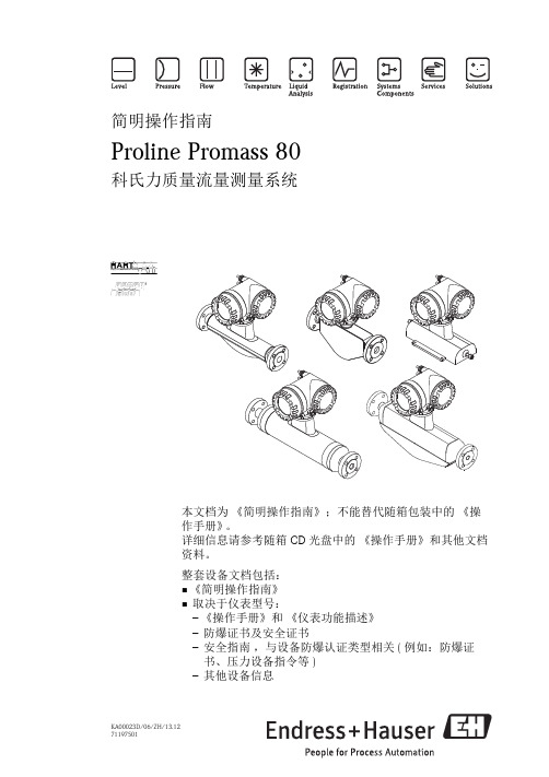
请勿通过变送器外壳或分体式仪表的传感器接线盒 起吊测量设备。请勿使用链条,链条可能损坏外 壳。
A0007409
2.2
安装条件
基于机械结构考虑,且为了保护管道,建议支撑大重量的传感器。 2.2.1 外形尺寸 测量设备的外形尺寸 请参考 《技术资料》 (CD 光盘中 )。 2.2.2 安装位置 建议在下列位置上安装: • 管件的上游管道,例如:阀门、三通、弯头等。 • 泵的带压侧 ( 高系统压力时 )。 • 上升管道的最低点 ( 高系统压力时 )。 避免在下列位置上安装: • 管道的最高点 ( 易积聚气体 )。 • 直接安装在向下排空管道的上方。需要在向下排空管道中使用测量设备时,请参考 《操作手册》 (CD 光盘中 )。
Endress+Hauser
5
安装
Proline Promass 80
2 安装 . . . . . . . . . . . . . . . . . . . . . . . . . . . . . . . . . . . . . . . . . . . . . . . 5
2.1 运输至测量点 . . . . . . . . . . . . . . . . . . . . . . . . . . . . . . . . . . . . . . . . . . . . . . . . . . . . . . . 5 2.2 安装条件 . . . . . . . . . . . . . . . . . . . . . . . . . . . . . . . . . . . . . . . . . . . . . . . . . . . . . . . . . . . 5 2.3 安装后操作 . . . . . . . . . . . . . . . . . . . . . . . . . . . . . . . . . . . . . . . . . . . . . . . . . . . . . . . . . 8 2.4 安装后检查 . . . . . . . . . . . . . . . . . . . . . . . . . . . . . . . . . . . . . . . . . . . . . . . . . . . . . . . . 11
泰特电子T800系列II辅助设备服务手册说明书
M800-001T800 Series IIAncillary EquipmentService ManualIssue 101May 1998M800-00-1012M800-00T800Head OfficeNew ZealandTait Electronics Ltd558 Wairakei RoadP.O. Box 1645ChristchurchNew ZealandPhone: 64 3 358-3399Fax: 64 3 358-3636Radio Systems Division535 Wairakei RoadP.O. Box 1645ChristchurchNew ZealandPhone: 64 3 358-3399Fax: 64 3 358-2825AustraliaTait Electronics (Aust) Pty Ltd 186 Granite StreetGeebung Qld 4034P.O. Box 679VirginiaQueensland 4014AustraliaPhone: 61 7 3865-7799Toll Free: 1800 077-112Fax: 61 7 3865-7990CanadaTait Mobile Radio Inc.Unit 5, 158 Anderson Avenue MarkhamOntario L6E1A9CanadaPhone: 1 905 472-1100Toll Free: 1 800 890-8248 Fax: 1 905 472-5300FranceTait France Sarl2 Avenue de la Cristallerie92 316 Sèvres, CedexFrancePhone: 33 1 41 14-05-50Fax: 33 1 41 14-05-55GermanyT ait Mobilfunk GmbHWillstätterstraße 50D-90449 Nürnberg 60GermanyPhone: 49 911 96 746-0Fax: 49 911 96 746-79Hong KongTait Mobile Radio (HK) LtdRoom 703ANew East Ocean Centre9, Science Museum RoadT sim Sha Tsui EastHong KongPhone: 852 2369-3040Fax: 852 2369-3009New ZealandT ait Communications LtdUnit 4, 75 Blenheim RoadP.O. Box 1185ChristchurchPhone: 64 3 348-3301Fax: 64 3 343-0558SingaporeTait Electronics (Far East) Pte Ltd4 Leng Kee RoadSIS Building #05-11ASingapore 159088Phone: 65 471-2688Fax: 65 479-7778T aiwanTait Electronics (T aiwan) Ltd1104, No. 142 Chung Hsiao E. RdSec. 4TaipeiTaiwanPhone: 886 2 731-1290Fax: 886 2 711-6351ThailandTait Mobile Radio Ltd14/1 Suwan TowerGround FloorSoi Saladaeng 1North Sathorn RoadBangrakBangkok 10500ThailandPhone: 662 267-6290-2Fax: 662 267-6293United KingdomTait Mobile Radio LtdErmine Business ParkErmine RoadHuntingdonCambridgeshire PE18 6Y AUnited KingdomPhone: 44 1480-52255Fax: 44 1480-411996USATait Electronics (USA) Inc.9434 Old Katy RoadSuite 110HoustonTexas 77055USAPhone: 1 713 984-8684Toll Free: 1 800 222-1255Fax: 1 713 468-6944M800-003About This ManualScope This manual contains general, technical and servicing informa-tion on T800 Series II ancillary equipment.FormatWe have published this manual in a ring binder so that "revision packages" containing additional information pertaining to new issues of PCBs, or to additional ancillary equipment, can be added as required.Revision PackagesRevision packages will normally be published when an ancillary equipment manual requires overhaul, or to coincide with the release of information on a new PCB, and may also contain addi-tions or corrections pertaining to other parts of the manual.If you return the address card at the front of this manual, you will be notified when revision packages containing new PCB information and/or text are available. You may then order as many packages as you require from your local Tait Company .Revision packages are supplied ready-punched for inclusion in your manual.Revision ControlEach page in this manual has a date of issue. This is to comply with various Quality Standards, but will also serve to identify which pages have been updated and when. Each page and its publication date is listed in the "List of Effective Pages", and a new list containing any new/revised pages and their publica-tion dates will be sent with each revision package.Any portion of text that has been changed is marked by a verti-cal line (as shown at left) in the outer margin of the page. Where the removal of an entire paragraph means there is no text left to mark, an arrow (as shown at left) will appear in the outer mar-gin. The number beside the arrow will indicate how many para-graphs have been deleted.The manual issue and revision status are indicated by the last three digits of the manual IPN. These digits start at 100 and will increment through 101, 102, 103, etc., as revision packages are published, e.g:Thus, Issue 103 indicates the third revision to issue 1 and means that three packages should have been added to the manual. The issue digit will only change if there is a major product revision,or if the number of revision packages to be included means that the manual becomes difficult to use, at which point a new issue manual will be published in a new ring binder.PCB InformationPCB information is provided for all current issue PCBs, as well as all previous issue PCBs manufactured in production quanti-ties, and is grouped according to PCB. Thus, you will find the21 0 3issue statusrevision status4M800-00parts list, grid reference index (if necessary), PCB layouts andcircuit diagram(s) for each individual PCB grouped together. Errors If you find an error in this manual, or have a suggestion on howit might be improved, please do not hesitate to contact the Tech-nical Writer, Tait Radio Systems Division, Tait Electronics Ltd,P.O. Box 1645, Christchurch, New Zealand.Technical InformationAny enquiries regarding this manual or the equipment it describes should be addressed in the first instance to your nearest approved Tait Dealer or Service Centre. Further technical assistance may be obtained from the Customer Support Group, Radio Systems Division, Tait Electronics Ltd, Christchurch, New Zealand.Updating Equipment And ManualsIn the interests of improving performance, reliability or servicing, Tait Electronics Ltd reserve the right to update their equipment and/or manuals without prior notice. CopyrightAll information contained in this manual is the property of Tait Electronics Ltd. All rights are reserved. This manual may not, in whole or part, be copied, photocopied, reproduced, translated stored or reduced to any electronic medium or machine readable form without prior written permission from Tait Electronics Ltd.Ordering Tait Service ManualsService Manuals should be ordered from your nearest Tait Branch or approved Dealer. When ordering, quote the Tait Internal Part Number (IPN) and, where applicable, the version.Date Of IssueIPN M800-00-101T800 Series II Ancillary Equipment Service ManualIssue 101 published April 1998M800-00 5 Table Of ContentsThis manual is divided into three parts as listed below, with each part being further sub-divided into sections. There is a detailed table of contents at the start of each part and/or section.Part TitleA General Servicing ProceduresB T807/808 Switching Power SupplyC T800-22-0000 Base Station/Repeater Rack Frame6M800-00 List Of Effective PagesThe total number of pages in this Manual is 195, as listed below.Page Issue Date Page Issue Date130/04/98230/04/98330/04/98430/04/98530/04/98630/04/98730/04/98830/04/98(blank) Part AI31/08/96II31/08/96(blank) 1.131/08/961.231/08/962.131/08/962.231/08/96(blank)3.131/08/963.231/08/964.131/08/964.231/08/96(blank)5.131/03/985.231/03/985.331/03/985.431/03/98(blank)6.131/08/966.231/08/96(blank) Part BI31/08/96II31/08/96(blank) 1.131/08/961.231/08/96(blank) 1.331/08/961.431/08/961.531/08/961.631/08/961.731/08/961.831/08/961.931/08/961.1031/08/96(blank)2.131/08/962.231/08/96(blank) 2.331/08/962.431/08/962.531/08/962.631/08/963.131/08/963.231/08/96(blank) 3.331/08/963.431/08/963.531/08/963.631/08/963.731/08/963.831/08/963.931/08/963.1031/08/96(blank)4.131/08/964.231/08/96(blank) 4.331/08/964.431/08/964.531/08/964.631/08/96(blank)5.131/08/965.231/08/96(blank) 5.331/08/965.431/08/966.131/08/966.231/08/96(blank) 6.331/08/966.431/08/966.531/08/966.631/08/966.731/08/966.831/08/966.931/08/966.1031/08/96(blank)M800-007 Page Issue Date Page Issue Date7.131/08/967.231/08/96(blank)7.331/08/967.431/08/967.531/08/967.631/08/967.731/08/967.831/08/968.1.131/08/968.1.231/08/96(blank)8.1.331/08/968.1.431/08/968.2.131/08/968.2.231/08/96(blank)8.2.331/08/968.2.431/08/968.2.531/08/96(blank)8.2.631/08/968.2.731/08/96 (fold-out)8.2.831/08/96(fold-out/blank) 8.2.931/08/968.2.1031/08/968.2.1131/08/96(blank)8.2.1231/08/968.2.1331/08/96(fold-out)8.2.1431/08/96(fold-out/blank) 8.2.1531/08/968.2.1631/08/968.2.1731/08/96(fold-out)8.2.1831/08/96(fold-out)8.2.1931/08/96(fold-out)8.2.2031/08/96 (fold-out/blank) 8.2.2131/08/968.2.2231/08/968.2.2331/08/968.2.2431/08/96(blank)8.2.2531/08/968.2.2631/08/968.2.2731/08/96(blank)8.2.2831/08/968.2.2931/08/96(fold-out)8.2.3031/08/96(fold-out/blank) 8.2.3131/08/968.2.3231/08/968.2.3331/08/96(blank)8.2.3431/08/968.2.3531/08/96(fold-out)8.2.3631/08/96(fold-out/blank) 8.2.3731/08/968.2.3831/08/968.2.3931/08/96(fold-out)8.2.4031/08/96(fold-out)8.2.4131/08/96(fold-out)8.2.4231/08/96(fold-out/blank) 8.2.4330/11/978.2.4431/08/968.2.4531/08/96(blank)8.2.4630/11/978.2.4731/08/96(fold-out)8.2.4831/08/96 (fold-blank)8.2.4930/11/978.2.5031/08/968.2.5131/08/96(blank)8.2.5231/08/968.2.5331/08/96(fold-out)8.2.5431/08/96(fold-out/blank) 8.2.5531/08/968.2.5631/08/968.2.5731/08/96(fold-out)8.2.5831/08/96(fold-out)8.2.5931/08/96(fold-out)8.2.6031/08/96(fold-out/blank) Part CI30/04/98II30/04/98(blank)1.130/04/981.230/04/98(blank)1.330/04/981.430/04/981.530/04/981.630/04/981.730/04/981.830/04/981.930/04/981.1030/04/982.130/04/982.230/04/98(blank)2.330/04/982.430/04/982.530/04/982.630/04/982.730/04/982.830/04/982.930/04/982.1030/04/98(blank)8M800-00 3.1.130/04/983.1.230/04/98(blank)3.1.330/04/983.1.430/04/98(blank)3.2.130/04/983.2.230/04/98(blank)3.2.330/04/983.2.430/04/983.2.530/04/983.2.630/04/983.2.730/04/983.2.830/04/983.2.930/04/983.2.1030/04/983.2.1130/04/98(fold-out)3.2.1230/04/98(fold-out)3.2.1330/04/98(fold-out)3.3.130/04/983.3.230/04/98 (blank)3.3.330/04/983.3.430/04/98 (blank)3.3.530/04/98(fold-out)3.3.630/04/98(fold-out)3.3.730/04/98(fold-out)3.3.830/04/983.3.930/04/983.3.1030/04/983.3.1130/04/983.3.1230/04/98(blank)M800-00 AI Part A General Servicing ProceduresThis part of the manual is divided into the sections listed below. These sections provide some general and advisory information on servicing procedures, a brief history of T800 programming software, and a list of Technical Instructions pertaining to T830 Series equipment.Section Title Page11.11.2GeneralCaution: CMOS DevicesCaution: Beryllium Oxide & Power Transistors1.11.11.222.12.2MechanicalPozidriv Recess Head ScrewsDisassembly/Reassembly2.12.12.133.13.1.13.1.23.2Component ReplacementLeaded ComponentsDesoldering Iron MethodComponent Cutting MethodSurface Mount Devices3.13.13.13.13.24 T o Remove Cased Mica Capacitors 4.155.15.25.35.4Software HistoryBASEPROG V1/PGM800 V2PGM800 V2.01PGM800 V2.21PGM800Win V1.005.15.15.15.25.26 T echnical Instructions 6.1Figure Title Page1.1 Typical Anti-static Bench Set-up 1.1AII M800-00M800-00General A1.11GeneralIf further information is required about any ancillary equipment or this Manual, it may be obtained from Tait Electronics Ltd or accredited agents. When requesting this infor-mation, please quote the equipment type number (e.g. T807-10) and serial number. In the case of the Service Manual quote the Tait Internal Part Number (IPN), e.g. M800-00-100, and for circuit diagrams quote the 'Title', 'IPN' and 'Issue'.1.1Caution: CMOS DevicesThis equipment contains CMOS Devices which are susceptible to damage from static charges. Care when handling these devices is essential. For correct handling proce-dures refer to the manufacturers' data books, e.g. Philips data books covering CMOS devices, or Motorola CMOS data books, Section 5 'Handling', etc.Figure 1.1 Typical Antistatic Bench Set UpAn antistatic bench kit (refer to Figure 1.1) is available from Tait Electronics Ltd under the usual consumable goods ordering system. The kit is held in stock under IPN 937-00000-34 and contains:• 1 conductive rubber bench mat• 1 earth lead to connect the mat to ground (c/w 1M series resistor)• 1 wrist strap•information leaflet.conductive rubber bench matmetal frameto building earth(not mains earth)via 1M series resistor conductivewrist strapA1.2General M800-00 1.2Caution: Beryllium Oxide & Power TransistorsThe power transistors in current use all contain some beryllium oxide. This substance, while perfectly harmless in its normal solid form, can become a severe health hazard when it has been reduced to dust. For this reason the power transistors should not be broken open, mutilated, filed, machined, or physically damaged in any way that can produce dust particles.M800-00Mechanical A2.1 2Mechanical2.1Pozidriv Recess Head ScrewsPozidriv recess head screws are the preferred standard on all Tait manufactured equip-ment. The very real advantages of this type of screw will not be realised unless the cor-rect screwdrivers are used by servicing personnel.2.2Disassembly/ReassemblyInstructions on disassembly/reassembly for individual equipment are given in the rele-vant part of this manual.A2.2Mechanical M800-00M800-00Component Replacement A3.1 3Component Replacement3.1Leaded ComponentsWhenever components are removed from or fitted to a PCB, care must be taken to avoid damage to the track. The two satisfactory methods of removing components from PTH PCBs are detailed below.Note:The first method requires the use of a desoldering station, e.g. Philips SBC 314 or Pace MBT-100E.3.1.1Desoldering Iron MethodPlace the tip over the lead and, as the solder starts to melt, move the tip in a circu-lar motion.Start the suction and continue the movement until 3 or 4 circles have been com-pleted.Remove the tip while continuing suction to ensure that all solder is removed from the joint, then stop the suction.Before pulling the lead out, ensure it is not stuck to the plating.If the lead is still not free, resolder the joint and try again.Note:The desoldering iron does not usually have enough heat to desolder leads from the ground plane. Additional heat may be applied by holding a sol-dering iron on the tip of the desoldering iron (this may require some addi-tional help).3.1.2Component Cutting MethodCut the leads on the component side of the PCB.Heat the solder joint sufficiently to allow easy removal of the lead by drawing it out from the component side: do not use undue force.Fill the hole with solder and then clear with solderwick.A3.2Component Replacement M800-00 3.2Surface Mount DevicesCaution:Surface mount devices (SMDs) require special storage, handling,removal and replacement techniques. This equipment should be serv-iced only by an approved T ait Dealer or Service Centre equipped withthe necessary facilities. Repairs attempted with incorrect equipment orby untrained personnel may result in permanent damage. If in doubt,contact T ait Electronics Ltd or your nearest T ait Branch or Subsidiary.M800-00To Remove Cased Mica Capacitors A4.1 4To Remove Cased Mica CapacitorsCased mica capacitors can be removed by heating the top with a heavy-duty soldering iron and gently lifting the capacitor off the PCB with a solder-resistant spike or equiva-lent.A4.2To Remove Cased Mica Capacitors M800-00M800-00Software History A5.1 5Software History23/11/89BASEPROG V ersion 123/08/90PGM800 V ersion 211/06/91PGM800 V ersion 2.0103/10/95PGM800 V ersion 2.2128/06/96PGM800Win V ersion 1.0018/08/97PGM800Win V ersion 2.005.1BASEPROG V1/PGM800 V2T800 programming software was originally developed as BASEPROG V1 and released as PGM800 V2.5.2PGM800 V2.01The major changes introduced with V2.01 are as follows:•Full support for different display adaptors.•Programming of CTCSS frequency data (optional) for individual channels.•Full cursor control in edit mode.•User selectable output file format (hex or binary).•Support for wider range of T800 equipment.•DOS shell facility implemented.•CTCSS defeat possible when CTCSS tone is not selected.•Channel numbering changed from 0-127 to 1-128.•An "X" included on the printout to indicate that there are 8 switches on the DIP switch and the state of the MSB is dependent on the size of the EPROM used. Note:The data files produced by BASEPROG V1.0 are still compatible with PGM800 V2.01.A5.2Software History M800-00 5.3PGM800 V2.21PGM800 V2.21 is an updated and expanded version of the earlier PGM800 V2.01 soft-ware.PGM800 V2.21 includes many new and improved features over PGM800 V2.01. There are a number of changes to the user interface to make data entry and editing signifi-cantly easier.Major changes are outlined below:•Includes several new radio models which are not programmable with PGM800 V2.01.•Default file names with ‘dash’ are saved with ‘dash’ instead of ‘underscore’.•Default file extension in Save File page is BIN instead of HEX.•Out of range frequencies will result in warning messages, but will still be accepted as valid entries.•Channel numbers are selectable between 0-127 and 1-128.•Automatic insertion feature to input frequencies.Note:The datafiles produced by BASEPROG V1.0 and PGM800 V2.01 are still compatible with PGM800 V2.21.5.4PGM800Win V1.00PGM800Win V1.00 is different in concept from DOS versions of PGM800 in that it is Windows TM driven. It includes many new and improved features over DOS versions of PGM800.Major changes are outlined below:•The Windows environment makes data entry and editing significantly easier.•Includes several new radio models which are not programmable with DOS ver-sions of PGM800.•Out of range frequencies will result in warning messages and will not be accepted for entry into the standard library module. User defined modules can be created allowing variation from the standard library module.•Channel numbers default to 0-127 to match the EPROM memory locations, how-ever the user can change the setting so that the channel numbers run from 1-128 to suit his/her particular needs.M800-00Software History A5.3 Note:The datafiles produced by BASEPROG V1.0 and all DOS versions PGM800 are still compatible with PGM800Win V1.00.5.5PGM800Win v2.00PGM800Win V2.00 is an upgraded and expanded version of PGM800Win V1.0. It has been developed specifically for T800 Series II base stations but also has the capability of programming Series I equipment.Major changes are outlined below:•The Windows environment makes data entry and editing significantly easier. •Includes several new radio models which are not programmable with DOS ver-sions of PGM800.•Out of range frequencies will result in warning messages and will not be accepted for entry into the standard library module. User defined modules can be created, allowing variation from the standard library module.•Channel numbers default to 0-127 to match the EPROM memory locations, how-ever the user can change this setting so that the channel numbers run from 1-128 to suit his/her particular needs.•The ability to program T800 Series II base station modules via serial communica-tions.•Deviation and reference modulation settings are written automatically to the radio.•Extra information that is not stored in the radio (but is information relevant to the radio) can be saved to a file on disk (e.g. note field, auxilliary pin names etc). Note:The datafiles produced by BASEPROG V1.0. all DOS versions of PGM800 and PGM800Win V1.0 are still compatible with PGM800Win V2.00.A5.4Software History M800-00M800-00Technical Instructions A6.1 6Technical InstructionsFrom time to time Technical Instructions (TIs) are issued by the Radio Infrastructure Engineering Division of Tait Electronics. These TIs may be used to update equipment or information, or to meet specific operational requirements.TIs applicable to specific T800 Series ancillary equipment are listed in the relevant part of this manual.A6.2Technical Instructions M800-00。
百得说明书IBR

Declaration of Conformity
We declare that our products BPM...; BGN…; BT…; BTG…; BTL…; TBML...; Comist…; GI…; GI…Mist; Minicomist…; PYR…; RiNOx…; Spark...; Sparkgas...; TBG...;TBL...; TS…; IBR...; IB... (Variant: … LX, for low NOx emissions) Description: forced air burners of liquid, gaseous and mixed fuels for residential and industrial use meet the minimum requirements of the European Directives: 90/396/CEE ...............................................(D.A.G.) 89/336/CEE - 2004/108/CE ........................(C.E.M.) 73/23/CEE – 2006/95/CE ...........................(D.B.T.) 2006/42/CEE .............................................(D.M.) and conform to European Standards: UNI EN 676:2008 (gas and combination, gas side) UNI EN 267:2002 (diesel and combination, diesel side) These products are therefore marked:
瑞士万通离子色谱仪800 Dosino进样器说明书--英文
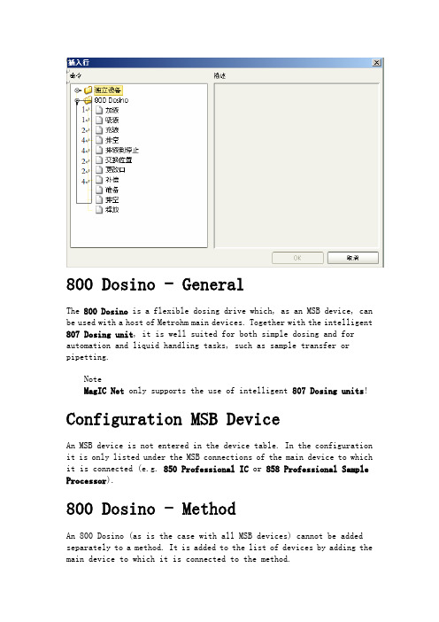
800 Dosino - GeneralThe 800 Dosino is a flexible dosing drive which, as an MSB device, can be used with a host of Metrohm main devices. Together with the intelligent 807 Dosing unit, it is well suited for both simple dosing and for automation and liquid handling tasks, such as sample transfer or pipetting.NoteMagIC Net only supports the use of intelligent 807 Dosing units! Configuration MSB DeviceAn MSB device is not entered in the device table. In the configuration it is only listed under the MSB connections of the main device to which it is connected (e.g. 850 Professional IC or 858 Professional Sample Processor).800 Dosino - MethodAn 800 Dosino (as is the case with all MSB devices) cannot be added separately to a method. It is added to the list of devices by adding the main device to which it is connected to the method.If the method is created without connected devices, the MSB device can be added separately. In this case, the MSB connector on the main device must be entered manually.In the device group, the 800 Dosino behaves like a stand-alone device. It can be selected and displayed graphically in the upper area of the device window.800 Dosino - Start parametersTab: Method ▶ Devices ▶ DosinoSolutionSelect the solution for the Dosino that should be available when the hardware is started with [Start HW]. A check is carried out in the method run to ensure that the correct solution has been put on the dosing device. When the method is started, the working life and GLP test interval are checked for the selected solution.Selection not defined | Solutions from the solution tableDefault value not definednot definedThe solution is not checked.Solutions from the solution tableOnly "intelligent" solutions, i.e. solutions that are assigned to an 807 Dosing unit, can be selected.ConnectorShows the main device and the MSB connector which the 800 Dosino is on.800 Dosino - CommandsOverview of the time program commands available for the 800 Dosino:DosingDialog window: Method ▶Time program ▶Edit ▶'Device' - DosingThe device-dependent time program command Dosing (command with feedback) doses the specified volume via the defined port. There is no automatic filling beforehand or afterwards.ParametersPortPort via which dosing takes place. Formula input possible.Range 1 (4)Default value 1V olumeVolume to be transported. Formula input possible.Range0.0000 ... 99999.9000 mLDefault value 1.0000 mLDosing rateSpeed at which discharge takes place. The maximum rate depends on the cylinder volume of the buret used. Formula input possible.Cylinder volume 2 mLRange0.01 ... 6.00 mL/minDefault value 1.00 mL/minSelection maximumCylinder volume 5 mLRange0.01 ... 16.00 mL/minDefault value 1.00 mL/minSelection maximumCylinder volume 10 mLRange0.01 ... 33.00 mL/minDefault value 1.00 mL/minSelection maximumCylinder volume 20 mLRange0.01 ... 66.00 mL/minDefault value 1.00 mL/minSelection maximumCylinder volume 50 mLRange0.01 ... 166.00 mL/minDefault value 1.00 mL/minSelection maximumFilling rateSpeed at which filling takes place. The maximum rate depends on the cylinder volume of the buret used. Formula input possible.Cylinder volume 2 mLRange0.01 ... 6.00 mL/minDefault value 1.00 mL/minSelection maximumCylinder volume 5 mLRange0.01 ... 16.00 mL/minDefault value 1.00 mL/minSelection maximumCylinder volume 10 mLRange0.01 ... 33.00 mL/minDefault value 1.00 mL/minSelection maximumCylinder volume 20 mLRange0.01 ... 66.00 mL/minDefault value 1.00 mL/minSelection maximumCylinder volume 50 mLRange0.01 ... 166.00 mL/minDefault value 1.00 mL/minSelection maximumCommentOptional comment on the time program command.Input64 charactersGenerated variablesThe following type 'mand number.Variable name' variables are generated by the command:AspirateDialog window: Method ▶Time program ▶Edit ▶'Device' - AspirateThe device-dependent time program command Aspirate (command with feedback) draws in the specified volume via the defined port. As with the command Dosing, the cylinder is not filled automatically beforehand or afterwards. It should be possible to achieve the volume to be aspirated with a single piston stroke.ParametersPortPort via which aspiration takes place. Formula input possible.Range 1 (4)Default value 1V olumeVolume to be transported. Formula input possible.Range0.0000 ... 50.0000 mLDefault value 1.0000 mLRateThe maximum rate depends on the cylinder volume of the buret used. Formula input possible.Cylinder volume 2 mLRange0.01 ... 6.00 mL/minSelection maximumDefault value maximumCylinder volume 5 mLRange0.01 ... 16.00 mL/minSelection maximumDefault value maximumCylinder volume 10 mLRange0.01 ... 33.00 mL/minSelection maximumDefault value maximumCylinder volume 20 mLRange0.01 ... 66.00 mL/minSelection maximumDefault value maximumCylinder volume 50 mLRange0.01 ... 166.00 mL/minSelection maximumDefault value maximumCommentOptional comment on the time program command.Input64 charactersGenerated variablesThe following type 'mand number.Variable name' variables are generated by the command:FillDialog window: Method ▶Time program ▶Edit ▶'Device' - FillThe device-dependent time program command Fill (command with feedback) fills the cylinder via the specified port. The valve disc stops on the selected port.ParametersPortPort via which filling takes place. Formula input possible.Range 1 (4)Default value 2RateThe maximum rate depends on the cylinder volume of the buret used. Formula input possible.Cylinder volume 2 mLRange0.01 ... 6.00 mL/minSelection maximumDefault value maximumCylinder volume 5 mLRange0.01 ... 16.00 mL/minSelection maximumDefault value maximumCylinder volume 10 mLRange0.01 ... 33.00 mL/minSelection maximumDefault value maximumCylinder volume 20 mLRange0.01 ... 66.00 mL/minSelection maximumDefault value maximumCylinder volume 50 mLRange0.01 ... 166.00 mL/minSelection maximumDefault value maximumCommentOptional comment on the time program command.Input64 charactersEject to end volumeDialog window: Method ▶Time program ▶Edit ▶'Device' - Eject to end volumeThe device-dependent time program command Eject to end volume (command with feedback) ejects the entire contents of the cylinder via the specified port. In contrast to the command Eject to stop, the piston travels to the maximum volume mark i.e. until it has performed 10,000 pulses. This command should be used for pipetting functions for emptying the cylinder.ParametersPortPort via which ejection takes place. Formula input possible.Range 1 (4)Default value 4RateThe maximum rate depends on the cylinder volume of the buret used. Formula input possible.Cylinder volume 2 mLRange0.01 ... 6.00 mL/minSelection maximumDefault value maximumCylinder volume 5 mLRange0.01 ... 16.00 mL/minSelection maximumDefault value maximumCylinder volume 10 mLRange0.01 ... 33.00 mL/minSelection maximumDefault value maximumCylinder volume 20 mLRange0.01 ... 66.00 mL/minSelection maximumDefault value maximumCylinder volume 50 mLRange0.01 ... 166.00 mL/minSelection maximumDefault value maximumCommentOptional comment on the time program command.Input64 charactersEject to stopDialog window: Method ▶Time program ▶Edit ▶'Device' - Eject to stopThe device-dependent time program command Eject to stop (command with feedback) ejects the entire contents of the cylinder via the specified port. The piston is lowered to the stop point, i.e. past the maximum volume mark.NoteThis function should only be carried out to eject any air bubbles present.CautionThe command aspirate does not function directly after Eject to stop.If aspiration is to take place after Eject to stop, then Eject to end volume must first be carried out. In this command, the port via which aspiration is to take place must already be selected.ParametersPortPort via which ejection takes place. Formula input possible.Range 1 (4)Default value 4RateThe maximum rate depends on the cylinder volume of the buret used. Formula input possible.Cylinder volume 2 mLRange0.01 ... 6.00 mL/minSelection maximumDefault value maximumCylinder volume 5 mLRange0.01 ... 16.00 mL/minSelection maximumDefault value maximumCylinder volume 10 mLRange0.01 ... 33.00 mL/minSelection maximumDefault value maximumCylinder volume 20 mLRange0.01 ... 66.00 mL/minSelection maximumDefault value maximumCylinder volume 50 mLRange0.01 ... 166.00 mL/minSelection maximumDefault value maximumCommentOptional comment on the time program command.Input64 charactersExchange positionDialog window: Method ▶Time program ▶Edit ▶'Device' - Exchange positionWith the device-dependent time program command Exchange position (command with feedback) the cylinder is first filled via the port specified. The valve disc is then turned to Port 2 and the dosing unit can be removed from the dosing drive.ParametersFill portPort via which filling takes place. Formula input possible.Range 1 (4)Default value 2RateThe maximum rate depends on the cylinder volume of the buret used. Formula input possible.Cylinder volume 2 mLRange0.01 ... 6.00 mL/minSelection maximumDefault value maximumCylinder volume 5 mLRange0.01 ... 16.00 mL/minSelection maximumDefault value maximumCylinder volume 10 mLRange0.01 ... 33.00 mL/minSelection maximumDefault value maximumCylinder volume 20 mLRange0.01 ... 66.00 mL/minSelection maximumDefault value maximumCylinder volume 50 mLRange0.01 ... 166.00 mL/minSelection maximumDefault value maximumCommentOptional comment on the time program command.Input64 charactersChange portDialog window: Method ▶Time program ▶Edit ▶'Device' - Change portThe device-dependent time program command Change port (command with feedback) results only in one rotation of the valve to the given port and not in any piston movement.ParametersPortPort to which the valve is rotated. Formula input possible.Range 1 (4)Default value 2CommentOptional comment on the time program command.Input64 charactersCompensateDialog window: Method ▶Time program ▶Edit ▶'Device' - CompensateBecause of the fact that the dosing units are interchangeable, the coupling of the Dosino piston rod (spindle) exhibits a low mechanical tolerance that can be noticed when the piston changes its direction of movement. This tolerance can be compensated for with the device-dependent time program command Compensate (command with feedback). A short piston movement is first made in the same direction as the previous movement, which is then followed by a piston movement in the reverse direction.ParametersPortPort via which the piston motion runs. Formula input possible.Range 1 (4)Default value 4CommentOptional comment on the time program command.Input64 charactersPrepareDialog window: Method ▶Time program ▶Edit ▶'Device' - PrepareThe device-dependent time program command Prepare (command with feedback) is used to prepare a dosing unit.The cylinder and all the tubing of a dosing unit are rinsed in an extensive cleaning sequence. The parameters required for this process are stored in the configuration of the solution.CommentOptional comment on the time program command.Input64 charactersEmptyDialog window: Method ▶Time program ▶Edit ▶'Device' - EmptyThe device-dependent time program command Empty (command with feedback) is used to empty the cylinder and the tubing of a dosing unit.The cylinder and all the tubing of a dosing unit are emptied in an extensive sequence. The parameters required for this process are stored in the configuration of the solution.CommentOptional comment on the time program command.Input64 charactersReleaseDialog window: Method ▶Time program ▶Edit ▶'Device' - 'Module' - ReleaseThe device-dependent time program command Release (command without feedback) releases the module/device for use by other methods running at the same time. It removes the reservation made by the current method.TimeTime at which the command is to be executed.Range0.00 ... 10000.00 minIncrement0.01 minDefault value0.00 minCommentOptional comment on the time program command.Input0 ... 64 characters800 Dosino - Manual ControlTab: Manual ▶Manual Control - 'Device name' ▶'Dosino'CommandSelection of the Dosino command that is to be triggered manually.Selection Dosing | Aspirate | Fill | Prepare | EmptyDefault value DosingDosingDoses the specified volume via the defined port. There is no automatic filling beforehand or afterwards.AspirateAspirates the specified volume via the defined port. There is no automatic filling beforehand or afterwards.FillThe cylinder is filled in a fixed sequence. The parameters required for this process are stored in the configuration of the solution.PrepareThe cylinder and all the tubing of a dosing unit are rinsed in an extensive cleaning sequence. The parameters required for this process are stored in the configuration of the solution.EmptyThe cylinder and all the tubing of a dosing unit are emptied in an extensive sequence. The parameters required for this process are stored in the configuration of the solution.SolutionDisplays the solution assigned to the Dosino.VolumeCurrent valueDisplays the current dosed volume.InputEnter the volume that is to be dosed / moved.Range0.0000 ... 99999.9000 (Exception: with command "Aspirate" 50.0000) mL Default value 1.0000 mLPortCurrent valueShows the current port.InputSelection of a port for the action selected in the parameter Command.Range 1 (4)Default value 1Dosing rateInputEnter dosing rate. The maximum rate depends on the cylinder volume of the buret used. Formula input possible.Cylinder volume 2 mLRange0.01 ... 6.00 mL/minSelection maximumDefault value maximumCylinder volume 5 mLRange0.01 ... 16.00 mL/minSelection maximumDefault value maximumCylinder volume 10 mLRange0.01 ... 33.00 mL/minSelection maximumDefault value maximumCylinder volume 20 mLRange0.01 ... 66.00 mL/minSelection maximumDefault value maximumCylinder volume 50 mLRange0.01 ... 166.00 mL/minSelection maximumDefault value maximumFilling rateInputEnter filling rate. The maximum rate depends on the cylinder volume of the buret used. Formula input possible.Cylinder volume 2 mLRange0.01 ... 6.00 mL/minSelection maximumDefault value maximumCylinder volume 5 mL Range0.01 ... 16.00 mL/minSelection maximumDefault value maximumCylinder volume 10 mL Range0.01 ... 33.00 mL/minSelection maximumDefault value maximumCylinder volume 20 mL Range0.01 ... 66.00 mL/minSelection maximumDefault value maximumCylinder volume 50 mL Range0.01 ... 166.00 mL/minSelection maximumDefault value maximum[Start]Start Dosino command.[Stop]Stop Dosino command.。
瀚斯宝丽使用说明
第 3 章:输入文本 . . . . . . . . . . . . . . . . . . . . . . . . . . . . . . . . . . . . 18
文本输入方法 . . . . . . . . . . . . . . . . . . . . . . . . . . . . . . . . . . . . . . . 18 使用 (QWERTY) 键盘输入文本 . . . . . . . . . . . . . . . . . . . . . . . . . . 18 使用符号 / 数字模式 . . . . . . . . . . . . . . . . . . . . . . . . . . . . . . . . . . 18 . . . . . . . . . . . . . . . . . . . . . . . . . . . . . . . . . . . . 27
硬件连接 . . . . . . . . . . . . . . . . . . . . . . . . . . . . . . . . . . . . . . . . . . . 电脑连接 . . . . . . . . . . . . . . . . . . . . . . . . . . . . . . . . . . . . . . . . 存储卡 . . . . . . . . . . . . . . . . . . . . . . . . . . . . . . . . . . . . . . . . . . 附件连接 . . . . . . . . . . . . . . . . . . . . . . . . . . . . . . . . . . . . . . . . 软件连接 . . . . . . . . . . . . . . . . . . . . . . . . . . . . . . . . . . . . . . . . . . . 浏览器 . . . . . . . . . . . . . . . . . . . . . . . . . . . . . . . . . . . . . . . . . . Wi-Fi . . . . . . . . . . . . . . . . . . . . . . . . . . . . . . . . . . . . . . . . . . . 蓝牙 . . . . . . . . . . . . . . . . . . . . . . . . . . . . . . . . . . . . . . . . . . . . 虚拟专用网 (VPN) . . . . . . . . . . . . . . . . . . . . . . . . . . . . . . . . . 27 27 27 28 29 29 30 30 30
布加斯电子产品说明书

The 18" wide dishwasher perfectly fits in compact spaces.
Features & Benefits
46 dBA: dishwasher runs quietly so your kitchen conversations aren’t interrupted.
Notes: All height, width and depth dimensions are shown in inches. BSH reserves the absolute and unrestricted right to change product materials and specifications, at any time, without notice. Consult the product’s installation instructions for final dimensional data and other details prior to making cutout.
2 1/2" (63.5 mm)
Junction box accessory available for purchase SMZPCJB1UC (not included)
Example of Hardwire Installation
Ø 2 1/2" (63.5 mm)
7" (178 mm)
Note: Cutout required on left or right cabinet wall, depending on location of water inlet, drain and electrical connection
2-S8000监测分站使用手册
S8000工厂监测诊断平台工厂监测诊断平台 ――――适用于适用于PWR8000/NET8000振动监测监测分站使用手册阿尔斯通创为实技术发展阿尔斯通创为实技术发展((深圳深圳))有限公司Version 3.42 2008.10目录第一章 介 绍 (2)第二章 指示灯 (5)第三章 安装与接线 (7)第四章 故障排除 (14)第五章IP设置及软件使用 (17)第六章MODBUS的调试 (22)第七章 附录 (26)第一章介绍监测分站系统是S8000大型旋转机械在线状态监测和分析系统的组成部分之一,主要任务是完成大型机组振动信号与过程信号的数据采集、分析及网络接口功能,通常安装在机组的主控室里。
本产品可以通过工厂内局域网络与WEB8000服务器、浏览分站构成一个完整的在线状态监测与分析系统,也可以采用最简模式通过网线与一台浏览分站自成体系。
监测分站系统根据应用的行业不同分为NET8000、PWR8000和HYD8000等系列,分别对应石化和冶金、电力、水电等行业。
根据处理的信号通道能力不同还可细分为Plus和Dual系列,其中Plus系列可最多接入4个键相信号、24个振动信号和12个轴位移或过程量信号;Dual系列可最多接入8个键相信号、48个振动信号和24个轴位移或过程量信号;其外形大小尺寸一致,安装和维护方式相同。
监测分站系统由主机、50芯专用电缆与接线端子板构成。
现场机组的键相信号、振动信号与过程信号从现场有关二次仪表的相应端口引出接到接线端子板上,根据不同的信号特点相应调整端子板上的跳线开关,再由端子板上DB50口插座通过50芯电缆与监测分站主机相连。
1.1 监测分站主机图1-1 NET8000 Dual主机(示例)监测分站主机是最新一代全集成、一体化(ALL-IN-ONE)的现场监测分析站。
集成了设备监测、故障诊断、数据采集、信号分析、计算机、网络通信等各个领域的先进技术,代表了新一代在线状态监测系统的发展方向。
AyersGTS 使用手冊说明书

AyersGTS工作站使用手冊Ayers Solutions Limited修改紀錄版本日期詳情copyV1.0 22-Mar-04 InitialV1.1 25-Mar-04 Update the section “Recommended Daily Operation Flow”V1.2 18-Apr-04 Update the “Input Order” sectionUpdate the “Upload Interface File” sectionUpdate the “Client Master” screenAdd section “Enable Internet Trading For Client Acc”V1.4.5 13-Jul-04 Update the “Input Order” SectionV1.4.12 20-Jan-05 Update the “save/load/clear desktop setting” SectionAdd “Report” sectionV1.5 15-Mar-05 Add the “Enable IVR trading” sectionAdd the “Filter rows in order journal” sectionAdd the “Update/Cancel multiple orders” sectionAdd section “Sell Transaction Amount Limit”V1.6.4 13-Mar-06 Update with latest information up to v1.6.4graphicstheV1.6.6 22-May-06 UpdateV1.6.8 28-Aug-06 Add new credit line “Nominal Deviation Limit” on Appendix AV1.6.8a 30-Nov-06 Add the “Run Batch Report” SectionV1.7.6 10-Oct-07 User manual revampV1.8.2 18-June-08 User manual revampV1.8.3 1-Aug-08 Add Manual Trade and Odd Lot Trade sectionV1.8.3 4-Aug-08 Add enhanced stop limit order with trailing stop sectionV1.9.0 17-Nov-08 Add Futures functionV1.9.3 22-Jun-09 User manual revampV1.10.0 8-Feb-10 User manual revampV1.10.3 26-June-10 User manual revampV1.10.4 8-Jul-10 Add “Last Updated Time” in “O/S Order” and “Today Orders” pageof Client Portfolio EnquiryAdd Reject Confirmed Cash Deposit/WithdrawCan disable the client a/c field input in Client PortfolioV1.10.5 13-Aug-10 Able to lock/unlock windows ; Group the windows in GTSAdd the URL access right in Market InformationAble to remove the button “Cancel All” and “Close All Positions” inGlobal Market Layout 2; Able to show column ‘Condition’ (OrderType + Condition) in Order JournalV1.10.6 22-Oct-10 Batch Interface File Import/Export SchedulerNew fields (e.g. Trigger price, fee, exchange order info) availablein Order Journal ;Show average price in Client Portfolio and Client Product PositionV1.10.7 26-Nov-10 Allow to copy/duplicate report job item;Allow to send email for report jobV1.10.8 28-Dec-10 New Function : User Reset PasswordV1.11.0 15-Jan-11 User manual revampV1.11.1 19-Feb-11 Request add “currency” column in order journal and trade journalAdd margin calculation mode in Setup ExchangeV1.11.2 18-June-11 User manual revampV1.11.3 23-Aug-11 User manual revampV1.11.4 18-Jun-11 User manual revampV1.11.5 21-Jul-11 User manual revampV1.11.6 2-Sep-11 User manual revampV1.11.7 1-Feb-11 User manual revampV1.12.1 10-Mar-12 User manual revampV1.12.4 14-Sept-12 User Manual revampV1.13.1 12-April-12 User Manual revampV1.13.5 30-May-14 User Manual revampV1.13.6 18-Dec-15 User Manual revampV1.13.7 15-Feb-16 User Manual revampV1.13.8 20-Jul-18 Cyber Security目錄1. 序 (10)2. 關於AyersGTS (12)3. 關於AyersGTS Lite (12)4. 開始使用☆ (13)4.1 登入☆ (13)4.2 更改密碼☆ (13)4.3 登出☆ (14)5. 使用介面☆ (15)5.1 主視窗☆ (15)5.2 常用圖示☆ (15)5.3 時鐘☆ (16)5.4 螢幕鎖☆ (16)5.5 載入桌面設定☆ (17)5.6 儲存桌面設定☆ (17)5.7 清除桌面設定☆ (18)5.8 查詢已開啟的版面☆ (18)5.9 傳送今日消息(網上客戶) (19)5.10 傳送今日消息 (20)5.11 顯示今日消息☆ (20)5.12 傳送電郵 (21)5.13 強迫使用者登出 (21)5.14 更改用戶設定 (23)5.15 客戶快捷鍵設定☆ (27)5.16 客戶群組快捷鍵設定 (29)5.17 客戶下單群組快捷鍵設定 (29)5.18 經記行即時報價顏色 (30)5.19 鎖定視窗位置及大小☆ (33)5.20 視窗群組☆ (34)5.21 放大/縮小視窗☆ (35)5.22 用戶/客戶主任/客戶戶口快速搜尋模式 (36)5.23 選擇字體顏色☆ (37)5.24 選擇背景顏色☆ (37)6. 系統設定 (38)6.1 設定系統參數 (38)6.1.1 設定 1 (38)6.1.2 設定 2 (39)6.1.3 設定 3 (42)6.1.4 設定 4 (42)6.1.5 設定5 (44)6.1.6 設定6 (44)6.2 密碼規格 (46)6.3 設定貨幣 (49)6.4 銀行 (49)6.5 交易限額政策 (50)6.6 批核級別 (51)6.7 用戶群組 (53)6.8.2 用戶群組 (57)6.8.3 用戶權限 (58)6.8.4 備註 (59)6.8.5 可管理客戶戶口 (60)6.8.6 交易限額 (61)6.8.7 設定 (62)6.8.8 快捷鍵 (63)6.8.9 交易所 (65)6.9 重設用戶密碼 (66)6.10 用戶(LITE網上用戶) (67)6.11 客戶主任群組 (68)6.12 客戶主任 (68)6.13 客戶戶口類別 (68)6.13.1 給客戶類別設置交易限額及信貸比率 (69)6.14 客戶群組 (70)6.15 客戶下單群組 (71)6.15.1 建立客戶下單群組 (72)6.15.2 分配客戶到特定下單群組 (73)6.15.3 客戶下單群組快捷鍵設定 (74)6.16 客戶戶口 (75)6.16.1 客戶通知訊息 (75)6.16.2 網上客戶使用即時報價服務 (78)6.16.3 使用音頻電話交易服務 (79)6.16.4 設置客戶交易限額及信貸比率 (80)6.16.5 設置客戶佣金率 (81)6.16.6 人證港幣交易通 (82)6.16.7 拒絕客戶買入 / 沽出指定產品 (84)6.16.8 待跟進記錄 (86)6.17 交易所 (91)6.17.1 啟用/停用訂單類型 (95)6.18 交易產品群組 (98)6.19 產品資料 (99)6.19.1 按揭級別 (101)6.20 訂單路由群組 (103)6.21 訂單路由 (105)6.22 關連產品 (105)6.23 認購新股 (IPO) (107)6.23.1 資料 (107)6.23.2 數量 / 金額表 (109)6.23.3 申請 (111)6.23.4 電郵傳送認購結果 (114)6.24 報表工作項目 (117)6.25 多檔案匯入 / 匯出 (120)6.25.1 多檔案匯入 / 匯出- 匯入 (120)6.25.2 多檔案匯入 / 匯出 - 匯出 (122)6.26 多檔案匯入 / 匯出自動執行-匯入 (123)6.26.1 多檔案匯入 / 匯出自動執行- 匯出 (124)7.1.2 設定訂單資料夾☆ (127)7.1.3 篩選訂單資料夾訂單☆ (129)7.1.4 查詢訂單資料☆ (130)7.1.5 使用訂單功能表☆ (131)7.1.6 更改訂單☆ (132)7.1.7 取消訂單☆ (133)7.1.8 更改 / 取消多筆訂單☆ (134)7.1.9 新增 / 移除欄位☆ (136)7.2 交易成交資料夾☆ (140)7.3 成交量查詢 (143)7.4 追收保證金客戶資料夾 (143)7.5 追收保證金客戶資料夾(單一貨幣計算) (146)7.6 輸入訂單☆ (146)7.6.1 使用輸入訂單畫面 (證券市場) ☆ (146)7.6.2 使用輸入訂單畫面 (環球市場) ☆ (160)7.6.3 輸入訂單 (環球市場, 只限買入)☆ (161)7.6.4 程式買賣 (香港交易所-股票) ☆ (167)7.7 買賣數量選擇器☆ (176)7.8 使用訂單快捷鍵☆ (177)7.9 輸入已成交訂單 (179)7.10 輸入新股認購 (180)7.11 輸入新股認購(網上用戶) (181)7.12 輸入新股認購(版面一) (181)7.13 查詢訂單 (184)7.14 客戶戶口資料☆ (185)7.14.1 產品結存 ☆ (185)7.14.2 待成交訂單☆ (186)7.14.3 新增 / 移除欄位☆ (186)7.14.4 篩選訂單☆ (190)7.14.5 今日訂單☆ (191)7.14.6 新增 / 移除欄位☆ (194)7.14.7 篩選訂單☆ (197)7.14.8 今日成交☆ (198)7.14.9 資料☆ (198)7.14.10 交易分配☆ (199)7.14.11 待跟進記錄☆ (200)7.14.12 新股認購 (201)7.15 客戶下單群組戶口資料 (201)7.16 客戶產品持貨查詢 (203)7.17 客戶盈虧查詢 (203)7.18 產品持貨總覽 (204)8.1 訂單批核資料夾 (205)8.2 客戶現金存款或提款 (207)8.3 客戶支票存款 (207)8.4 客戶現金存款或提款(小額) (208)8.5 批核客戶現金存款或提款 (208)8.6 批核客戶現金存款 (208)8.8 批核客戶現金提款 (209)8.9 上傳多筆客戶現金存款或提款 (210)8.10 拒絕已批核客戶現金存/提款 (210)8.11 客戶外幣轉換 (212)8.12 客戶現貨存入或提走 (213)8.13 上傳多筆客戶現貨存入或提走 (213)8.14 批核客戶現貨存入或提走 (214)8.15 拒絕已批核客戶現貨存入或提走 (214)8.16 客戶資產內部轉移 (214)8.17 客戶成交分配 (215)8.18 客戶成交分配 (相同平均價) (217)8.19 客戶訂單成交分配 (219)8.20 客戶訂單成交批次分配 (220)8.21 客戶群成交額監測 (220)8.22 上傳已執行交易 (221)9. 市場資訊☆ (222)9.1 即時報價 (AAStock, 香港) ☆ (222)9.2 即時報價總覽 (所有市場) ☆ (224)9.2.1 新增欄位☆ (225)9.2.2 隱藏產品輸入☆ (226)顯示市場深度☆ (227)9.2.3 2279.2.4 顯示市場成交記錄☆ (228)9.3 即時報價(香港股票,版面四)☆ (231)10. 交易員 (232)10.1 交易員訂單資料夾 (232)10.2 開啟OG (BSS功能) (233)10.3 大量取消及活動查詢 (234)10.4 交易員密碼更改提示 (235)10.5 人手交易 (BSS功能) (235)10.6 碎股盤/特別盤訂單輸入(BSS功能) (237)10.7 碎股盤/特別盤交易對單及查詢(BSS功能) (238)11. 報表☆ (239)11.1 產生報表☆ (241)11.2 列印報表☆ (242)11.3 文字複製☆ (243)11.4 報表搜尋☆ (244)11.5 單一/多重頁面檢視☆ (245)11.6 放大 / 縮小☆ (247)11.7 增加備註☆ (248)11.8 輸出報表☆ (249)11.9 報表工作項目 (250)11.10 報表工作 (251)11.11 執行報表自動產生工作 (252)11.12 開啟現存的報表 (253)12. 系統設定 (254)12.1 產品(SYS專用) (254)12.2 交易所假期(SYS專用) (255)14. 附錄 A: 交易限額運算程式 (258)14.18 客戶每日交易金額限額 (264)14.19 客戶每日買入交易金額限額 (264)14.20 客戶每日買入交易金額限額 (單一產品) (265)14.21 高風險產品買入限額 (265)14.22 貸款限額 (265)14.23 貸款限額(電子訂單) (266)14.24 港幣貸款限額 (266)14.25 港幣貸款限額(電子訂單) (266)14.26 高風險產品貸款限額 (267)14.27 貸款限額 (環球市場) (267)14.28 貸款/投資總值限額(%) (267)14.29 離價限額 (%,電子訂單) (267)14.30 離價限額 (電子訂單) (267)14.31 離價限額 (268)14.32 離價限額 (%) (268)14.33 離價限額 (%) (環球市場) (268)14.34 離價限額 (環球市場) (269)14.35 特別訂單限額 (269)14.36 市價盤限額 (269)14.37 購買力限額 (269)14.38 購買力限額 (電子訂單) (269)14.39 購買力限額 (環球市場) (270)14.40 交易數量限額(產品) (270)14.41 交易數量限額 (270)14.42 限制商品買賣限額 (271)14.43 不允許同時擁有相同產品及價錢之買入/沽出訂單 (271)14.44 沽空限額 (271)14.45 沽空限額 (電子訂單) (271)14.46 高風險產品沽空限額 (272)14.47 人證港幣交易通客戶只可買賣人民幣產品 (272)14.48 買入低價之認股證(電子訂單) (272)14.49 客戶群組每日買入交易金額限額 (272)14.50 客戶群組每日交易金額限額 (273)14.51 客戶群組每日沽出交易金額限額 (273)14.52 公司每日交易金額限額 (273)14.53 公司每日買入交易金額限額 (273)14.54 公司每日沽出交易金額限額 (274)14.55 產品每日買入交易金額限額 (274)14.56 產品每日買入交易金額限額 (電子訂單) (274)14.57 產品每日買入交易金額限額 (單一客戶) (電子訂單) (274)14.58 產品每日沽出交易金額限額 (275)14.59 用戶每日買入交易金額限額 (275)14.60 用戶每日沽出交易金額限額 (275)15.1 系統裝置 (276)15.1.1 如何下載AyersGTS? (276)15.1.2 為何有時候不能升級GTS? (276)15.1.3 為何在網上不能瀏覽報價及交易資料區? (不適用於期貨/期權市場) (276)15.1.5 為何有時登入不到GTS? (276)15.1.6 輸入訂單裡的數量有那些快捷鍵? (276)15.1.7 如何不顯示客戶的聯絡資料? (276)15.1.8 如何使用Good Till Day? (此功能需要申請) (276)15.2 訂單拒絕原因 (277)15.2.1 為何訂單拒絕 'by price warning'? (277)15.2.2 為何訂單拒絕 'by invalid order price'? (不適用於期貨/期權市場) (277)15.3 交易限額 (277)15.3.1 交易限額政策在系統裡是如何運作? (277)15.3.2 如何替公司增加新的交易限額? (277)15.3.3 香港證券市場公司內有多少種客戶戶口? (277)15.3.4 如何替這4種戶口設定跟公司不一樣的交易限額? (277)15.3.5 如何替個別客戶設定跟公司不一樣的交易限額? (277)15.3.6 什麼是交易限額政策中的提示如風險高於? (277)15.3.7 什麼是交易限額政策中的需批核如風險大於? (278)15.3.8 什麼是交易限額政策中的拒絕訂單如風險大於? (278)15.3.9 貸款限額和購買力限額有什麼分別? (不適用於期貨/期權市場) (278)15.3.10 衍生工具產品買賣的相關問題? (278)15.3.11 如何給用戶開設新的批核級別? (278)15.4 用戶及客戶設定 (279)15.4.1 如何新增客戶主任? (279)15.4.2 如何新增用戶? (279)15.4.3 怎樣設定用戶的權限? (279)15.4.4 如何替個別用戶設定跟公司不一樣的輸入訂單設定? (279)15.4.5 如何新增客戶? (279)15.4.6 在香港證券市場,甚麼是可按揭比率 (%) 和可按揭信貸比率 (%)? (279)15.4.7 在香港證券市場,甚麼是現金信貸比率 (%)? (279)15.4.8 如果客戶是網上客戶,應怎設定? (不適用於期貨/期權市場) (279)15.4.9 如何設定客戶不收取電郵訂單通知訊息? (279)15.4.10 如何設定示範用的客戶戶口? (279)15.4.11 示範用的客戶戶口有甚麼用處? (280)15.4.12 如何替用戶解鎖? (280)15.4.13 如何不讓網上客戶下訂單卻只讓他作查詢? (不適用於期貨/期權市場) (280)15.4.14 如果用戶群組和該群組裡的用戶設定不同的權限會怎樣? (280)15.4.15 如何給用戶及客戶收看報價? (不適用於期貨/期權市場) (280)15.4.16 如何設定客戶佣金? (280)15.4.17 系統如何計算佣金? (280)15.4.18 怎樣設定產品可按的比率? (不適用於期貨/期權市場) (280)15.4.19 怎樣替客戶存 / 取現金? (280)15.4.20 怎樣替客戶存 / 取現貨? (280)15.4.21 “用戶”內的“可管理客戶戶口”是如何設定? (281)15.4.22 客戶戶口類別可以隨時更改嗎? (281)15.4.23 客戶戶口裡的提醒備註是甚麼? (281)15.4.24 如何限制某客戶買賣某特定產品? (281)15.4.25 那裡可以查詢成交分配的訂單? (281)15.5 其他設定 (282)15.5.1 訂單的交易狀態是什麼意思 (NEW, WA...)? (282)15.5.2 為何在星期六做測試時所有訂單都傳送不到去香港交易所? (282)15.5.4 那裡可以找到訂單成交的詳情? (282)15.5.5 那裡可以找到訂單成交的對手牌? (不適用於期貨/期權市場) (282)15.5.6 那裡可以找到由誰更改了訂單? (282)15.5.7 怎樣在訂單資料夾內新增欄位? (282)15.5.8 經由網上客戶下的訂單,用戶可否在GTS中修改或取消? (282)15.5.9 那裡可以設定在下單時顯示或不顯示確認視窗? (282)15.5.10 如何替已成交了的錯誤訂單分配給正確的客戶? (283)15.5.11 BSS客戶每日如何開啟OG? (不適用於期貨/期權市場) (283)15.5.12 甚麼是BSS Cross Device? (不適用於期貨/期權市場) (283)15.5.13 怎樣買賣碎股? (不適用於期貨/期權市場) (283)15.5.14 什麼是確認訂單? (283)15.5.15 如何使用確認訂單? (283)15.5.16 如何還原確認訂單? (283)15.5.17 香港證券市場的輸入訂單版面2是怎樣使用? (283)15.5.18 如何使用“F1搜尋器”? (283)15.5.19 在訂單資料夾裡的播放聲響支援那種音樂格式? (284)15.5.20 在輸入已成交訂單可以輸入碎股嗎? (284)15.5.21 為何客戶戶口和產品資料不是最新? (284)15.5.22 為何在系統裡找不到從後台建立的客戶主任代碼? (284)15.5.23 如何設定高風險產品? (不適用於期貨/期權市場) (284)15.5.24 如何設定貨幣? (284)15.5.25 如何採用其他用戶的桌面設定? (284)15.5.26 為何網上交易資料區的文字無法正常顯示? (不適用於期貨/期權市場) (284)15.5.27 如何在訂單資料夾顯示備註? (284)15.5.28 甚麼是額外訂單批核上限(%)? (284)15.5.29 如何快速更改 / 取消多筆訂單? (284)15.5.30 為何建議勾選在“設置”裡的“不可增加訂單數量”? (285)15.5.31 交易資料能保存在系統多久? (285)15.5.32 在網上交易資料區的可動用資金是如何計算? (不適用於期貨/期權市場) (285)15.5.33 如何取消IPO? (不適用於期貨/期權市場) (285)15.5.34 在訂單號碼後的(-D, -E, -S)是甚麼意思? (285)15.6 產生報表 (286)15.6.1 為何報表沒有資料? (286)15.6.2 怎樣設定每日報表自動產生工作? (286)15.6.3 在訂單清單和訂單列表中的代碼分別代表什麼? (286)15.6.4 如何查詢由誰更改了系統設定? (286)15.6.5 如何查詢網上客戶存款 / 提款通知? (286)15.6.6 訂單列表跟訂單清單有甚麼分別? (286)15.6.7 如何查詢所有客戶的新股認購? (286)15.6.8 如何查詢所有未成交的訂單? (286)15.6.9 有關人證港幣交易通之交易方法? (287)15.7 買賣盤種類詳細說明 (289)15.7.1 AyersGTS支援HKEx那些買賣盤種類? (289)15.7.2 何謂市價盤? (296)15.7.3 開市競價時段分那幾種? (只適用於香港證券市場) (296)1. 序本使用手冊提供如何使用A y e r s G l o b a l T r a d i n g S y s t e m(A y e r s G T S)的詳細步驟。
1-S8000中心服务器工程师使用手册
S8000工厂监测诊断平台中心服务器工程师使用手册阿尔斯通创为实技术阿尔斯通创为实技术发发展(深圳)有限公司Version 3.422010.5目录第一章前言 (2)第二章WEB8000介绍 (3)第三章操作系统 (6)第四章数据库 (30)第五章WEB服务器 (65)第六章WEB8000应用软件 (85)第七章远程控制 (95)第一章前言Web8000是S8000系统的一个组成部分,Web8000将一至多台监测分站(包括数据采集单元DAU、现场采集分站FAS、windFAS)统一管理起来,负责存储监测分站采集的历史数据、趋势数据等,并将这些数据提供给用户浏览。
只有将Web8000同监测分站结合在一起,才能够实现S8000系统的所有功能。
1.1如何使用本手册本手册提供了使用和维护Web8000所需要的信息,本手册面向的对象是S8000系统的专业工程师或高级系统管理员,而不是面向一般用户。
本手册介绍了Web8000服务器的组成、结构以及功能;详细说明了Web8000的各个组成部分;并重点地介绍了如何使用和维护Web8000服务器。
本手册假定读者已经熟悉Windows 2008 Server(32位)操作系统、TCP/IP网络协议、IIS Web服务器和MySQL数据库。
下面是本手册其他各章节的主要内容:第二章Web8000介绍:描述了Web8000的逻辑结构。
第三章操作系统:介绍了Web8000服务器的操作系统安装和一些设置要求;并介绍了在设置服务器拨号的过程中IP地址的设置。
第四章WEB SERVER:说明Web8000的IIS的设置,给出了Web的所有图谱程序和设置程序的路径名。
第五章数据库:介绍了Web8000的数据库的安装、数据库结构以及数据表的组织方式,给出了数据库的备份等一些管理维护方法。
第六章Win2008Server远程控制:介绍了如何安装和使用Win2008 Server 远程控制。
布雪斯电子产品电子产品指南说明书

Serie | 4, Réfrigérateur-congélateur pose libre avec compartiment congélation en bas, 186 x 60 cm,BlancKGN36VW35Accessoires intégrés 3 x casier à oeufs Le réfrigérateur combiné No Frost avec VitaFresh : conserve vos aliments frais plus longtemps la fraîcheur.Données techniquesPose-libre,Encastrable : Pose librePorte habillable : impossibleLargeur : 600 mmProfondeur : 660 mmPoids net : 75.842 kgPuissance de raccordement : 100 WIntensité : 10 AEmplacement de la charnière de la porte : Droite réversible Tension : 220-240 VFréquence : 50 HzCertificats de conformité : CE, VDELongueur du cordon électrique : 240 cmAutonomie en cas de coupure de courant (h) : 16 hNombre de compresseurs : 1Nombre de circuit de froid : 2Y a-t-il un ventilateur dans le compartiment réfrigérateur : Non Porte réversible : OuiNombre de clayettes dans le réfrigérateur : 2Clayettes spéciales bouteille : OuiCode EAN : 4242002852980Marque : BoschRéférence Commerciale : KGN36VW35Consommation d'énergie - nouveau (2010/30/EC) : 260.00 kWh/ annumCapacité net du réfrigérateur - nouveau (2010/30/EC) : 237 l Capacité net du congélateur - nouveau (2010/30/EC) : 87 l Pouvoir de congélation) - nouveau (2010/30/EC) : 14 kg/24h Classe climatique : SN-TNiveau sonore : 39 dB'!2E20A C-i f c j i a!1/3Serie | 4, Réfrigérateur-congélateur poselibre avec compartiment congélation en bas,186 x 60 cm, Blanc KGN36VW35Le réfrigérateur combiné No Frost avecVitaFresh : conserve vos aliments frais plus longtemps la fraîcheur.Puissance et consommation-Classe d'efficacité énergétique: A++-Consommation d'énergie¹ : 260 kWh/an -Volume utile total : 324 l-Niveau sonore: 39 DB(A) re 1 pW -Classe climatique SN-TDesign-Porte blanche, côtés blanc -Poignée verticale intégrée-Clayettes à bouteilles chromées -Eclairage LED avec SoftStartConfort et sécurité-NoFrost - fini la corvée du dégivrage!-Réglage électronique sépare de la température, lisible via LED -Température de chaque zone réglable séparément-Système d'alarme acoustique en cas d'augmentation detempérature-Alarme optique et sonore pour porte ouverte -SuperRéfrigération avec arrêt automatique-Commutateur de supercongél.: Manual/automatic activiationRéfrigérateur-Volume net partie réfrigérateur: 237 l-Multi Airflow-System pour un refroidissement optimal etuniforme-Filtre AirFresh-2 petit et 1 grand balconnets-4 clayettes en verre de sécurité (2 réglables en hauteur), dontdont 3 rayon en verre avec extraction totale Système fraîcheur-Volume utile zone proche de 0° C : 24 l-1 compartiment VitaFresh avec contrôle de l'humidité - lesfruits et légumes restent frais et riches en vitamines plus longtempsCongélateur -Partie Congélation ****: 87 l -Capacité de congélation en 24h: 14 kg -Conservation en cas de panne: 16 h heures-3 bacs transparents-Calendrier de congélationAccessoires-1 x Bac à glaçons avec couvercle, 3 x Casier à oeufsInformations techniques-Charnières à droite, réversibles-Pieds réglables à l'avant et roulettes à l'arrière -Dimensions: H 186 x L 60 x P 66 cm-¹Basé sur les résultats de l`essai standard de 24 heuresde consommation réelle dépendent de l`utilisation /l`emplacement de l`appareil.-Pour atteindre la consommation d'énergie annoncée, lesbutées de ventilations jointes doivent être utilisées. Enconséquence, la profondeur de l'appareil s'accroît d'environ 3,5 cm. L'appareil utilisé sans ces butées est parfaitement fonctionnel, mais a une consommation sensiblement plus élevée.2/3Serie | 4, Réfrigérateur-congélateur poselibre avec compartiment congélation en bas,186 x 60 cm, BlancKGN36VW353/3。
推荐-S80 Plus大型旋转机械在线状态监测和分析系统用
S8000 Plus大型旋转机械在线状态监测和分析系统用户设置使用手册阿尔斯通创为实技术发展(深圳)有限公司Version 3.1920XX.4目录第七章串口设置 (50)第九章开关量设置 (60)第一章介绍S8000用户设置使用手册是面向S8000系统的专业工程师或者高级系统管理员,而不是面向一般的浏览用户。
S8000系统用户设置包括二类设置:第一类:NET8000设置、其它通道设置、组态设置。
第二类:设备档案管理(包括工厂类型表、装置类型表、机组类型表、集团表)、用户表、专家系统知识库、故障案例查询。
本手册重点介绍设置中NET8000设置、其它通道设置、设备档案管理、用户表,用于增进对系统了解以便于系统的日常维护和使用。
而第二类设置在出厂前由技术支持工程师完成组态设置,在此不再作讲解。
图1-1 S8000系统设置第二章设备档案管理设置设备档案管理是用户通过界面对S8000系统应用行业、所在工厂、隶属装置和监测机组进行整体配置。
点击“设置”菜单下的“设备档案管理”,会得到如下图界面。
图2-1 设备档案管理2.1 集团设置根据S8000使用场合,用户可自行选择集团名称。
常见集团名称在列表中已经列出,如果在列表中不存在,单击“添加”增加“集团名称”,列表中不需要的集团名称可以删除。
“类型”中“设备使用者”是指从其他企业购买机组设备的使用型集团企业,“设备制造者”指生产设备制造型企业。
图2-2 集团设置2.2 工厂设置“工厂设置”用于设置工厂相关信息,可以“添加”、“编辑”、“删除”。
添加工厂方法,首先单击左边“工厂设置”,然后在右边工厂列表中单击“添加”,“ID”输入工厂的编号(由创为实公司分配),必须为整数,“名称”输入使用工厂名称,“集团”在下拉列表中选择工厂所属集团,“类型”在下拉列表中选择工厂所属类型,如果“类型”不存在时,可以从“类型管理”下的“工厂类型”中添加。
如果存在上一级服务器,在地址栏选择上级服务器的IP。
s8000分析图谱使用手册V2.04
S8000大型旋转机械在线状态监测和分析系统分析图谱使用手册深圳市创为实技术发展有限公司Version 2.042004.11目录目录 (1)第一章使用说明 (3)第二章进入分析图谱界面 (5)第三章机组总貌图 (7)第四章单值棒图 (9)第五章多值棒图 (11)第六章波形频谱图 (13)第七章轴心轨迹图 (15)第八章振动趋势图 (17)第九章过程振动趋势图 (19)第十章极坐标图 (22)第十一章轴心位置图 (24)第十二章全息谱图 (26)第十三章多轨迹图 (28)第十四章多频谱图 (30)第十五章工艺量频谱瀑布图 (32)第十六章转速时间图 (34)第十七章 Nyquist图 (36)第十八章波德图 (38)第十九章频谱瀑布图 (40)第二十章级联图 (42)第二十一章机组状态列表 (44)第二十二章振动参数列表 (46)第二十三章过程参数列表 (48)第二十四章振动报警日记 (50)第二十五章过程报警日记 (52)第二十六章监测报表 (54)第二十七章系统日记 (56)第二十八章灵敏监测事件 (58)第二十九章浏览诊断案例 (60)第三十章新建诊断案例 (62)第三十一章工作记录 (64)第三十二章转子动平衡 (65)第三十三章数据类型操作 (68)第三十四章图谱操作 (75)第三十五章报警灯 (76)第三十六章用户管理 (77)第三十七章问题反馈 (79)第一章使用说明S8000大型旋转机械在线状态监测和分析系统为状态监测和设备维护人员提供了强大丰富的图谱分析功能。
当前版本的分析图谱包括以下30类:1.机组总貌图2.单值棒图3.多值棒图4.波形频谱图5.轴心轨迹图6.振动趋势图7.过程振动趋势图8.极坐标图9.轴心位置图10.全息谱图11.多轨迹图12.多频谱图13.工艺量频谱瀑布图14.转速时间图15. Nyquist图16.波德图17.频谱瀑布图18.级联图19.机组状态列表20.振动参数列表21.过程参数列表22.振动报警日记23.过程报警日记24.监测报表25.系统日记26.灵敏监测事件27.浏览诊断案例28.新建诊断案例29.工作记录30.转子动平衡S8000系统以上分析图谱中,可以分析的数据类型包括实时数据、五种趋势数据(小时、天、周、月、年)、历史数据以及启停机数据。
精益A380扫描仪使用说明书

第一章、安装扫描仪.............................................................................................7 软件安装需求 .............................................................................................................. 7 硬件需求 ..................................................................................................................... 7 安装与设定扫描仪 ....................................................................................................... 7 第一步、解除扫描仪安全保护锁 ........................................................................................... 8 第二步、连接您的扫描仪和计算机 ....................................................................................... 8 第三步、安装软件 ................................................................................................................. 9 第四步、测试扫描仪 ........................................................................................................... 11 安装其它软件 ............................................................................................................ 12
抗菌尼龙扶手复习课程

Nylon Grab Bars System抗菌尼龙扶手系统S800系列A better solution for Toliet andbathroom safety无障碍卫生间与通道辅助系统S800 Series封底版权所有,翻印必究有任何咨询,请洽经销商:内一内二领先的无障碍设施开发商making a barrier-free life for youschtaf思塔夫充分了解残障人士与老年人在使用卫生间时的苦难情况,因此推出S800系列抗菌尼龙扶手,S800系列产品设计源自欧洲数十年的无障碍设施经验,并在充分研究亚洲地区老年人与残障人士身体特征的基础上,设计出符合使用人群人体工学的系列产品。
在质量上,遵循欧洲的质量标准进行生产,为残障人士与老年人如厕、洗浴提供安全与舒适双重保障。
S800系列抗菌尼龙扶手可按设计师创意需求配置图片或图标目录可按设计师创意需求配置图片或图标思塔夫S800抗菌尼龙扶手系统09无障碍家庭06无障碍卫生间08养老院09产品目录10设计安装指引11抗菌与承重12工程案例13日本语介绍05抗菌功能07紧急呼叫系统08盲人语音导航03技术指标07医院内一内二抗菌尼龙扶手技术指标 可按设计师创意需求配置图片或图标材质构成: 表面材质为PA6尼龙,并添加抗菌、抗紫外线、抗老化因子内衬管为有5条加强筋的环保铝管或304不锈钢管扶手安装底座采用304不锈钢材料 扶手连接与安装采用304不锈钢螺丝尺寸:扶手直径35.5mm 外层抗菌尼龙厚度为4mm内衬管直径厚度2mm ,五条加强筋厚度1.5mm扶手安装底座厚度3mm ,活动扶手与活动座椅底座厚度6mm扶手连接螺丝直径10mm内三内四内三内四抗菌尼龙扶手技术指标配图页对各技术指标设置示意图一张其它可按设计师创意需求内五内六抗菌思塔夫一直致力于创造清洁、卫生和有益于身体健康的无障碍设施,我们相信这对降低各种疾病的诱发和传播无疑具有重要的意义。
三星S8000工程指令一览
三星S8000工程指令一览
很多朋友在买了心爱的Jet后不知道如何查看自己的手机版本信息,也没有仔细翻翻前面的帖子,相同的问题一再提出,现在将三星S8000/8003的工程指令做个小结,还有遗漏的希
望各位补充:
*#06# 看机器识别码(即IMEI码)
*#1234# 看固件版本信息
*#1111# 看软件批号
*#2222# 看硬件批号
*#0228# 看手机当前用电信息(充满电的电压<4200mV,
3300mV自动关机)
*#0*# 看屏幕测试
*2767*3855# 手机格式化(意外着所有东西全部丢失,光剩系
统)
*#7465625# 查看所有的锁码(如果有锁,刷机就会有危险)
另外,按工程模式指令*#6984125*#可以进入手机的【管理设定】,在这项内部的管理中可以看到详细的软件版本信息及原始的功能设定,不要修改这些设定。
要进入【内部】必须输入主机密码*#9072641*#进入,可以查看很多相关的手机信息,如生产日期时间、bin文件的大小、Java的设定、各项的测试等等,这些数据都是专业的产品资料,敬告没有把握不要轻易
去修改这些参数。
新(S8003DXIG2)版本工程模式代码为:
1、拨号键盘输入*#5239870*#
2 、选择 Internals
3、提示输入口令时在输入框内输入密码 *#7092463*#
4、选最后一项LbsApp==>Navigation==>Enable
5、回到主菜单然后重启手机。
- 1、下载文档前请自行甄别文档内容的完整性,平台不提供额外的编辑、内容补充、找答案等附加服务。
- 2、"仅部分预览"的文档,不可在线预览部分如存在完整性等问题,可反馈申请退款(可完整预览的文档不适用该条件!)。
- 3、如文档侵犯您的权益,请联系客服反馈,我们会尽快为您处理(人工客服工作时间:9:00-18:30)。
NECVersa S800 Disassembly ManualTable of contents Overview (3)Technician Notes (3)Disassembly Instructions (3)Reassembly Instructions (3)Required Tools (3)Hazardous Voltage (4)Avoid Electrostatic Discharge (4)Power Supply Unit (4)Removing the Battery (5)Removing the Memory Module (5)Removing the Wireless Mini PCI Card (6)Removing the Touchpad (6)Removing the Keyboard (8)Removing the Hard Disk Drive (9)Removing the LED Board (10)Removing the LCD Display (10)Disassembling the LCD Display (12)Removing the Lid Switch (14)Removing the Top Cover (14)Removing the PCMCIA Bay (15)Removing the System Fan (15)Removing the Main Board (16)Removing the Speaker Set (17)Removing the Modem (17)Screws (18)Notice (19)OverviewThis document contains step-by-step disassembly instructions for the Versa S800 chassis. The instructions are illustrated where necessary with images of the part that is being removed or disassembled. Furthermore, the screws that are removed are shown next to the image of the parts themselves.NEC reserves the right to make changes to the Versa S800 chassis without notice.Technician NotesOnly technicians authorized by NEC Computers International BV should attempt to repair this equipment. All troubleshooting and repair procedures are detailed to allow only subassembly/module level repair. Because of the complexity of the individual boards and subassemblies, no one should attempt to make repairs at the component level or to make modifications to any printed wiring board. Improper repairs can create a safety hazard. Any indication of component replacement or printed wiring board modifications may void any warranty or exchange allowances.Disassembly InstructionsWhen disassembling the system unit, follow these general rules:Do not disassemble the system into parts that are smaller than those specified in the instructions.Label all removed connectors. Note where the connector goes and in what position it was installed.Turn off the power and disconnect all power and all options.Reassembly InstructionsReassembly is the reverse of the disassembly process. Use care to ensure that all cables and screws are returned to their proper positions. Check that no tools or any loose parts have been left inside the chassis. Check that everything is properly installed and tightened.Required ToolsAll disassembly procedures can be performed using the following tools:Small Philips screwdriverMedium Philips screwdriverTweezersPlastic flatbed screwdriverHazardous VoltageThere is hazardous voltage present inside the computer when it is connected to an AC supply, even when the computer’s power switch is off. Exposure to hazardous voltage could cause personal injury. To avoid risk of injury, contact an Authorized Service Provider for proper(un)installation of optional hardware devices.Avoid Electrostatic DischargeElectrostatic electricity can easily damage circuit cards and integrated circuits (ICs). To reduce risk of damage, store them in protective packaging whenever they are not installed in your system.Add-in cards can be extremely sensitive to ESD and always require careful handling. After removing the card from the computer, place the card flat on a grounded, static-free surface, component-side up. Use a conductive foam pad if available, but not the card wrapper. Do not slide the card over any surface.Before you install or remove memory modules, video memory, disk drives, circuit cards or other devices, protect them from static electricity. To do so, make sure your computer’s power switch is OFF. Then, unplug the computer’s AC power cord. Before picking up the device you (un)install, you should wear an anti-static wrist wrap (available at electronic supply stores). Be sure to connect the wrist wrap to an unpainted metal portion of the computer chassis. As an alternative, you can dissipate electrostatic build-up by touching an unpainted metal portion of the computer chassis with one hand. Then touch the device you are (un)installing with the other hand, and maintain continuous contact with it until it is (un)installed in the computer.Power Supply UnitUnder no circumstances should you attempt to disassemble the power supply. The power supply contains no user-serviceable parts. Inside the power supply are hazardous voltages that can cause serious personal injury. Always return a defective power supply to your dealer. WARNINGEnsure that the computer is disconnected from its power source and from all telecommunications links, networks, or modem lines whenever the chassis cover is removed. Do not operate the computer with the cover removed.AVERTISSEMENTAssurez-vous que le système est débranché de son alimentation ainsi que de toutes les liaisons de télécommunication, des réseaux, et des lignes de modem avant d’enlever le capot. Ne pas utiliser le système quand le capot est enlevé.WARNUNGDas System darf weder an eine Stromquelle angeschlossen sein noch eine Verbindung mit einer Telekommunikationseinrichtung, einem Netzwerk oder einer Modem-Leitung haben, wenn die Gehäuseabdeckung entfernt wird. Nehmen Sie das System nicht ohne die Abdeckung in Betrieb.ADVERTENCIAAsegúrese de que cada vez que se quite la cubierta del chasis, el sistema haya sido desconectado de la red de alimentación y de todos lo enlaces de telecomunicaciones, de red y de líneas de módem. No ponga en funcionamiento el sistema mientras la cubierta esté quitada.WAARSCHUWINGZorg er voor dat alle verbindingen van en naar de computer (stroom, modem netwerk, etc) verbroken worden voordat de behuizing geopend wordt. Zet de computer nooit aan als de behuizing geopend is.AVVERTENZAPrima di rimuovere il coperchio del telaio, assicurarsi che il sistema sia scollegatodall’alimentazione, da tutti i collegamenti di comunicazione, reti o linee di modem. Non avviare il sistema senza aver prima messo a posto il coperchioRemoving the BatteryPerform the following steps to remove the battery: 1. Make sure the notebook is powered off. 2. Close the lid of the notebook 3. Turn the unit upside down4.Unlock the battery and slide it out of its place as shown here.Fig. 1: R emoving the batteryRemoving the Memory ModuleTo remove the memory module, first remove the battery (see Removing the Battery ), thenperform the following steps:1. Unscrew the three screws shown in the picture to open the cover assy.Fig. 2: R emoving the memory/mini PCI card slot cover2. Pull apart the retaining clips in order to release the memory module.3. Take the memory module out of its location and put it aside.M2.5x3Removing the Wireless Mini PCI CardTo remove the wireless mini PCI card, first remove the battery (see Removing the Battery ), then perform the following steps:1. Unscrew the three screws shown in Fig. 2: to open the cover assy.2. Flap open the plastic sheet covering the mini PCI card.3. Carefully disconnect the two antenna wires connected to the wireless mini PCI card.Fig. 3: R emoving the wireless mini PCI antenna wires4. Pull apart the retaining clips in order to release the wireless mini PCI card as shown inFig. 4:Fig. 4: R emoving the wireless mini PCI card5. Take the wireless mini PCI card out of the system and put it aside.Removing the TouchpadTo remove the touchpad, first remove the battery (see Removing the Battery ), then perform the following steps:1. Turn the notebook up-side down.2. Remove the screws shown in Fig. 5:Fig. 5: R emoving the touchpad assembly screws3. Carefully lift and tilt the touchpad assembly and lay it face down on the system.Note: Observe care when performing this operation. The touchpad is still connected to the system via asmall flat cable that might damage if you do not operate carefully.4. Disconnect the flat cable of the touchpad from the system as shown below in Fig. 6: .Fig. 6: R emoving the touchpad cable6. Take the touchpad assembly away from the system.A=(M2x7)B=(M2x4)7. Remove the screws shown in Fig. 7:Fig. 7: R emoving the touchpadRemoving the KeyboardTo remove the keyboard, first remove the battery (see Removing the Battery ), then performthe following steps:1. Turn the notebook up-side down.2. Remove the screws shown inFig. 8: R emoving the touchpad assembly and the keyboard screws 3. Carefully move the touchpad assembly slightly aside. Note: Observe care when performing this operation. The touchpad is still connected to the system via asmall flat cable that might damage if you do not operate carefully. If you wish, you can completelydisconnect the touchpad as shown in Fig. 6: and put it aside4. To access the keyboard connector, carefully slide the keyboard from its original position. Note: Observe care when performing this operation. The keyboard is still connected to the system via aM2x2.5A=(M2x7)B=(M2x4)C=(M2.5x3)small flat cable that might damage if you do not operate carefully.5. Free the keyboard cable by pulling up the connector as shown in Fig. 9:Fig. 9: D isconnecting the Keyboard cable6. Take the keyboard away of the system.Removing the Hard Disk DriveTo remove the hard disk drive, first remove the battery (see Removing the Battery ), removethe touchpad assembly (see Removing the Touchpad ), then perform the following steps: 1. Disconnect the front LED board cable for a better access to the hard disk drive.Fig. 10: Disconnecting the front LED board cable2. Disconnect the hard disk drive cable by releasing the connector shown in Fig. 11:.Fig. 11: Removing the hard disk drive cable3. Take the hard disk drive out of the system, disconnect the hard disk cable and put thehard disk drive aside.Removing the Front LED BoardTo remove the front LED board, first remove the battery (see Removing the Battery), removethe touchpad assembly (see Removing the Touchpad), then perform the next steps:1. Disconnect the front LED board cable as shown in Fig. 10:2. Remove the one screw holding the front LED board in placeFig. 12: Removing the front LED board screwRemoving the LCD DisplayTo remove the LCD display, first remove the battery (see Removing the Battery), remove thewireless mini PCI card (see Removing the Wireless Mini PCI Card), remove the touchpadassembly (see Removing the Touchpad), remove the keyboard (see Removing theKeyboard), then perform the following steps:1. Turn the system upside down and remove the screws shown in Fig. 13:M2x2.5M2.5x5Fig. 13: Removing the LCD screws2. Slide the LED cover and the button cover out of their place as shown in Fig. 14: and put them aside.Fig. 14: Removing the LED cover and the button cover3. Using a plastic flatbed screwdriver, carefully remove the LCD hinge covers. 4. Carefully pull out the antenna wires of the wireless mini PCI card from their location.Note: Pay attention while extracting the antenna wires. Notice that they are firmly maintained in position by adhesive tape that will have to be removed as well.5. Disconnect the LCD cable shown in Fig. 15:Fig. 15: Disconnecting the LCD cableNEC Versa S800 Disassembly ManualPage 116. Carefully lift the LCD display off the system and put it aside.Disassembling the LCD DisplayTo disassemble the LCD display, first remove the LCD display (see Removing the LCD Display), then perform the following steps: 1. Remove the four rubber bumpers and the three stickers that cover the screws in the marked location of Fig. 16: Stickers Rubber bumpersA=(M2x3) blackB=(M2.5x4) blackFig. 16: Removing Rubber bumpers and stickers covering the screws2. Remove the screws uncovered in Fig. 16: 3. Carefully unclip the LCD cover and put it aside. 4. Remove the 2 screws holding the inverter board in place (Fig. 17:M2x3 blackFig. 17: Removing the inverter board screws5. Remove, on both sides of the LCD assembly, the two screws marked in Fig. 18: M2x3Fig. 18: Removing the LCD back cover screwsNEC Versa S800 Disassembly ManualPage 126. Lift the bare LCD with the hinge assy out of the back LCD cover. 7. Turn the LCD assy face down and disconnect the connectors of the inverter board (Fig. 19: ).Fig. 19: Removing the inverter board8. Remove the two screws on each side of the LCD assembly to remove the hinges from the bare LCD (Fig. 20: :) and put the hinges aside.M2x3Fig. 20: Removing the LCD hinges9. Flip the bare LCD and disconnect the LCD cable on its back (Fig. 21: ).Fig. 21: Removing the LCD cable from the bare LCDNEC Versa S800 Disassembly ManualPage 13Removing the Lid SwitchTo remove the lid switch, first remove the LCD display (see Removing the LCD Display), then perform the following steps: 1. Disconnect the lid switch connector marked in Fig. 22:Fig. 22: Removing the lid switch2. Carefully unclick the switch from its location sliding it as shown in Fig. 22:Removing the Top CoverTo remove the top cover, first remove the LCD display (see Removing the LCD Display), remove the lid switch (see Removing the Lid Switch) then perform the following steps: 1. Remove the screws marked in Fig. 23:A=(M2x4)B=(M2x7)Fig. 23: Removing the top cover screws2. Carefully lift the top cover from the system and put it aside.NEC Versa S800 Disassembly ManualPage 14Removing the PCMCIA BayTo remove the PCMCIA bay, first remove the top cover (see Removing the Top Cover), then perform the following steps: 1. Remove the screws shown in Fig. 24:M2x4Fig. 24: Removing the PCMCIA screws2. Disconnect the PCMCIA cable as shown in Fig. 25:Fig. 25: Disconnecting the PCMCIA cable3. Take the PCMCIA bay out of the system and put it aside.Removing the System FanTo remove the system fan, first remove the top cover (see Removing the Top Cover), then perform the following steps: 1. Remove the two screws shown in Fig. 26: 2. Disconnect the connector marked in Fig. 26:NEC Versa S800 Disassembly ManualPage 15M2x4Fig. 26: Removing the system fan3. Take the fan out of the system and put it aside.Removing the Main BoardTo remove the main board, first remove the top cover (see Removing the Top Cover), remove the PCMCIA bay (see Removing the PCMCIA Bay), remove the system fan (see Removing the System Fan), then perform the following steps: 1. Remove the screws holding the USB plate and the RJ45/RJ11plate in place (Fig. 27: ).M2x4Fig. 27: Removing the USB plate and the RJ45/RJ11plate2. Take the USB plate and the RJ45/RJ11plate out of the system and put them aside. 3. Disconnect the speaker set from the main board (Fig. 28: )NEC Versa S800 Disassembly ManualPage 16Fig. 28: Disconnecting the speaker set connector4. Remove the only two screws left that hold the main board in place (Fig. 29: ). 5. Take the main board out of the casing and put it away.Note: when extracting the main board from its location, take care not to damage the external connectors that may be stuck in the casing openings.M2x7Fig. 29: Removing the main boardRemoving the Speaker SetTo remove the speaker set, first remove the main board (see Removing the Main Board), then perform the following steps: 1. Remove the tape holding the speaker cables in position. 2. Click the speakers out of their location and remove them from the case.Removing the ModemTo remove the modem, first remove the main board (see Removing the Main Board), then perform the following steps: 1. Turn the main board face down.NEC Versa S800 Disassembly ManualPage 172. Remove the screws holding the modem in place (Fig. 30: ).M2.5x3.5Fig. 30: Removing the modem3. Carefully remove the tape holding the modem cable on the main board. 4. Disconnect the modem cable from the main board (Fig. 30: ). 5. Take the modem with the cable away from the main board and put them aside.ScrewsM2.5x3 mmM2.5x3.5 mmM2.5x4 mm blackM2.5x5 mmM2x2.5 mmM2x3 mmM2x3 mm blackM2x4 mmM2x7 mmNEC Versa S800 Disassembly ManualPage 18NoticeThe information in this guide is subject to change without notice. This guide contains information protected by copyright. No part of this guide may be photocopied or reproduced in any form or by any means without prior written consent from NEC Computers International BV. NEC COMPUTERS INTERNATIONAL BV SHALL NOT BE LIABLE FOR TECHNICAL OR EDITORIAL ERRORS OR OMISSIONS CONTAINED HEREIN; NOR FOR INCIDENTAL OR CONSEQUENTIAL DAMAGES RESULTING FROM THE FURNISHING, PERFORMANCE, OR USE OF THIS MATERIAL. Copyright © 2003 NEC Computers International BV. All rights reserved. NEC is a trademark of NEC Computers International BV. The names of actual companies and products mentioned herein may be trademarks and/or registered trademarks of their respective owners.Versa S800 Disassembly ManualAuthor: Vincenzo D'Apice First Edition: February 2003 Document Part Number: NECDOCS05630100 Version: 1.0 NEC A division of NEC Computers International BVNEC Versa S800 Disassembly ManualPage 19。
