SMC数显压力传感器
SMC PSE53# 54# 550 56# 57# 系列压力传感器操作手册说明书

Pressure SensorOperation ManualPSE53#/54#/550/56#/57# SeriesThank you for purchasing an SMC PSE53#/54#/550/56#/57# Series Pressure Sensor.Please read this manual carefully before operating the product and make sure you understand its capabilities and limitations.Please keep this manual handy for future reference.To obtain the operation manual about this product, please refer to the SMC website (URL https://) or contact SMC directly.These safety instructions are intended to prevent hazardous situations and/or equipment damage.These instructions indicate the level of potential hazard with the labels of"Caution", "Warning" or "Danger". They are all important notes for safety and must be followed in addition to International standards (ISO/IEC) and other safety regulations.WiringOperatorSafety InstructionsNOTE•The direct current power supply to be used should be UL approved as follows:Circuit (of Class 2) which is of maximum 30 Vrms (42.4 V peak), with UL1310Class 2 power supply unit or UL1585 Class 2 transformer.•The product is a UL approved product only if it has a mark on the body.•Do not drop, hit or apply shock to the Pressure Sensor.•Do not pull the lead wire forcefully, or lift the product by pulling the lead wire.•Do not use in a place where the product could be splashed by oil or chemicals.•Wire correctly.•Do not perform wiring while the power is on.•Do not route wires and cables together with power or high voltage cables.•Be sure to ground terminal FG when using a commercially available switch-mode power supply.•When analogue output is used, install a noise filter (line noise filter, ferrite element, etc.) between the switch-mode power supply and this product.Specifications/Outline with DimensionsRefer to the product catalogue or SMC website (URL https://)for more information about the product specifications and outline dimensions.Note: Specifications are subject to change without prior notice and any obligation on the part of the manufacturer.© 2011-2022 SMC Corporation All Rights Reserved Akihabara UDX 15F, 4-14-1, Sotokanda, Chiyoda-ku, Tokyo 101-0021, JAPAN Phone: +81 3-5207-8249 Fax: +81 3-5298-5362URL https://Attaching the connector to the sensor wire•Strip the sensor wire as shown below.•Do not cut the insulation.•Check that the above preparation has been performed correctly, then part A shown should be pressed in by hand to make temporary connection.•Part A should then be pressed in using a suitable tool, such as pliers.•The e-con connector cannot be re-used once it has been fully crimped.In cases of connection failure such as incorrect order of wires or incomplete insertion, please use a new connector.•When connecting the sensor to the PSE200 or PSE300 series, use connector as listed below.•For information aboutconnectors please consult the manufacturerscatalogue.Controller and applicable sensorsConnecting/Disconnecting•When mounting the connector, insert it straight into the socket, holding thelever and connector body, and push the connector until the lever hooks into the housing, and locks.•When removing the connector, press down the lever to release the hook from the housing and pull the connector straight out.•PSE200A series (PSE5##)•PSE300series (PSE5##)PSE310series (PSE5##-28)•Insert the corresponding wire colour shown in the table into the pin number printed on the sensor connector, to the bottom.•Output specification•PSE5##Voltage output: 1 to 5 VOutput impedance: Approx. 1 kΩ•PSE57#-28Current output: 4 to 20 mAAllowable load impedance: 500 Ω or less (at 24 VDC)100 Ω or less (at 12 VDC)•PSE5#-28Current output: 4 to 20 mAAllowable load impedance: 500 Ω or less (at 24 VDC)100 Ω or less (at 12 VDC)∗: Install the load either on the LINE(+) or LINE(-) side.∗: The PSE53# and PSE54#series are not available with current output.Connecting the sensor cable•Insert the connector into the sensor, paying attention to the connector direction.•The sensor cable includes a connector cover to prevent the connector from falling out.•Install the connector cover to the sensor, rotating clockwise to lock.•To remove the sensor cable, rotate the connector cover anti-clockwise to release the lock, and remove connector cover. After removing the cover, pull out the connector.Piping connections•Cut the tube end perpendicular.•Insert the tubing to the sensor firmly for 8 mm or more from the end of the moulded pipe. The force necessary for piping insertion is approximately 25 N.•Insert the air tube for low pressure to Lo piping and the air tube for high pressure to Hi piping.Air tube (Applicable to I.D. 4)PSE53# seriesPSE550 series PSE54# seriesPSE56# seriesInternal circuit and wiring•When piping, apply a spanner to the piping section of the sensor.•Do not apply unnecessary forces such as twisting, pulling, moment loads, etc.on fittings or tubing.•When a tubing from a company other than SMC is used, ensure that the tubing has an internal diameter and tolerance of ø4±0.3 mm.•Applicable fluid is a fluid that does not corrode SUS316L.•When piping, apply a spanner to the piping section of the sensor.•To protect the sensor from water and dust, install an air tube to a safe area.PS ※※-OMO0006-C•Applicable fluid is a fluid that does not corrode C3604 + nickel plated,AI203 (aluminum oxide) and FKM.•When piping, apply a spanner to the piping section of the sensor.PSE57# series56∗: The pin numbers in the diagram indicate the PSE57#series 4 pin connector.All other series have 3 wires.∗: The pin numbers in the diagram indicate the PSE57#series 4 pin connector.。
smc数显压力表设定方法

smc数显压力表设定方法SMC数显压力表设定方法。
SMC数显压力表是一种常用的压力测量仪器,它可以直观地显示当前的压力数值,并且具有一定的设定功能,可以根据需要进行压力设定。
接下来,我们将介绍SMC数显压力表的设定方法,希望能够帮助您正确、方便地使用这一设备。
首先,确保您已经熟悉了SMC数显压力表的基本结构和功能,了解了各个按钮和显示屏的作用。
在进行设定之前,需要对设备进行基本的检查,确保其正常工作。
然后,按照以下步骤进行设定:1. 调整显示屏。
打开SMC数显压力表的电源开关,观察显示屏上的数值是否正常显示。
如果显示不清晰或有异常情况,需要及时进行调整或维修。
2. 进入设定模式。
根据设备说明书,找到进入设定模式的方法。
通常情况下,需要按下特定的按钮组合或者进行长按操作,使设备进入设定状态。
3. 设置压力单位。
在设定模式下,可以选择所需的压力单位,例如MPa、bar、psi等。
通过操作按钮,选择合适的单位并确认。
4. 设定目标压力值。
根据实际需求,设定所需的目标压力数值。
通过操作按钮,逐位输入数字,并确认每一位数字的输入,直至完成整个数值的设定。
5. 确认设定。
在设定完成后,需要进行确认操作,使设备保存并生效所设定的压力数值。
确认操作通常是按下确认按钮或者按下特定组合的按钮。
6. 退出设定模式。
设定完成后,需要退出设定模式,使设备回到正常的工作状态。
按照设备说明书的要求,进行相应的退出操作。
7. 检查设定结果。
设定完成后,可以再次观察显示屏上的压力数值,确认设定是否成功。
如果有异常情况,需要重新进行设定操作。
总结。
通过以上步骤,您可以完成SMC数显压力表的设定操作。
在进行设定时,需要仔细阅读设备说明书,按照要求进行操作,确保设定的准确性和有效性。
同时,在使用过程中,需要注意设备的工作状态和显示情况,及时发现并解决问题,保证设备的正常运行和使用效果。
希望以上内容能够帮助您正确、方便地使用SMC数显压力表,如果在使用过程中遇到问题,可以随时联系我们的客服人员,我们将竭诚为您提供帮助。
smc-数字式压力开关-使用说明书

文件No.PS※※-OMS0006CN-G数字式压力开关ZSE20(F)ISE20安全注意事项2型式表示・型号体系8产品各部位名称及功能10用语说明11安装·设置14设置方法14配管方法16配线方法18设定概要[测量模式] 20 压力设定21 3步设定模式22 简易设定模式24功能选择模式26功能选择模式说明26出厂设定26 F0 单位切换功能28 F1 OUT1的设定29 F3 数字滤波器的设定32 F4 自动预设功能的设定33 F6 显示值微调的设定35 F10 子画面的设定36 F11 显示分辨率的设定41 F80 省电模式的设定42 F81 密码输入的设定43 F82 线名输入的设定45 F90 全功能的设定46 F98 输出确认48 F99 恢复出厂设置49其他设定50维护54忘记密码的场合54故障一览表55规格62规格表62外形尺寸图64安全注意事项此处所示的注意事项是为了确保您能安全正确地使用本产品,预先防止对您和他人造成危害和伤害而制定的。
这些注意事项,按照危害和损伤的大小及紧急程度分为「注意」「警告」「危险」三个等级。
无论哪个等级都是与安全相关的重要内容,所以除了遵守国际规格(ISO/IEC)、日本工业规格(JIS)*1)以及其他安全法规*2)外,这些内容也请务必遵守。*1) ISO 4414: Pneumatic fluid power -- General rules relating to systemsISO 4413: Hydraulic fluid power -- General rules relating to systemsIEC 60204-1: Safety of machinery -- Electrical equipment of machines (Part 1: General requirements)ISO 10218: Manipulating industrial robots-SafetyJIS B 8370: 空气压系统通则JIS B 8361: 油压系统通则JIS B 9960-1: 机械类的安全性-机械的电气装置(第1部:一般要求事项)JIS B 8433: 产业用操作机器人-安全性等*2) 劳动安全卫生法等注意误操作时,有人员受伤的风险以及物品破损的风险。警告误操作时,有人员受到重大伤害甚至死亡的风险。
SMC ISE70 75 75H系列2色显示式数字式压力开关 说明书
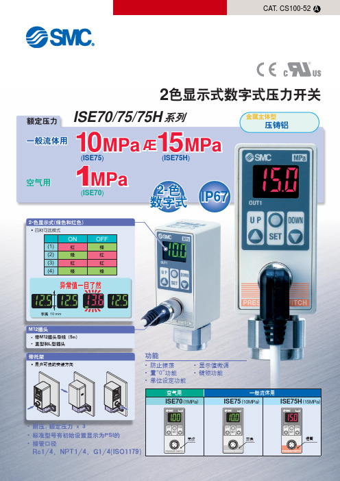
2色显示式数字式压力开关ISE70/75/75H ISE70(1MPa )ISE75(10MPa )一般流体用空气用ISE75H (15MPa )U PSETDOWN MPaU PSETDOWN MPaU PSETDOWNMPa无纹灰色桔黄• 防止振荡• 置“0”功能• 单位设定功能• 显示值微调• 键锁功能功能• 用户可选的安装方向带托架2-色显示式(绿色和红色)• 四种可选模式ONOFF异常值一目了然字高 10 mm• 带M12插头导线 (5m) • 直型和L型插头®10Æ(ISE75)(ISE70)(ISE75H )2-色数字式IP67红绿红绿绿红红绿(1)(2)(3)(4)M12插头一般流体用• 耐压: 额定压力 x 3• 标准型号有初始设置显示为PSI的• 接管口径Rc1/4, NPT1/4, G1/4(ISO1179)系列额定压力空气用压铸铝金属主体型MPa 15MPa1MPa型号表示方法可选项需要可选项部件的场合,按下列型号表示。
注1)˚固定单位: MPa1234茶白蓝黑DC (+)OUT1 (PNP)DC (—)OUT1 (NPN)输出-431234DC (+)NC DC (—)OUT1 (PNP)输出t -65茶白蓝黑2色显示数字式压力开关/空气用ISE70系列12ISE70!"#$规格注1) 在同一设定点有NPN 和 PNP2种功能输出。
注2) G1/4: 符合 ISO1179-1内部回路及配线例固定设置:NPN 集电极开路输出 + PNP 集电极开路输出(2种输出的压力设定点转换输出信号是共同的)最大 30 V (仅NPN), 80 mA, 残留电压 1 V 以下输出-43DC12~24 VDC12~24 V型号表示方法可选项32色显示式数字式压力开关/一般流体用ISE75/75H ¤系列4DC12 ~24 VDC12 ~24 V内部回路及配线图固定设置:NPN 集电极开路输出 + PNP 集电极开路输出(2种输出的压力设定点转换输出信号是共同的)最大 30 V (仅NPN), 80 mA, 残留电压 1 V 以下输出-43输出 -65注1) 在同一设定点有NPN 和 PNP2种功能输出。
SMC PSE530 PSE531 PSE532 PSE533 压力传感器说明书

Instruction ManualCompact Pressure SensorPSE530 / PSE531 / PSE532 / PSE533The intended use of the pressure sensor is to measure the pressure of fluids and provide an analogue output signal.These safety instructions are intended to prevent hazardous situations and/or equipment damage. These instructions indicate the level of potential hazard with the labels of “Caution,” “Warning” or “Danger.”They are all important notes for safety and must be followed in addition to International Standards (ISO/IEC) *1), and other safety regulations. *1)ISO 4414: Pneumatic fluid power - General rules relating to systems. ISO 4413: Hydraulic fluid power - General rules relating to systems. IEC 60204-1: Safety of machinery - Electrical equipment ofmachines. (Part 1: General requirements)ISO 10218-1: Manipulating industrial robots –Safety, etc.• Refer to the product catalogue, operation manual and handling precautions for SMC products for additional information. • Keep this manual in a safe place for future reference.• To ensure safety of personnel and equipment the safety instructions in this manual must be observed, along with other relevant safety practices.CautionCaution indicates a hazard with a low level of risk which, if not avoided, could result in minor or moderate injury.Warning Warning indicates a hazard with a medium levelof risk which, if not avoided, could result in death or serious injury.DangerDanger indicates a hazard with a high level of risk which, if not avoided, will result in death or serious injury.Warning• Ensure compliance with relevant safety laws and standards.All work must be carried out in a safe manner by a qualified person in compliance with applicable national regulations.2 Specifications2.1General Specifications2.2 Piping SpecificationModel No. M5 R06 R07 / N01 Port sizeM5 x 0.8 malethreadø6 reducer1/4 inch reducerMaterial of parts in contact with fluid Pressure sensor: Silicon, O-ring: NBR Body: SUS304Body: PBT W e i g h tWith cable (3 m) 41 g 38 g Without cable7 g3.8 g2.3 Cable Specification Wire Cross section 0.15 mm 2 Wire outside diameter 0.8 mmWire Colours Brown, Blue, BlackSheath material Halogen free heavy duty cableOutside diameter 2.7 mm Cable Length3 mWarning• Special products (-X) might have specifications which are different from those shown in this section. Contact SMC for specific drawings.2.4 Analogue OutputRange Rated Pressurerange A BCFor vacuum 0 to -101 kPa-101 kPa 10.1 kPa For compound -101 to 101 kPa -101 kPa 101 kPa-For low pressure 0 to 101 kPa 0 101 kPa -10.1 kPa For positive pressure-0 to 1 MPa1 MPa-0.1 MPa3 InstallationWarningDo not install the product unless the safety instructions have been read and understood. 3.1 PipingCaution• Before piping make sure to clean up chips, cutting oil, dust etc.• When installing piping or fittings, ensure sealant material does not enter inside the port. When using seal tape, leave 1.5 to 2 threadsexposed on the end of the pipe/fitting.• Tighten fittings to the specified tightening torque.Thread sizeTightening TorqueM51/6 rotation after tightening by hand• Install the piping correctly in a safe place away from water and dust. • When piping, apply a spanner to the piping section of the sensor.• For one touch fittings, insert the tube into the sensor fitting carefully and securely all the way to the bottom.3.2 EnvironmentWarning• Do not use in an environment where corrosive gases, chemicals, salt water or steam are present.• Do not use in an explosive atmosphere.• Do not expose to direct sunlight. Use a suitable protective cover.• Do not install in a location subject to vibration or impact in excess of the product’s specifications.• Do not mount in a location exposed to radiant heat that would result in temperatures in excess of the product’s specifications.4 Wiring4.1 Internal circuit and wiring • Output specificationVoltage output: 1 to 5 VOutput impedance: Approx. 1 kΩ4.2 Connecting the sensor cable (option)• Hold the connector on the sensor cable. Insert it into the sensor paying attention to connector orientation.• The sensor cable connector has a locking cover in order to prevent removal of the connector.• Paying attention to the connector cover direction, install in the sensor, rotate clockwise, and lock it.• To remove the sensor cable, rotate the connector cover anti-clockwise, release the lock, and remove the connector cover.• After removing the connector cover, hold the connector and pull out.4.3 Attaching a sensor connector to the lead wire• The sensor wire sheath should be stripped as shown in the figure. • Do not cut the insulation.• The corresponding wire colour shown in the table should be pushed fully into the correct pin number marked on the sensor connector.Pin No. Wire colour 1 Brown (DC+)2 N.C. ∗3 Blue (DC-) 4Black (IN: 1 to 5 V)• Check that the above preparation has been performed correctly, then press part A by hand to make a temporary connection. • Press part A fully home using a suitable tool.Analogue Output [V]Pressure 1 to 5 VDCORIGINAL INSTRUCTIONSModelPSE530 PSE531 PSE532 PSE533 Rated Pressure range 0 to 1 MPa 0 to -101kPa0 to 101 kPa-100 to 100 kPaExtended Analogue output range -0.1 to 0 MPa 10.1 to 0 kPa -10.1 to 0 kPa-Withstand pressure 1.5 MPa500 kPaApplicable fluid Air, inert gases and incombustible gases Power supply voltage 12 to 24 VDC ±10%(with 10% max. voltage ripple)Current consumption15 mA or lessAnalogue output specification1 to 5 VDC (rated pressure range) 0.6 to 1 VDC (extended analogue output range)Output impedance: Approx. 1 kΩ Accuracy (at 25°C) ±2% F.S. (rated pressure range)±5% F.S. (extended analogue output range)Linearity ±1% F.S. Repeatability ±1% F.S.Power supply voltage effect±1% F.S. or less (based on the analogue output at 18 V ranging from 12 to 24 VDC)Temperature characteristics±2% F.S. (at 25°C)E n v i r o n m e n t a lEnclosureIP40Ambient temperature Operation: 0 to 50°C Storage: -10 to 70°C (no condensation or freezing) Ambient humidity Operation, Storage: 35 to 85% RH(no condensation) Withstand voltage 1000 VAC or more (50/60 Hz), 1 minute(between lead block and case)Insulation resistance50 MΩ or more at 500 VDC (between lead block and case)• The sensor connectors cannot be re-used once they have been pressed fully closed. If connection failure or incorrect wiring occurs a new sensor connector must be used.• When connecting the sensor to a PSE200 / PSE300 series monitor, use the connector for sensor lead wire (ZS-28-C) or an e-Con* connector from the table below.Maker Model No.Sumitomo 3M 37104-3101-000FL Tyco Electronics3-1473562-4 OMRONXN2A-1430* Refer to the manufacturers e-Con connector catalogue.Refer to the catalogue or operation manual on the SMC website (URL:https:// ) for How to order information.Refer to the catalogue or operation manual on the SMC website (URL: https:// ) for outline dimensions.7.1 General MaintenanceCaution• Not following proper maintenance procedures could cause the product to malfunction and lead to equipment damage.• If handled improperly, compressed air can be dangerous. Maintenance of pneumatic systems should be performed only by qualified personnel.• Before performing maintenance, turn off the power supply and be sure to cut off the supply pressure. Confirm that the air is released to atmosphere.• After installation and maintenance, apply operating pressure and power to the equipment and perform appropriate functional and leakage tests to make sure the equipment is installed correctly.• If any electrical connections are disturbed during maintenance, ensure they are reconnected correctly and safety checks are carried out as required to ensure continued compliance with applicable national regulations.• Do not make any modification to the product.• Do not disassemble the product, unless required by installation or maintenance instructions.8.1 Limited warranty and Disclaimer/Compliance Requirements Refer to Handling Precautions for SMC Products.This product should not be disposed of as municipal waste. Check your local regulations and guidelines to dispose of this product correctly, in order to reduce the impact on human health and the environment.Refer to or www.smc.eu for your local distributor / importer.URL : https:// (Global) https://www.smc.eu (Europe) SMC Corporation, 4-14-1, Sotokanda, Chiyoda-ku, Tokyo 101-0021, JapanSpecifications are subject to change without prior notice from the manufacturer. © 2021 SMC Corporation All Rights Reserved. Template DKP50047-F-085M。
SMC数字式压力开关-ZSE40A(F)ISE40A 系列

范围 真空压用 混合压用 正压用
额定压力范围 0.0~-101.3kPa -100.0~100.0kPa -0.100~1.000MPa
A 10.1kPa
- -0.100MPa
B 0 -100.0kPa 0
C -101.3kPa 100.0kPa 1.000MPa
C
压力
各部的名称
输出(OUT1)显示(橙色)
开关输出OUT1在ON时灯亮。
输出(OUT2)显示(橙色)
开关输出OUT2在ON时灯亮。
△键
模式的选择及增加ON/OFF设定值。 切换至峰值显示模式时使用。
△
LCD显示
显示现在的压力状态、设定模式的状态、所选择的显 示单位、错误代码。 可选择通常红或绿的单色显示,输出连动时,由绿色 变成红色或由红色变成绿色等4种显示方法。
托架A
托架B
托架D
直接(壁安装)
ZSE/ISE40系列 New ZSE/ISE40A系列
面板安装
与ZSE40/ISE40系列有安装互换性。
系列
系列
ZSE40A (真空压)
ZSE40AF (混合压)
ISE40A (正压)
0.0~-101.3kPa
额定压力范围 0
-101kPa
-100.0~100.0kPa
最小负载阻抗 50Ω
2.4~20mA±2.5%F.S.
自动移位输入 显示方式 显示精度 动作指示灯
保护等级 使用温度范围 使用湿度范围 耐环境 耐电压 绝缘电阻 耐振动 耐冲击 温度特性
无电压输入(有触点或无触点)、Low水平 0.4V以下、输入时间 5ms以上 3 1/2位7段LCD2色显示(红色/绿色)
W1/WF1/M5/C4/C6 的场合
SMCISE20—N说明书
SMCISE20—N说明书1.基本原理ISE20—N采用压电效应来实现压力的测量。
当介质的压力作用于传感器的感应元件时,感应元件内部的晶体振荡频率发生变化。
通过测量频率变化的大小,可以准确地获得介质的压力信息。
2.操作方法ISE20—N的操作非常简单。
首先,通过终端上的键盘设置传感器的相关参数,如单位、输出范围等。
然后,将传感器与测量系统连接,并按照相应的接线方式连接。
接着,打开电源,待传感器完成初始化后,即可进行正常的压力测量操作。
3.技术参数ISE20—N具有以下优秀的技术参数:-测量范围:0-1000kPa-准确度:±0.5%FS- 响应时间:≤1ms- 输出信号:4-20 mA / 0-10 V / Digital-工作温度范围:-10℃-60℃-防护等级:IP67-过载能力:200%FS4.维护保养为确保ISE20—N的正常工作和延长使用寿命,需要进行定期的维护保养。
具体的维护保养事项包括:-定期清洁传感器的外壳,避免灰尘和污垢对传感器的影响;-检查传感器的接线是否松动,确保传感器与测量系统的正常连接;-定期校准传感器的测量精度,以确保其准确性和稳定性。
5.应用领域ISE20—N广泛应用于工业自动化和控制系统中的压力测量。
它适用于各种介质的压力监测和控制,如液体、气体、蒸汽等。
其高精度、高性能的特点,使得它在化工、食品加工、机械制造等行业中得到了广泛的应用。
总结:SMCISE20—N是一种高精度、高性能的数字压力传感器,具有广泛的应用领域和优越的性能特点。
本说明书详细介绍了ISE20—N的基本原理、操作方法、技术参数以及维护保养等方面的内容。
希望本说明书能够帮助用户更好地了解和使用ISE20—N,从而满足其在压力测量和控制领域的需求。
smc数显压力表设定方法_日本SMC数显压力表中文说明书ISE40A-01-P-ML

smc数显压⼒表设定⽅法_⽇本SMC数显压⼒表中⽂说明书ISE40A-01-P-ML⽇本SMC数显压⼒表中⽂说明书ISE40A-01-P-ML特点:●IP65●适合流体: 空⽓, ⾮腐蚀性⽓体, ⾮燃性⽓体●多可同时拷贝⾄10台●3步设定●带快换接头配管规格 01 R1/8(带M5内螺纹)输出规格 P PNP开路集电极1输出单位规格 M SI单位固定可选项1 - ⽆可选项2 - 使⽤说明书:-;校正证明书:空⽓,⾮腐蚀性⽓体,不可燃⽓体12⾄24 VDC o 10%,纹波(pp)10%或更低(带电源极性保护)45 mA或更低NPN或PNP开路集电极1输出或2输出80毫安28 V(NPN输出)1 V或更低2.5 ms(具有防抖功能:20,100,500,1000,2000 ms)是的o 0.2%F.S。
o 1位数变量(0或以上)注1设定压⼒范围是设定时可能的压⼒范围。
满⾜开关规格(精度,线性度等)的压⼒范围的额定压⼒范围。
虽然可以设定超出额定压⼒范围的值,但即使值保持在规定范围内,也不能保证规格设定的压⼒范围。
当压⼒开关⽤于⽔和灰尘飞溅的地⽅时可能会发⽣,将管插⼊⼤⽓通风⼝,并将另⼀根管路径管的末端到⼀个安全的地⽅,远离⽔和灰尘。
SMC TU 0425(聚氨酯,O.D。
?4,I.D.?2.5)适合压⼒开关。
KPQL06-M5KSL04-M5KSH06-01SSY5420-5DZ-01 24DCVF5210-5DZ-03CKZT50-105T-DCK9412K CKZT50-105T-DCK9413K KQ2R06-10AMY1B80ZH10BKQ2E12-04PF2W720-F04-27(NPN) TS0806BU-20 20⽶/卷KQ2H16-00AKQGH08-03SMDBB63-200AW40-03H-X2050AW30-03E-RVT317E-5DZ-02AW30-F03ISE40A-01-P-MLEVS7-6-FG-D-3CVO-QC96 SDB 63-100-M9 PW KQ2L16-04ASKQ2H16-04ASKQ2U16-00AG27-20-01BBS6-4KK130P-01MSKK130S-01MSISE40A-C6-T-X501CK1B50-50YZCK1B63-50YZCK1B63-75YZCK1B63-100YZCK1B63-125YZCKZP40-40-DCK048JKMGPL40-50-X986MGPA50-50-X986VBA10A-02VVQC2000-3A-1-C10-SVVQC2000-1A-D-C8VVQC2000-2A-1-C10-SKQGH10-02SKQGS10-02SKQGH08-01SKQGS08-01SMGPL80-75-X986MGZL32Z-75-M9PWVAN700-12(11/4')MBD50-100MBD63-150CM2B32-25ACDQ2B63-50DZ-P3DWSECDQ2B63-50DCMZ-P3DWSCMBT80TF-75ZCQ2A63-25DCMZ-XC35CQ2A50-50DCMZ-XC35C96SB63-25-XC35C96SB63-50-XC35C96SB63-160-XC35CDQ2B40-30DCMMGPL40-25Z-M9BWSDPC-XC35CDQ2B40-35DCMZ-M9BWSDPC-XC35⽇本SMC数显压⼒表中⽂说明书ISE40A-01-P-ML。
SMC数字式压力开关ZSE30A(F),ISE30A使用说明书

No.PS※※-OML0002CN-G 使用说明书产 品 名 称数字式压力开关形式/系列/型号ZSE30A(F)ISE30A目录安全注意事项 2型式表示·型号体系 8产品各部的名称及功能 10用语说明 11安装・设置 14设置方法 14配管方法 17配线方法 18压力的设定 21什么是测试模式 21功能设定 24什么是功能选择模式 24出厂设定 24 F0 单位切换功能 26 F1 OUT1的设定 27 F2 OUT2的设定 30 F3 响应时间的设定 30 F4显示分辨率的设定 31 F5 自动预设功能的设定 32 F6 显示值微调的设定 34 F7 省电模式的设定 35 F8 密码输入的设定 36特殊功能的设定 37 F90 全功能的设定 37 F97 复制功能的选择 39 F98 输出确认 41 F99 恢复出厂设置 43其他设定 44维护 47忘记密码的情况 48故障一览表 49规格 56规格表 56外形尺寸图 58安全注意事项此处所示的注意事项是为了确保您能安全正确地使用本产品,预先防止对您和他人造成危害和损失而制定的。
这些注意事项,按照危害和损伤的大小及紧急程度分为「注意」「警告」「危险」三个等级。
无论哪个都是与安全相关的重要内容,所以除了遵守国际规格(ISO/IEC)、日本工业规格(JIS)※1)以及其他安全法规※2)外,这些内容也请务必遵守。※1) ISO 4414: Pneumatic fluid power -- General rules relating to systemsISO 4413: Hydraulic fluid power -- General rules relating to systemsIEC 60204-1: Safety of machinery -- Electrical equipment of machines (Part 1: General requirements) ISO 10218-1992: Manipulating industrial robots-SafetyJIS B 8370: 空气压系统通则JIS B 8361: 油压系统通则JIS B 9960-1: 机械类的安全性、机械的电气装置(第1部: 一般要求事项)JIS B 8433-1993: 产业用操作机器人-安全性等※2) 劳动安全卫生法等注意:误操作时,有人员受伤的风险,以及物品破损的风险。警告:误操作时,有人员受到重大伤害甚至死亡的风险。
SMC压力传感器调整说明书 ZSE AISE A

5、错误显示与对策
错误
错误显示 报错原因
名称
处理对策
过电流
开关输出的负载电流超过 80mA
切断电源,检查输出部分电路, 确保电流在 80mA 以内后重新 开启电源
残压 异常
压力 异常
复制功 能异常
执行“清零”操作时供给压力 供给压力在指定范围内时再
不在±7%F.S(. 混合压型±3.5%) 执行“清零”操作 范围内.
功能设定模式下选择 F3,按
按
进入响应时间设定。
键
进入响应时间设定
响应时间设定: 按 和 选择响应时间值,按 确认
交替显示
响应时间
设定值
按 键确认
返回功能选择模式
F3-响应时间设定完成
5)、F4-显示精度设定:调整显示精度,用于消除末尾显示值跳动。
功能设定模式下选择 F4,按 进入显示精度设定。
按键
如果无 OUT2, 将输出检查部分 恢复为 A-常规输 出后, 按 键设定。
返回功能选择 模式
F98-输出检查完成
强制 ON
如果有 OUT2, 按 键设定, 设定方法同上。 设定完成后按住
键 2 秒钟以上, 返回测量模式。
测量模式
10
4)、F99-恢复出厂设置:用此功能将所有设置恢复为出厂设置。
在功能设定模式下选择 F99,按 进入恢复出厂设置。
主压力开关为要复制的压力、功能设置数据的来源,是被复制对象;
从压力开关为压力、功能设置数据要复制到的目的地。
从压力开关
主压力开关
1
2
N(N 最大为 10)
8
操作方法:在主压力开关的功能设定模式下选择 F97,按 进入复制功能设定。
(SMC压力传感器调整说明书)ZSE30AISE30A

Z/ISE30A 系列压力开关设定说明设定顺序:通电—测量模式—零点校正—功能设定—测量模式产品通电后,自动进入压力测量模式,第一次使用时,请按如下顺序操作。
1、零点校正:产品第一次使用时,通电且不施加气压时,如果显示值不为零,和键同时按住1s 以上,显示值归零。
2、基本功能设定:测量模式下按住键2s 以上,压力开关进入功能设定模式,显示屏显示为。
按和键选择对应功能后按进入详细功能设置。
备注:部分功能为可选功能,根据型号而定。
特定型号下如果不包含某可选功能,对应位置显示。
全部功能列表:项目出厂设置F0:单位选择功能 ISE-Mpa,ZSE-KPa,Option P-psi F1:OUT1规格设定 迟滞模式,常开F2:OUT2规格设定 迟滞模式,常开 F3:响应时间设定 2.5 ms F4:显示精度设定 1/1000 F5:自动预设功能设定 手动模式F6:显示值校正 0% F7:省电模式选择 OFF F8:密码锁设定OFF1)F0-单位选择功能可选功能,部分型号无此功能。
单位不同,显示屏开显示的数值范围不同。
操作方法:按和键选择对应单位,按键确认。
测量模式按住键2s 以上功 能 选 择 模 式功能设定2)F1-OUT1输出规格设定方法:此部分可设置输出类别(迟滞型/比较型)和输出模式(常开/常闭)设定。
按键进入单位选择模式按和键选择对应单位交替显示按键完成设定返回到功能选择模式,屏幕显示F0F0-单位选择功能设定完成输出模式常开型 出厂时默认设置常闭型迟滞模式(出厂时默认设置) 压力输出迟滞(H-1)压力输出压力输出迟滞(H-1)压力输出比较模式(也称窗口比较模式) 迟滞模式(出厂时默认设置) 比较模式(也称窗口比较模式) 迟滞(H1) 迟滞(H1)迟滞(H1) 迟滞(H1)功能选择模式下按和至屏幕显示,然后按进入OUT1规格设定。
压力设定状态:此状态下设定压力开关输出的ON/OFF 点。
以迟滞型为例:输出方法:当压力超过设定值时,开关输出变为ON 。
ZSE40F(SMC数显压力开关)手册

文件No.PS※※-OMM0006-A 使用说明书产 品 名 称数字式压力开关型式/系列/型号ZSE40A(F)ISE40A目录安全注意事项 2 型式表示・型号体系 9 产品各部品名称及功能 11 用语的定义及用语集 12 安装・设置 15 设置方法 15 配管方法 17 配线方法 19 压力设定 21 什么是设定模式 21 功能设定 23 什么是功能选择模式 23 出厂设定 23 F0 单位切换功能 25 F1 OUT1的设定 26 F2 OUT2的设定 29 F3 响应时间的设定 31 F4 自动预设功能的设定 32 F5 模拟输出/自动移位输入的设定 34 F6 显示值微调整的设定 36 F11 分辨率的设定 37 F80 省电模式的设定 38 F81密码输入的设定 39 特殊功能的设定 40 F90 全功能的设定 40 F97 复制功能的选择 42 F98 输出确认 44 F99 恢复出厂设置 46 其他设定 47 维护 50 忘记密码的情况 51 故障的消除 52 规格 59 规格表 59 外形尺寸图 61安全注意事项这里所示的注意事项是为了能安全正确的使用本产品,预先防止对您和他人造成危害或损失。
为了表示这些事项的危险程度,将注意事项分成「注意」「警告」和「危险」三个等级。
请您也遵守和安全相关的其他重要内容,如国际规格(ISO/IEC)、日本工业规格(JIS)※1以及其他安全法规※2。
*1) ISO 4414: Pneumatic fluid power -- General rules relating to systemsISO 4413: Hydraulic fluid power -- General rules relating to systemsIEC 60204-1: Safety of machinery -- Electrical equipment of machines (Part 1: General requirements) ISO 10218-1: Robots for industrial environments—Safety requirements –Part 1: RobotJIS B 8370: 空气压系统通则JIS B 8361: 油压系统通则JIS B 9960-1: 机械类的安全性-机械的电气装置(第1部:一般要求事项)JIS B 8433-1: 工业机器人- 安全要求事项-第1部: 机器人等*2) 劳动安全卫生法 等注意: 错误操作时,人和设备可能受到损伤的事项。
SMC压力传感器调整说明书

SMC压力传感器调整说明书SMC压力传感器是一种广泛应用于工业生产中的重要设备。
作为一种关键的检测器,它能够帮助操作者监测工业生产中的压力值,并进行调整,从而确保产品的质量和生产的稳定性。
在实际的应用过程中,对SMC压力传感器的正确调整是至关重要的。
本文将为大家提供一份详细的SMC压力传感器调整说明书。
仪器器材准备在进行SMC压力传感器的调整之前,我们首先需要准备好一些仪器和器材。
这些器材的使用是为了保证我们能够进行准确、稳定和可靠的测量。
主要的器材如下:1. SMC压力传感器2. 0-5V电压信号发生器3. 电子式万用表4. 气源压力表5. 压力校验器6. 电脑或手机APP调整步骤1. 调整输出信号电压首先,我们需要通过电压信号发生器来给SMC压力传感器提供一个规定的电压输入信号。
在此之前,我们需要先将电压信号发生器的信号输出与SMC压力传感器的输入端口相连接。
调整过程中,我们需要慢慢提高输入信号,直到SMC压力传感器输出的电压信号为满电压的80%为止。
在此之后,我们需要将电压信号逐步降低,直到输出信号电压达到满量程的10-90%。
2. 调整零点偏移在电压信号的调整完成之后,下一步我们需要对SMC压力传感器的零点偏移进行校准。
在此之前,我们需要将电压信号发生器的输出电压设置为0,这样可以避免误差。
调整过程中,我们需要根据电子式万用表测量出SMC压力传感器当前的输出电压,并与实际的零点输出电压进行比较。
如果出现偏差,我们需要调整压力传感器的零点来进行校准。
3. 调整满量程在进行零点偏移校准之后,我们需要对SMC压力传感器的满量程进行校准。
在此之前,我们需要按照之前的方法调整电压信号到满量程。
调整过程中,我们需要根据电子式万用表测量出SMC压力传感器当前的输出电压,并与实际的满量程输出电压进行比较。
如果出现偏差,我们需要调整压力传感器的满量程来进行校准。
4. 调整灵敏度和输出信号最后一步,我们需要根据实际情况来调整SMC压力传感器的灵敏度和输出信号。
SMC压力传感器调整说明书ZSE30AISE30A

SMC压力传感器调整说明书ZSE30AISE30A关键信息项:1、传感器型号:ZSE30A/ISE30A2、调整目的3、调整工具4、调整步骤5、安全注意事项6、故障排除方法1、引言本协议旨在为用户提供关于 SMC 压力传感器 ZSE30A/ISE30A 的详细调整说明,以确保其正常运行和准确测量压力。
11 适用范围本协议适用于 SMC 压力传感器 ZSE30A/ISE30A 的调整操作。
2、调整目的21 确保传感器测量精度通过调整,使传感器能够准确测量压力值,减少误差。
22 适应不同的工作环境和压力范围根据实际工作需求,调整传感器的参数,以适应各种工作条件。
23 优化传感器性能提高传感器的响应速度、稳定性和可靠性。
3、调整工具31 专用调试设备如 SMC 提供的特定调试工具或软件。
32 标准压力校验仪用于提供准确的压力标准值,以校准传感器。
33 螺丝刀等常用工具用于拆卸和安装传感器的外壳及相关部件。
4、调整步骤41 准备工作411 关闭相关设备的电源,确保操作安全。
412 将传感器从系统中拆卸下来,放置在干净、平稳的工作台上。
42 外观检查421 检查传感器外壳是否有损坏、变形等情况。
422 检查传感器的连接接口是否清洁、无异物。
43 连接调试设备431 将专用调试设备或软件与传感器正确连接。
432 按照调试设备的说明书进行设置和初始化。
44 压力校准441 使用标准压力校验仪向传感器施加不同的压力值。
442 观察传感器的输出值,并与标准压力值进行对比。
443 通过调试设备调整传感器的参数,使输出值与标准压力值相符。
45 功能测试451 对调整后的传感器进行功能测试,包括压力上升和下降时的响应情况。
452 检查传感器在不同压力范围内的稳定性和重复性。
46 安装与恢复461 将调整好的传感器安装回原系统。
462 开启相关设备的电源,检查传感器的工作状态是否正常。
5、安全注意事项51 在操作过程中,务必遵循相关的安全操作规程,防止发生意外事故。
smc数显压力表设定方法
smc数显压力表设定方法SMC数显压力表设定方法。
SMC数显压力表是一种常用的压力测量仪器,广泛应用于工业领域。
正确的设定方法可以确保其准确度和稳定性,提高工作效率。
下面将介绍SMC数显压力表的设定方法,希望能对您有所帮助。
首先,确保SMC数显压力表的电源已接通,并且压力表已经连接到相应的管路上。
接下来,按照以下步骤进行设定:1. 检查零点。
在设定压力表之前,需要先检查压力表的零点。
将压力表放置在零压力状态下,观察数显屏幕上的数值是否稳定在零。
如果不稳定,需要进行调零操作,确保数显压力表的零点准确。
2. 设定量程。
根据实际测量需求,设定SMC数显压力表的量程。
量程设定是根据被测介质的最大压力来确定的,确保压力表的量程能够满足实际测量需求。
3. 调整显示单位。
SMC数显压力表通常可以显示不同的压力单位,如MPa、bar、psi等。
根据实际需要,选择合适的显示单位,并进行相应的设定。
4. 校准。
在设定完成后,需要进行校准操作。
将压力表连接到标准压力源上,调节压力源输出的压力值,观察数显压力表的显示数值是否与标准值一致。
如果不一致,需要进行校准调整,直到数显压力表的显示数值与标准值一致为止。
5. 确认设定。
在完成上述步骤后,需要再次确认数显压力表的设定是否准确。
可以通过连接到实际工作环境中进行实时测量,验证数显压力表的准确性和稳定性。
总结。
SMC数显压力表的设定方法并不复杂,但需要注意细节和准确性。
正确的设定可以保证压力表的准确度和稳定性,提高工作效率,确保生产安全。
希望以上介绍能够帮助您正确使用SMC数显压力表,并取得满意的测量结果。
SMC压力传感器的详细资料@日本SMC传感器、压力开关
SMC压力传感器的详细资料 @日本SMC传感器、压力开关压力传感器是工业实践中最为常用的一种传感器。
一般普通压力传感器的输出为模拟信号,模拟信号是指信息参数在给定范围内表现为连续的信号。
或在一段连续的时间间隔内,其代表信息的特征量可以在任意瞬间呈现为任意数值的信号。
而通常使用的压力传感器主要是利用压电效应制造而成的,这样的传感器也称为压电传感器。
压力传感器是使用最为广泛的一种传感器。
传统的压力传感器以机械结构型的器件为主,以弹性元件的形变指示压力,但这种结构尺寸大、质量重,不能提供电学输出。
随着半导体技术的发展,半导体压力传感器也应运而生。
其特点是体积小、质量轻、准确度高、温度特性好。
特别是随着MEMS技术的发展,半导体传感器向着微型化发展,而且其功耗小、可靠性高。
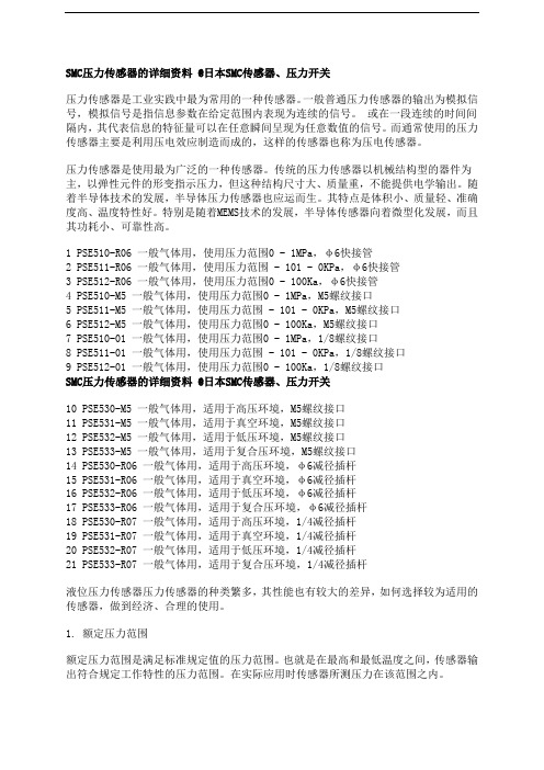
1 PSE510-R06 一般气体用,使用压力范围0 - 1MPa,φ6快接管2 PSE511-R06 一般气体用,使用压力范围 - 101 - 0KPa,φ6快接管3 PSE512-R06 一般气体用,使用压力范围0 - 100Ka,φ6快接管4 PSE510-M5 一般气体用,使用压力范围0 - 1MPa,M5螺纹接口5 PSE511-M5 一般气体用,使用压力范围 - 101 - 0KPa,M5螺纹接口6 PSE512-M5 一般气体用,使用压力范围0 - 100Ka,M5螺纹接口7 PSE510-01 一般气体用,使用压力范围0 - 1MPa,1/8螺纹接口8 PSE511-01 一般气体用,使用压力范围 - 101 - 0KPa,1/8螺纹接口9 PSE512-01 一般气体用,使用压力范围0 - 100Ka,1/8螺纹接口SMC压力传感器的详细资料 @日本SMC传感器、压力开关10 PSE530-M5 一般气体用,适用于高压环境,M5螺纹接口11 PSE531-M5 一般气体用,适用于真空环境,M5螺纹接口12 PSE532-M5 一般气体用,适用于低压环境,M5螺纹接口13 PSE533-M5 一般气体用,适用于复合压环境,M5螺纹接口14 PSE530-R06 一般气体用,适用于高压环境,φ6减径插杆15 PSE531-R06 一般气体用,适用于真空环境,φ6减径插杆16 PSE532-R06 一般气体用,适用于低压环境,φ6减径插杆17 PSE533-R06 一般气体用,适用于复合压环境,φ6减径插杆18 PSE530-R07 一般气体用,适用于高压环境,1/4减径插杆19 PSE531-R07 一般气体用,适用于真空环境,1/4减径插杆20 PSE532-R07 一般气体用,适用于低压环境,1/4减径插杆21 PSE533-R07 一般气体用,适用于复合压环境,1/4减径插杆液位压力传感器压力传感器的种类繁多,其性能也有较大的差异,如何选择较为适用的传感器,做到经济、合理的使用。
SMC压力传感器调整说明书 ZSE AISE A

Z/ISE30A 系列压力开关设定说明设定顺序:通电—测量模式—零点校正—功能设定—测量模式产品通电后,自动进入压力测量模式,第一次使用时,请按如下顺序操作。
1、零点校正:产品第一次使用时,通电且不施加气压时,如果显示值不为零,和键同时按住1s 以上,显示值归零。
2、基本功能设定:测量模式下按住键2s 以上,压力开关进入功能设定模式,显示屏显示为。
按和键选择对应功能后按进入详细功能设置。
备注:部分功能为可选功能,根据型号而定。
特定型号下如果不包含某可选功能,对应位置显示。
全部功能列表:项目出厂设置F0:单位选择功能 ISE-Mpa,ZSE-KPa,Option P-psi F1:OUT1规格设定 迟滞模式,常开F2:OUT2规格设定 迟滞模式,常开 F3:响应时间设定 2.5 ms F4:显示精度设定 1/1000 F5:自动预设功能设定 手动模式F6:显示值校正 0% F7:省电模式选择 OFF F8:密码锁设定OFF1)F0-单位选择功能可选功能,部分型号无此功能。
单位不同,显示屏开显示的数值范围不同。
操作方法:按和键选择对应单位,按键确认。
测量模式按住键2s 以上功 能 选 择 模 式功能设定2)F1-OUT1输出规格设定方法:此部分可设置输出类别(迟滞型/比较型)和输出模式(常开/常闭)设定。
按键进入单位选择模式按和键选择对应单位交替显示按键完成设定返回到功能选择模式,屏幕显示F0F0-单位选择功能设定完成输出模式常开型 出厂时默认设置常闭型迟滞模式(出厂时默认设置) 压力输出迟滞(H-1)压力输出压力输出迟滞(H-1)压力输出比较模式(也称窗口比较模式) 迟滞模式(出厂时默认设置) 比较模式(也称窗口比较模式) 迟滞(H1) 迟滞(H1)迟滞(H1) 迟滞(H1)功能选择模式下按和至屏幕显示,然后按进入OUT1规格设定。
压力设定状态:此状态下设定压力开关输出的ON/OFF 点。
以迟滞型为例:输出方法:当压力超过设定值时,开关输出变为ON 。
SMC_PSE200显示器中文设定说明
· 确认数值,按 SET 键。 · 全部设定结束,返回测量模式。
自动预设 初期设定选择自动预设时,可以从测定压力计算出恰当的设定值,自动保存。
1.自动预设 OUT1
· 测量模式下,按 ▲键,选择需要设定的通道,然后按 SET 键,
显示“AP1”。
2.OUT1 的装置准备
· 确定数值,按 SET 键。
3.输入 OUT2“P_3、P_4”的设定值(只对应通道 CH1)
· 同 1、2 相同,按▲ 或 ▼ 键,改变设定值大小。
单按一次▲ 或 ▼ 键,数值改变 1digit,连续按则数值连续变化。
· 确定数值,按 SET 键。
4.确认自动移位功能
· “C_5”(CH2~4 设定时为“C_3”)与自动移位值交替闪烁显示。
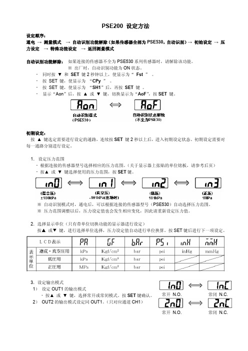
自动识别功能解除: 如果连接的传感器不全为 PSE530 系列传感器时,请解除该功能。 ※ 出厂时,自动识别功能为 ON 状态。
· 同时按 ▼ 和 SET 键 2 秒钟以上,使显示为“ Fst ” 。 · 按 SET 键,使显示为 “CPy ” 。 · 按 SET 键,使显示为 “SH1”后,再按 SET 键 。 · 显示“Aon”后,按 ▲ 或 ▼ 键,切换显示为“AoF”,按 SET 键。
2.选择显示单位(只有带单位切换功能的显示器进行设定) 按▲ 或▼ 键,进行选择单位选择,压力设定值自动进行单位换算。按 SET 键后进行下一项设定。
3.设定输出模式 1) 设定 OUT1 的输出模式
· 按▲ 或 ▼ 键,选择常开或常闭模式。按 SET 键确认。
2) OUT2 的输出模式设定同 OUT1。(只对应通道 CH1)
· 确定数值,按 SET 键。
- 1、下载文档前请自行甄别文档内容的完整性,平台不提供额外的编辑、内容补充、找答案等附加服务。
- 2、"仅部分预览"的文档,不可在线预览部分如存在完整性等问题,可反馈申请退款(可完整预览的文档不适用该条件!)。
- 3、如文档侵犯您的权益,请联系客服反馈,我们会尽快为您处理(人工客服工作时间:9:00-18:30)。
产品名称:SMC数显压力传感器
传感器(英文名称:transducer/sensor)是一种检测装置,能感受到被测量的信息,并能将感受到的信息,按一定规律变换成为电信号或其他所需形式的信息输出,以满足信息的传输、处理、存储、显示、记录和控制等要求。
传感器的特点包括:微型化、数字化、智能化、多功能化、系统化、网络化。
它是实现自动检测和自动控制的首要环节。
传感器的存在和发展,让物体有了触觉、味觉和嗅觉等感官,让物体慢慢变得活了起来。
通常根据其基本感知功能分为热敏元件、光敏元件、气敏元件、力敏元件、磁敏元件、湿敏元件、声敏元件、放射线敏感元件、色敏元件和味敏元件等十大类。