ARM801 通用安装调试指南v2_CHINES2013.3.30
S801用户手册
5
物理参数 .....................................................................................................................................
5
验收及拆装
概述 ..............................................................................................................................................
7
拆装 ..............................................................................................................................................
7
贮藏 ..............................................................................................................................................
S801+ 运行配置 介绍 .............................................................................................................................................. 27 用户界面 ...................................................................................................................................... 27 设置及起动................................................................................................................................... 28 保护参数 ...................................................................................................................................... 30
IIM-801系列智能一体化监控装置使用说明书
装置后视面板如图 4-2 所示:
图 4-2 装置后视面板 屏体安装开孔尺寸如图 4-3 所示:
-4-
许继电源有限公司
IIM-801 系列智能一体化监控装置使用说明书
图 4-3 开孔尺寸
4.2 装置端口定义
端子 A 的定义如下表所示:
接口名 称
端子号
代号
1
A
COM1
2
B
3
A
COM2
4
B
5
GND
6
A
COM3
装置在系统中所处的位置如图 1-1 所示:
图 1-1 装置在系统中所处的位置图
2 产品特点 2.1 产品开发平台化 系统设计遵循“基础平台+应用平台+工程配置”的设计思想,采用跨平台技术,可
以在 Windows/Unix/Linux 等不同的操作系统下运行,本产品采用 Linux 内核,保证了 系统运行的稳定性。
数量上和信息点上有差异,但主体内容不变。
6.1
串口服务器NP801应用说明

串口设备联网服务器用户手册RS-232/485/422 —TCP/IPSerial Device Server User’s ManualVersion 6.11目录1产品简介 (1)1.1产品特色 (1)1.2技术规格 (2)1.3接口特性: (4)连接电源 (4)连接网络 (4)连接串口设备 (5)1.4软件安装 (5)系统要求 (5)软件安装 (6)操作说明 (6)2使用指南 (7)2.1串口服务器参数 (7)2.2配置参数 (8)21产品简介1.1产品特色NP801三合一串口设备联网服务器(G&S NETPORT系列产品之一,以下简称NP801)是我司自主研发生产的工业级串口联网设备。
采用32位ARM处理器,嵌入式实时多任务操作系统,提供10M/100M的通讯,使设备运行更加稳定,可靠。
NETPORT系列串口服务器让您无需投入大量资金来更换或升级原有软件和硬件系统,就可以让您原有的RS-232/422/485串口设备轻松实现以太网互联,为串口数据信息提供高效、安全、稳定的数据通道。
目前该系列产品已广泛应用于:◢工厂自动化控制◢机房监控◢PLC控制◢智能电表◢生物识别装置、读卡器◢安保系统◢机电仪器联网控制等等领域1NP801特点:●采用32位工业级处理器,高可靠性及低功耗●10/100M自适应以太网接口,串口界面多种可选●所有信号内置15 KV ESD保护,RS485 每线600W TVS保护,网络1.5KV电磁隔离●保证最高波特率115.2Kbps下,长时间双向文件传输不丢1个bit●支持Windows实COM串口驱动程序,支持离线设置虚拟串口,上电即插即用。
●支持通用Socket操作模式,包括TCP Server/Clint和UDP。
●支持断电或者断网自动恢复,免去很多维护成本●支持状态监视。
提供了多个指示灯来分析服务器的工作状态●平台软件自动搜索服务器●支持7-24V DC宽电压输入,并提供Terminal和Power Jack两种电源接口方式,充分体贴现场安装环境●提供方便的固件升级,保证不断提升产品性能和可靠性,保障客户的投资。
ARM开发调试教程
ARM开发调试教程作者:李希岗创建日期:2003年5月20日修改日期:2003年5月20日版本:说明:本文是我学习ARM开发以来的一些经验总结,以自己设计的S3C44B0X板为例,给出我调试开发ARM开发板的一些最基础知识。
我只是在自己的开发板调试过并且经验有限,有些知识只能做为参考,不一定准确,就算给大家一个“例程”吧,如果大家有不同意见,希望多多指正!硬件篇(一)开发板的整体架构我设计的开发板是在三星44B0 demo板的基础上,参考网络上相关的资料,加入我的思想开发的。
以下是该开发板的整体架构:(二)开发板的焊接贴片式元器件的拆卸、焊接宜选用200~280℃调温式尖头烙铁。
贴片式电阻器、电容器的基片大多采用陶瓷材料制作,这种材料受碰撞易破裂,因此在拆卸、焊接时应掌握控温、预热、轻触等技巧。
控温是指焊接温度应控制在200~250℃左右。
预热指将待焊接的元件先放在100℃左右的环境里预热1~2分钟,防止元件突然受热膨胀损坏。
轻触是指操作时烙铁头应先对印制板的焊点或导带加热,尽量不要碰到元件。
另外还要控制每次焊接时间在3秒钟左右,焊接完毕后让电路板在常温下自然冷却。
以上方法和技巧同样适用于贴片式晶体二、三极管的焊接。
贴片式集成电路的引脚数量多、间距窄、硬度小,如果焊接温度不当,极易造成引脚焊锡短路、虚焊或印制线路铜箔脱离印制板等故障。
拆卸贴片式集成电路时,可将调温烙铁温度调至260℃左右,用烙铁头配合吸锡器将集成电路引脚焊锡全部吸除后,用尖嘴镊子轻轻插入集成电路底部,一边用烙铁加热,一边用镊子逐个轻轻提起集成电路引脚,使集成电路引脚逐渐与印制板脱离。
用镊子提起集成电路时一定要随烙铁加热的部位同步进行,防止操之过急将线路板损坏。
换入新集成电路前要将原集成电路留下的焊锡全部清除,保证焊盘的平整清洁。
然后将待焊集成电路引脚用细砂纸打磨清洁,均匀搪锡,再将待焊集成电路脚位对准印制板相应焊点,焊接时用手轻压在集成电路表面,防止集成电路移动,另一只手操作电烙铁蘸适量焊锡将集成电路四角的引脚与线路板焊接固定后,再次检查确认集成电路型号与方向,正确后正式焊接,将烙铁温度调节在250℃左右,一只手持烙铁给集成电路引脚加热,另一只手将焊锡丝送往加热引脚焊接,直至全部引脚加热焊接完毕,最后仔细检查和排除引脚短路和虚焊,待焊点自然冷却后,用毛刷蘸无水酒精再次清洁线路板和焊点,防止遗留焊渣。
交换芯片调试方法
交换芯片调试方法主要包含以下步骤:
1. 硬件连接:首先,需要将交换芯片正确地连接到相应的电路板上。
需要确保连接的稳定性,防止信号干扰。
2. 驱动安装:接下来,需要安装交换芯片的驱动程序。
根据交换芯片的型号和制造商的指导,正确安装驱动程序是非常重要的,可以确保芯片的正常运行。
3. 参数配置:在安装好驱动程序之后,需要配置交换芯片的参数。
这可能涉及到一些特定的设置,如数据位宽、波特率、校验位等。
具体的配置方法需要参考交换芯片的数据手册。
4. 调试软件:在成功安装驱动并配置好参数后,需要使用调试软件对交换芯片进行测试。
调试软件可以帮助你观察交换芯片的工作状态,检查是否存在问题。
5. 调试过程:在调试过程中,可能会遇到各种问题。
这时,你需要根据具体情况进行相应的处理。
这可能包括检查硬件连接、重新安装驱动程序、调整参数设置等。
6. 测试结果:在完成上述步骤后,你应该能够得到一个稳定、正常工作的交换芯片系统。
此时,你需要进行全面的测试,以确保系统能够满足你的需求。
7. 记录和总结:在整个调试过程中,你需要详细记录所有的问题和解决方案,以便在将来遇到类似问题时能够快速找到解决方案。
同时,你也需要总结这次调试的经验和教训,以便在将来的工作中更好地应对类似的问题。
请注意,具体的调试方法可能会因交换芯片的型号、制造商以及使用的开发环境等因素而有所不同。
在进行调试之前,最好参考交换芯片的数据手册以及相关的开发文档。
MCU-801A快速安装测试手册V1.3

MCU-801A快速安装测试手册V1.3 一. 外型及安装尺寸:1.桌面型整体1.1底部卡口2.1U型整体旧版耳片新版耳片注意:新版耳片单边比旧版耳片长3mm,总长长了6mm。
二. 面板说明及接线定义1.前面板桌面型1U型DEBUG口接线2.后面板桌面型1U 8串型1U 16串型电源接线端子定义电源接线端子Pin 1Pin2Pin3AC 85~264V/ DC 85~370VL(DC+)N(DC-)G(Ground)DI/DO 端口定义串口端子接线定义Pin P 1 2 3 4 5 RS-232 RXD CTS TXD RTS SG RS-422 TX+ TX- RX+ RX- SG RS-485NC NC DATA+DATA- SG三. 硬件测试进行串口测试需在上尚峰位下进行,首先需将设备升级为上尚峰位。
设备与电脑网络连通以后,运行工具DevMgrch ,如图:Pin1 Pin2 Pin3 Pin4 DO (12A/120V AC 或 12A/30V AC/DC 或7A/250V AC) DO1+DO1- DO2+DO2-DI (24V DC)DI1+DI1- DI2+DI2-点中设备后点击图标,出现对话框如图:选中“下载应用程序固件”,点击按钮,通过打开的对话框指向上尚峰位的文件,如图:打开后点击“更新”即开始升级,升级过程中出现如下对话框,点击确认即可。
设备会全自动完成升级过程并自动重启,请耐心等待几分钟。
升级完成后及成为上尚峰位,如图:1. 串口模式设定及更改升级为上尚峰位后,即可开始串口测试,串口设定及更改是通过更改设备系统中jffs2文件夹内配置文件的方式,首先打开工具Flashfxp,如图:进入菜单“站点”,选择“站点管理器”,如图:打开后输入设备的IP地址、用户名:admin、密码:0000,如图:点击应用并连接,便可进入设备的系统文件,如图:左侧即为设备系统的“jffs2”文件夹,在右侧本地浏览器的路径中指向本地电脑中存放串口配置文件的文件夹,选取文件后右击鼠标再选择传送功能,其中“tcp_serverRS232,tcp_serverRS422,tcp_serverRS485”三个文件为串口的运行文件,“user.sh”为串口模式配置文件,只需通过调整“user.sh”文件即可调整串口的工作模式。
明德扬 MP801 开发板说明书

明德扬MP801开发板说明书修订日期:20200409 版本:v5.0目录明德扬MP801开发板说明书 (1)一、明德扬MP801开发板介绍 (3)二、开发板硬件介绍 (4)1、FPGA芯片 (4)2、数码管和LED灯 (4)3、拨码开关 (5)4、普通按键和复位按键 (5)5、温度传感器 (6)6、EEPROM存储器 (6)7、VGA接口 (7)8、锋鸣器 (7)9、SDRAM存储器 (8)10、千兆网口 (8)11、USB串口 (9)12、AD9709与AD9280 (9)13、基它扩展口 (10)三、配套学习资料 (10)四、配套案例列举 (11)五、技术支持 (12)六、更多帮助 (12)一、明德扬MP801开发板介绍MP801开发板是基于altera Cyclone IV 系列FPGA自主研发的高校级教学开发板,6层板制作工艺,尺寸为130mm*100mm。
该板非常适合初学者以及项目进阶训练,明德扬为此提供大量的配套练习,以及提供完善的售后服务。
从简单的led 到复杂的SDRAM等一应俱全,其中板载EP4CE15F23C8,拥有15K逻辑资源,504K bit ram资源,且板载3片128M bit SDRAM,适合存储大容量的数据;并且拥有125Mhz 双通道转换速率的高速并行DA芯片AD9709和32Mhz 转换速率的高速并行AD芯片AD9280,编程简单,适用做算法验证;并且采用64M spi flash存储器存储程序,满足开发需求。
在此,明德扬希望您早日掌握FPGA编程技术,学有所成。
二、开发板硬件介绍1、FPGA芯片Altera Cyclone IV系列芯片,采用型号为:EP4CE15F23C8,逻辑单元:15408,用户可用IO:6272,内部存储器:516096,PLL:4,M9K:112,可通过低功耗和成本实现较高的功能性。
2、数码管和LED灯开发板板载红色8个数码管,采用动态显示的方式和FPGA连接,其中数码管采用共阳极数码管,开发板led电路采用上拉接法,板载8个绿色的led。
智能融合2系列SoC FPGA开发板使用指南说明书
Application Note AC401January 20141© 2014 Microsemi Corporation SmartFusion2 SoC FPGA - SPI Master ProgrammingTable of ContentsPurposeThis application note describes how to use the serial peripheral interface (SPI) Master Programming mode on SmartFusion ®2 system-on-chip (SoC) field programmable gate array (FPGA) Development Kit board DVP-102-000400-001 Rev C.Note:Rev A and Rev B Development Kit Board are not supported.Two software utilities, SPI_Memory.exe and SetMuxes.exe, are described in this document. The SPI_Memory.exe is used to program Atmel ® AT25DF641 and SetMuxes.exe is used to configure the multiplexers on the Development Kit board to either perform SPI Memory Programming or initiate SPI Master Programming.IntroductionSPI Master Programming mode, also known as auto-update or reflash is one of the programming methods available to program SmartFusion2 devices. Refer to the SmartFusion2 Programming User's Guide for more information on the available programming modes. On power-up or resetting the device with FLASH_GOLDEN_N pin asserted (driven low), the SmartFusion2 device configures the dedicated SPI port to operate in Master mode. It also reads the attached external SPI memory device from address zero. Auto programming is executed if a valid programming image is found. Figure 1 shows a high level system design to execute auto programming.Purpose . . . . . . . . . . . . . . . . . . . . . . . . . . . . . . . . . . . . . . . . . . . . . . . . . . 1Introduction . . . . . . . . . . . . . . . . . . . . . . . . . . . . . . . . . . . . . . . . . . . . . . . . 1Development Kit Board Programming Circuit Design Description . . . . . . . . . . . . . . . . . . . . 2Programming the SPI Master . . . . . . . . . . . . . . . . . . . . . . . . . . . . . . . . . . . . . . . 4List of Changes . . . . . . . . . . . . . . . . . . . . . . . . . . . . . . . . . . . . . . . . . . . . . . 6Appendix A - SPI Memory Utility . . . . . . . . . . . . . . . . . . . . . . . . . . . . . . . . . . . . . 7Appendix B - SetMuxes Utility . . . . . . . . . . . . . . . . . . . . . . . . . . . . . . . . . . . . . . 7SmartFusion2 SoC FPGA - SPI Master Programming2Development Kit Board Programming Circuit Design DescriptionThe Development Kit board programming circuitry has an on board FT4232H module from Future Technology Devices International (FTDI). This module is a universal serial bus (USB)-to-serial interface converter. For more information on FT432H module, see FTDI website at /Products/Modules/DevelopmentModules.htm. This module is connected to the M2S dedicated SPI port and the SPI memory device using the multiplexers. The multiplexers can then be configured either manually or through SetMuxes.exe utility described below to program the Atmel SPI memory device or to initiate an auto-programming operation. The Development Kit board is designed in this fashion to program the SPI memory device on board through the FTDI chip. Figure 2 shows how the multiplexers are connected.Figure 1 • Auto Programming (SPI- Master) ModeDevelopment Kit Board Programming Circuit Design Description3Figure 2 • Connection of MultiplexersFigure 3 • Development Kit Board Programming Circuit - Auto Programming ModuleSmartFusion2 SoC FPGA - SPI Master Programming4Note:Some of the FT4232H I/O pins control the enable and select signals of the multiplexers.SetMuxes.exe configures these pins to either perform the SPI memory programming manually or initiate auto-programming.Programming the SPI MasterThe following steps describe how to program the SPI master.1.Set the jumpers on the Development Kit board as:–J43 (Pin 1 - Pin 2)–J55 (Pin 1 - Pin 2)–J70 (Pin 2 - Pin 3)2.Install the FTDI drivers based on the operating system as described in the FTDI driver installationguide available at: /Support/Documents/InstallGuides.htm.3.Copy the following files into a local directory on your PC.–FTCJTAG.dll: Used for interfacing FT2232 to devices using the JTAG protocol.Note:Click the file name to download a ZIP file containing the library.–libMPSSE.dll : This library has been created to aid the implementation of I2C designs using FTDI devices which incorporate the FTDI MPSSE.–SetMuxes.exe: Refer "Appendix B - SetMuxes Utility"for more information.–SPI_Memory.exe: Refer "Appendix A - SPI Memory Utility"for more information.–Click here to download a sample demo project containing both the exe files.4.Copy the programming file (.spi) to a local directory on the PC. Use one of the .spi files included inthis demo package or generate a design and export it through Libero ® System-on-Chip (SoC)software. For more information on how to use Libero software, refer /download/software/liberosoc/default.aspx.5.Open the Command Prompt and navigate to the directory where the files are saved.6.Connect the Development Kit board mini USB (J24) to the PC.7.Power-up the Development Kit board.Figure 4 • Development Kit Board Programming Circuit - FT4232H ModuleProgramming the SPI Master58.In the command prompt, type:SetMuxes MEMThis application sets the multiplexers for the FTDI chip to access the Atmel memory device on the board. Figure 4 shows an example message on successful setting-up of the multiplexers.9.In the command prompt, type:SPI_Memory -aprogram <file name>.spiThis updates the Atmel spi memory device, as shown in Figure 6.10.In the command prompt type the following:SetMuxes REFFigure 5 • SetMuxes MEMFigure 6 • aprogram <file name>.spiSmartFusion2 SoC FPGA - SPI Master Programming6This command sets the multiplexers for the M2S chip to access the Atmel memory device on the board and initiates reflash, as shown in Figure 7. The M2S device functions with a delay of approximately a minute. The functioning is based on the design that you programmed.Note:With this configuration, any subsequent resets to the device or board power cycle initiate thereflash operation again.11.In the command prompt type the following:SetMuxes SPIThis application sets the multiplexers for the FTDI chip to access the M2S device, as shown in Figure 8.List of ChangesThe following table lists critical changes that were made in the current version of the document.Figure 7 • SetMuxes REFFigure 8 • SetMuxes SPIRevisionChanges in Current Version (51900145-2/2.08*)Page Revision 1January 2014Updated the section "Programming the SPI Master"(SAR 53223).4Appendix A - SPI Memory Utility7Appendix A - SPI Memory UtilitySPI_Memory.exe is a standalone command line utility that uses the FTDI chip to program the SPI file into the Atmel AT25DF641 memory device used in the Development Kit board. This supports the following platforms:•Windows XP •Windows Vista •Windows 7Usage: spi_memory [options] <filename> Available options:•-h : show help message •-a<action>: Specify action name as follows:–read_id: Read device ID.–Blank: Checks to see if device is in erased state.–Erase: Erases the entire device.–Program: Programs the content of the file into the device starting at address 0.–Verify: Verifies the content of the device against the file.–Read: Reads the content of the device and saves it in ReadBuffer.bin.Appendix B - SetMuxes UtilitySetMuxes.exe configures the multiplexers on the Development Kit board based on the desired operation.This supports the following platforms:•Windows XP •Windows Vista •Windows 7Usage: SetMuxes [options]MEM: Configures the multiplexers to enable FTDI connection to the SPI memory device on the dedicated SPI port.REF: Configures the multiplexers to connect the M2S device to the SPI memory device and initiate reflash.SPI: Configures the multiplexers to connect the M2S device to FTDI for SPI- Slave programming.51900269-1/01-14© 2013 Microsemi Corporation. All rights reserved. Microsemi and the Microsemi logo are trademarks of Microsemi Corporation. All other trademarks and service marks are the property of their respective owners.Microsemi Corporation (NASDAQ: MSCC) offers a comprehensive portfolio of semiconductor solutions for: aerospace, defense and security; enterprise and communications; and industrial and alternative energy markets. Products include high-performance, high-reliability analog and RF devices, mixed signal and RF integrated circuits, customizable SoCs, FPGAs, and complete subsystems. Microsemi is headquartered in Aliso Viejo, Calif. Learn more at .Microsemi Corporate HeadquartersOne Enterprise, Aliso Viejo CA 92656 USAWithin the USA: +1 (949) 380-6100Sales: +1 (949) 380-6136Fax: +1 (949) 215-4996。
杂牌机维修总线

SEARCH.CHECK ON 无台自动搜索开/关 ZOOM OPTION ON 放大模式开/关
BAND OPTION LA7910 波段选择 CHIILD LOCK OFF 锁定关
AV.OPTION 1 AV路数选择 MENU BACK OFF 菜单黑底
ADJUST MENU 1 ADJUST MENU 2
RF.AGC 35 高放AGC调整 0--63 ZOOM1 V.SIZE 120 放大状态场幅调整
VOLUME 127 内部音量调整 0--127 ZOOM2 V.SIZE 48 16:9场幅调整
R-Y/B-Y.G.BL 8 PAL 制解调比增益 0--15 H.BLK.LEFT 7 行左消隐调整
FBPBLK.SW 0 行消隐开关 A.MONI.SW 1 IC内部音频选择开关
WPL OPE 2 白峰限制 S.TRHP.SW INT 内部外部陷波器选择
PRE/OVER ADJ 2 亮度信号前后沿过冲调整 V.LEV.OFFSET 3 过调制时视频检波输出的补偿量
PRE/OVER .SW 0 亮度信号前后沿开关 OVER.MOD.SW. OFF 过调制功能开关
POWER LOGO ON 开机屏显设定开/关ON/OFF SENSITIVITY OFF 超强接收功能
SCREEN OPT ALL 开机/开机均可拉幕 V.MUTE.P.OFF ON 关机前黑屏选择开/关
SCREEN TIME 4 开机屏显示时间 CALENDAR ON ON 电视日历开/关
G-DRV 8 绿驱动 0--15 NT.V.PHASE +01 N制行中心
X86、ARM等主板调试步骤

2014-3-12
板卡调试步骤
8系列芯片组 的CLOCK架构图:
2014-3-12
板卡调试步骤
七、接口测试:
以上确认都没有问题的话,主板基本都是已经能正常开机了,当然是要保证BIOS 已经调试OK的前期下。接着就需要对板卡上对应的接口功能进行测试: 一)、USB接口: 是否能正常识别设备? 如果有问题,确认步骤如下: 1、BIOS是否禁用? 2、系统下是否禁用? 3、供电是否正常?(PCH PLL也需检查) 4、信号线路是否焊接不良、少料、短路、断路等? 5、USB3.0还要考虑驱动是否安装正确? 6、补偿信号是否有问题? ....
板卡调试步骤
八)、内存: 是否能正常识别设备? 如果有问题,确认步骤如下: 1、供电是否正常?(包括内存和CPU两端都要检查) 2、BIOS CORE是否正确? 3、内存CLOCK是否正确? 4、信号线路是否焊接不良、少料、短路、断路等? ....
2014-3-12
板卡调试步骤
九)、VGA: 是否能正常识别设备? 如果有问题,确认步骤如下: 1、BIOS CORE是否正确? 2、供电是否正常?(PCH PLL检查) 3、信号线路是否焊接不良、少料、短路、断路等? 4、补偿信号是否有问题? ....
2014-3-12
谢谢大家!
2014-3-12
2014-3-12
板卡调试步骤
四)、PCI接口: 是否能正常识别设备? 如果有问题,确认步骤如下: 1、BIOS是否禁用? 2、系统下是否禁用? 3、供电是否正常?(PCH PLL也需检查) 4、信号线路是否焊接不良、少料、短路、断路等? 5、PCI CLOCK是否正常? 6、PCIRST信号是否正常? 7、IRQ资源是否分配? 8、中断配置是否正确? 9、补偿信号是否有问题? ....
智能融合2多核系统控制器时钟配置指南说明书

SmartFusion2 MSS Clocks ConfigurationTable of ContentsIntroduction . . . . . . . . . . . . . . . . . . . . . . . . . . . . . . . . . . . . . . . . . . . . . . . . . . . . . . . . . . . . . . . . . . . . . . 3 System Clocks . . . . . . . . . . . . . . . . . . . . . . . . . . . . . . . . . . . . . . . . . . . . . . . . . . . . . . . . . . . . . . . . . . . . . . . . . . . . . 3 Advanced Options . . . . . . . . . . . . . . . . . . . . . . . . . . . . . . . . . . . . . . . . . . . . . . . . . . . . . . . . . . . . . . . . . . . . . . . . . . 51System Clocks Configuration. . . . . . . . . . . . . . . . . . . . . . . . . . . . . . . . . . . . . . . . . . . . . . . . . . . . . . . . . 6 MSS CCC Clock Source . . . . . . . . . . . . . . . . . . . . . . . . . . . . . . . . . . . . . . . . . . . . . . . . . . . . . . . . . . . . . . . . . . . . . 6 Cortex-M3 and MSS Main Clock (M3_CLK) . . . . . . . . . . . . . . . . . . . . . . . . . . . . . . . . . . . . . . . . . . . . . . . . . . . . . . 7 MDDR Clocks (MDDR_CLK and DDR_SMC_FIC_CLK) . . . . . . . . . . . . . . . . . . . . . . . . . . . . . . . . . . . . . . . . . . . . . 7 MSS APB_0 and APB_1 Sub-busses Clocks (APB_0_PCLK and APB_1_PCLK) . . . . . . . . . . . . . . . . . . . . . . . . . 7 FPGA Fabric Interface Clocks (FIC_0_CLK and FIC_1_CLK) . . . . . . . . . . . . . . . . . . . . . . . . . . . . . . . . . . . . . . . . 72Advanced Options . . . . . . . . . . . . . . . . . . . . . . . . . . . . . . . . . . . . . . . . . . . . . . . . . . . . . . . . . . . . . . . . . 9 PLL Lock(s) Advanced Options . . . . . . . . . . . . . . . . . . . . . . . . . . . . . . . . . . . . . . . . . . . . . . . . . . . . . . . . . . . . . . . . 9A Product Support. . . . . . . . . . . . . . . . . . . . . . . . . . . . . . . . . . . . . . . . . . . . . . . . . . . . . . . . . . . . . . . . . . 10Customer Service . . . . . . . . . . . . . . . . . . . . . . . . . . . . . . . . . . . . . . . . . . . . . . . . . . . . . . . . . . . . . . . . . . . . . . . . . 10 Customer Technical Support Center . . . . . . . . . . . . . . . . . . . . . . . . . . . . . . . . . . . . . . . . . . . . . . . . . . . . . . . . . . . 10 Technical Support . . . . . . . . . . . . . . . . . . . . . . . . . . . . . . . . . . . . . . . . . . . . . . . . . . . . . . . . . . . . . . . . . . . . . . . . . 10 Website . . . . . . . . . . . . . . . . . . . . . . . . . . . . . . . . . . . . . . . . . . . . . . . . . . . . . . . . . . . . . . . . . . . . . . . . . . . . . . . . . 10 Contacting the Customer Technical Support Center . . . . . . . . . . . . . . . . . . . . . . . . . . . . . . . . . . . . . . . . . . . . . . . 10 ITAR Technical Support . . . . . . . . . . . . . . . . . . . . . . . . . . . . . . . . . . . . . . . . . . . . . . . . . . . . . . . . . . . . . . . . . . . . . 11IntroductionThe MSS Clock Conditioning Circuitry (MSS CCC) provides a single place where all clocks related to the MSS and the communication between the MSS and the FPGA fabric can be configured.The MSS_CCC configurator is organized into tabs: System Clocks and Advanced Options (Figure 1).System ClocksThe System Clocks tab (Figure 2) enables you to configure/view:•The MSS CCC clock source CLK_BASE. The Configurator computes the frequency for you based on how the other clocks are configured.•The main MSS clock M3_CLK–Enter a value below 167 MHz to drive the Cortex-M3 Processor.–This is a limitation of the Cortex-M3.•The MDDR related clocks (MDDR_CLK and DDR_SMC_FIC_CLK)–MDDR_CLK and DDR_SMC_FIC_CLK must be between 20 MHz and 334 MHz.•The MSS APB_0 and APB_1 Peripheral clocks (APB_0_CLK and APB_1_CLK)–Choose a divisor of 1, 2, 4 or 8 to divide into the M3_CLK frequency to get the APB_0_CLK and APB_1_CLK frequency you want.•The two Fabric Interface (FIC) clocks (FIC_0_CLK and FIC_1_CLK)–Choose a divisor of 1, 2, 4, 8, 16 or 32 to divide into the M3_CLK frequency to get theFIC_0_CLK and FIC_1_CLK frequency you want.Figure 1 •MSS CCC ConfiguratorOnly the clocks used in your design are editable for configuration in the MSS CCC configurator. Make sure to enable and correctly configure all the MSS sub-blocks you intend to use in your design beforeconfiguring the MSS CCC sub-block. What can be configured and how (rules) depends on what is being used; see "System Clocks Configuration" on page 6 for details.The System Clocks tab displays a high level block diagram of your design displayed based on what you have enabled/disabled/configured in the MSS configurator. The block diagram shows the different clock domains (each clock domain is a different color) within the MSS as well as the clock domains that cross into the FPGA fabric. If you click any of the clocks (blue labels) you will see that particular clock domainFigure 2 •System Clocks Tabhighlighted on the block diagram Figure 3 shows the M3_CLK clock domain highlighted. It shows what components this clock is driving.Advanced OptionsYou can also configure more advanced options related to the PLL LOCKs using the Advanced tab. See "Advanced Options" on page 9 for a summary.Figure 3 •M3_CLK Domain Highlighted1 – System Clocks ConfigurationThe System Clocks tab (Figure 1-1) enables you to configure:•The MSS CCC clock source CLK_BASE •The main MSS clock M3_CLK •The MDDR related clocks (MDDR_CLK and DDR_SMC_FIC_CLK)•The MSS APB_0 and APB_1 Peripheral clocks (APB_0_CLK and APB_1_CLK)•The two Fabric Interface (FIC) clocks (FIC_0_CLK and FIC_1_CLK)MSS CCC Clock SourceIn normal operating mode (non Flash*Freeze) the MSS CCC is configured to be sourced from the FPGA fabric via the CLK_BASE port.If you use any of the FIC clocks (DDR_SMC_FIC_CLK, FIC_0_CLK and FIC_1_CLK), CLK_BASE is automatically set at the lowest frequency of any of the used FIC clocks and is not editable. In this case, when MSS outputs and inputs are to/from the fabric, the MSS I/Os are synchronous to CLK_BASE. For a more comprehensive system level view of the clocking methodology for interfacing the MSS and the FPGA fabric through the MSS FICs, refer to the SmartFusion2 MSS Creating a Design using MSS Fabric Interfaces document.If none of the FIC clocks are used, the CLK_BASE frequency is editable and you can select a clock frequency between 1 MHz and 200 MHz. In this case, the MSS I/Os are asynchronous.If CLK_BASE is sourced by a PLL in the FPGA fabric, you should connect the PLL LOCK signal from that fabric CCC to the MSS CLK_BASE_PLL_LOCK. When the chip system controller boots the device (atFigure 1-1 •System Clocks Configuration TabPoR or when the external pin DEVRST_N has been asserted/de-asserted) it monitors the external PLLLOCK as well as the internal MPLL LOCK and only switches to the clock configurations defined in thisconfigurator when the PLL have a stable lock.Cortex-M3 and MSS Main Clock (M3_CLK)The main clock for the Cortex-M3 and the MSS is M3_CLK; you must define its frequency.The following rules must be satisfied and are checked by the MSS_CCC configurator as you enter afrequency for M3_CLK:1.The M3_CLK frequency must be less than or equal to 167 MHz.2.The MDDR_CLK frequency must be less than or equal to 333 MHz.3.If the CAN peripheral is used M3_CLK must be a multiple of 8 MHz.4.If the USB peripheral is used M3_CLK must be greater than 30.1 MHZ.MDDR Clocks (MDDR_CLK and DDR_SMC_FIC_CLK)When the MDDR sub-block is configured as a DDR interface:•The MDDR_CLK drives the DDR controller and the DDR Bridge in the MSS. You can select this clock to be a multiple - 1, 2, 3, 4, 6 or 8 - of the main MSS clock M3_CLK.•The DDR_SMC_FIC_CLK drives the DDR FIC slave interface and defines the frequency at which the FPGA fabric sub-system connected to this interface is intended to run. You can select thisclock to be a ratio - 1, 2, 3, 4, 6, 8, 12, or 16 - of MDDR_CLK. To enable this, you need to enableFabric Interface Settings (i.e., FIC64) in the MDDR configurator.•If MDDR_CLK ratio to M3_CLK is a multiple of 3, DDR_SMC_FIC_CLK's ratio to MDDR_CLK must also be a multiple of 3, and vice versa. The configurator issues an error if this requirement isnot met. This limitation is imposed by the internal implementation of the MSS CCC.When the MDDR sub-block is configured as a Soft Memory Controller (SMC) interface:•The MDDR_CLK drives the DDR Bridge in the MSS. It is automatically set by the configurator to be equal to M3_CLK and is not editable.•The DDR_SMC_FIC_CLK drives the SMC master fabric interface. It is automatically set by the configurator to be equal to M3_CLK and is not editable.MSS APB_0 and APB_1 Sub-busses Clocks (APB_0_PCLK and APB_1_PCLK)There are two internal APB sub-busses in the MSS: APB_0 and APB_1. Each of these sub-bussesperipheral is clocked by APB_0_CLK and APB_1_CLK, respectively. These clocks are derived from themain MSS clock M3_CLK. Each APB clock can be programmed individually as M3_CLK divided by 1, 2,4 or 8.Note:Some peripherals may require a slower Peripheral clock (PCLK) to achieve certain configurations.Changing the APB sub-bus PCLK affects all peripherals present on that bus.FPGA Fabric Interface Clocks (FIC_0_CLK and FIC_1_CLK) For applications where the AMBA fabric Interface is used to connect to a soft AMBA sub-system (softbus/bridge/peripheral cores), the FIC sub-system clocks (FIC_0_CLK and FIC_1_CLK) must beconfigured such that the generated frequencies meet the timing requirements of the FPGA logicimplemented in the fabric for each FIC sub-system.The FPGA fabric clocks, when used, can only be the MSS clock divided by 1, 2, 4, 8, 16 or 32. You mustverify that the FPGA fabric timing for each FIC sub-system meets the selected fabric clock frequency byperforming timing analysis of your design using SmartTime.For a more comprehensive system level view of the clocking methodology for interfacing the MSS and the FPGA fabric through the MSS FICs, refer to the SmartFusion2 MSS Creating a Design Using MSSFabric Interfaces document.2 – Advanced OptionsThe Advanced Options tab enables you to configure Advanced PLL Lock Options:PLL Lock(s) Advanced OptionsLock Count (Delay) - Sets the number of CLK_BASE (reference clock) clock cycles by which the lock is delayed after the MPLL has reached the lock condition. The default value is 32.Lock Window (ppm) - Configures the maximum phase error allowed for the MPLL to indicate it has locked. The lock window is expressed as parts per million (ppm) of the reference frequency. The default value is 8,000.You can enable interrupts to the Cortex-M3 to monitor assertions and de-assertions of the MPLL lock.You can expose the MPLL LOCK signal to the FPGA fabric and use it as part of your design to monitor the health of the MPLL (loss or lock may require special handling by your application).You can enable interrupts to the Cortex-M3 to monitor assertions and de-assertions of the CLK_BASE PLL lock if you are monitoring this signal by checking the Monitor FPGA Fabric PLL Lock (CLK_BASE_PLL_LOCK) checkbox (Figure 3).Figure 2-1 •Advanced Options Configuration TabA – Product SupportMicrosemi SoC Products Group backs its products with various support services, including CustomerService, Customer Technical Support Center, a website, electronic mail, and worldwide sales offices.This appendix contains information about contacting Microsemi SoC Products Group and using thesesupport services.Customer ServiceContact Customer Service for non-technical product support, such as product pricing, product upgrades,update information, order status, and authorization.From North America, call 800.262.1060From the rest of the world, call 650.318.4460Fax, from anywhere in the world, 650.318.8044Customer Technical Support CenterMicrosemi SoC Products Group staffs its Customer Technical Support Center with highly skilledengineers who can help answer your hardware, software, and design questions about Microsemi SoCProducts. The Customer Technical Support Center spends a great deal of time creating applicationnotes, answers to common design cycle questions, documentation of known issues, and various FAQs.So, before you contact us, please visit our online resources. It is very likely we have already answeredyour questions.Technical SupportFor Microsemi SoC Products Support, visit /products/fpga-soc/design-support/fpga-soc-support.WebsiteYou can browse a variety of technical and non-technical information on the Microsemi SoC ProductsGroup home page, at /soc.Contacting the Customer Technical Support CenterHighly skilled engineers staff the Technical Support Center. The Technical Support Center can becontacted by email or through the Microsemi SoC Products Group website.EmailYou can communicate your technical questions to our email address and receive answers back by email,fax, or phone. Also, if you have design problems, you can email your design files to receive assistance.We constantly monitor the email account throughout the day. When sending your request to us, pleasebe sure to include your full name, company name, and your contact information for efficient processing ofyour request.The technical support email address is **********************.5-02-00338-2.0/03.19Microsemi makes no warranty, representation, or guarantee regarding the information contained herein or the suitability of its products and services for any particular purpose, nor does Microsemi assume any liability whatsoever arising out of the application or use of any product or circuit. The products sold hereunder and any other products sold by Microsemi have been subject to limited testing and should not be used in conjunction with mission-critical equipment or applications. Any performance specifications are believed to be reliable but are not verified, and Buyer must conduct and complete all performance and other testing of the products, alone and together with, or installed in, any end-products. Buyer shall not rely on any data and performance specifications or parameters provided by Microsemi. It is the Buyer's responsibility to independently determine suitability of any products and to test and verify the same. The information provided by Microsemi hereunder is provided "as is, where is" and with all faults, and the entire risk associated with such information is entirely with the Buyer. Microsemi does not grant, explicitly or implicitly, to any party any patent rights, licenses, or any other IP rights, whether with regard to such information itself or anything described by such information. Information provided in this document is proprietary to Microsemi, and Microsemi reserves the right to make any changes to the information in this document or to any products and services at any time without notice.About Microsemi Microsemi Corporation (Nasdaq: MSCC) offers a comprehensive portfolio of semiconductor and system solutions for communications, defense & security, aerospace and industrial markets. Products include high-performance and radiation-hardened analog mixed-signal integrated circuits, FPGAs, SoCs and ASICs; power management products; timing and synchronization devices and precise time solutions, setting the world's standard for time; voice processing devices; RF solutions; discrete components; Enterprise Storage and Communication solutions, security technologies and scalable anti-tamper products; Ethernet solutions; Power-over-Ethernet ICs and midspans; as well as custom design capabilities and services. Microsemi is headquartered in Aliso Viejo, Calif. and has approximately 4,800employees globally. Learn more at .Microsemi Corporate HeadquartersOne Enterprise, Aliso Viejo,CA 92656 USAWithin the USA: +1 (800) 713-4113Outside the USA: +1 (949) 380-6100Sales: +1 (949) 380-6136Fax: +1 (949) 215-4996E-mail:***************************©2019 Microsemi Corporation. All rightsreserved. Microsemi and the Microsemilogo are trademarks of MicrosemiCorporation. All other trademarks andservice marks are the property of theirrespective owners.My CasesMicrosemi SoC Products Group customers may submit and track technical cases online by going to My Cases .Outside the U.S.Customers needing assistance outside the US time zones can either contact technical support via email (**********************) or contact a local sales office.Visit About Us for sales office listings and corporate contacts .Sales office listings can be found at /soc/company/contact/default.aspx.ITAR Technical SupportFor technical support on RH and RT FPGAs that are regulated by International Traffic in Arms Regulations (ITAR), contact us via ***************************. Alternatively, within My Cases, select Yes in the ITAR drop-down list. For a complete list of ITAR-regulated Microsemi FPGAs, visit the ITAR web page.。
UMG 801 传输模块 安装说明书

Janitza electronics GmbH Vor dem Polstück 6D-35633 Lahnau (德国)客户支持电话 +49 6441 9642-22传真 +49 6441 9642-30电子邮件:**************** w w w .j a n i t z a .c o m 文档编号: 2.053.038.0.b 版本:08/2023UMG 801的 传输模块安装说明书 模块800-CON - 传输模块(2件套)2用户手册:图:传输模块800-CON (输出和输入端)信息 ·在构建测量设备和模块拓扑时,应务必注意作为基础设备的UMG 801最多允许安装10个模块。
JanBus 的最大总线长度为100 m 。
·成套传输模块(800-CON )既可作为输出端也可作为输入端使用。
小心忽视安装注意事项可能导致物品受损或人员受伤!忽视安装注意事项可能损坏或破坏带模块的基础设备甚至导致人员受伤。
·应务必注意基础设备的安装注意事项。
·在安装模块前: -将系统电源切断!确保其不会由于疏忽而被重新接通!确定电源已被切断!接地和短路!覆盖或隔离相邻的带电部件! ·确保安装环境具有充足的通风,必要时应采取冷却措施。
·请将损坏的设备寄回给制造商。
传输模块的供货范围包括匹配的总线连接器(Jan-Bus 接口)。
终端角请:• 目视检查设备及其组件是否存在任何机械故障。
• 在开始安装设备及其组件前,应检查供货范围是否完整(参见用户手册)。
如果发现无法保证安全运行,则应立即停止使用设备及其组件并确保其不会由于疏忽而开始运行。
基础设备及其组件出现以下情况时,将无法保证安全运行:• 出现明显损坏。
• 尽管电源正常,但设备不再继续工作。
• 长时间处于恶劣条件下(例如:在不允许的气候条件下存储设备并且未对室内气候环境进行调整,结露等类似情况)或在运输过程中遇到问题(例如:从高度掉落,即便未出现明显的损坏等类似情况)。
ARM调试问题总结

标题:ARM调试问题总结2010-04-30 15:47:52基于ADS的ARM调试有关问题总结1.在添加文件的过程中你可能已经发现了CodeWarrior IDE 为用户建立了三个Target,分别是“DebugRel”、“Realse”、“Debug”,这三个Target 分别表示三种调试方式。
DebugRel 表示在生成目标的时候会为每一个源文件生成调试信息;Debug 表示为每一个源文件生成最完全的调试信息;Release 表示不生成任何调试信息。
一般默认选择“DebugRel”。
同时从图6 可以发现每次添加文件的时候都会询问添加到哪个“Target”,一般默认三个都添加,点击确定。
2.我在编译程序的时候出现了这样的错误,请问是什么问题啊Error : (Fatal)L6002U: Could not open file D:\...\tmmgrsp\周力功\ARM嵌入式系统实验教程\FlashDown.mcpre:别用中文名路径,换成英文的;点击Project下的Remove Object Code..,然后在重新编译下就OK了。
3.刚买了一块2131开发板,不管怎样擦除都不能在AXD下仿真错误显示:Error, FLASH is protected by user configation!re:1:请使用EasyJTAG V1.06的版本;2:在JTAG配置中选中“当需要的时候擦除”。
4.在AXD中提示error 0x40001e00! FLASH Sector 0 write failed!re:1. 使用EasyJTAG写外部FLASH要注意,需使用16位总线方式,需要使用SST39VF106芯片.2. 如果是自己做的板子,需要先在内部RAM调试通过,保证EasyJTAG与板子已经连通.3. 如果有外部RAM,要先通过(测试)外部RAM来测试总线.5.在AXD中提示RDI Warning 00254:Unimplemented RDI message.re:是JTAG的问题.可以先使用ISP操作试试就知道了,如果能ISP,说明LPC2104 没有损坏,还能正常运行程序JTAG的nRST、TDI、TMS、RTCK等引脚注意要接上下拉电阻,以确保JTAG在上电时有一个稳定的初始状态,具体参看ARM公司给出的JTAG参考电路。
MW801、MW802 Smart Combined Meter 用户手册说明书

USER MANUALPORTABLE pH/EC/TDS METER MODEL: MW801, MW802Smart Combined MeterWARRANTY:This instrument is warranted from all defects in materials and manufacturing for a period of two years from the date of purchase.The probe is warranted for a period of six months .If during this period the repair or replacement of parts is required, where the damage is not due to negligence or erroneous operation by the user, please return the parts to either distributor or our office and the repair will be effected free of change.Note :We reserve the right to modify the design,construction and appearance of our productswithout advance notice.PRELIMINARY EXAMINATIONRemove the instrument from the packing material and examine it carefully to make sure that no damage has occurred during shipment. If noticeable damage is found, notify your Dealer.Each meter is supplied complete with:•MA850DIN preamplified non refillable double junction combination pH electrode with built in EC/TDS probe and temperature sensor;1m (3.3') cable.•pH7.01, 1413 µS/cm & 1382 ppm (for MW801)or 1500 ppm (for MW802) solutions, 20 mL each.•Instruction Manual.• 1 x 9V battery.OPERATIONSlide the battery compartment cover located on the back of the meter off, and install the battery into the battery clip connector while observing polarity.Connect the probe to the meter securely by aligning the pins with the socket and pushing the plug in.Always remove the electrode protective cap before use.Make sure that the meter has been calibrated before taking any measurements (see calibration procedure).Turn the instrument on by pressing the ON/OFF key.pH MEASUREMENTSIf the electrode has been left dry, soak the tip in a pH7 (M10007) buffer solution for a few minutes to reactivate it.Submerge the tip of the electrode into the sample to be measured, select the pH mode and allow the reading to stabilize before taking measurements.EC/TDS MEASUREMENTSImmerse the tip of the electrode into the sample to be tested.Select the measurement range (EC or TDS)and wait for the temperature sensor to reach thermal equilibrium with the samples before taking measurements.CALIBRATION PROCEDURE:Remove the protective cap from the electrode.Switch the meter on.Select the range pressing the appropriate key for pH, EC or TDS.pH Calibration A) PREPARATIONSingle point manual calibration. Choose buffer.If you are going to measure samples near pH 7use pH 7.01 buffer solution (M10007B ) for calibration;use pH 4.01 buffer solution (M10004B ) for acidic measurements, or pH 10.01(M10010B ) for alkaline measurements.B) PROCEDURERinse the tip of the electrode and immerse it in the calibration solution. Wait a couple of minutes for the reading to stabilize.Measure the temperature of the buffer solution with a thermometer.Adjust the calibration knob until the LCD shows the pH value of the buffer at the measured temperature (see pH versus temperature chart).The calibration is now complete and the meter is ready for use.EC/TDS calibration:A)PREPARATIONSingle point EC calibration.Choose appropriate standard:Model MW801: use 1382 ppm(M10032B ) for TDS or 1.413 μS/cm (M10031B )for EC calibration.Model MW802: use 1500 ppm (M10442B ) for TDS or 1.413 mS/cm (M10031B ) for EC calibration.B)PROCEDUREImmerse the tip of the electrode in the standard solution.Wait for the reading to stabilize, and thermal equilibrium be reached.Turn the EC/TDS calibration knob until the display shows the EC or TDS reading at 25°C.The calibration is now complete and the meter is ready for use.The instrument should be re-calibrated at least once a month, or when the probe or battery is replaced.Note :The conversion between EC and TDS ismade by a built-in circuit. If calibration is made in EC range, TDS range is automatically calibrated (or vice versa).BATTERY REPLACEMENT:The meters are powered by a 9V battery that is in a compartment located in the rear of the instrument.When the battery becomes weak, the instrument automatically switches off.Replacement must only take place in a non-hazardous area using an alkaline 9V battery. Slide off the battery compartment cover and replace the old battery with a new one. Make sure that the battery contacts are fully engaged in the connector. Seat the battery in is compartment and replace the cover.pH VERSUS TEMPERATURE CHARTOPTIONAL ACCESSORIESM10007B pH7.01 buffer solution,25x20 mL sachetM10004B pH4.01 buffer solution,25x20 mL sachetM10010B pH10.01 buffer solution,25x20 mL sachetM10031B 1413 μS/cm calibration solution, 25x20 mL sachet M10032B 1382 ppm calibration solution, 25x20 mL sachet M10442B1500 ppm calibration solution, 25x20 mL sachet P M E T S E U L A V H p C °F °4009A M 7009A M 0109A M 02310.431.723.0151400.401.742.01010500.470.781.01519500.440.721.01028600.430.760.01527710.410.710.01036820.400.769.9535930.499.629.90440140.489.658.95431150.489.658.90522160.489.628.95513170.489.697.90604190.489.677.95694111.499.667.90785121.499.657.9SPECIFICATIONS:MW801MW802RANGE0.0 to 14.0 pH 0.00 to 14.00 pH 0 to 1990 ppm 0 to 4000 ppm 0 to 1990 μS/cm0.00 to 6.00 mS/cmRESOLUTION0.1 pH 0.10 pH 10 ppm 10 ppm 10 μS/cm 0.01 mS/cmACCURACY ± 0.2 pH ±0.20 pH (@ 20ºC)±2% Full scale ±2% Full scaleCALIBRATION M10007B (pH 7.01)SOLUTIONSM10031B (1.413 mS/cm)M10032B (1382ppm)M10442B (1500ppm)CONVERSION 0.50.68FACTOR CALIBRATIONManual, at 1 pointTEMPERATURE COMPENSATIONAutomatic from 0 to 50ºCPROBE MA850DIN combination pH/EC/TDS probeENVIRONMENT0 to 50ºC, 95%RH maxBATTERY LIFE /TYPE1x9V alkalineapprox. 150 hours of use DIMENSIONS 143 x 80 x 32 mm WEIGHT220 g (with battery)。
S801中文手册

15秒斜坡、每小时起动4次、40ą时300%限流 25秒斜坡、每小时起动4次、40ą时300%限流 15秒斜坡、每小时起动4次、50ą时300%限流 50秒斜坡、每小时起动2次、50ą时300%限流 15秒斜坡、每小时起动4次、40ą时450%限流 马力和千瓦额定值(重负荷) 30秒斜坡、每小时起动4次、40ą时450%限流 重负荷额定值 冷却 短路额定值 ྱ൳ҩᑞᤤᮉ 泵控制选项 ߶ᜈNjᎵNjុᓫ ःၸᬃซ
ն
该指导手册用于正确安装、运行并维护本设备。若本设备安装及维护不当可能导致严重人身伤害。 在安装或维护之前,请仔细阅读并充分理解此手册。
ᰳԌӿᬖ
由于可能有漏电流经过可控硅整流器,即使起动器关闭时,电机负载端子间亦可能存在线间电位 差。维修起动器或电机之前应始终断开输入电源。
ซ
功率因数电容器:勿将功率因数修正电容器接至起动器负载侧,它们可导致起动器故障。若使用电 容器,则须将其接至起动器线路侧,并尽量靠近上位线路。
150.0 Slots (U˝ۋ132)
mm
MN03902008C
S801 ᣃᡐҮ٧ၸਖ਼б
8
250.0
183.7
397.0
385.0 Slots
420.8
4 × 6.8 95.0
Ø7.2
图5:V型
280.2
mm
ᭉ߶ᜈᆵ͇
型 号 N RBiblioteka T和U V螺钉规格 #10 – 32 x 0.5 1/4 – 20 x 0.625 1/4 – 20 x 0.625 1/4-20×1.5 8级Allen美制六角螺栓
智能技术软起动器的设计宗旨在满足冷凝器、水泵及机床等应用场合下(从最恶劣的起动条件考 虑,至少须产生85ˁ的电机额定起动转矩)起动要求。
西门子 sinumerik 801控制系统 安装调试手册

SINUMERIK 801资料结构SINUMERIK 801安装调试手册技术手册适用于控制系统SINUMERIK 8012005年11月SINUMERIK文献版本说明以下是当前版本及以前各版本的简要说明。
每个版本的状态由“附注”栏中的代码指明。
在“附注”栏中的状态码分别表示:A ... ... 新文件B ... ... 没有改动,但以新的订货号重印C ... ... 有改动,并重新发行版本订货号附注2005.11 6FC5598-1CC00-0RP0 A注册商标SIMATIC®,SIMATIC HMI®,SIMATIC NET®,SIMODRIVE ®,SINUMERIK®和SIMOTION®均为西门子公司的注册商标。
本文件中的其他名称也可能是商标,任何第三人擅自使用此商标将会侵犯注册商标所有人的权利。
标所有人的权利。
©西门子股份公司版权所有2005年没有明确的书面许可,任何人不得翻印、传播和使用本文献及其中的内容,违者将负责赔偿损失。
西门子公司享有所有版权及相关权利,包括专利权或实用新型的申请注册权。
责任免除经过审查,本文献的内容与其描述的软件和硬件相符合。
但是仍可能存在一些差异。
因此我们不能保证它们完全一致。
我们会定期审查本文献,并在下一个版本中作出必要的修改。
欢迎提出改进意见和建议。
© Siemens AG, 2005如有技术改动,恕不提前通知。
Siemens-Aktiengesellschaft. SINUMERIK 801®SINUMERIK 801I 安装调试手册 安全信息该手册中包含一些安全信息说明,在操作时必须遵照执行,以确保人身安全,保护产品和连接设备不受损坏。
在这些文字之前有三角形的警示符予以突出强调。
根据各自的危险程度不同,共有以下几种类别: 危险:表示有紧急危险。
如果不注意避免,将会导致人身伤亡或重大的财产损失。
ARM801 通用安装调试指南v2_CHINES2013.3.30要点

ARM801 安装调试指南ARM801型试验机控制器由主控板,键盘,显示驱动板组成,如下图所示,主控板采集力和位移信号,根据试验规程,驱动电机运动,得出要求的结果,该主控板采用ARM系列32位处理器,功能强大,运算速度快,下面将根据信号接线具体说明。
主控板同时连接键盘和显示驱动板,用来接收键盘命令,输出显示信息。
键盘可以是按键键盘,也可以是薄膜键盘液晶显示器能实时显示试验曲线和多个测试结果,可连接多种型号的针打或热敏微型打印机打印试验曲线和试验结果,驱动电机类型繁多,如直流调速器,步进电机,伺服电机,变频器,比例阀等。
既可用于工厂生产车间的恶劣环境也可用于实验室的清洁环境,操作起来快速灵活。
图1 主控板图2 显示驱动板图3 LCD显示屏图5 键盘软薄膜键盘定义// ^ <- 设置标定速度清零试验// V 上升停止下降查询打印复位横式键盘定义为:^ 标定清零试验上升<- 设置复位速度停止V 打印档位查询下降竖式键盘定义为:上升试验^停止清零设置下降复位V速度标定查询档位帮助打印显示驱动板连接液晶显示屏用来输出显示信息,因为液晶显示屏型号众多,引脚定义也不一样,通过更换显示驱动板可以支持任意液晶显示屏,默认使用的液晶显示屏为广东肇庆生产的OCMJ8X15D汉字显示屏,满屏可显示8行15列汉字,或240X128点阵的图形。
这种尺寸的显示屏能满足大多数的显示需要,价格适中,为首选。
显示驱动板通过一10芯扁平电缆插到主控板的10芯LCDPORT接口上。
下面详细介绍主控板上的接口,1个10芯的接口,名字为SPI_LCD,,用来接显示驱动板,1个单排7芯接口,名字为J3,用来插薄膜键盘,另有圆孔,25针接口,每个针的信号定义用户必须准确理解。
圆孔接口为电源输入接口,用来输入12V1A的直流电源,内正外负,如果主控板还为微型打印机供电,则需要12V2A的容量或由外部电源给打印机供电。
内部有防反接电路,接线正确,则旁边的指示灯亮,否则不亮。
MCU801调试说明
MCU801调试说明一、适用范围本说明适用于WTX-801及MCU801S多串口服务器,但每种工具要用其自己目标程序中的工具。
二、要从韩丽芳那里取出本工程的《工程通讯规约开发需求单.doc》,这上面有本工程所用的装置以及选用的规约说明,很重要。
三、按照《工程通讯规约开发需求单.doc》,使用“WTX_SET.exe”工具选取对应装置的规约及装置的串口参数,下载到MCU801中,然后重启。
具体工具的使用方法参见后面说明。
(WTX-801与MCU801S参数设置工具的区别:MCU801S的接口方式是软件设置的,而WTX-801的拨码开关设置的。
)四、启动8000后台进行调试。
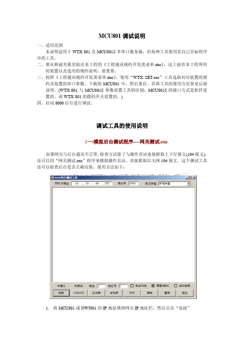
调试工具的使用说明(一)模拟后台测试程序----网关测试.exe如果网关与后台通讯不正常,检查方法除了与操作员站连接抓取上下行报文(104报文),还可以用“网关测试.exe”程序来模拟操作员站,直接抓取以太网104报文。
这个测试工具还可以检查后台是否正确安装。
使用方法如下:1.将MCU801或NWJ801的IP地址填到网关IP地址栏,然后点击“连接”2.连接成功后,点击STARTDT启动连接,将屏蔽U格式打上勾,这样监视到的均为下发及网关上送的104报文。
3.此工具可测试总召唤、召电度、对时等功能,还可以根据报文类型选择要监视的报文(遥测、遥信报文)。
(二)监视串口报文程序----串口监视.exe如果MCU801与装置通讯不正常,可以用“串口监视.exe”程序来监视串口报文。
使用方法如下:1.将MCU801的IP地址填到网关IP地址栏,然后点击“连接”2.“连接”成功后,选择要监视装置所在的“串口”,写入后需要“重启”。
3.再次“连接”即可以监视到网关下发的报文以及装置的回复报文。
(三)MCU801S配置工具----MCU801S_SET.exe与装置通讯,首先要配置串口参数及选择规约,这就要用到“MCU801S_SET.exe”来进行配置。
FM801 主控制器模块使用说明书 B

硬件产品用户手册北京和利时系统工程股份有限公司FM801 主控单元模块目录1.基本说明 (1)1.1 简介 (1)1.2组成 (1)2.原理说明 (2)3.使用说明 (2)3.1前面板说明 (2)3.2状态指示灯说明 (3)3.3接线端子定义 (4)3.4站号设置 (4)3.5安装和固定 (4)3.6 如何连入网络 (5)3.7冗余配置说明 (7)3.8掉电保护设置 (8)3.9手动复位 (8)4.主控单元的维护 (9)5.技术指标 (10)6 与旧型产品的比较 (10)HollySys主控单元FM801主控单元模块1.基本说明1.1 简介FM801型主控单元是MACS系统现场控制站的核心设备,与专用机笼配合使用(如FM300,以下说明均以FM300为例),实现对本站下IO模块数据的采集及运算和接受服务器的组态命令及数据交换。
通过冗余以太网接口把现场控制站的所有数据上传到MACS系统服务器,操作员站/工程师站指令也通过以太网下传到FM801。
1.2组成FM801型主控单元为盒式插件结构,如图1-1所示。
FM801的前面板有状态指示灯、掉电保护开关、复位按钮、电源指示灯;后面板的64针插头插在FM300内的64针插座上,实现与FM300的连接;通信接口、站号设置、电源接口位于机笼FM300的背板上。
图1-1 FM801外观图HollySys 1FM801 主控单元模块2.原理说明FM801接口电路原理框图如图2-1所示。
DP主站接口采用数字信号处理技术(DSP)和高速通用异步收发器(UART)实现DP通讯,DSP与PC/104总线接口采用双口RAM。
静态数据存储器(SRAM)实现掉电保护和重要数据备份功能。
两个以太网接口SENT1、SENT2采用10Base-T(使用RJ45连接器)网络标准,实现与外部(服务器站/操作员站/工程师站)的数据交换,一个以太网接口RNET用于主/从主控单元间的数据备份。
- 1、下载文档前请自行甄别文档内容的完整性,平台不提供额外的编辑、内容补充、找答案等附加服务。
- 2、"仅部分预览"的文档,不可在线预览部分如存在完整性等问题,可反馈申请退款(可完整预览的文档不适用该条件!)。
- 3、如文档侵犯您的权益,请联系客服反馈,我们会尽快为您处理(人工客服工作时间:9:00-18:30)。
ARM801 安装调试指南ARM801型试验机控制器由主控板,键盘,显示驱动板组成,如下图所示,主控板采集力和位移信号,根据试验规程,驱动电机运动,得出要求的结果,该主控板采用ARM系列32位处理器,功能强大,运算速度快,下面将根据信号接线具体说明。
主控板同时连接键盘和显示驱动板,用来接收键盘命令,输出显示信息。
键盘可以是按键键盘,也可以是薄膜键盘液晶显示器能实时显示试验曲线和多个测试结果,可连接多种型号的针打或热敏微型打印机打印试验曲线和试验结果,驱动电机类型繁多,如直流调速器,步进电机,伺服电机,变频器,比例阀等。
既可用于工厂生产车间的恶劣环境也可用于实验室的清洁环境,操作起来快速灵活。
图1 主控板图2 显示驱动板图3 LCD显示屏图5 键盘软薄膜键盘定义// ^ <- 设置标定速度清零试验// V 上升停止下降查询打印复位横式键盘定义为:^ 标定清零试验上升<- 设置复位速度停止V 打印档位查询下降竖式键盘定义为:上升试验^停止清零设置下降复位V速度标定查询档位帮助打印显示驱动板连接液晶显示屏用来输出显示信息,因为液晶显示屏型号众多,引脚定义也不一样,通过更换显示驱动板可以支持任意液晶显示屏,默认使用的液晶显示屏为广东肇庆生产的OCMJ8X15D汉字显示屏,满屏可显示8行15列汉字,或240X128点阵的图形。
这种尺寸的显示屏能满足大多数的显示需要,价格适中,为首选。
显示驱动板通过一10芯扁平电缆插到主控板的10芯LCDPORT接口上。
下面详细介绍主控板上的接口,1个10芯的接口,名字为SPI_LCD,,用来接显示驱动板,1个单排7芯接口,名字为J3,用来插薄膜键盘,另有圆孔,25针接口,每个针的信号定义用户必须准确理解。
圆孔接口为电源输入接口,用来输入12V1A的直流电源,内正外负,如果主控板还为微型打印机供电,则需要12V2A的容量或由外部电源给打印机供电。
内部有防反接电路,接线正确,则旁边的指示灯亮,否则不亮。
25针接口信号的定义为:1-VX1 力传感器电源正对应外接9针的12-IN1+ 力传感器信号正对应外接9针的23-IN1- 力传感器信号负对应外接9针的34-SGND力传感器信号负对应外接9针的4以下其他针对应外接25针的相应引脚5-GND6-XW1 电机限位1输入端,与GND短接表示有信号7-XW2 电机限位2输入端,与GND短接表示有信号8-PUSER_IN 数字输入,接12脚POUT 测电机转动角度9-A10 PWM数字输出,可接直流电机10-PSHINENG 电机使能信号输出11-PFANGXIANG 电机方向信号输出12-POUT 电机驱动脉冲频率输出13-5V 5V电源正输出14-VCC 光电编码器电源正输出不接15-PHA 光电编码器A+16-PHB 光电编码器B+17-GND 光电编码器电源负18-PIN1 数字输入端19-PIN2 数字输入端20-UTX1 接打印机数据输入线21-URX1 接打印机的状态线22-GND 接打印机的地23-UTX0 串口触摸屏24-URX0 串口触摸屏25-+12V 给触摸屏或接近开关或光电开关供电实际应用:1、限位一种情况是使用两个机械行程开关,分别做为上限位和下限位,接线方式为上行程开关的两个常开触点分别接5,6,下行程开关的两个常开触点分别接5,7或者是两个机械行程开关并连,两个常开触点分别接5,6。
另一种情况是使用有源光电或接近开关,光电开关有3个引脚,光电开关的电源正引脚接25,光电开关的电源负引脚接22,光电开关的信号引脚接6或7。
只能使用常开式的光电或接近开关。
附:光电开关的判断,为光电开关加上电源,不动作时信号脚输出高电平,动作时输出低电平为常开型2、微型打印机微型打印机必须外接供电,因为主控板上的5V电源功率不够,信号线由20,21脚引出,微型打印机必须是RS232电平串行接口。
波特率9600,无校验,数据8位,停止位1位。
信号线由20,21,22脚引出控制板←→打印机22 GND ←→GND20 TX ←→RX21 RX ←-→CTS注意不同厂家的打印机指令集不同,接口引脚的定义不同,针式打印机与热敏打印机的指令集不同,定货时请提前说明,默认为荣达公司的热敏汉字打印机。
3、电机控制(直流电机,步进电机,交流伺服,比例阀,变频器驱动感应电机)直流电机和变频器驱动交流感应电机的转速采用模拟电压控制,利用9脚输出模拟电压,分辨率4000,电压范围可调。
3脚PFANGXIANG用来控制转动方向,4脚PSHINENG用来控制使能与禁止。
步进电机和交流伺服电机都采用脉冲频率驱动,12脚POUT 输出频率,11脚PFANGXIANG 用来控制转动方向,10脚PSHINENG 用来控制使能与禁止。
这三个脚能吸收10毫安电流,对于光电隔离的接口,请注意接线的极性。
建议接法如下:光电二极管的阳极接1脚(5V 电压),阴极分别接脉冲,方向,使能。
比例阀通过12脚POUT 输出PWM 脉冲控制试验机操作界面图:测控仪的正面可分为两个部分:液晶显示部分、键盘。
图形如下:液晶显示屏 标定 速度 清零 试验 设置停止 下降 复位↑ ↓ 上升 查询 打印 ←测控仪的正面可分为两个部分:液晶显示部分、键盘。
图形如下:2.3面键各部功能介绍:液晶显示屏:显示力值、峰值, 位移、速度、提示等。
键盘:配合液晶使用,用于控制操作和各参数值的改变,以及控制电机的运行。
2.4各按键介绍:2.4.1名称及功能:[↑]、[↓],[←]两键配合[标定]、[设置]用于选择和修改数据,下面在其他键的功能介绍中穿插进行示例说明。
[设置],按[设置]键将显示液晶显示屏 标定清零 试验 上升 设置 复位速度 停止 ↑ ↓ 打印 切换 查询下降 ←功能选择1.普通拉压试验2.定力值试验3.定位移试验这也是开机后直接进入的状态。
其中第一行反白显示,表示默认的是第一行,按[↑]、[↓]键可在三个选项里变换,选中其中一项后按[设置]键后显示1-试验速度(mm/min) 0060.002-回程速度(mm/min) 0080.003-减速提前位移(mm) 0010.004-加力时移动方向0-下0000005-力单位(N,kN,Kg) 000006-是否用引伸计0-不用00000按设置键确认按复位键保存并退出按上下箭头选择参数项最后两行是操作提示,其中第一行反白显示,表示默认的是第一行,按[↑]、[↓]键可在多个选项里变换,这些选项都是前一步选择所需要的参数,前一步的选择不同,本屏选项的内容和数目也不同。
用[↑]、[↓]键选中某个选项,则该选项反白显示,这时按[设置]键,则该选项内容的最后一位闪烁显示,表示该位可以修改,按[↑]、[↓]键则该位在0-9之间变化,按[←]键则前移一位闪烁显示,该项的内容修改完毕后按[设置]键,则数字停止闪烁,整个参数项继续反白显示,这时按[↑]、[↓]可以选择其他参数项。
当所有的参数修改完毕后按[复位]键,则保存刚才所有的修改并进入到正常试验状态设置参数说明:设置参数共10项或更多项(随功能不同而变),(一、)普通拉压试验时以一定的速度加力直到试样破坏进行试验前,先设置好试验参数,拉簖或压碎自动停机,自动记录最大力,最大强度,最大变形率,还能自动求出屈服强度。
设置参数是:1.试验速度,当按试验键后,横梁以该速度移动加力2.返回速度,拉断或压碎试样后,横梁以该速度返回,0表示试样破裂时横梁不返回3.返回提前减速位移mm,调整次数可使返回时的位置准确。
4.加力式移动方向0-向下,1-向上5.力单位,0->N,1-kN,2->kg6.是否使用引伸计,0为不用7.编号,随着每一次试验,该数自动增大,若重做某一试验,可修改次编号,这样以后的试验就从该编号开始。
开机默认为0,若设为其他值可以查询以前保存的试验结果。
8.试样面积,计算最大强度时用,最大力除以面积等于最大强度9.试样长度,计算变形率用,断裂时的最大变形除以长度等于变形率10.预紧力,以拉弹簧刚丝为例,试样一般不直,若预紧力设为50N,则表示当力为50N时试样变直,从这时开始作为计算变形的起点,一般设为011.破形判断起始力,当大于该力时才进行破形判断12.破形于峰值百分比,默认70,表示当力下降到最大值的70%时认为试样破裂。
13.是否返回,0表示试样破裂时横梁不返回,1表示试样破裂时横梁以返回速度自动返回14.分组数,若小于2,表示不分组,若大于2,表示分组,例如设为3,则当进行3次试验以后,会有提示分组数到达,这时若按查询键查询结果,不紧可以看到每一次的试验结果,还可以看到三次试验结果的平均值。
最大50015.X轴坐标,最大变形。
恰当地设置此数,可以使液晶屏上的试验曲线美观。
一般地,从试验开始到试样破坏,变形有多大这里就填多少,即使填写不合适也对试验结果无影响,只是曲线显示够美观而已。
16.曲线Y轴坐标(N),恰当地设置此数,可以使液晶屏上的试验曲线美观。
一般地,这里可以设的比最大试验力稍微大一些即可。
即使填写不合适也对试验结果无影响。
17.年,打印时用,若为0,不打印日期18.月,打印时用,若为0,不打印日期19.日,打印时用,若为0,不打印日期当试件破坏后,就自动求出了试验结果,试验结果有:最大力值,最大强度,断点变形率(二)、定力值试验以一定的速度加力直到指定力值进行试验前,先设置好试验参数,试验参数有1.试验速度,当按试验键后,横梁以该速度移动加力2.返回速度,拉断或压碎试样后,横梁以该速度返回,0表示试样破裂时横梁不返回。
3.返回提前减速位移mm,调整次数可使返回时的位置准确。
4.加力式移动方向0-向下5.力单位,0->N,1-kN,2->kg6.是否使用引伸计,0为不用7.编号,随着每一次试验,该数自动增大,若重做某一试验,可修改次编号,这样以后的试验就从该编号开始。
开机默认为0,若设为其他值可以查询以前保存的试验结果。
9.预紧力,以拉弹簧刚丝为例,试样一般不直,若预紧力设为50N,则表示当力为50N时试样变直,从这时开始作为计算变形的起点,一般设为09.破形判断起始力,当大于该力时才进行破形判断10.是否返回,0表示试样破裂时横梁不返回,1表示试样破裂时横梁以返回速度自动返回11.分组数,若小于2,表示不分组,若大于2,表示分组,例如设为3,则当进行3次试验以后,会有提示分组数到达,这时若按查询键查询结果,不紧可以看到每一次的试验结果,还可以看到三次试验结果的平均值。
最多50012.X轴坐标,最大变形。
恰当地设置此数,可以使液晶屏上的试验曲线美观。
一般地,从试验开始到试样破坏,变形有多大这里就填多少,即使填写不合适也对试验结果无影响,只是曲线显示够美观而已。
