迪新微电脑数显单门软镜储存柜
SCALANCE X201-3P IRT Managed IE IRT 交换机 6GK5201-3J

compact 90 mm 125 mm 124 mm 1 kg
Yes Yes Yes No
Product properties, functions, components / general
Cascading in the case of a redundant ring / at
50
reconfiguration time of <\~0.3\~s
Product extension / optional / C-PLUG
Yes
Further Information / Internet Links Internet-Link ● to website: Selector SIMATIC NET SELECTION TOOL ● to website: Industrial communication ● to website: Industry Mall ● to website: Information and Download Center ● to website: Image database ● to website: CAx Download Manager ● to website: Industry Online Support
● SICLOCK support
Yes
Protocol / is supported
● NTP
No
● SNTP
Yes
Standards, specifications, approvals Standard ● for FM
● for hazardous zone
● for safety / from CSA and UL ● for hazardous zone / from CSA and UL
内镜储存柜让内镜储存更安全!

内镜储存柜让内镜储存更安全!随着现代医学的发展,内窥镜操作被广泛的应用于临床,也因为它的“微创”深受患者的欢迎。
内镜种类繁多,结构复杂,操作器械贵重而精细。
在日常工作中常因器械存放零乱,难以固定而造成保养不便,取用时易遗漏,甚至因相互碰撞而损伤镜面,严重影响器械的使用年限。
为保证内镜存放得当,不会因碰撞而造成镜面损伤,内镜储存柜内部材料要安全有韧性,内柜设计要光滑无突出,目前比较适合的就是采用PMMA高分子复合材料独立开模,整体吸塑成型。
最好能配有全方位内镜悬挂系统。
该系统一般是采用透明亚克力板制成,分为上、中、下三部分,全方位定位内镜防止相互碰撞,下部分可调节,可根据需要来调整高度。
大量的研究都表明内镜存储不当造成了微生物污染,因此内镜的存放很重要。
胃肠病学护理学会建议内镜存放时应垂直悬挂,远端应自由悬挂在清洁、通风良好、无尘的区域。
存放区通风良好有利于内镜的持续干燥,避免潮气积聚,从而不利于微生物污染的发生。
所以,内镜储存柜除了能让内镜垂直存放,还要有良好的通风。
内镜储存柜内就需要配备循环风系统,时刻保持柜内通风顺畅,干燥无尘。
在《内镜清洗消毒技术规范》中对内镜储存设备要求柜内表面光滑、无缝隙、便于清洗,同时还要具备一定的保持消毒的效果。
普通的内镜储存柜的紫外线灯需每周消毒一次,储镜柜的温度、湿度不能很好的控制,影响消毒效果。
柜内空气消毒时要取出内镜,可能会造成再次污染。
紫外线直接照射内镜可对内镜表面造成损伤,加快内镜的老化,使用前要用2%戊二醛溶液浸泡消毒,这样操作就比较繁琐,工作效率低,同时也可能会造成再次污染。
相较于普通的内镜储存柜,微电脑数显内镜储存柜无论是从储存效果还是对内镜的保养上都要优于普通的内镜储存柜。
内镜储存柜是储存清洗消毒后的内镜的理想的储存设备,能够有效避免内镜洗消后的再污染,某种程度上延长了内镜的使用寿命。
建议医院和各大医疗机构都配备内镜储存柜。
本文档由泰州迪新医疗提供。
D-27 1
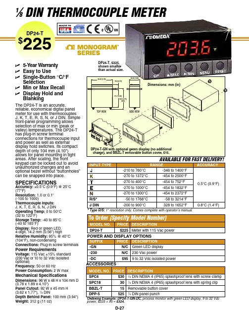
D-271⁄8DIN THERMOCOUPLE METERThe DP24-T is an accurate, reliable, economical digital panel meter for use with thermocouples J, K, T, E, R, S, N, or J DIN. Simple front-panel programming allows selection of max or min (peak or valley) temperatures. The DP24-T has plug-in screw terminalconnections for thermocouple input and power as well as external display hold switches. Its compact depth of only 104 mm (4.10")allows for panel mounting in tight areas. After scaling, the frontkeypad can be locked out to avoidunauthorized changes and anoptional bezel without “buttonholes”can be snapped into place.SPECIFICATIONSAccuracy:±0.5°C (0.9°F) @ 25°C (77°F)Resolution:1.0 or 0.1°(-100 to 1000)Thermocouple Inputs:J, K, T, E, R, S, N, J DIN Operating Temp:0 to 50°C (32 to 122°F)Storage Temp: -40 to 85°C (-40 to 185°F)Display:Red or green LED, 4-digit, 14.2 mm (0.56") highRelative Humidity: 95% @ 40°C (104°F), non-condensingConnections:Plug-in screw terminalsPower RequirementsVoltage: 115 Vac ±15% standard (230 Vac or 10 to 32 Vdc isolated optional)Frequency:50 or 60 HzPower Consumption:2 W maxMechanical SpecificationsDimensions:96 W x 48 H x 104mm D (3.78 x 1.89 x 4.10")Panel Cutout: 92 W x 45 mm H (3.62 x 1.77"), 1⁄8DINDepth Behind Panel:100 mm (3.94")Weight:312 g (11 oz)shown smaller than actual size.power, $225 + 95 = $324.48.00 (1.89)ߜ5-Year Warranty ߜEasy to UseߜSingle-Button °C/°FSelectionߜMin or Max Recall ߜDisplay Hold andBlankingCANADA www.omega.ca Laval(Quebec) 1-800-TC-OMEGA UNITED KINGDOM www. Manchester, England0800-488-488GERMANY www.omega.deDeckenpfronn, Germany************FRANCE www.omega.frGuyancourt, France088-466-342BENELUX www.omega.nl Amstelveen, NL 0800-099-33-44UNITED STATES 1-800-TC-OMEGA Stamford, CT.CZECH REPUBLIC www.omegaeng.cz Karviná, Czech Republic596-311-899TemperatureCalibrators, Connectors, General Test and MeasurementInstruments, Glass Bulb Thermometers, Handheld Instruments for Temperature Measurement, Ice Point References,Indicating Labels, Crayons, Cements and Lacquers, Infrared Temperature Measurement Instruments, Recorders Relative Humidity Measurement Instruments, RTD Probes, Elements and Assemblies, Temperature & Process Meters, Timers and Counters, Temperature and Process Controllers and Power Switching Devices, Thermistor Elements, Probes andAssemblies,Thermocouples Thermowells and Head and Well Assemblies, Transmitters, WirePressure, Strain and ForceDisplacement Transducers, Dynamic Measurement Force Sensors, Instrumentation for Pressure and Strain Measurements, Load Cells, Pressure Gauges, PressureReference Section, Pressure Switches, Pressure Transducers, Proximity Transducers, Regulators,Strain Gages, Torque Transducers, ValvespH and ConductivityConductivity Instrumentation, Dissolved OxygenInstrumentation, Environmental Instrumentation, pH Electrodes and Instruments, Water and Soil Analysis InstrumentationHeatersBand Heaters, Cartridge Heaters, Circulation Heaters, Comfort Heaters, Controllers, Meters and SwitchingDevices, Flexible Heaters, General Test and Measurement Instruments, Heater Hook-up Wire, Heating Cable Systems, Immersion Heaters, Process Air and Duct, Heaters, Radiant Heaters, Strip Heaters, Tubular HeatersFlow and LevelAir Velocity Indicators, Doppler Flowmeters, LevelMeasurement, Magnetic Flowmeters, Mass Flowmeters,Pitot Tubes, Pumps, Rotameters, Turbine and Paddle Wheel Flowmeters, Ultrasonic Flowmeters, Valves, Variable Area Flowmeters, Vortex Shedding FlowmetersData AcquisitionAuto-Dialers and Alarm Monitoring Systems, Communication Products and Converters, Data Acquisition and Analysis Software, Data LoggersPlug-in Cards, Signal Conditioners, USB, RS232, RS485 and Parallel Port Data Acquisition Systems, Wireless Transmitters and Receivers。
RAININ移液器产品目录

量程 0.1μl–2μl 0.5μl–10μl 2μl–20μl 10μl–100μl 20μl–200μl 20μl–300μl 100μl–1000μl 200μl–2000μl 500μl–5000μl 1ml–10ml 移液器套装 SL-START
订货号 17003606 17003609 17003619 17003613 17003622 17007313 17003616 17003624 17003626 17003611 17006694
● 手部重复性劳损(RSI) ● 移液准确性降低 ● 移液操作效率降低
什么原因导致了较大的移液活塞推进力?
传统的移液活塞推进力 4kg
1
2
什么原因导致了退吸头所用的较大手腕力?
传统移液器退吸头所需的手腕力 4kg
1 2
1 吸液弹簧 慢慢压下吸液弹簧, 直到第一个停顿点
2 排液弹簧 下压弹簧到第一个停 顿点,然后继续用力 下压弹簧到第二停顿 点,将液体完全排 出。
LTS多道移液器产品
LTS多道移液器概述.............................................. 14 Pipet-Lite LTS磁辅手动多道移液器..................................16 EDP3-Plus LTS电动多道移液器.....................................17 Pipet-Lite间距可调手动多道移液器................................. 18 EDP3-间距可调电动多道移液器................................... 19
3
传统的移液方式,往往造成操作者的 手部疲劳和重复性劳损(RSI)
内镜清洗消毒工作站及一体化清洗中心设备系统的参数及配置

内镜清洗消毒工作站|一体化清洗中心系统系统的技术参数及配置1、DK-C2000-QXJ 迪康牌内镜全自动清洗消毒机适用范围适用于胃肠镜室、呼吸科、耳鼻喉科,ICU,手术室各类软镜、硬镜的清洗消毒等。
技术参数技术参数::额定电压 220V AC频 率 50Hz 清洗方式高压旋转喷淋 使用水压 0.02-0.8MPa 额定功率600W额定电流 10A 消毒时间 1-3min 制水时间 4-8min 酸化水PH 值 2~3 酸化水电位值≥1100mv 内管道洗消流量 ≥600ml/min 消毒机清洗流量 ≥10L/min有效氯含量 60±10mg/L净 重 52Kg 酸性氧化电位水杀菌机理 细菌、病毒、真菌等微生物的生存环境在PH4-9之间,氧化还原电位ORP 值在-400~+900mv 之间。
在这个范围以外,微生物很难生存和繁殖。
ORP 值决定着微生物的呼吸和代谢。
酸性氧化电位水的杀菌机理是利用其高痒化还原电位(ORP1100mv ),低PH 值(2.7)以下来改变微生物的生存环境,使微生物的细胞膜发生变化,导致细胞膜通透性增强和细胞代谢酶受到破坏而达到杀灭微生物的目的。
酸性氧化电位水生成器安全与卫生标准 201⒈ 1⒉30发布2012-05-01 实施7.1.2 内镜的消毒按《内镜清洗消毒技术操作规范》(2004年版)的要求,用清洁剂和多酶洗液清洗,净水冲洗后浸人酸性氧化电位水,并用专用连接器将酸性氧化电位水出水口与内镜各孔道连接,流动冲洗浸泡消毒3min-5min,净水冲洗30s,取出烘干或用无菌布拭干。
清洗机原理清洗机原理::本机通过可编程微电脑控制器按照五步法或五槽法全浸泡,将初洗、酶洗、次洗、消毒、末洗及吹干实现自动化,一键式完成所有清洗流程,360度全方位喷淋清洗内镜表面,达到对内镜的彻底冲洗消毒,可以达到国家卫生部2004版的消毒技术操作规范要求,全过程仅需12分钟,加强模式为18分钟。
内窥镜消毒储存柜使用说明书及操作规范

内窥镜储存柜内窥镜储存柜内窥镜储存柜((豪华豪华带内胆带内胆带内胆))使用说明书使用说明书及及操作操作规范规范规范一、简介迪康迪康系列内窥镜储存柜主要用于各种物体表面的消毒和已灭菌的手术器械的保存。
内窥镜储存柜主要用于已灭菌的内窥镜的储存, 结构合理、效率高、使用方便。
内窥镜清洗消毒后是否规范存放,直接影响到内窥镜的使用寿命以及下次使用的卫生状况。
我单位根据卫生部《内镜清洗消毒技术操作规范(2004版)》(卫医发100号)第二十六条的要求研发的内窥镜紫外线杀菌储存柜配有多层挂架,确保镜体悬挂、弯角固定钮置于自由位。
可挂多条、多种内镜,并可挂10—20条活检钳。
内装有紫外线消毒灯。
储存柜内表面光滑、无缝隙、便于清洁。
将内窥镜清洗消毒后规范放置在紫外线杀菌储存柜内,是对其使用寿命和卫生状况的有效保证。
二、结构原理、特点及用途1.原理图原理图2.消毒原理和特点消毒原理和特点 DKG-10型内窥镜储存柜主要通过253.7Å强紫外线的光化学作用促使细菌和病毒微生物细胞的裂解、直至死亡。
对柜内的消毒是通过柜内空气循环进出储存柜而对细菌微生物进行杀菌。
3.应用范围应用范围将内窥镜清洗消毒后规范放置在紫外线杀菌储存柜内,是对其使用寿命和卫生状况的有效保证。
适用于医疗机构作为医疗器械表面消毒或已灭菌手术器械的保存用。
紫外线灯管4.杀灭微生物类别杀灭微生物类别金黄色葡萄球菌和大肠杆菌。
杀菌因子5.杀菌因子紫外线。
三、性能指标1.电源 220V 50HZ2.紫外线辐照度 ≥90μW/cm23. 紫外线泄漏 ≤1μW/cm24.安全类型 Ⅰ类B型5.输入功率 300VA6.容积 590升7.保险丝规格 F5A8.外形尺寸 87×55×200cm正常工作条件四、正常工作条件1.环境温度:5℃-40℃2.相对湿度:≤80%3.大气压力:86-106Kpa4.工作电源:交流220V 50HZ5.无腐蚀性气体,易燃易爆气体场合五、使用方法1.安装把储存柜放在干燥、通风良好、无腐蚀性物质的室内,地面水平平整;放置好好,将底部万向轮的刹车固定好,防止柜子走动。
可视软镜招标参数【模板】

可视软镜招标参数一、技术参数1.解决经鼻经口插管及困难气道插管,同时具备给药、给氧、负压吸引等功能2.★配备一体式显示器,像素≥1920(RGB)*4803.显示器左右转动角度不小于0-180°显示屏上下转动角度不小于0-130°。
4.主机具有≥8G内存卡,有拍照、摄像、储存等功能,具有视频输出且兼容AV输出功能5.视野角度:≥ 90°6.插入管:软管直径≤5.2mm,通道≤2.6mm,有效工作长度不小于600㎜7.镜体手柄为非金属医用高分子材料制成,机身轻盈耐腐蚀8.插入管前端先端头由操作手柄控制上下弯曲角度,向上≥160°,向下≥130°9.采用自制高分辨率摄像头,开机不需白平衡即可确保显示效果一致性10.内置全密封防水高功率LED光源,光照度≥700LUX11.镜体手柄配置不可拆卸式气压平衡阀,可随时轻松对镜体测漏12.整机参数:分辨率≥9.92lp/mm,景深:3-100㎜13.整机采用电子成像技术,摄像系统位于插入管前端;采用LED照明光源。
14.整机重量不大于600克,整套设备内置锂电池,位于显示器上,不可插拔拆卸,电池容量≥2200mAH,充满电后可连续工作时间≥2小时;当缺电时,设备直接在主机上充电。
二、商务要求1.交货期:合同签订后期七日内2.售后服务:2.1免费送货至采购方指定地点安装调试(包括设备所匹配的电力等辅助设施安装)2.2免费操作和维保培训2.3质保期:1年2.4维修:质保期内的维修费用全免;提供设备终身维保服务,质保期后的维修只收取零备件费(如有易损件、耗材请一并报价,无则不用)。
接维修通知4小时内到场处理3.质保金:签订合同前供货方向采购方缴纳中标价的10%作为履约保证金,设备验收合格交付使用后自动转为质保金,质保期届满且设备无质量问题全额无息退还4.付款方式:验收合格交付使用之日起三个月期满且设备无质量问题支付合同全款。
迪新不锈钢与304不锈钢的区别

不锈钢与304不锈钢的区别不锈钢:指耐空气、蒸汽、水等弱腐蚀介质和酸、碱、盐等化学浸蚀性介质腐蚀的刚,又称为耐酸刚。
在实际的应用中,常将耐弱腐蚀介质腐蚀的刚称为不锈钢。
不锈钢的耐腐蚀性随含碳量的增加而降低,因此,大多数不锈钢的含碳量均较低,最大不超过1.2%,有些钢的含碳量甚至低于0.03%(如00Cr12)。
不锈钢中的主要合金元素是Cr(铬),只有当Cr含量达到一定值时,钢材有耐蚀性。
因此,不锈钢一般Cr(铬)含量至少为10.5%。
不锈钢中还含有Ni、Ti、N、Nb、Mo、Si、Cu等元素。
304不锈钢:是不锈钢中常见的一种材质,密度7.93g/cm3,业内也叫作18/8不锈钢。
耐高温800℃,具有加工性能好,韧性高的特点,广泛使用于医疗行业。
同时也是一种通用性的不锈钢,它广泛地用于制作要求良好综合性能(耐腐蚀和成型性)的设备和机件。
为了保持不锈钢所固有的耐腐蚀性,刚必须含有18%以上的铬,8%以上的镍含量。
作为一种用途广泛的刚,304不锈钢具有良好的耐蚀性、耐热性、低温强度和机械特性;冲压、弯曲等热加工性好,无热处理硬化现象(使用温度-196℃~800℃)。
在室内环境中使用304不锈钢效果是相当的好。
不锈钢304不锈钢相对于不锈钢而言,304不锈钢的好处:(1)环保卫生:杜绝了红水、蓝绿水和隐患水问题,无异味,无有害物质析出保持水质纯净,无铅对人体健康无害。
(2)耐磨损:表面美观、清洁光亮、长久耐用、无刮痕(3)耐腐蚀:可防止在潮湿腐蚀的环境中,不易生锈。
(4)耐低温:医疗不锈钢水管,龙头角阀不会轻易断裂。
(5)热膨胀性能和保温性能极好:304不锈钢管具有热胀冷缩缓慢,保温性能好。
(6)权威认证:不锈钢金属元素的析出量比WHO和欧洲饮水用法规定标准值的5%还要低。
泰州市高港区迪新医用设备有限公司成立于1998年,是专业医疗器械生产厂家,主要经营304不锈钢内镜清洗装置,304不锈钢洗手池、304不锈钢内镜储存柜,304不锈钢超声波清洗机等。
ICP DAS ZT-2005-C8用户手册说明书

ZT-2005-C8User Manual WarrantyAll products manufactured by ICP DAS are under warranty regardingdefective materials for a period of one year, beginning from the date ofdelivery to the original purchaser.WarningICP DAS assumes no liability for any damage resulting from the use of thisproduct. ICP DAS reserves the right to change this manual at any timewithout notice. The information furnished by ICP DAS is believed to beaccurate and reliable. However, no responsibility is assumed by ICP DASfor its use, nor for any infringements of patents or other rights of thirdparties resulting from its use.CopyrightCopyright © 2013 by ICP DAS. All rights are reserved. TrademarksNames are used for identification purposes only and may be registeredtrademarks of their respective companies.Technical SupportTable of Contents1Inftroduction (5)1.1Introduction to ZigBee (5)1.2Introduction to the ZT-2005-C8 (6)2Hardware Information (7)2.1Specifications (7)Specifcaions of ZigBee (7)Specifcaions of ZT-2005-C8 module (7)2.2Pin assignments (9)ZT-2005-C8 (9)3Setting up the ZT-2005-C8 (10)3.1Introction to the Configuration Parameters (10)3.2Introduction to the Rotary and DIP Switches (11)3.3Starting the ZT-2005-C8 (13)3.4Examples (14)3.5Communications Testing (15)4 Format, Type and Calibration (16)4.1Over/Under Range Readings (16)4.2Configuration Tables (16)4.3Type code and Data Format Table (17)4.4Calibration (17)5 The DCON/Modbus RTU Command Sets (18)5.1Communication with the ZT-2005-C8 module (18)5.2The DCON Protocol Command Set (18)5.2.1Checksum (19)5.2.2Overview of the DCON Command Set (20)5.2.3%AANNTTCCFF (21)5.2.4#AA (22)5.2.5#AAN (23)5.2.6$AA0Ci (24)5.2.7$AA1Ci (25)5.2.8$AA0 (26)5.2.9$AA1 (27)5.2.10$AA2 (28)5.2.11$AA5VV (29)5.2.12$AA6 (30)5.2.13$AAF (31)5.2.14$AAM (32)5.2.15$AAP (33)5.2.16$AAS1 (34)5.2.17~AAD (35)5.2.18~AADT (36)5.2.19~AAEV (37)5.2.20~AARE (38)5.2.21@AAA2CiToo (39)5.2.22@AAA3Ci (40)5.3Modbus RTU Protocol (41)5.3.1Modbus Address Mapping (42)5.3.2Function 01(0x01)-Read Coils (43)5.3.3Function 02(0x02)-Read Discrete Inputs (44)5.3.4Function 03(0x03)–Read Multiple Registers (45)5.3.5Function 04(0x04)–Read Multiple Input Registers (46)5.3.6Fuction 05(0x05)–Write Single Coil (47)5.3.7Function 06(0x06)–Write Single Register (48)5.3.8Function 15(0x0F)–Write Multiple Coils (49)5.3.9Function 16(0x10)–Write Multiple Registers (50)5.3.10Function 70(0x46)–Read/Write Module Setting (51)5.3.10.1Sub-function 00(0x00)-Read Module Name (52)5.3.10.2Sub-function 04(0x04)-Write Module Address (53)5.3.10.3Sub-function 05(0x05)-Read the communication setting (54)5.3.10.4Sub-function 32(0x20)-Read Module Firmware Version (55)5.3.10.5Sub-function 37(0x25)-Read The Enabled/Disable status of Channels (56)5.3.10.6Sub-function 38(0x26)-Write The Enabled/Disable status of Channels (57)6Troubleshooting (58)7 Appendix (59)7.1LED Display Status (59)7.2The Extension to the Software Address (59)What ’s in the Shipping Package? The shipping package contains the following items:More Information⏹ Documentation :CD: \Napdos\ZigBee\ZT_Series\Document /pub/cd/usbcd/napdos/zigbee/zt_series/document ⏹ Software :CD: \Napdos\ZigBee\ZT_Series\Utility /pub/cd/usbcd/napdos/zigbee/zt_series/utilityAntenna (ANT-124-05) Quick StartZT-2005-C8module Thermistor (CA-021) CD1Inftroduction1.1Introduction to ZigBeeZigBee is a specification for a suite of high-level communication protocols using small, low-power digital radios based on the IEEE 802.15.4 standard for personal area networks. ZigBee devices are often used in mesh network form to transmit data over longer distances, passing data through intermediate devices to reach more distant ones. This allows ZigBee networks to be formed ad-hoc, with no centralized control or high-power transmitter/receiver able to reach all of the devices. Any ZigBee device can be tasked with running the network.ZigBee is targeted at applications that require a low data rate, long battery life, and secure networking. ZigBee has a defined rate of 250 kbit/s, best suited for periodic or intermittent data or a single signal transmission from a sensor or input device. Applications include wireless light switches, electrical meters within-home-displays, traffic management systems, and other consumer and industrial equipment that requires short-range wireless transfer of data at relatively low rates. The technology defined by the ZigBee specification is intended to be simpler and less expensive than other WPANs.1.2Introduction to the ZT-2005-C8The ZT-2005-C8 is an 8 channel thermistor input module, it can monitor the resistance change of thermistor to get temperatue.The ZT-2005-C8 is a wireless ZigBee module, it need to communicate with ZigBee coordinator. The information of ZigBee coordinator can refer ZT-2550 or ZT-2570. Otherwise, users can use rotary switch and DIP switch to set address (or ZigBee Node ID, NID) of module, protocol, DCON checksum, ZigBee RF Power, ZigBee Pan ID (PID), and ZigBee channel.2Hardware Information 2.1Specifications2.2Pin assignments ZT-2005-C83Setting up the ZT-2005-C83.1 Introction to the Configuration Parameters1. Pan ID :“Pan ID” parameter is the group identity for a ZigBee network, and mustthe same for all devices in the same ZigBee network. (The range are 0 to 1, 0x0000~0x0001)2. Address/Node ID :“Address /Node ID” parameter is the individed identity of aspecific the ZigBee module, and must be unique for each device connected the same ZigBee network. (The range are 1 to 247,0x0001~0x00F7)3. RF Channel : “RF Channel” parameter indicates the radio frequency channel,RF channels 0x04, 0x09, 0x0E or 0x0F are recommended because they do not overlap with the Wi-Fi frequency band.4. Protocol/Application Mode :When implementing custom programs based on3.2Introduction to the Rotary and DIP SwitchesThe configuration of the ZT-2005-C8 can be adjusted using a combination of the external rotary switch and the DIP switches. The ZT-2005-C8 device should only be rebooted once the configuration is complete.DIP and rotary switch of ZT-2005-C8Address LSB(Node ID) (Node ID)Rotary SwitchAddress SW※Once the address of hardware switch is set to 0x00, it mens the address is usingsoftware configurations. Refer Sec. 7.2 for more detailed information.3.3Starting the ZT-2005-C8As the ZigBee network is controlled by the ZigBee Coordinator, theZT-2550/ZT-2570 (ZigBee Coordinator) must be configured first. Refer to the documents section below for full details of how to configure these devices.Once configuration of the ZigBee Coordinator has been completed, set the “ZB PID” and “ZB Channel” values for the ZT-2000 I/O device to the same values as the network, and then reboot the device. The module will automatically start to function on the ZigBee network using the default protocol.※ Documents:/pub/cd/usbcd/napdos/zigbee/zt_series/document/zt-255x/ /pub/cd/usbcd/napdos/zigbee/zt_series/document/zt-257x/※ Configuration Utility (Used to configure ZigBee Coordinator):/pub/cd/usbcd/napdos/zigbee/zt_series/utility/3.4 ExamplesConfigurations of ZT-2550/ZT-2570Configuration of ZT-2005-C8DIP SwitchTransparent mode3.5Communications TestingOnce the ZT-2005-C8 module has joined the ZigBee network, the signal quality can be comfirmed by monitoring the status of the ZigBee Net LED indicators. If the LED indicator shows a steady light, communication with the ZT-2005-C8 module has been successfully established for data acquisition and control.ICP DAS also provides the “DCON Utility”, which can be used to simulate DCON/Modbus communication. This software can also be used to verify the device settings and ZT-2005-C8 functions.The DCON Utility Pro can be download from:/pub/cd/8000cd/napdos/driver/dcon_utility/Simulating I/O channel via the DCON Utility Prounch the DCON Utility and select the appropriate COM Port settings to connectto the ZigBee Coordinator (ZT-2550/ZT-2570).2.Click the “Search” button to start searching for ZT-2005-C8 modules connectedto the same ZigBee network.3.If any ZT-2005-C8 modules are found, they will be displayed in the device listwindow. Double-click the list of the module name to start the platform to operate the I/O channels.4Format, Type and Calibration 4.14.2Configuration Tables4.4CalibrationWarning: Performing calibration is not recommended until the process is fully understood.The calibration proceduce is as follows:1.Warm up the module for at last 30 minutes.2.Enable calibration. (Refer to Section 5.2.22.)3.Connect the zero calibration resistor.4.Send the zero calibration command. (Refer to Section5.2.6)5.Connect the span calibration resistor.6.Send the span calibration command. (Refer to Section 5.2.7)7.Repeat steps 2 to 6 three times.5 The DCON/Modbus RTU Command Sets 5.1Communication with the ZT-2005-C8 moduleZT-2005-C8 module can be operated using either the DCON or the Modbus RTU protocol, which can be selected by adjusting the position of DIP Switch 2 to OFF (DCON) or ON (Modbus RTU) and then rebooting the ZT-2005-C8 to use the new protocol.5.2The DCON Protocol Command SetThe ZT-2005-C8 are controlled via wireless broadcast commands, so each device must have a unique address (or Node ID) that is saved in the EEPROM of the device.Consequently, all command and response formats contain the address of the destination module. When an I/O device receives a command, it will determine whether or not to respond based on the address contained in the command.※Note: ‘CR’ (0x0D) is the end of command (carriage return) character used to end a frame, and all characters should be expressed in capital letters.5.2.1ChecksumCalculation the Checksum:Sum the ASCII codes of all the characters contained in the command in addition to the ‘CR’ terminator. The Checksum is the sum value expressed inHexadecimal format.Example: Command ”$012(CR)”Sum = ‘$’ + ‘0’ + ‘1’ + ‘2’ = 24h + 30h + 31h + 32h = B7hChecksum = “B7”DCON Command with Checksum =“$012B7(CR)”Example: Response ”!01200600(CR)”Sum = ‘!’ + ‘0’ + ‘1’ + ‘2’ + ‘0’ + ‘0’ + ‘6’ + ‘0’ + ‘0’= 21h+30h+31h+32h+30h+30h+36h+30h+30h= 1AAhChecksum = “AA”DCON Response with Checksum = “!01200600AA(CR)”※Note: The Checksum is the sum value expressed in capital letters.5.2.2Overview of the DCON Command SetGeneral Command SetCommand Response Description Section %AANNTTCCFF !AA Sets the Configuration of the Module 5.2.35.2.4 #AA >(Data) Reads the Analog Input Data from allChannels5.2.5 #AAN >(Data) Reads the Analog Input Data from aSpecific Channel5.2.6 $AA0Ci !AA Performs an Analog Input Zero Calibrationof a Specific Channel on the Module5.2.7 $AA1Ci !AA Performs an Analog Input Span Calibrationof a Specific Channel on the Module5.2.8 $AA0 !AA Performs an Analog Input Span Calibrationon the Module5.2.9 $AA1 !AA Performs an Analog Input Zero Calibrationon the Module$AA2 !AATTCCFF Reads the Configuration of the Module 5.2.105.2.11 $AA5VV !AA Enables or Disables Specific Analog InputChannels5.2.12 $AA6 !AAVV Reads whether each Analog Input Channelis Enabled or Disabled$AAF !AA(Data) Reads the Firmware Version of the Module 5.2.13 $AAM !AA(Data) Reads the Name of the Module 5.2.14 $AAP !AASC Reads the communication protocol 5.2.15 $AAS1 !AA Reloads the Default Calibration Parameters 5.2.16 ~AAD !AAT Reads the temperature scaling 5.2.175.2.18 ~AADT !AA Sets the temperature scaling to either °Cor °F~AAEV !AA Enables/Disables calibration 5.2.19 ~AARE !AAsc Read RF Encryption Setting 5.2.205.2.21 @AAA2CiToo !AA Sets the temperature offset of achannel5.2.22 @AAA3Ci !AA Reads the temperature offset ofa channel※Effect after reboot, and Related Commands: $AA2※Related Commands: $AA1Ci、~AAEV※Related Commands: $AA0Ci、~AAEV※Related Commands: $AA1、~AAEV※Related Commands: $AA0、~AAEV※Related Commands: %AANNTTCCFF※Related Commands: $AA6※Related Commands: $AA5VVenable or disable encryption AES 128 encryption automatically, so users don’t need to set again.※Related Commands:@AAA3Ci5.3Modbus RTU ProtocolThe Modbus protocol was originally developed for Modicon controllers by Modicon Inc. Detailed information related to the Modbus RTU protocol can be found at for more valuable information.The Modbus RTU functions of ZT-2005-C8 module are supported as bellow.If the function specified in the message is not supported, then the module responds as below. Note that the address mapping for the Modbus protocol isBase 0.5.3.1Modbus Address Mapping5.3.5Function 04(0x04)–Read Multiple Input。
科勒Simple Smart镜柜 附体脂秤 说明书

© Copyright Kohler China Investment Co., Ltd. 2021© 版权为科勒(中国)投资有限公司所有 2021请仔细阅读本说明书,以便熟悉所需的应用程序的安装、设置以及操作说明。
本说明书中所使用的插图为示意图,可能与您所购买的产品略有不同,请以实际产品为准。
有关本镜柜的安装方法,请先阅读本产品的《安装说明书》。
本说明书基于以下版本制作。
1)科勒云境应用程序1.5.02) Android 系统:7.03) 镜柜Launcher:1.0.7软件版本在持续更新中,软件界面可能因版本不同而有所差异,请以最新软件界面为准。
认识一下科勒新维乐智讯镜柜/镜子主页使用说明镜柜初始化设置镜柜设置使用说明使用体重秤健康管理添加备忘录和交通路线添加家庭成员0406070708080909• KOHLER Konnect ®和科勒®是科勒公司的商标。
• Android是Google LLC的商标。
• iPhone是Apple Inc.的商标。
• QR code是DENSO WAVE INCORPORATED的注册商标。
• 带有Bluetooth®字样的标志和标识是Bluetooth SIG, Inc.的注册商标。
• 本说明书中的其他公司或者产品的名称可能是相应公司的商标或注册商标。
商标注意:新维乐智讯镜柜/镜子中的显示内容,实际位于整个镜柜的右侧镜面上,下列步骤中所涉及到镜柜显示内容的图片都是示意图。
系统支持:· 苹果手机: iOS 11.3.1 或更高版本· 安卓手机:Android 5.1.1 或更高版本步骤3:请通过手机扫描以下二维码, 下载安装科勒云境APP并注册科勒账号。
步骤1:准备配网环境请确保手机接入的WIFI为2.4G频段,名称和密码只包含英文大小写字母、数字、空格、“-“和”_”,且产品所在位置和路由器之间信号稳定,没有承重墙之类的阻隔。
Friulinox设备说明

型号介绍前缀数字BC 急速冷藏051 5盘GN1/1 BF 急速冷冻122 12盘GN2/1200 20盘GN1/1订货编号型号CODE MODELBC051DFBC051AFBF051DFBF051AFBC081AFBF081AFBC121DFBC121AFBF121DFBF121AFBC122DFBC122AFBF122DFBF122AFBC161DFBC161AFBF161DFBF161AF备注:1、此价格为市场销售指导价2、此价格有效期为:2010年1月1日~2010年12月31日后缀A 大容量 F Fast系类D 小容量盘GN1/1产品介绍DESCRIPTION急速冷藏柜(小容量)尺寸:790x700x850H mm产地:意大利电功率:0.91kW VAC230VN 50Hz从+90℃降至+3℃(90分钟) 12kg净重:100kg外部及内部均为AISI 304 18/10不锈钢制作含方便清洁和拆卸的不锈钢支架无须借助工具,液晶显示屏及电子触摸面板配有中心温度探针,自动除霜及冷凝物蒸发节能环保控制面板操作简便,在一个冷冻环节结束后,可储存程序,以便下次使用时再次调出在一个循环结束后,冷冻自动跳到恒温模式已配制冷系统急速冷藏柜(大容量)尺寸:790x700x850H mm产地:意大利电功率:1.13kW VAC230VN 50Hz从+90℃降至+3℃(90分钟) 18kg净重:106kg外部及内部均为AISI 304 18/10不锈钢制作含方便清洁和拆卸的不锈钢支架无须借助工具,液晶显示屏及电子触摸面板配有中心温度探针,自动除霜及冷凝物蒸发节能环保控制面板操作简便,在一个冷冻环节结束后,可储存程序,以便下次使用时再次调出在一个循环结束后,冷冻自动跳到恒温模式已配制冷系统急速冷冻柜(小容量)尺寸:790x700x850H mm产地:意大利电功率:1.2kW VAC230VN 50Hz从+90℃降至+3℃(90分钟) 12kg从+90℃降至-18℃(240分钟) 8kg净重:103kg外部及内部均为AISI 304 18/10不锈钢制作含方便清洁和拆卸的不锈钢支架无须借助工具,液晶显示屏及电子触摸面板配有中心温度探针,自动除霜及冷凝物蒸发节能环保控制面板操作简便,在一个冷冻环节结束后,可储存程序,以便下次使用时再次调出在一个循环结束后,冷冻自动跳到恒温模式已配制冷系统急速冷冻柜(大容量)尺寸:790x700x850H mm产地:意大利电功率:1.35kW VAC230VN 50Hz从+90℃降至+3℃(90分钟) 18kg从+90℃降至-18℃(240分钟) 12kg净重:109kg外部及内部均为AISI 304 18/10不锈钢制作含方便清洁和拆卸的不锈钢支架无须借助工具,液晶显示屏及电子触摸面板配有中心温度探针,自动除霜及冷凝物蒸发节能环保控制面板操作简便,在一个冷冻环节结束后,可储存程序,以便下次使用时再次调出在一个循环结束后,冷冻自动跳到恒温模式已配制冷系统急速冷藏柜(大容量)尺寸:790x700x1320H mm产地:意大利电功率:1.5kW VAC230VN 50Hz从+90℃降至+3℃(90分钟) 25kg净重:138kg外部及内部均为AISI 304 18/10不锈钢制作含方便清洁和拆卸的不锈钢支架无须借助工具,液晶显示屏及电子触摸面板配有中心温度探针,自动除霜及冷凝物蒸发节能环保控制面板操作简便,在一个冷冻环节结束后,可储存程序,以便下次使用时再次调出在一个循环结束后,冷冻自动跳到恒温模式已配制冷系统急速冷冻柜(大容量)尺寸:790x700x1320H mm产地:意大利电功率:2kW VAC230VN 50Hz从+90℃降至+3℃(90分钟) 25kg从+90℃降至-18℃(240分钟) 16kg净重:142kg外部及内部均为AISI 304 18/10不锈钢制作含方便清洁和拆卸的不锈钢支架无须借助工具,液晶显示屏及电子触摸面板配有中心温度探针,自动除霜及冷凝物蒸发节能环保控制面板操作简便,在一个冷冻环节结束后,可储存程序,以便下次使用时再次调出在一个循环结束后,冷冻自动跳到恒温模式已配制冷系统急速冷藏柜(小容量)尺寸:790x800x1800H mm产地:意大利电功率:1.5kW VAC230VN 50Hz从+90℃降至+3℃(90分钟) 25kg净重:170kg外部及内部均为AISI 304 18/10不锈钢制作含方便清洁和拆卸的不锈钢支架无须借助工具,液晶显示屏及电子触摸面板配有中心温度探针,自动除霜及冷凝物蒸发节能环保控制面板操作简便,在一个冷冻环节结束后,可储存程序,以便下次使用时再次调出在一个循环结束后,冷冻自动跳到恒温模式已配制冷系统急速冷藏柜(大容量)尺寸:790x800x1800H mm产地:意大利电功率:2.1kW VAC400V 3N 50Hz从+90℃降至+3℃(90分钟) 36kg净重:182kg外部及内部均为AISI 304 18/10不锈钢制作含方便清洁和拆卸的不锈钢支架无须借助工具,液晶显示屏及电子触摸面板配有中心温度探针,自动除霜及冷凝物蒸发节能环保控制面板操作简便,在一个冷冻环节结束后,可储存程序,以便下次使用时再次调出在一个循环结束后,冷冻自动跳到恒温模式已配制冷系统急速冷冻柜(小容量)尺寸:790x800x1800H mm产地:意大利电功率:2kW VAC230VN 50Hz从+90℃降至+3℃(90分钟) 25kg从+90℃降至-18℃(240分钟) 16kg净重:176kg外部及内部均为AISI 304 18/10不锈钢制作含方便清洁和拆卸的不锈钢支架无须借助工具,液晶显示屏及电子触摸面板配有中心温度探针,自动除霜及冷凝物蒸发节能环保控制面板操作简便,在一个冷冻环节结束后,可储存程序,以便下次使用时再次调出在一个循环结束后,冷冻自动跳到恒温模式已配制冷系统急速冷冻柜(大容量)尺寸:790x800x1800H mm产地:意大利电功率:3.5kW VAC400V 3N 50Hz从+90℃降至+3℃(90分钟) 36kg从+90℃降至-18℃(240分钟) 24kg净重:188kg外部及内部均为AISI 304 18/10不锈钢制作含方便清洁和拆卸的不锈钢支架无须借助工具,液晶显示屏及电子触摸面板配有中心温度探针,自动除霜及冷凝物蒸发节能环保控制面板操作简便,在一个冷冻环节结束后,可储存程序,以便下次使用时再次调出在一个循环结束后,冷冻自动跳到恒温模式已配制冷系统急速冷藏柜(小容量)尺寸:1100x880x1800H mm产地:意大利电功率:3kW VAC400V 3N 50Hz从+90℃降至+3℃(90分钟) 50kg净重:230kg外部及内部均为AISI 304 18/10不锈钢制作含方便清洁和拆卸的不锈钢支架无须借助工具,液晶显示屏及电子触摸面板配有中心温度探针,自动除霜及冷凝物蒸发节能环保控制面板操作简便,在一个冷冻环节结束后,可储存程序,以便下次使用时再次调出在一个循环结束后,冷冻自动跳到恒温模式已配制冷系统急速冷藏柜(大容量)尺寸:1100x880x1800H mm产地:意大利电功率:3.95kW VAC400V 3N 50Hz从+90℃降至+3℃(90分钟) 72kg净重:248kg外部及内部均为AISI 304 18/10不锈钢制作含方便清洁和拆卸的不锈钢支架无须借助工具,液晶显示屏及电子触摸面板配有中心温度探针,自动除霜及冷凝物蒸发节能环保控制面板操作简便,在一个冷冻环节结束后,可储存程序,以便下次使用时再次调出在一个循环结束后,冷冻自动跳到恒温模式已配制冷系统急速冷冻柜(小容量)尺寸:1100x880x1800H mm产地:意大利电功率:4.5kW VAC400V 3N 50Hz从+90℃降至+3℃(90分钟) 50kg从+90℃降至-18℃(240分钟) 32kg净重:239kg外部及内部均为AISI 304 18/10不锈钢制作含方便清洁和拆卸的不锈钢支架无须借助工具,液晶显示屏及电子触摸面板配有中心温度探针,自动除霜及冷凝物蒸发节能环保控制面板操作简便,在一个冷冻环节结束后,可储存程序,以便下次使用时再次调出在一个循环结束后,冷冻自动跳到恒温模式已配制冷系统急速冷冻柜尺寸:1100x880x1800H mm产地:意大利电功率:6.12kW VAC400V 3N 50Hz从+90℃降至+3℃(90分钟) 72kg从+90℃降至-18℃(240分钟) 48kg净重:257kg外部及内部均为AISI 304 18/10不锈钢制作含方便清洁和拆卸的不锈钢支架无须借助工具,液晶显示屏及电子触摸面板配有中心温度探针,自动除霜及冷凝物蒸发节能环保控制面板操作简便,在一个冷冻环节结束后,可储存程序,以便下次使用时再次调出在一个循环结束后,冷冻自动跳到恒温模式已配制冷系统急速冷藏柜(小容量)尺寸:790x800x1950H mm产地:意大利电功率:2.17kW VAC400V 3N 50Hz从+90℃降至+3℃(90分钟) 36kg净重:200kg外部及内部均为AISI 304 18/10不锈钢制作含方便清洁和拆卸的不锈钢支架无须借助工具,液晶显示屏及电子触摸面板配有中心温度探针,自动除霜及冷凝物蒸发节能环保控制面板操作简便,在一个冷冻环节结束后,可储存程序,以便下次使用时再次调出在一个循环结束后,冷冻自动跳到恒温模式已配制冷系统急速冷藏柜(大容量)尺寸:790x800x1950H mm产地:意大利电功率:3.3kW VAC400V 3N 50Hz从+90℃降至+3℃(90分钟) 55kg净重:214kg外部及内部均为AISI 304 18/10不锈钢制作含方便清洁和拆卸的不锈钢支架无须借助工具,液晶显示屏及电子触摸面板配有中心温度探针,自动除霜及冷凝物蒸发节能环保控制面板操作简便,在一个冷冻环节结束后,可储存程序,以便下次使用时再次调出在一个循环结束后,冷冻自动跳到恒温模式已配制冷系统急速冷冻柜(小容量)尺寸:790x800x1950H mm产地:意大利电功率:3.5kW VAC400V 3N 50Hz从+90℃降至+3℃(90分钟) 36kg从+90℃降至-18℃(240分钟) 24kg净重:207kg外部及内部均为AISI 304 18/10不锈钢制作含方便清洁和拆卸的不锈钢支架无须借助工具,液晶显示屏及电子触摸面板配有中心温度探针,自动除霜及冷凝物蒸发节能环保控制面板操作简便,在一个冷冻环节结束后,可储存程序,以便下次使用时再次调出在一个循环结束后,冷冻自动跳到恒温模式已配制冷系统急速冷冻柜(大容量)尺寸:790x800x1950H mm产地:意大利电功率:5.15kW VAC400V 3N 50Hz从+90℃降至+3℃(90分钟) 55kg从+90℃降至-18℃(240分钟) 36kg净重:221kg外部及内部均为AISI 304 18/10不锈钢制作含方便清洁和拆卸的不锈钢支架无须借助工具,液晶显示屏及电子触摸面板配有中心温度探针,自动除霜及冷凝物蒸发节能环保控制面板操作简便,在一个冷冻环节结束后,可储存程序,以便下次使用时再次调出在一个循环结束后,冷冻自动跳到恒温模式已配制冷系统1日~2010年12月31日。
BCD-200KK20E76TI说明书

BCD-200KK20E76TI说明书
基本参数
产品类别双开门
总容积198L
冷藏室容积123L
冷冻室容积75L
温控方式电脑温控
制冷方式直冷
制冷能力17kg/24h
气候类型SN-ST
显示屏LED显示屏
额定耗电量0.57度/天
其他
外形设计银色
外形尺寸640×590×1600mm
其他功能把手形状宽门
冷藏温度可调
控制面板LED触控屏动态冷却
冷藏室关闭功能
制冷循环双
速冷/速冻功能冰箱附件
包装清单冰箱x1 冰块盒x1 说明书x1 合格证x1 保修卡x1
保修信息
保修政策全国联保,享受三包服务质保时间1年
质保备注整机1年,主要部件3年客服电话
电话备注24小时电话服务
详细内容三包有效期自开具发票之日起计算,扣除因修理占用和无零配件待修的时间。
三包有效期内消费者凭发票及三包凭证办理修理、换货、退货。
产品自售出之日起7日内,发生性能故障,消费者可以选择退货、换货或修理。
退货时,销售者应当按发票价格一次退清货款,然后依法向生产者、供货者追偿或者按购销合同办理。
包修凭证为购机发票和服务金卡。
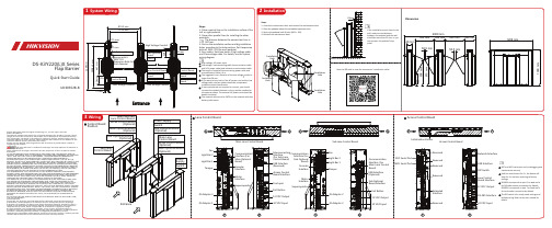
DS-K3Y220(L)X系列闸门屏障快速入门指南说明书
DS-K3Y220(L)X SeriesFlap BarrierQuick Start GuideUD30352B-B©2022Hangzhou Hikvision Digital Technology Co.,Ltd.All rights reserved.About this ManualThe Manual includes instructions for using and managing the Product.Pictures,charts, images and all other information hereinafter are for description and explanation only. The information contained in the Manual is subject to change,without notice,due to firmware updates or other reasons.Please find the latest version of this Manual at the Hikvision website(https:///).Please use this Manual with the guidance and assistance of professionals trained in supporting the Product.Trademarksand other Hikvision’s trademarks and logos are the properties of Hikvision in various jurisdictions.Other trademarks and logos mentioned are the properties of their respective owners. DisclaimerTO THE MAXIMUM EXTENT PERMITTED BY APPLICABLE LAW,THIS MANUAL AND THE PRODUCT DESCRIBED,WITH ITS HARDWARE,SOFTWARE AND FIRMWARE,ARE PROVIDED “AS IS”AND“WITH ALL FAULTS AND ERRORS”.HIKVISION MAKES NO WARRANTIES, EXPRESS OR IMPLIED,INCLUDING WITHOUT LIMITATION,MERCHANTABILITY, SATISFACTORY QUALITY,OR FITNESS FOR A PARTICULAR PURPOSE.THE USE OF THE PRODUCT BY YOU IS AT YOUR OWN RISK.IN NO EVENT WILL HIKVISION BE LIABLE TO YOU FOR ANY SPECIAL,CONSEQUENTIAL,INCIDENTAL,OR INDIRECT DAMAGES,INCLUDING, AMONG OTHERS,DAMAGES FOR LOSS OF BUSINESS PROFITS,BUSINESS INTERRUPTION, OR LOSS OF DATA,CORRUPTION OF SYSTEMS,OR LOSS OF DOCUMENTATION,WHETHER BASED ON BREACH OF CONTRACT,TORT(INCLUDING NEGLIGENCE),PRODUCT LIABILITY, OR OTHERWISE,IN CONNECTION WITH THE USE OF THE PRODUCT,EVEN IF HIKVISION HAS BEEN ADVISED OF THE POSSIBILITY OF SUCH DAMAGES OR LOSS.YOU ACKNOWLEDGE THAT THE NATURE OF THE INTERNET PROVIDES FOR INHERENT SECURITY RISKS,AND HIKVISION SHALL NOT TAKE ANY RESPONSIBILITIES FOR ABNORMAL OPERATION,PRIVACY LEAKAGE OR OTHER DAMAGES RESULTING FROM CYBER-ATTACK, HACKER ATTACK,VIRUS INFECTION,OR OTHER INTERNET SECURITY RISKS;HOWEVER, HIKVISION WILL PROVIDE TIMELY TECHNICAL SUPPORT IF REQUIRED.YOU AGREE TO USE THIS PRODUCT IN COMPLIANCE WITH ALL APPLICABLE LAWS,AND YOU ARE SOLELY RESPONSIBLE FOR ENSURING THAT YOUR USE CONFORMS TO THE APPLICABLE LAW.ESPECIALLY,YOU ARE RESPONSIBLE,FOR USING THIS PRODUCT IN A MANNER THAT DOES NOT INFRINGE ON THE RIGHTS OF THIRD PARTIES,INCLUDING WITHOUT LIMITATION,RIGHTS OF PUBLICITY,INTELLECTUAL PROPERTY RIGHTS,OR DATA PROTECTION AND OTHER PRIVACY RIGHTS.YOU SHALL NOT USE THIS PRODUCT FOR ANY PROHIBITED END-USES,INCLUDING THE DEVELOPMENT OR PRODUCTION OF WEAPONS OF MASS DESTRUCTION,THE DEVELOPMENT OR PRODUCTION OF CHEMICAL OR BIOLOGICAL WEAPONS,ANY ACTIVITIES IN THE CONTEXT RELATED TO ANY NUCLEAR EXPLOSIVE OR UNSAFE NUCLEAR FUEL-CYCLE,OR IN SUPPORT OF HUMAN RIGHTS ABUSES.IN THE EVENT OF ANY CONFLICTS BETWEEN THIS MANUAL AND THE APPLICABLE LAW, THE LATTER PREVAILS.Data ProtectionDuring the use of device,personal data will be collected,stored and processed.To protect data,the development of Hikvision devices incorporates privacy by design principles.For example,for device with facial recognition features,biometrics data is stored in your device with encryption method;for fingerprint device,only fingerprint template will be saved,which is impossible to reconstruct a fingerprint image.As data controller,you are advised to collect,store,process and transfer data in accordance with the applicable data protection laws and regulations,including without limitation,conducting security controls to safeguard personal data,such as, implementing reasonable administrative and physical security controls,conduct periodic reviews and assessments of the effectiveness of your security controls.If thewall,3.SlotholesboltswiringHighLowandSOCmaintenanceRegulatory InformationFCC InformationPlease take attention that changes or modification not expressly approved by the party responsible for compliance could void the user’s authority to operate the equipment.FCC compliance:This equipment has been tested and found to comply with the limits for a Class B digital device,pursuant to part 15of the FCC Rules.These limits are designed to provide reasonable protection against harmful interference in a residential installation.This equipment generates,uses and can radiate radio frequency energy and,if notinstalled and used in accordance with the instructions,may cause harmful interference to radio communications.However,there is no guarantee that interference will not occur in a particular installation.If this equipment does cause harmful interference to radio or television reception,which can be determined by turning the equipment off and on,the user is encouraged to try to correct the interference by one or more of the following measures:—Reorient or relocate the receiving antenna.—Increase the separation between the equipment and receiver.—Connect the equipment into an outlet on a circuit different from that to which the receiver is connected.—Consult the dealer or an experienced radio/TV technician for help.This equipment should be installed and operated with a minimum distance 20cm between the radiator and your body.FCC ConditionsThis device complies with part 15of the FCC Rules.Operation is subject to the following two conditions:1.This device may not cause harmful interference.2.This device must accept any interference received,including interference that may cause undesired operation.This product and -if applicable -the supplied accessories too are marked with "CE"and comply therefore with the applicable harmonized European standards listed under the RE Directive 2014/53/EU,the EMC Directive 2014/30/EU,the RoHS Directive 2011/65/EU.2006/66/EC (battery directive):This product contains a battery that cannot be disposed of as unsorted municipal waste in the European Union.See the product documentation for specificbattery information.The battery is marked with this symbol,which may include lettering to indicate cadmium (Cd),lead (Pb),or mercury (Hg).For proper recycling,return the battery to your supplier or to a designated collection point.For more information see:2012/19/EU (WEEE directive):Products marked with this symbol cannot be disposed of as unsorted municipal waste in theEuropean Union.For proper recycling,return this product to your local supplier upon the purchase of equivalent new equipment,or dispose of it at designated collection points.For more information see:Press Hold leval Press menuPress Press Press paramter •The to prepare •If the the Power RS-485B connection fingerprint Scan the QR code to view the user manual.。
AD CO Series 内部杆转换锁体设计说明书

Inside lever conversion Lock Chassis ASpecify design:All AD/CO Series modelsAll cylindrical and mortise03-230ATH, RHO, SPA, TLR, 8AT, 8RO, 8SP, 8TROutside lever conversion Lock Cylinder BSpecify design:All AD/CO Series modelsPD, LD 03-231ATH, RHO, SPA, TLR, 8AT, 8RO, 8SP, 8TRJD, RD 03-232BD, GD03-200LD SAR 03-244JD SAR 03-277JD CO603-266JD YA603-255LD FA703-280RHO, SPA, 8RO, 8SPJD CO703-235RHO, SPA, TLR, 8RO, 8SP, 8TR JD MED 03-237RHO, SPA, 8RO, 8SPJD YA703-236ATH/8AT=Athens, RHO/8RO=Rhodes, SPA/8SP=Sparta, TLR/8TR=TubularTo upgrade an existing AD or CO Series lock: Choose A+B+C +D+E+F (as appropriate).Old steelAD and CO Series performance improvementsStronger and more durable than ever.New zinc5 additional points of engagement© 2018 Allegion 012207, Rev. 05//usCylinder tailpiece conversionCylinder# PinsCKey-in-Lever (KIL)PD Schlage 647258186LD Falcon647258186LD FA7 Falcon747258182LD SAR Sargent 10L and 11L647258179Full Size Interchangeable Core (FSIC)JD, RD Schlage 623446339JD CO6 Corbin 8000647258180JD CO7 Corbin 8000-7747258180JD MED Medeco 32*0201647258183JD SAR Sargent 6300647258180JD YA7 Yale 1220747258184Small Format Interchangeable Core (SFIC)BD, GD Schlage747258187JD YA6 Yale 1210 or Medeco 31*0100647258181Cylindrical and mortise conversion service kitsLockmodel Reader ChassisCylinderOutside Spring Cage(includes screws)InsideSpring Cage(includes screws)Outside Escutcheon(includes O-ring and screws)DEFSpecify finish:All AD Series modelsAll reader typesCYL JD MED, JD YA6, JD YA7472585444692900646928743626(standard unless otherwise specified)605, 606, 612, 619, 625, 643e, 626AMAll others 4725854346929006-MORGD, BD4725854346929006-JD MED, JD YA6, JD YA7472585444692900646928743All others47258543CO-100Keypad CYL JD MED, JD YA6, JD YA7472585442359921047260707All others4725854323599210-MOR GD, BD4725854323599210-JD MED, JD YA6, JD YA7472585442359921047260707All others47258543CO-200Keypad CYL JD MED, JD YA6, JD YA7472585442359921047260709All others4725854323599210-MORGD, BD4725854323599210-JD MED, JD YA6, JD YA7472585442359921047260709All others47258543PR, PRK, MS, MSKCYL JD MED, JD YA6, JD YA7472585442359921047260705All others4725854323599210-MOR GD, BD4725854323599210-JD MED, JD YA6, JD YA7472585442359921047260705All others47258543Exit trim conversion service kitsLockmodel Reader ChassisCylinderOutside Assembly(includes base plate, escutcheon, spring cage and reader)Base Plate Kit(includes base plate, spring cage, screws and lever rotation stop)OutsideEscutcheon(includes O-ring and 6 screws)DEFSpecify finish:All AD Series models All readertypes EXITAll cylinders -46928545Specify cylinder type and handing47258398626(standard unless otherwise specified)605, 606, 612, 619, 625, 643e, 626AMCO-100Keypad EXIT All cylinders EXT-CO-100-KP Specify cylinder type and handing (70 function supplied unless otherwise specified)CO-200Keypad EXIT All cylinders EXT-CO-200-KP PR EXIT All cylinders EXT-CO-200-PR PRKEXIT All cylinders EXT-CO-200-PRK MS EXIT All cylinders EXT-CO-200-MS MSKEXITAll cylindersEXT-CO-200-MSKNote: F or exit trims, the driver bar length may need to be cut. Refer to install guide for specified length.AD MOR with JD MED 03-230-SPA 03-237-SPA 47258183472585444692900646928743605CO-200 EXIT with GD-03-200-ATH47258187EXT-CO-200-MS-GD-LHR--626New insideOld insideNew exteriorOld steel lever exteriorOld zinc lever exterior。
xd一cm多功能微电脑控制箱说明书

xd一cm多功能微电脑控制箱说明书一、产品概述xd一cm多功能微电脑控制箱是一款集多种功能于一体的微型电脑控制设备。
该控制箱采用先进的微电脑技术,具备强大的数据处理能力和高度的稳定性。
它可以广泛应用于各种领域,如工业自动化控制、家庭智能控制、环境监测等。
二、主要功能1. 远程监控与控制xd一cm多功能微电脑控制箱可以通过网络连接,实现对设备的远程监控与控制。
用户可以通过手机、平板电脑等终端设备,随时随地对控制箱中的设备进行操作和监测。
无论是工业设备的自动化控制,还是家庭智能家居的控制,都可以通过xd一cm控制箱轻松实现。
2. 数据采集与处理xd一cm多功能微电脑控制箱具备丰富的数据采集接口,可以连接各种传感器和仪器设备,对环境参数、物理量等进行实时采集。
控制箱内置的微电脑可以对采集到的数据进行处理和分析,生成相应的报表和图表,帮助用户更好地了解和监测所控制的设备或环境。
3. 定时任务与计划xd一cm多功能微电脑控制箱支持定时任务和计划功能。
用户可以根据需要设置定时任务,如定时开关机、定时浇水、定时通风等。
控制箱内置的时钟模块可以精确地控制任务的执行时间,实现自动化操作,提高工作效率。
4. 报警与通知功能xd一cm多功能微电脑控制箱具备报警与通知功能。
当设备发生异常或超出设定的阈值时,控制箱可以通过短信、邮件等方式向用户发送报警信息,及时提醒用户进行处理。
这对于安防监控、环境监测等领域非常重要,可以帮助用户及时发现和解决问题。
5. 数据存储与备份xd一cm多功能微电脑控制箱内置存储空间,可以将采集到的数据进行存储和备份。
用户可以通过网络或USB接口将数据导出,以便后续的分析和处理。
控制箱支持多种数据格式,如CSV、Excel等,方便用户进行数据整理和分析。
6. 扩展性与兼容性xd一cm多功能微电脑控制箱具备良好的扩展性和兼容性。
用户可以根据需要添加扩展模块,如扩展接口板、扩展传感器等,以满足特定的控制需求。
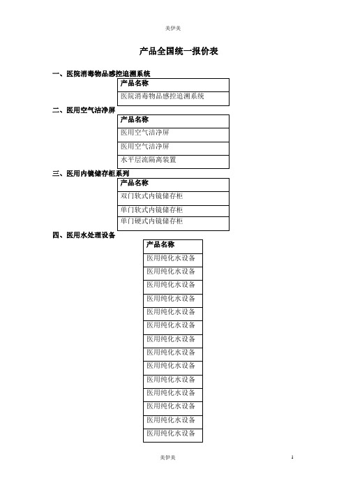
美美公司出产什么产品呢?
医用拖鞋(淡紫色)
医用拖鞋(淡紫色)
医用拖鞋(金黄色)
医用拖鞋(金黄色)
医用拖鞋(金黄色)
医用拖鞋(金黄色)
医用拖鞋(浅蓝色)
医用拖鞋(浅蓝色)
医用拖鞋(浅蓝色)
医用拖鞋(浅蓝色)
医用拖鞋(红色)
医用拖鞋(红色)
医用拖鞋(红色)
医用拖鞋(红色)
医用拖鞋(薄荷绿色)
医用拖鞋(薄荷绿色)
器械串(U型架)
器械串(U型架)
器械串(U型架)装台
十二、清洗防护用品
产品名称
防护面罩
防护眼罩
防护眼镜
防水罩袍(浅黄色小号)
防水罩袍(浅黄色中号)
防水罩袍(浅黄色大号)
防水罩袍(浅蓝色小号)
防水罩袍(浅蓝色中号)
防水罩袍(浅蓝色大号)
防水罩袍(浅绿色小号)
防水罩袍(浅绿色中号)
5
单槽污物清洗槽柜
6
长槽污物清洗槽
7
单槽自动洗手池
8
清洗工作台(双层)
9
清洗工作台(单层)
10
污物车
11
污物下收车
编号
产品名称
1
器械检查打包台(密度板)
2
器械检查打包台(密度板)
3
器械检查打包台
4
器械检查打包台
5
包布、敷料检查打包台(密度板)
6
包布、敷料检查打包台(密度板)
7
包布、敷料检查打包台
8
包布、敷料检查打包台
医用纯化水设备
医用纯化水设备
医用纯化水设备
医用纯化水设备
医用纯化水设备
医用纯化水设备
医用纯化水设备
卡萨帝 单支臻藏酒柜BJC-1SAU1 说明书
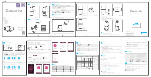
电子酒柜使用说明书青岛海尔特种电冰柜有限公司横放时显示温度上/下调节键温度上/下调节键WIFI配置键温度显示区WIFI显示区℃氛围灯控制键长按“>”2S,进入温度设置状态,此时【温度显示区】的数字闪烁,通过调节【温度上/下调节键】设置,每短按一下“<”,设置温度增加一度,每短按一下“>”,设置减少一度。
温度设置范围为5-18℃,选定温度后,停止操作5s,系统自动默认当前设置参数,并退出温度设置,屏幕显示实际温度,温度上下调节键指示灯恢复半亮显示。
长按“∨”2S,进入温度设置状态,此时【温度显示区】的数字闪烁,通过调节【温度上/下调节键】设置,每短按一下“∧”,设置温度增加一度,每短按一下“∨”,设置减少一度。
温度设置范围为5-18℃,选定温度后,停止操作5s,系统自动默认当前设置参数,并退出温度设置,屏幕显示实际温度,温度上下调节键指示灯恢复半亮显示。
一下减少1℃停止操作5S,不再闪烁℃一下减少1℃停止操作5S,不再闪烁℃装箱单六名称电子酒柜(个)底座(个)电源适配器(套)数量111·6··7·点击首页我的酒柜标签【 】,进入页面,按照提示操作:说明书(份1)名 称 数 量产品型号电子酒柜底座电源适配器 酒具使用说明书BJC-1SAU1 1 1 1 11 BJC-1SA2U1 1 1 1 01 BJC-1SA3 1 1 1 0 1 BJC-1SCRU1 1 1 1 1 1 BJC-1SCWU111111手机扫描二维码下载智能酒柜软件使用说明书使用前请仔细阅读说明书请妥善保存,以备参阅本产品只适合在中国大陆销售和使用本产品因不断研究改进,保留各部件的变更权利,恕不另行通知,敬请谅解。
Deity 智能场记板TC-SL1 使用者指南说明书

Deity 智能场记板TC-SL1 使用者指南前言感谢您购买DEITY产品。
重要提示F C C 符合声明: 请认真阅读本使用者指南。
请妥善保管使用者指南。
将产品交给他人使用时,请务必附带本使用者指南。
请注意所有警告提示并遵守使用者指南内的所有指令。
警告:请勿将本产品放置在有腐蚀性化学物品的地方,以免产品受到腐蚀,被腐蚀可 能引起产品故障。
请用软布、干布清洁本产品。
本产品属于精密仪器,请避免使用时掉落、碰撞或承受重击。
请保持产品远离液体,液体进入产品可能会导致电子短路或破坏结构。
请将本产品保存在干燥、干净、无尘的环境中。
需要维修时请联系授权的维修人员。
本产品内有精密电子线路。
未经许可擅自拆卸导致故障,不在本司保修范围内,但用户可以付费维修。
本产品已经过RoHS、CE、FCC、KC和日本MIC认证,请参考相关国家标准使用和操作。
因使用操作不当而造成机器损坏,不在保修范围内,但用户可以付费维修。
此使用者指南依据本公司严格测试制定。
设计和规格如有变更,恕不另行通知。
此产品符合 FCC 规则第 15 部分中的规范。
操作产品须符合以下两个条件:(1) 此设备不会导致有害干扰;(2) 此设备可承受任何外来干扰,包括可能导致非预期操作的干扰。
【警告】如果用户未经DEITY明确许可而进行改动或改装,可能会影响您的保修服务。
【注】此设备经测试确定符合 B 类数码设备(依照 FCC 规则第 15 部分规范)的限制。
这些限制的设计旨在为居住场所安装条件下的有害干扰提供合理的保护。
此设备生成、使用并可以发射射频能量。
如果未按照指示安装和使用,可能对无线电通信造成有害干扰。
但是,在特定安装条件下,不保证这类干扰不会发生。
如果此设备确实对无线电或电视机接收信号造成有害干扰,而这点可以通过关闭和打开设备来确定,那么建议用户尝试使用以下一种或多种措施来消除干扰: 调整接收天线的方向或重新放置。
扩大设备与接收器之间的距离。
将设备连接到其他电路的插座中,而不是接收器所连接电路的插座。
- 1、下载文档前请自行甄别文档内容的完整性,平台不提供额外的编辑、内容补充、找答案等附加服务。
- 2、"仅部分预览"的文档,不可在线预览部分如存在完整性等问题,可反馈申请退款(可完整预览的文档不适用该条件!)。
- 3、如文档侵犯您的权益,请联系客服反馈,我们会尽快为您处理(人工客服工作时间:9:00-18:30)。
迪新微电脑数显单门软镜储存柜
一、迪新微电脑数显单门软镜储存柜
内胆采用的是进口高分子材料独立开模一体成型,外部材料采用纳米抗菌喷塑技术,能有效抑制各种病菌。
柜内空间紧密效果优异,整体简洁、实用、美观、大方。
内设智能化自动控制紫外线循环风程序。
工作自动累计,照明和干燥等功能,模式简单方便易操作。
软镜柜内设计有透明亚克力制成的内镜悬挂系统,该系统设有上下,全方位的定位内镜,防止相互之间碰撞,适应不同尺寸内镜存放的需要。
严格按照《内镜清洗消毒技术操作规范(2016年版)》的第三章第二十六条中的“镜体应悬挂,弯角固定钮应置于自由位”的规范,保持内镜垂直存放,避免碰撞造成损伤,是现代内镜中心、手术室等科室必备的设备。
二、迪新微电脑数显单门软镜储存柜基本规格
(1)型号是DX-SX-1;
(2)外形的尺寸(mm)630*535*2080;
(3)储存量为3-4条;
(4)消毒的模式可以是自动的也可以是手动的;
(5)采用的是微电脑的中文显示控制系统。
三、迪新微电脑数显高分子单门软镜储存柜的主要功能
(1)显示时间、日期、星期;
(2)消毒的累积时间;
(3)显示温度和湿度;
(4)循环风干燥;
(5)开门柜内照明LED灯。
四、迪新高分子单门软镜储存柜操作步骤
首先应该先检查电路是否正确连接,是否因长期使用后设备有漏电的现象,如果发现有问题的话应该要立即解决,保障设备安全和人身的安全;最后就可以悬挂已经消好毒的内窥镜,关上储存柜的柜门。
接通电源,大约二十分钟就可以关闭电源,此时的储存柜是处于无菌的状态,可以长时间的储存内窥镜了。
五、迪新高分子单门软镜储存柜适用范围
广泛的用于医院内镜室、手术室、支气管镜室、膀胱镜室、耳鼻喉科、五官科等科室,用于无菌存放各式软式内窥镜、硬式内窥镜及其它手术器械。
泰州市高港区迪新医用设备有限公司是专业的医疗生产厂家,我们公司一直秉承着“精心制造、质量第一、诚信服务、低价销售、重守合同、送货快捷”的宗旨为每一位顾客服务。
