戴尔dell 拆机示意图
戴尔dell N3010 拆机示意图

戴尔DELL N3010拆机图解Dell N3010这个型号在我看来还是可以的,因为它主板是一整块,什么接口都集成在上面,一个东西坏了就可以换整个主板,还有它的散热也不错,但是就是硬盘的位置很蛋疼,在主板下面,要换硬盘非常的麻烦。
进入正题准备工具:十字螺丝刀,最好去淘宝买那中套装的,镊子,用来撬键盘拆之前都是下电池先,两个卡扣一推,就可以拿掉了,内存盖,拿内存。
很简单拿掉内存之后呢,接下来就是拆键盘了。
这个型号的键盘有点点麻烦,俗话说“工欲善其事,必先利其器”。
都有工具了怕什么先去掉背后两颗螺丝(其实我们可以把背后的螺丝一次性都去掉)再用镊子之类的东西从一边撬起。
注意下面的数据线键盘顺利拿掉,接下来就是拆C壳了(C壳就是掌托这块)先去背后螺丝(如果之前去掉螺丝了,这个步骤就可以省了)。
11颗拔掉无线网卡的天线拔掉之后翻过来。
把天线拔出再去螺丝拔掉触摸板电源跟主板的连接线,轻轻的再从右下角轻轻用塑料撬棒撬起这个型号拆主板的话,得先把屏拿掉。
背面的螺丝应该都没了。
拔掉屏线和旁边接地的螺丝还有左右两边的螺丝接下来把屏往上提就可以了(注意用手扶住屏,以防倒了)再把黄色框的塑料条也拿掉去后面两颗螺丝四个卡扣接下来就先把左上角的VGA小板拿掉,为了方便拆风扇。
去掉了上面的螺丝就很好拿了风扇的话就一颗螺丝下面就是主板了。
先去主板上面的螺丝再拔掉右下角的喇叭线和蓝牙在从左边撬起。
稍微用点力底壳就空了。
下来就硬盘吧,,硬盘藏的够深的吧。
哈哈哈只需要去掉一颗螺丝往外一拉就OK了。
你们看了这个也可以自己换硬盘了一般大家拆机无非就这几个原因:加内存,换硬盘,清理灰尘。
拆掉散热器,自己也可以加硅胶了。
到这里也差不多了。
拆屏的话也很简单的。
我就不放了。
如有需要email:ye8@。
如果要其他型号的拆机也可以email我附件:BIOS图0221PSA1000-0222Interval Timer Channel0(mode3)is generating the wrong interrupt count persecond.PSA1000-0223Interval Timer initial clock output level in mode XX is incorrect. PSA1000-0224Interval Timer had wrong time period in mode XX.PSA1000-0231PSA+2000-0231Failure in Interval Timer in mode XX.PSA1000-0232PSA+2000-0232The RTC did not generate periodic ticks.PSA1000-0233PSA+2000-0233The RTC’Seconds‘register is not updating.PSA1000-0234PSA+2000-0234Timeout waiting for RTC update flag to set.PSA1000-0235PM timer1had wrong time period.Expected(d),Actual(d). PSA1000-0241PSA+2000-0241Error enabling A20gate.PSA1000-0242PSA+2000-0242No interrupt detected for IRQ XX–(Name of Interrupt).PSA1000-0312Keyboard test timed out waiting for keyboard response.PSA+2000-0313Error detecting internal touch pad or pointing stick.PSA1000-0321PSA+2000-0321Unable to detect LCD.PSA1000-0322PSA+2000-0322Error accessing the LCD inverter.PSA1000-0326PSA+2000-0326LCD inverter error,unable to turn lamp ON/OFF.PSA+1000-0331No video adapter found.PSA1000-0332Video memory failed.PSA1000-0333PSA+2000-0333Graphics test timed out waiting for keyboard response.PSA1000-0334PSA+2000-0334User reported that graphics patterns were not displayed correctly.PSA+1000-0411Hardware Detect Error–(s)not detected.PSA+1000-0412Hardware Detect Error–Auxiliary LCD cable not detected.PSA+1000-0413Detect Error–LCD cable not detected.PSA+1000-0414Hardware Detect Error–Inverter cable not detected.。
戴尔dell InspironOne 2205 一体机拆机示意图

6 Infrared (IR) blaster connector - Connects to an external IR device.
7 Rear黑色螺丝 去掉,再把后盖往上推就可以拿掉后盖了 往上推
这样就可以看到内存位置,硬盘 和光驱了 接下在是拆底座两边的支架塑料,去掉 3 颗螺丝,
The power button LED is a bi-color light that indicates the Dell Inspiron™ One 2205 power state.
Power Light Status
Power State
Power is off or the system is in an S4 (hibernate) or S5 power state. LED is blank.
The system board cannot start initialization or in an S3 power state. There is a power problem, a device may be malfunctioning or incorrectly installed. 这个其实是 GIF 图片,是上图黄色闪烁的
3
Network connector - Connects your computer to a network or a broadband device if you are using a wired network. The two lights next to the connector indicate status and activity for a wired network connection.
The computer is in power-on state.
dell15-3558拆机图解

dell15-3558拆机图解
废话不多说直接拆,当然先把电池拿掉。
红色区域螺丝全部拆了,把光驱抽出来,然后光驱那边有3个小螺丝也要拆掉,如下图位置
后面螺丝全拆了,光驱也拆了,然后就是键盘了,根据图上提示拆拆拆
翻开键盘看下图,拔掉排线,卸掉螺丝
拿掉键盘就这样子了,接下来从背面把底部的盖子沿边上一圈撬开,注意温柔点,当心有螺丝没拆,硬搞会坏的!!!!!
三下五除二,盖子打开了。
看看里面布局吧,往下就不多说了,大家应该都会了吧
改光驱位硬盘后电池装不上,把电池上一个卡位的脚锯了吧!!或者另想办法
内存12G 开机13秒就这样吧。
戴尔dell+N5010+拆机示意图
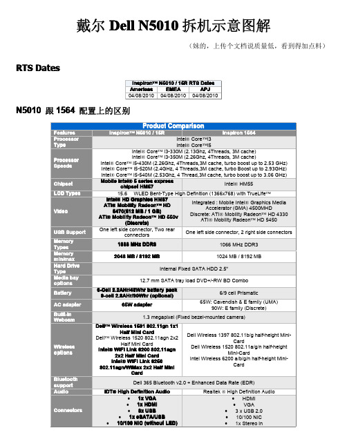
戴尔Dell N5010拆机示意图解
(妹的,上传个文档说质量低,看到得加点料)RTS Dates
N5010跟1564配置上的区别
N5010相对来说还是很简单的,下面就开始吧先拆电池,两边卡扣一拉,就可以拿掉了
再内存盖螺丝去掉,
拿掉盖子之后就可以拿掉内存了
接下来拆键盘,先去掉图示两颗螺丝
去掉螺丝之后,用镊子,顶图示4个位置卡扣,往里面顶进去
拆掉排线
拆掉键盘之后就拿光驱吧。
光驱简单,,去掉螺丝,往外一拉就OK了
接下来拆C壳部分,先去掉背后的螺丝,图示0
反过来,拿掉排线
再去掉5颗螺丝
用塑料的东西撬一下
拆了C壳之后,下面就看到主板了,顺便把屏也拿掉吧。
这样方便拆主板,拔掉图示的线
去掉4颗螺丝
往上一提
接下来就一目了然了。
想拆什么就拆什么,一般大家拆机无非就是加内存和清理灰尘、换硬盘。
是吧拔掉上图的喇叭连接线,之后去掉两颗螺丝
这样主板就拿掉了。
把主板反过来,想拆哪个,比如散热器,
喇叭的话,拿掉主板之后就可以很好拆了,黄圈位置两个卡扣推一下,
下面就说说屏怎么拆吧,先拆B壳,一般用收掰就可以了,轻点
拿掉B壳之后,就可以拆屏了,图示螺丝去掉
拿起来
拔掉屏线,就ok了。
DELL_InspironOne_2020_拆机示意图

戴尔DELL_InspironOne_2020 拆机示意图外观。
正面1 Camera activity indicator— Indicates if the camera is on or off. A solid white light indicates camera activity. 摄像头补光灯2 Camera— Used for video conferencing and capturing video or still images. 摄像头3 Microphone— Provides high quality sound for video chatting and voice recording. 麦克风4 IR Reciever— Recieves singals from the remote control. (Remote control ships only with systems ordered with TV Tuner Card) 红外接口1 Air Vents —Dissipates heat generated by internal components. 散热口,出风口2 USB 2.0 connectors (3)— Connect to USB devices, such as a mouse, keyboard, printer, external drive, or MP3 player. USB接口3 TV-in connector (optional)— Connects to an external antenna to view programs using the optional TV tuner card. TV信号输入接口4 Network connector— Connects your computer to a network or a broadband device if you are using a wired network. RJ45网络接口5 AC adapter connector— Connects to the AC adapter to power the computer. 适配器接口6 Security cable slot— Attaches a commercially available security cable to the computer. 安全锁1 Volume button / Volume/Brightness increase button- Press this button first to get the volume up/down menu and the same button is used to increase volume and brightness. 音量亮度调节2 Brightness button / Volume/Brightness decrease button- Press this button first to get the brightness up/down menu and the same button is used to decrease volume and brightness.音量亮度调节3 Volume/Brightness exit button - Press this button to exit the volume or brightness menu.音量亮度调节4 Audio-out/Headphone connector - Connects to a pair of headphones. 耳机接口5 Audio-in/Microphone connector- Connects to a microphone or input signal for use with audio playback devices like CD/MP3 player. 麦克风接口6 USB 2.0 connector - Connects to USB devices, such as a mouse, keyboard, printer, external drive, or MP3 player. USB2.接口7 USB 2.0 connector- Connects to USB devices, such as a mouse, keyboard, printer, external drive, or MP3 player. USB2.接口8 8-in-1 Media Card Reader - Provides a fast and convenient way to view and share digital photos, music, videos, and documents stored on memory cards. 读卡器接口.1 Optical drive - Plays or records CDs, DVDs, and Blu-ray Discs (optional). 光驱2 Hard-drive activity light - Turns on when the computer reads or writes data. A blinking white light indicates hard drive activity. 硬盘指示灯3 Power button - Turns the computer on or off when pressed. The light on the button indicates the following power states:•Solid amber: The computer has detected an error during Power-on self-test (POST).•Breathing amber: The computer is in sleep/standby state or There is a possibility of system facing an issue.•Solid white: The computer is ON.•Off: The computer is off or in hibernate state 电源按键开关接下来就是拆机过程了。
DellInspiron笔记本电脑拆解清尘图解教程

本人电脑用了两年没有拆过,现在也来个拆解教程拆解就要胆大心细直接上图:得心应手的工具是必不可少的。
开始前首先要把身上的静电放一下,最没用的电池要首先拆下来。
红色圈圈的地方是光驱的固定螺丝,一会咱就把它拆下来。
电池拿下来后下面有两颗螺丝可以先拧下来,它连着下面这张图的面板。
电池后面的螺丝拆掉后就可以把C板就是上图的板子轻轻的撬开,要慢慢的不可用力过大。
拆硬盘---把第一图的两颗小螺丝拧下来后就用拉出硬盘。
拆光驱---拧下这颗螺丝后,光驱就可以拉出来了。
其实我们最主要的目地就是拿出这东西就可以清除90%的尘絮,第二张图的红线位置会隔出越来越多烦人的灰尘,内部的风扇还真没什么可以清理的。
如果还要继续拆的话就要把内存取出来。
那两根连接线一白一黑是无线网卡的,先把白黑线拔出来,再把网卡向外抽出。
好了后面的螺丝可以全部都拧下来了,看清楚哦,一颗也不能落下哦!接下来我们把电脑翻过来两颗螺丝固定着键盘,拧下螺丝后提出键盘,键盘下面还有排线所以不要太用力。
我认为用手指甲比较安全,把黑色的扣件翻起来后把排线出来,边上那个小点的排线是触摸位置排线,原理一样也一起搞下来。
这是随后我们看到的画面,这里只有屏幕的排线可以重点说说,其它的自行理解拆红圈里的排线时手要把着标签向上提,需要一点点力量才能完成,小的我只能为您祈祷啦!呵呵绿色的圈可别忘记拧下来哦!看到绿色的圈了没有,那个线很万恶的要小心哦!我本人就没有动它只是拉出来一点点把面板可以立起来不碍事就OK。
拆主板时就这两个位置需要注意一下,左图要先把它拆下来,然后向上拔出来。
把固定主板的几颗螺丝都拧下来后右图的插槽也连着主板要拔出来。
看到风扇了!拆下来清理一下吧!注意的是风扇的电线也连着主板拧掉主板螺丝后别忘了把风扇的电线也拔下来。
dell15-3558拆机现用图解
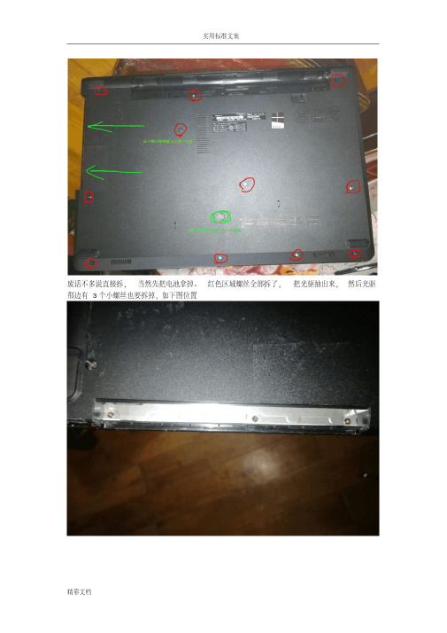
废话不多说直接拆,当然先把电池拿掉。
红色区域螺丝全部拆了,把光驱抽出来,然后光驱那边有3个小螺丝也要拆掉,如下图位置
后面螺丝全拆了,光驱也拆了,然后就是键盘了,根据图上提示拆拆拆翻开键盘看下图,拔掉排线,卸掉螺丝
拿掉键盘就这样子了,接下来从背面把底部的盖子沿边上一圈撬开,注意温柔点,当心有螺丝没拆,硬搞会坏的!!!!!
三下五除二,盖子打开了。
看看里面布局吧,往下就不多说了,大家应该都会了吧
改光驱位硬盘后电池装不上,把电池上一个卡位的脚锯了吧!!或者另想办法
内存12G 开机13秒就这样吧。
戴尔笔记本拆装图解

戴尔笔记本拆装图解〔Dell Inspiron 1440 〕一、卸下电池:1. 请关闭电脑并拔出所有连接线缆2. 将电脑翻转过来。
3. 将电池释放闩锁滑动到打开位置。
4. 将电池滑出,然后将其从电池槽中提出。
二、卸下硬盘驱动器:1、取出电池。
警告:当硬盘驱动器未安装在电脑中时,请将其存放在保护性防静电包装中〔请参阅电脑附带的安全说明中的防止静电损害〕。
2、拧下将硬盘驱动器部件固定到电脑基座的两颗螺钉。
3、将硬盘驱动器部件从硬盘驱动器凹槽中滑出。
1 螺钉 (2)2 硬盘驱动器部件4、拧下将硬盘驱动器挡板固定至硬盘驱动器的两颗螺钉。
5、卸下硬盘驱动器。
1 硬盘驱动器挡板2 螺钉 (2)三、卸下光盘驱动器:1、取出电池。
2、拧下将光盘驱动器固定到电脑基座的螺钉。
3、用塑料划片推动槽口,以便从光盘驱动器托架中卸下光盘驱动器。
4、将光盘驱动器滑出光盘驱动器托架。
1 光盘驱动器2 螺钉3 槽口4 塑料划片四、卸下模块护盖:1、取出电池。
2、拧下将模块护盖固定到电脑基座的螺钉。
3、将护盖以一定的角度提离电脑〔如图中所示〕。
1 模块护盖卡舌 (4)2 模块护盖3 螺钉五、卸下内存模块:1、取出电池〔请参阅取出电池〕。
2、卸下模块护盖〔请参阅卸下模块护盖〕。
警告:为防止对内存模块连接器造成损坏,请勿使用工具将内存模块固定夹张开。
3、用指尖小心地将内存模块连接器两端的固定夹张开,直至模块弹起。
4、从内存模块连接器卸下内存模块。
1 内存模块连接器2 固定夹 (2)3 内存模块六、卸下无线小型插卡:1、取出电池。
2、卸下模块护盖。
3、从小型插卡上拔下天线电缆。
1 小型插卡2 螺钉3 天线电缆连接器 (2)5、拧下将小型插卡固定到系统板连接器的螺钉。
6、将小型插卡从系统板连接器中提出。
七、卸下中心控制护盖:1、取出电池。
2、翻转电脑使其正面朝上,然后将显示屏打开到最大程度。
警告:卸下中心控制护盖时请格外小心。
此护盖极易损坏。
戴尔dell N 拆机示意图
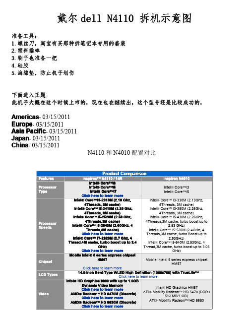
Click here to learn more
USB Support
Two Left connector: • 1 USB 2.0 Connector • 1 USB/eSATA Connector
1 Rear Connector • USB 3.0 Connector 1 Right Connector • USB 3.0 Connector
Beep s
1
2
附录。。主板报警提示信息
Beep Code Overview
Description
Possible Cause
BIOS ROM checksum in progress or failure No Memory (RAM) detected
4Threads,3M cache)
4Threads,3M cache, turbo boost up to
Intel® Core™ i5-2540M (2.60GHz, 4 Threads,3M cache)
2.53 GHz) Intel® Core™ i5-520M (2.4GHz, 4
Click here to learn more
configurable to less than 2.27 kg (5.01lb)
Windows® 7 Home Basic 64-Bit all language versions
Windows® 7 Home Premium 64-Bit all language versions
Windows® 7 Professional 64-Bit all language versions
戴尔dell N4050 拆机示意图

戴尔DELL N4050拆机图解
个人认为戴尔N4050M4040这连个型号设计的很失败,具体大家百度就可以了,特别是M4040。
下面还是进入正题
N4050M4040拆机的方法是一样的,因为他们只是配置不同,外观设计,整体布局都是一样的。
先了解一下外观
依次是:电源指示灯、硬盘灯、充电指示灯、无线网卡指示灯
好像颜色就只有红、黑
工具:
1:塑料撬棒 2.十字螺丝刀 3.一字螺丝刀4.小十字螺丝刀
这个机子设计有点不一样,内存在键盘下面,拆掉键盘才能加内存先从背面着手,,拆电池
拿掉电池之后,不用着急去背面的螺丝,可以先拆键盘。
用一字螺丝刀或者塑料撬棒顶4个圆圈位置卡扣,往里顶
拿掉键盘就可以看到内存了
接下来是光驱,蓝色圈那里其实有两枚螺丝,一枚是黑色,一枚是白色,装回去的时候一定要注意位置,白色比黑色的要短
拿掉光驱之后就拆C壳了,8颗螺丝去掉
去电源排线和触摸板排线
3颗螺丝
接下来就一目了然了。
想拆哪个都很简单。
END。
DELL Vostro A840拆解图

今天来了个A840
挺惨的
还是先拿下电池,然后拿掉后面的基本件盖板,这机器首先就要拆掉无线网卡天线
这个位置一颗螺丝拿下光驱
接着依然是拆掉所有见到的螺丝吧,记住长短
这下面有螺丝哦,一共四个,是固定硬盘的,话说我很鄙视这种设置
反过来打开屏,下了按键盖板组件,这个不是很好弄,悠着点儿别掰断了就难看死了
键盘上面两颗螺丝,拆掉
那键盘的时候注意后面的线
把无线网天线从这个窟窿里拽出来吧然后别忘了从机壳卡槽里弄出来放在一边
拔掉显卡和开机按键的排线
然后来搞定屏幕,在本本的PP上有两个这东东,下面是屏轴螺丝
拆掉以后就可以慢慢的向上拿起屏幕了,切记切记这个时候不要转动屏幕了,不然后果自负
C壳的最后两颗螺丝藏在了这里,当然是一面一个,我只拍了一面的
终于分家了
是不是很脏啊…………
拆掉上下两颗固定风扇的螺丝
这个状态显然已经不可能再达到散热的作用了
清理干净以后是不是清爽了许多?
拆这个风扇需要把上面4个“焊”点弄掉了,再装回去的话就只能粘了,我选择用电工胶布粘上的日后再拆还不费力
搞定以后就还原吧
最后补充两句,刚刚背面的四颗固定硬盘的螺丝如果不拆主板或者硬盘的情况下不必拧下的那个不耽误拆风扇青灰。
dell 拆机图解
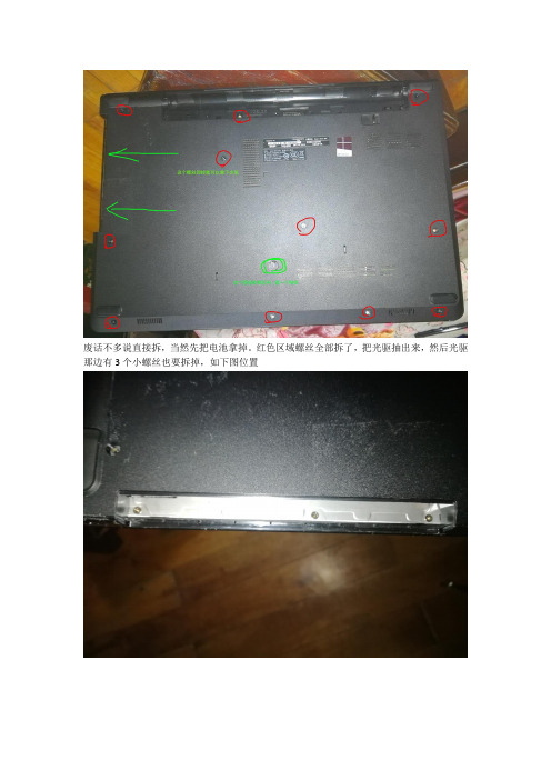
废话不多说直接拆,当然先把电池拿掉。
红色区域螺丝全部拆了,把光驱抽出来,然后光驱那边有3个小螺丝也要拆掉,如下图位置
后面螺丝全拆了,光驱也拆了,然后就是键盘了,根据图上提示拆拆拆翻开键盘看下图,拔掉排线,卸掉螺丝
拿掉键盘就这样子了,接下来从背面把底部的盖子沿边上一圈撬开,注意温柔点,当心有螺丝没拆,硬搞会坏的!!!!!
三下五除二,盖子打开了。
看看里面布局吧,往下就不多说了,大家应该都会了吧
改光驱位硬盘后电池装不上,把电池上一个卡位的脚锯了吧!!或者另想办法
内存12G 开机13秒就这样吧。
戴尔dell_1464_拆机示意图
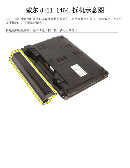
戴尔dell1464拆机示意图dell1464我认为这款笔记本设计还是很经典的,相比起其他的型号,这款散热,外观还是不错的。
下面就开始吧拆电池的话很简单,左右两边卡扣一拉,就可以拿掉了。
拿掉电池之后,接下来就拆内存盖了,黄框两颗螺丝去掉,拿掉就可以看到内存、无线网卡、纽扣电池内存的话很好拿,顺便也把无线网卡也拿掉吧,拔掉天线,去掉螺丝就可以拿掉无线网卡了。
接下来拆键盘周围的那个框,拆这个的时候要注意,这个塑料框比较脆弱,我也拆断了几个,注意卡扣位置的时候轻一点。
先去两颗螺丝再反过来,用手从右边或者左边位置往上掰起,注意黄圈处的电源开关连接线,拿掉了框,就拆键盘了。
去掉两颗螺丝,去掉螺丝之后,还有大概4个塑料卡扣扣住的,注意一下,翻过来注意数据线上面说着说着忘记拆光驱了,光驱很简单,看图,去螺丝,往外一拉接下来要拆这个,C壳去掉图示的螺丝,,把天线拉出来拔掉触摸板的连接线去掉四颗螺丝从光驱位置往上掰起,为了方便拆主板,顺便把屏拿掉,拔掉屏线屏线上面接地的螺丝左右两边的螺丝之后往上提起来,,接下来拆硬盘,先拆右边的USB音频小板黄圈处两边接口处黑色压条掰起,一定要轻轻的再去螺丝就可以拿掉了再把这两颗螺丝去掉,往外一拉,硬盘就下来了一般我们拆机的目的应该就是换硬盘,清理灰尘,加内存之类的。
拔掉风扇的连接线,两颗螺丝,这样就可以拿掉了,赶紧看看灰尘多不多接下来拆主板。
屏我们之前已经拿掉,那只要拔电源线就可以了,还有喇叭线麦克风的线去掉主板上的螺丝稍微往上抬起,就可以拿掉了。
下面主板上的散热器之类的就很好拆了,就不一一说明了有问题Email:ye8@。
戴尔dell拆机示意图

戴尔dell 5420-7420 拆机示意图因为dell 5420 和 7420的构造设计是一样的,只是配置不同。
最直接的差别就是显卡,一个是GT 630 一个是GT 640Intel® Core i3Intel® Core i5Intel® Core i7(Sandy Bridge and Ivy Bridge Processors) Click here to learn moreIntel® Core i3Intel® Core i5Intel® Core i7(Sandy Bridge and Ivy Bridge Processors) Click here to learn moreIntel® HM77 Chipset Click here to learn moreIntel® HM77 Chipset Click here to learn more1333MHz DDR3 - Sandy Bridge Processors 1600MHz DDR3 - Ivy Bridge Processors Click here to learn more 1333MHz DDR3 - Sandy Bridge Processors 1600MHz DDR3 - Ivy Bridge Processors Click here to learn more14.0" HD WLED TrueLife (1366 X 768)14.0" HD+ WLED TrueLife (optional) (1600 X 900)Click here to learn more14.0" HD WLED TrueLife (1366 X 768) 14.0" HD+ WLED TrueLife (optional) (1600 X900)Click here to learn moreIntegratedIntel HD Graphics 3000 (Sandy Bridge Processors) Intel HD Graphics 4000 (IvyBridge Processors)DiscretenVidia GeForce GT 640M Click here to learn moreIntegratedIntel HD Graphics 3000 (Sandy Bridge Processors) Intel HD Graphics 4000 (IvyBridge Processors)DiscretenVidia GeForce GT 630M Click here to learn moreConexant CX20672-217 Audio controller Click here to learn more Conexant CX20672-217 Audio controller Click here to learn moreSATA HDD 2.5"mSATA SSD Click here to learn moreSATA HDD 2.5"mSATA SSD Click here to learn more1703 WiFi + Bluetooth 4.0 Half Mini Card1704 WiFi + Bluetooth 4.0 Half Mini Card WLAN 1901 WiFi + Bluetooth 4.0 Half Mini Card Intel® 2230 WiFi + Bluetooth 4.0 Half Mini Card Click here to learn more720p HD (1280x720) + Digital MicrophoneClick here to learn more10/100/1000 NIC (without LED) Click here to learn more 10/100/1000 NIC (without LED) Click here to learn more8-in-1 Media Card Reader Click here to learn more65W / 90WClick here to learn more6-Cell 2.2AHr/48Whr battery pack Click here to learn more 6-Cell 2.2AHr/48Whr battery pack Click here to learn moreFeatures on the front side of the chassis of the Inspiron™ 7420/14R laptop are as follows:Front LCD Area 前面屏幕区域Features on the front side (LCD Area) of the chassis of the Inspiron™ 7420/14R laptop are as follows:Front Keyboard and Palmrest AreaFeatures on the front side (Keyboard and Palmrest area) of the chassis of the Inspiron™ 7420/14R laptop are as follows:Features on the left side of the chassis of the Inspiron™ 7420/14R laptop are as follows:Chassis RightFeatures on the right side of the chassis of the Inspiron™ 7420/14R laptop are as follows:下面开始拆机。
戴尔DELL_InspironOne_2020 拆机示意图
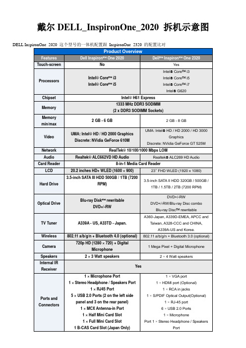
戴尔DELL_InspironOne_2020 拆机示意图外观。
正面1 Camera activity indicator— Indicates if the camera is on or off. A solid white light indicates camera activity. 摄像头补光灯2 Camera— Used for video conferencing and capturing video or still images. 摄像头3 Microphone— Provides high quality sound for video chatting and voice recording. 麦克风4 IR Reciever— Recieves singals from the remote control. (Remote control ships only with systems ordered with TV Tuner Card) 红外接口1 Air Vents —Dissipates heat generated by internal components. 散热口,出风口2 USB 2.0 connectors (3)— Connect to USB devices, such as a mouse, keyboard, printer, external drive, or MP3 player. USB接口3 TV-in connector (optional)— Connects to an external antenna to view programs using the optional TV tuner card. TV信号输入接口4 Network connector— Connects your computer to a network or a broadband device if you are using a wired network. RJ45网络接口5 AC adapter connector— Connects to the AC adapter to power the computer. 适配器接口6 Security cable slot— Attaches a commercially available security cable to the computer. 安全锁1 Volume button / Volume/Brightness increase button- Press this button first to get the volume up/down menu and the same button is used to increase volume and brightness. 音量亮度调节2 Brightness button / Volume/Brightness decrease button- Press this button first to get the brightness up/down menu and the same button is used to decrease volume and brightness.音量亮度调节3 Volume/Brightness exit button - Press this button to exit the volume or brightness menu.音量亮度调节4 Audio-out/Headphone connector - Connects to a pair of headphones. 耳机接口5 Audio-in/Microphone connector- Connects to a microphone or input signal for use with audio playback devices like CD/MP3 player. 麦克风接口6 USB 2.0 connector - Connects to USB devices, such as a mouse, keyboard, printer, external drive, or MP3 player. USB2.接口7 USB 2.0 connector- Connects to USB devices, such as a mouse, keyboard, printer, external drive, or MP3 player. USB2.接口8 8-in-1 Media Card Reader - Provides a fast and convenient way to view and share digital photos, music, videos, and documents stored on memory cards. 读卡器接口.1 Optical drive - Plays or records CDs, DVDs, and Blu-ray Discs (optional). 光驱2 Hard-drive activity light - Turns on when the computer reads or writes data. A blinking white light indicates hard drive activity. 硬盘指示灯3 Power button - Turns the computer on or off when pressed. The light on the button indicates the following power states:•Solid amber: The computer has detected an error during Power-on self-test (POST).•Breathing amber: The computer is in sleep/standby state or There is a possibility of system facing an issue.•Solid white: The computer is ON.•Off: The computer is off or in hibernate state 电源按键开关接下来就是拆机过程了。
dell_N4030_拆机图

30拆机示意图N4030戴尔dell N40QQ:297322138先看一下机子的基本信息跟N4020的比对看完之后接下就开始拆了.第一步基本上都是先拆电池,这样就拿掉电池了之后再拿光驱,拧掉图示红圈处的螺丝就可以向外拿掉光驱了接下来的拆硬盘也很简单(N4030还是很好拆的),拧掉黄圈的两颗螺丝,在往外一拉就哦了,机子过保修之后自己都可以更换硬盘了。
再拆内存,先把内存盖子上面的螺丝去掉,拿掉盖子之后就可以看到内存了再拆键盘,图示两颗螺丝去掉在用镊子之类的顶掉三个图示卡扣。
在往上一拉,拔掉跟主板连接的排线,就可以拿掉了拆掉键盘之后就可以到无线网卡小板了,顺便也拆了。
这个很简单。
O(∩_∩)o接下来要拆C壳了。
先拆背面的螺丝。
黄圈的螺丝都要去掉,翻过来再去掉这5颗。
把跟主板连接的开关排线和触摸板排线拿掉拿掉之后,先从右边慢慢撬起。
拆掉C壳之后就可以看到主板了在拆主板之前先把屏给卸下来。
1.拔掉屏线 2.去掉两颗螺丝。
之后就可以卸掉屏了就剩赤裸裸的主板了,一般我们要清洁风扇的话就得把主板卸了。
去掉3颗螺丝和喇叭线接下来就把风扇拆下来清理一下吧,先拔掉风扇电源线,之后去掉螺丝这样就简简单单的把散热器拆下来了,要清理风扇里面的灰尘的话,只要去掉风扇上面的4颗螺丝就可以了剩下的就剩这样了,左上角的网卡+usb+I/O小板。
去掉上面的螺丝就可以拿下来主板的CPU得这样拆,用一字螺丝刀旋转180度拆主板的工作基本上也就这样。
接下来就是拆屏,这个得小心点,先拆外面一层壳这样之后就可以拆屏。
小心小心再小心。
先去螺丝去掉之后就可以拿了。
可能会有双面胶粘住。
稍微用点力拆掉的屏上面有屏线,也得拆拆拆,这里也得轻轻的拆机完成!!!!!!!!!!!!!!!!拆机完成附一些有用的资料开机报警声。
- 1、下载文档前请自行甄别文档内容的完整性,平台不提供额外的编辑、内容补充、找答案等附加服务。
- 2、"仅部分预览"的文档,不可在线预览部分如存在完整性等问题,可反馈申请退款(可完整预览的文档不适用该条件!)。
- 3、如文档侵犯您的权益,请联系客服反馈,我们会尽快为您处理(人工客服工作时间:9:00-18:30)。
戴尔dell 5420-7420 拆机示意图
因为dell 5420 和 7420的构造设计是一样的,只是配置不同。
最直接的差别就是显卡,一个是GT 630 一
个是GT 640
Intel® Core i3
Intel® Core i5
Intel® Core i7
(Sandy Bridge and Ivy Bridge Processors) Click here to learn more
Intel® Core i3
Intel® Core i5
Intel® Core i7
(Sandy Bridge and Ivy Bridge Processors) Click here to learn more
Intel® HM77 Chipset Click here to learn more
Intel® HM77 Chipset Click here to learn more
1333MHz DDR3 - Sandy Bridge Processors 1600MHz DDR3 - Ivy Bridge Processors Click here to learn more 1333MHz DDR3 - Sandy Bridge Processors 1600MHz DDR3 - Ivy Bridge Processors Click here to learn more
14.0" HD WLED TrueLife (1366 X 768)
14.0" HD+ WLED TrueLife (optional) (1600 X 900)
Click here to learn more
14.0" HD WLED TrueLife (1366 X 768) 14.0" HD+ WLED TrueLife (optional) (1600 X
900)
Click here to learn more
Integrated
Intel HD Graphics 3000 (Sandy Bridge Processors) Intel HD Graphics 4000 (IvyBridge Processors)
Discrete
nVidia GeForce GT 640M Click here to learn more
Integrated
Intel HD Graphics 3000 (Sandy Bridge Processors) Intel HD Graphics 4000 (IvyBridge Processors)
Discrete
nVidia GeForce GT 630M Click here to learn more
Conexant CX20672-217 Audio controller Click here to learn more Conexant CX20672-217 Audio controller Click here to learn more
SATA HDD 2.5"
mSATA SSD Click here to learn more
SATA HDD 2.5"
mSATA SSD Click here to learn more
1703 WiFi + Bluetooth 4.0 Half Mini Card
1704 WiFi + Bluetooth 4.0 Half Mini Card WLAN 1901 WiFi + Bluetooth 4.0 Half Mini Card Intel® 2230 WiFi + Bluetooth 4.0 Half Mini Card Click here to learn more
720p HD (1280x720) + Digital Microphone
Click here to learn more
10/100/1000 NIC (without LED) Click here to learn more 10/100/1000 NIC (without LED) Click here to learn more
8-in-1 Media Card Reader Click here to learn more
65W / 90W
Click here to learn more
6-Cell 2.2AHr/48Whr battery pack Click here to learn more 6-Cell 2.2AHr/48Whr battery pack Click here to learn more
Features on the front side of the chassis of the Inspiron™ 7420/14R laptop are as follows:
Front LCD Area 前面屏幕区域
Features on the front side (LCD Area) of the chassis of the Inspiron™ 7420/14R laptop are as follows:
Front Keyboard and Palmrest Area
Features on the front side (Keyboard and Palmrest area) of the chassis of the Inspiron™ 7420/14R laptop are as follows:
Features on the left side of the chassis of the Inspiron™ 7420/14R laptop are as follows:
Chassis Right
Features on the right side of the chassis of the Inspiron™ 7420/14R laptop are as follows:
下面开始拆机。
左右两边卡扣推开
下面拆硬盘和内存的盖子。
去掉螺丝就可以了。
下面拆内存和硬盘
拔掉数据线,之后去掉固定的四颗螺丝
拆光驱。
去掉固定的螺丝。
一拉就出来了
拆键盘,有些配置如果有背光的,那拆的时候要注意背光的数据线
下面拆C壳。
第一次拆可能有点紧,最好慢慢来,因为太重了可能会导致卡扣断了。
去掉背面图示的螺丝,
建议去掉背面的所有的螺丝,以免有遗漏
拔掉触摸板数据线
右上角的功能键的数据线
左上角的开关数据线
拔掉屏线
去掉图示的螺丝。
不要有遗漏
C壳的卡扣有图示这么多,从左上角或者右上角开始翘起,,
拆电源线。
拔掉线,去掉螺丝,就可以拿掉了
下面随便那屏幕拿下来,这样好拆主板. 去掉固定的螺丝,拔掉天线
拆风扇,太简单了,。
,拔掉接头,就可以拿掉了
拆无线网卡,也很简单,去固定螺丝
拆喇叭,拔掉接口,注意喇叭的连接线。
比较细
拆主板。
去掉螺丝就可以拿起来了
拆小板。
去掉固定螺丝。
后面拆散热器和CPU就很简单了。
就不一一说明了
Ok。
完了
附录:报警声的含义。
