03_ServiceBusConsole
黑莓手机错误代码详解blackberry系统错误提示

黑莓手机错误代码详解blackberry系统错误提示黑莓手机错误代码详解 blackberry系统错误提示希望国内的黑莓用户对黑莓手机出错提示有个很好的认识,从而来解决问题。
101 Previous startup failed当jvm启动过程中,前一个启动的项目失败了,设备已经被重置。
这个错误表明jvm在启动时找到“启动进行中”这个标志位已经设置了,当前屏幕信息为:有意停止“系统继续重置”这个死循环,来纠正系统当前不正确的启动操作102 Invalid code in filesystem在文件系统中发现无效的代码。
手持设备的系统检查.cod文件的变动时,在一些.cod文件中检测到这个问题。
他肯可能是表明生成过程中发生了错误,即在cod文件中存在一个有问题的签名。
如果一些用户操作设备导致这个问题的发生,文件系统的代码被破坏,复位的周期将是连续循环的。
唯一的恢复方法是擦去设备并且恢复一个新的系统。
103 Cannot find starting address找不到启动的地址,用于启动系统的引导cod文件找不到。
这个错误表明一个用于引导系统的cod文件没有安装到设备上,或者格式不正确。
104 Uncaught:非预期:《java模块名》jvm诊断出一个非预期的java代码异常错误抛出,程序可以继续执行,或者手持设备可以用桌面管理器连是USB线安装一个程序调试器来查看这些错误信息。
事件日志里应该包含了异常错误的信息105 Example, DbRecSize( %d ) -> %d举例,DbRecSize( %d ) ->%d文件系统API已经为一种特定的操作返回一种错误状态码,他可能表明在jvm 上存在一个无效的或者错误的文件系统106 Graphics system error图形系统错误,在设备的图形系统里一个错误发生并被检测到107 operator new() called在jvm里,操作new()回调一个c++类,该函数代码没有被正确的从VMRamObject对象来继承,新操作符需要被正确的继承。
Oracle+Service+Bus安装、配置、操作详解
Oracle Service Bus安装、配置、操作详解安装Oracle Service Bus1:下载Oracle Service Bus你可以在/alservicebus/上下载,或者直接访问。
建议尽量下载最新版本的。
本说明书基于Oracle Service Bus 10gR3(安装文件:192.168.1.15/E:/OSB/Oracle Service Bus 10gR3--osb103_wls103_win32.exe)2: 双击该exe文件, 启动安装程序之后出现启动界面,等待一会后,出现欢迎界面,单击"Next"。
3.选择OSB的安装目录,这里保持默认值C:\bea,单击"Next"。
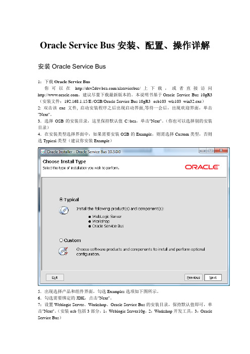
(你也可以选择别的安装目录)4.在安装类型选择界面中,如果需要安装OSB的Example,则需选择Custom类型,否则选Typical类型(建议你安装Example)5.出现选择产品和组件界面,勾选Examples选项如下图所示。
6.勾选需要绑定的JDK,点击"Next"。
7:设置Weblogic Server、Workshop、Oracle Service Bus的安装目录,保持默认值即可,单击"Next"。
(安装osb包括3部分,1:Weblogic Server10g,2:Workshop开发工具,3:Oracle Service Bus)10.接下来都保持默认值,单击"Next"即可。
(安装过程大有微软产品之风,相当easy,基本上一路next就ok)配置Oracle Service Bus(创建OSB的Domain)1:启动“Configuration Wizard”创建新域。
Configuration Wizard 位于<OSB 主目录>/wlserver_10.3/common/bin目录中。
H3C S3100系列以太网交换机 安装手册(V1.07)
如果您在使用过程中发现产品资料的任何问题,可以通过以下方式反馈: E-mail:info@ 感谢您的反馈,让我们做得更好!
前言
本书简介
《H3C S3100 系列以太网交换机 安装手册》主要介绍了 H3C S3100 系列以太网交换机的硬件特 性及交换机的安装、配置和维护。在安装交换机前及安装过程中,为避免可能出现的设备损坏和人 身伤害,请仔细阅读本手册。本手册包含如下章节:
资料获取方式
您可以通过 H3C 网站()获取最新的产品资料: H3C 网站与产品资料相关的主要栏目介绍如下: z [产品技术]:可以获取产品介绍和技术介绍的文档。 z [解决方案]:可以获取解决方案类资料。 z [服务支持/文档中心]:可以获取安装类、配置类或维护类等产品资料。 z [服务支持/软件下载]:可以获取与软件版本配套的资料。
H3C、
、Aolynk、
、H3Care、
、TOP G、
、IRF、NetPilot、Neocean、
NeoVTL、SecPro、SecPoint、SecEngine、SecPath、Comware、Secware、Storware、NQA、 VVG、V2G、VnG、PSPT、XGbus、N-Bus、TiGem、InnoVision、HUASAN、华三均为杭州华三
H3C S3100 系列以太网交换机 安装手册
杭州华三通信技术有限公司
资料版本:20090915-C-1.07
声明
Copyright © 2007-2009 杭州华三通信技术有限公司及其许可者 版权所有,保留一切权利。
未经本公司书面许可,任何单位和个人不得擅自摘抄、复制本书内容的部分或全部,并不得以任何 形式传播。
的问题及对应的检查方法。 z 附录 A 交换机的防雷。介绍交换机交流电源避雷器、网口避雷器的安装。
ThinkServer TS140 用户手册 V1.2
T品前请先阅读本手册
目录
声 明 ...................................................................................................................................................................................................................................3 商标和版权 ........................................................................................................................................................................................................................4 Safety Information(安全信息)....................................................................................................................................................................................5 第一章 产品简介 .......................................................................................................................................................................................................... 10 1.1 产品概述 ................................................................................................................................................................................................................... 10 1.2 产品特色 ................................................................................................................................................................................................................... 10
为圆明MT200服务器安装WINDOWS2003SERVER的方法

为圆明MT200服务器安装
WINDOWS2003SERVER的方法
单位一台圆明MT200服务器,安装的是2003系统,由于需要重新做系统,手头没有USB软驱,用了二天有时间,研究如何在没有USB软驱的情况下安装SAS RAID的阵列驱动并安装WIN2003SERVER,网上下载了好多的书,但实际高效的方法还得是自己研究:
综合起来看,有以下几点需要注意:
一是有光盘下必须建立目录:$OEM$\$1\DRIVERS文件夹,用以放置SAS RAID阵列的驱动程序和其他必须单独使用的驱动程序,此处,我放了二种,一是RAID卡的,二是显卡的,不放显卡的有些系统安装中蓝屏死机,提示视频驱动错误。
二是:集成驱动程序到光盘ISO文件,应该用WINDOWS 专用软件NLITE集成,这个软件应用太方便了,许多地方不手工,手工添加容易出错。
三是:需要手工压缩驱动程序中的系统文件*.SYS 到I386文件夹中,并压缩为:*.SY_样式,方法是:运行makecab命令把所需驱动文件的系统文件:*.SYS都压缩进去。
开始》“运行”对话框,输入如下命令:
MAKECAB d:\win2003\$OEM$\$1\raid\iastor.sys d:\win2003\I386\iastor.SY_
四是:需要制作一下自动安装的配置文件,方法是从光盘原版目录:SUUPORT中,把一个文件解压缩后,运行系统安装管理程序,生成一个文本文件,再改名成“winnt.sif”,然后修改其中的选项,使用安装过程中,手动选择安装分区;自动安装设置成自动;设置驱动文件复制的目录,设置版本安装序列号。
最后改好后添加到I386文件夹中。
五是:最后用专用软件生成能启动的光盘ISO文件再记得录成光盘就可以了。
Windows2003服务器安装及设置教程
Windows2003服务器安装及设置教程(申请加精)1. 服务名称:Alerter显示名称:Alerter服务描述:通知选定的用户和计算机管理警报。
如果服务停止,使用管理警报的程序将不会收到它们。
如果此服务被禁用,任何直接依赖它的服务都将不能启动。
可执行文件路径:C:\WINDOWS\system32\svchost.exe -k LocalService其他补充:操作建议:停止并禁用2. 服务名称:ALG显示名称:Application Layer Gateway Service服务描述:为应用程序级协议插件提供支持并启用网络/协议连接。
如果此服务被禁用,任何依赖它的服务将无法启动。
可执行文件路径:C:\WINDOWS\System32\alg.exe其他补充:操作建议:手动3. 服务名称:AeLookupSvc显示名称:Application Experience Lookup Service服务描述:在应用程序启动时为应用程序处理应用程序兼容性查找请求。
可执行文件路径:C:\WINDOWS\system32\svchost.exe -k netsvcs其他补充:操作建议:停止并禁用4. 服务名称:Appmgmt显示名称:Application Management服务描述:为Active Directory 智能映像组策略程序处理安装、删除和枚举请求。
如果此服务被停用,用户将无法安装、删除或枚举任何智能映像程序。
如果此服务被禁用,任何依赖于它的服务将无法启动。
可执行文件路径:C:\WINDOWS\system32\svchost.exe -k netsvcs其他补充:操作建议:手动5. 服务名称:aspnet_state显示名称: State Service服务描述:为 提供进程外会话状态支持。
如果此服务被停止,进程外请求将得不到处理。
如果此服务被禁用,任何显式依赖它的服务将无法启动。
可执行文件路径:C:\WINDOWS\\Framework\v1.1.4322\aspnet_state.exe 其他补充:操作建议:手动6. 服务名称:Wuauserv显示名称:Automatic Updates服务描述:从Windows Update 启用重要的Windows 更新的下载和安装。
DELL服务器2950的错误代码表(前LCD面板)

e1913
cpu & firmware mismatch
bmc固件不支持cpu。
更新至最新的bmc固件。有关设置和使用bmc的详细信息,请参阅《bmc用户指南》。
e1a10
pbd pwr cable
配电板电源电缆未就位、丢失或损坏。
确保配电板电源电缆正确就位。如果问题仍然存在,请更换配电板电源电缆。请参阅安装配电板。
shadow bios fail
系统bios无法将其快擦写映像复制到内存中。
请参阅排除系统内存故障。
e2014
cmos fail
cmos出现故障。cmos ram未正常工作。
请参阅获得帮助。
e2015
dma controller
dma控制器出现故障。
请参阅获得帮助。
e2016
int controller
e1000
failsafe, call support
请参阅获得帮助。
e1114
temp ambient
系统周围环境温度超出允许范围。
请参阅排除系统冷却故障。
e1116
temp memory
内存已超过允许温度,系统已将其禁用以防止损坏组件。
请参阅排除系统冷却故障。
e1210
cmos batt
缺少cmos电池,或电压超出允许范围。
2950的服务器前面板错误代码一览表,留一份吧!呵呵,找着方便!
代码
文本
原因
更正措施
n/a
system name
由62个字符组成的字符串,可由用户在系统设置程序中定义。
在以下情况下显示system name:
打开系统电源。
关闭系统电源并显示活动post错误。
PurePath Console Motherboard用户指南说明书
User's GuideSLOU366B–June2013–Revised February2015PurePath TM Console Motherboard This manual describes the operation of the PurePath™Console Motherboard(PPCMB),revisions D,E,and F.The PPCMB connects to device under test(DUT)boards.These can be evaluation modules(EVM) or reference boards(REF).The PurePath Console graphical user interface(PPC)is used to initialize andoperate the PPCMB and the DUT.The main contents of this document are:•Hardware implementation and descriptions•Software implementation and descriptions•System operations(hardware and software)•Example with TAS5760xEVM(DUT)Contents1Hardware Overview (3)1.1PurePath Console Motherboard Features (4)1.2PurePath Console Motherboard Functions (4)1.3PurePath Console Motherboard Detailed Operations (5)2PurePath Console Motherboard Setup and Software Installation (6)2.1PurePath Console Motherboard Setup (6)2.2Software Installation (7)3Using the PurePath Console Software with the PurePath Console Motherboard (9)3.1Device Main Tab (9)3.2Device Block Diagram Tab (9)3.3Pop-up Windows (10)3.4Direct I2C Access Tab (11)3.5Device Registers Tab (11)4Board Layouts,Bill of Materials,and Schematic (12)4.1PurePath Console Motherboard Layouts,Revisions D and E (12)4.2PurePath Console Motherboard Layouts,Revision F (14)4.3Bill of Materials (16)4.4PurePath Console,Revision D and E,Schematic (28)4.5PurePath Console,Revision F,Schematic (38)List of Figures1PurePath Console Motherboard Revision D (3)2PurePath Console Motherboard Signal Flow(Revisions D and E) (4)3Device Manager (5)4PurePath Console Motherboard Connection (6)5Target Selection List (7)6Add Target List (8)7PurePath Console Motherboard and TAS5760xEVM (8)8DUT Block Diagram(TAS5760) (9)9Digital Gain Pop-Up (10)10Analog Gain Pop-Up (10)11Direct I2C Access (11)PurePath,MPS430are trademarks of Texas Instruments.Windows is a registered trademark of Microsoft Corporation.All other trademarks are the property of their respective owners.1 SLOU366B–June2013–Revised February2015TM 12Device Registers Tab (11)13PurePath Console Motherboard,Revision D and E,Top Composite Assembly (12)14PurePath Console Motherboard,Revision D and E,Copper Layer2 (12)15PurePath Console Motherboard,Revision D and E,Copper Layer3 (13)16PurePath Console Motherboard,Revision D and E,Bottom Composite Assembly (13)17PurePath Console Motherboard,Revision F,Top Composite Assembly (14)18PurePath Console Motherboard,Revision F,Copper Layer2 (14)19PurePath Console Motherboard,Revision F,Copper Layer3 (15)20PurePath Console Motherboard,Revision F,Bottom Composite Assembly (15)21PurePath Console Revisions D and E(1of10) (28)22PurePath Console Revisions D and E(2of10) (29)23PurePath Console Revisions D and E(3of10) (30)24PurePath Console Revisions D and E(4of10) (31)25PurePath Console Revisions D and E(5of10) (32)26PurePath Console Revisions D and E(6of10) (33)27PurePath Console Revisions D and E(7of10) (34)28PurePath Console Revisions D and E(8of10) (35)29PurePath Console Revisions D and E(9of10) (36)30PurePath Console Revisions D and E(10of10) (37)31PurePath Console Revision F(1of12) (38)32PurePath Console Revision F(2of12) (39)33PurePath Console Revision F(3of12) (40)34PurePath Console Revision F(4of12) (41)35PurePath Console Revision F(5of12) (42)36PurePath Console Revision F(6of12) (43)37PurePath Console Revision F(7of12) (44)38PurePath Console Revision F(8of12) (45)39PurePath Console Revision F(9of12) (46)40PurePath Console Revision F(10of12) (47)41PurePath Console Revision F(11of12) (48)42PurePath Console Revision F(12of12) (49)43PurePath Console Revisions D,E,and F (50)List of Tables1Bill of Materials,Revision D (16)2Bill of Materials,Revision E (19)3Bill of Materials,Revisions F (23) Hardware Overview 1Hardware OverviewThe PPCMB provides control signals and audio signals to the DUT.The PPC sends the control signals to the TAS1020B device through the USB human-interface device(HID)protocol.The TAS1020B deviceconverts to I2C and sends to the appropriate I2C address.The audio signals are provided through USB audio,SPDIF,or analog signals.The aforementioned signals are converted to I2S–see Figure2.Figure1.PurePath Console Motherboard Revision D3 SLOU366B–June2013–Revised February2015TMHardware Overview Figure2shows the PPCMB Revisions D and E signal flow.For Revision F,refer to the block diagram in Section4.5.Figure2.PurePath Console Motherboard Signal Flow(Revisions D and E)1.1PurePath Console Motherboard Features•The PPC sends I2C control signals through the USB link:the initialization sequence is sent utilizing auto DUT detection reducing hardware setup time•Three I2S audio sources:USB audio,SPDIF,and ADC•Audio processing:TLV320AIC3262(mini-DSP)•Dual asynchronous sample-rate converters(ASRC)PWM modulator:TAS5548•Interface with PurePath Smart Amp and audio devices designed for use in TV,mini-component,AVR application1.2PurePath Console Motherboard FunctionsThe PPCMB is organized into two sections:control data and audio data.Control data is routed through the I2C bus and audio data is routed through the I2S bus.An analog signal can also be routed directly to and from the DUT.The control data is sent from the PPC through the TAS1020B USB to I2C commands.The MPS430™microcontroller can also be used independent of the PC host.The MSP430device is used for stand-alone demonstrations;therefore,it is configured for each application. Hardware Overview The digital audio data input is selectable from USB audio,optical SPDIF,coaxial SPDIF,and analog ADC.When a digital audio data input is selected,the PPC will automatically send appropriate scripts to thedevice in-use.When direct audio analog input is required,the PPCMB will provide this signal through a line-in connector.•TLV320AIC3262(mini-DSP)provides programmable algorithms and audio post-processing for many applications•PWM modulator with dual ASRC and post-processing capability can be used in mini-component or AVR systems.The PWM output is connected directly to TI's high-power(300W)amplifier TAS5624AEVM.•I2S audio from the DUT can be captured through the USB link or optical SPDIF for signal analysis1.3PurePath Console Motherboard Detailed OperationsThe following information can be used as a debugging guide.Upon power-on,the PPCMB uses optical SPDIF input(default).The I2S signals can be seen with anoscilloscope probe at the pin headers LRCLK,SCLK,SDIN,and MCLK.EEPROM1(EP1)is flashed with firmware that runs the TAS1020B for the USB audio(USB-miniEVM), HID,and the USB composite device.Figure3shows the Device Manager.Figure3.Device ManagerWhen the PPCMB is plugged in to a PC,the Device Manager should show all of the USB devices shown in Figure3.If one of the devices does not show up,the PPCMB will not work correctly.When the PPC is executed,the PPC uses the USB audio as the default I2S input.The PCM9211acts as the multiplexor that selects among the following I2S signal sources:optical SPDIF,coaxial SPDIF,andUSB audio.The output of the PCM9211device is routed to the TLV320AIC3262device.The signal from the TLV320AIC3262is then routed to the TAS5548device and the output connector(J1).TheTLV320AIC3262can be bypassed by switching the MUX3select control signal to high and the MUX4,MUX5,and MUX6select control signals to low by using the PPC;and adding jumpers between pins1and 2of the header LRCLK,SCLK,SDIN,and MCLK pins.5 SLOU366B–June2013–Revised February2015TMMicro USB24VDCPSU ANALOGINEXT I2SThe I 2S header pins are used for three purposes:probing I 2S signals coming out of PCM9211,bypassing I 2S signals from TLV320AIC3262and using the PCM9211I 2S signals,and bypassing I 2S signals from the TLV320AIC3262and using an external I 2S source.The TAS5548device is used for PWM input devices such as the TAS5624.The TAS5548is TI's latest 8-channel PWM modulator and has dual ASRC with audio post processing.For more information go to /product/TAS5548.The PCM3168A takes analog inputs (AIN1and AIN2)and routes them to the TLV320AIC3262.AIN1is converted to I 2S and routed to TAS5548and J1.The analog switch,MUX2,routes analog input directly to DUT through J1.The GPIO extender (TCA6424A –U8)is used for initialization of the multiplexors and discrete signals.It is controlled from the PPC through the I 2C.The MSP430is populated but is not programmed.It is used in place of a PC for specifically-designed demonstrations using a combination of TI devices on the PPCMB and a DUT evaluation board or reference boards.2PurePath Console Motherboard Setup and Software InstallationThis section describes the PPCMB setup and software installation.Since the PPCMB connects to one of the DUT EVMs,it is necessary to show the connection in this section.The TAS5760xEVM is used for this purpose.2.1PurePath Console Motherboard SetupFigure 4shows the PPCMB connection.Figure 4.PurePath Console Motherboard ConnectionThe hardware requirements are listed as:•Desktop or laptop PC running either Windows®XP or Windows7•DUT EVM such as TAS5760xEVM;It is used here as an example•Power supply24VDC•Speakers and cables•A USB micro type B cable•Audio source:this can be a DVD player with appropriate SPDIF cable or Windows Media Player from Windows XP or Windows7For hardware setup,follow these steps:Step1.Plug in the USB cable from the PC to the PPCMB;the USB Lock LED(blue)is illuminatedStep2.Connect the PPCMB to the DUT EVM,in this case the TAS5760xEVMStep3.Connect the PSU to DUT EVM and turn on the power.5-V and3.3-V LEDs are illuminatedStep4.If an optical SPDIF source is used,the blue SPDIF clock-locked LED is illuminatedStep5.Disregard the orange LED indicating the energy threshold(ET)level is exceeded.The ET value must be cleared for the orange LED to be extinguished.2.2Software InstallationDownload the PPC from the TI Web site(/tool/purepathconsole).The TI Web site has thelatest release of the GUI.Execute the GUI installation program,Setup_PurePathConsole_Main_vxx_revxx.exe.When the program is installed,the program group and shortcut icon is created in Start→Program→Texas Instruments Inc →PurePath Console→Choose Target.The Target Selection window is displayed;select TAS5760as shown in Figure5.Figure5.Target Selection ListIf the device is not listed in the Target Selection list,click the Add Target button.Windows explorerdisplays.Navigate to the folder that contains the target zip files(plugins)and choose the DUT.7 SLOU366B–June2013–Revised February2015TMFigure6.Add Target ListFigure7.PurePath Console Motherboard and TAS5760xEVMClick on the Connect button.The green LED on the bottom left corner of the PurePath Console window indicates the initialization of TAS5760is valid.The PPCMB is initialized with the selected USB audio(USB-miniEVM).Streaming audio from the USB host is routed to the DUT(TAS5760).If optical SPIDF is used,simply click on the SPDIF/OPT symbol on the PPC,the I2S is routed with the optical SPDIF signal.Likewise,if analog input signal(line-in)is selected,the ADC(PCM3168A)is thesource of I2S data.3Using the PurePath Console Software with the PurePath Console Motherboard The TAS5760xEVM is initialized upon PPC startup.Audio is streaming to the speakers if the Windows Media Player(or similar program)is playing and mini-USB EVM is selected in the sound playbackproperties.The following indicators show both the PPC and TAS5760xEVM are operating correctly:•On the PPCMB,the USB blue LED is on,the green LEDs for3.3V and5V are on•On the PPC,the green LED on the bottom left corner is onNOTE:For PPCMB,yellow LED indicator on for ET is normal.This indicates the energy threshold isabove the default limit in the TAS5548.The VALID blue LED is on if the TAS5548is correctlyinitialized.3.1Device Main TabThe DUT tab is displayed when the PPC starts up.Click on the TAS5760icon to be directed back to the device block diagram,as shown in Figure8.3.2Device Block Diagram TabThis tab shows the device major blocks.The boxes with black background are selectable.When one is selected,it shows pop-up settings for the particular setting.Figure8.DUT Block Diagram(TAS5760)9 SLOU366B–June2013–Revised February2015TM3.3Pop-up WindowsFor the TAS5760,several settings are set through the I2C and the GUI facilitates these settings seamlessly using the pop-up windows shown in Figure9and Figure10.Figure9.Digital Gain Pop-UpFigure10.Analog Gain Pop-Up Using the PurePath Console Software with the PurePath Console Motherboard 3.4Direct I2C Access TabI2C registers read and write can be performed on this tab(see Figure11).Type in the device I2C address and click the Set button.On the Direct I2C Read/Write box,type in a valid I2C register for read and type in both valid register and data for write.Figure11.Direct I2C Access3.5Device Registers TabThe device registers tab(Figure12)shows the current I2C registers values(hexadecimal and decimal)in the TAS5760.Figure12.Device Registers Tab11 SLOU366B–June2013–Revised February2015PurePath TM Console Motherboard Submit Documentation FeedbackCopyright©2013–2015,Texas Instruments Incorporated4Board Layouts,Bill of Materials,and Schematic4.1PurePath Console Motherboard Layouts,Revisions D and EFigure13through Figure16show the board layouts for the PurePath Console Motherboard.Figure13.PurePath Console Motherboard,Revision D and E,Top Composite AssemblyFigure14.PurePath Console Motherboard,Revision D and E,Copper Layer212SLOU366B–June2013–Revised February2015 PurePath TM Console MotherboardSubmit Documentation FeedbackCopyright©2013–2015,Texas Instruments IncorporatedFigure15.PurePath Console Motherboard,Revision D and E,Copper Layer3Figure16.PurePath Console Motherboard,Revision D and E,Bottom Composite Assembly13 SLOU366B–June2013–Revised February2015PurePath TM Console Motherboard Submit Documentation FeedbackCopyright©2013–2015,Texas Instruments Incorporated4.2PurePath Console Motherboard Layouts,Revision FFigure17Figure17.Assembly214SLOU366B–June2013–Revised February2015 PurePath TM Console MotherboardSubmit Documentation FeedbackCopyright©2013–2015,Texas Instruments Incorporated3Figure20.Assembly15 SLOU366B–June2013–Revised February2015PurePath TM Console Motherboard Submit Documentation FeedbackCopyright©2013–2015,Texas Instruments Incorporated。
HPE ProLiant Gen10 服务器的故障排除指南
© Copyright 2017-2019 Hewlett Packard Enterprise Development LP通知本文档中包含的信息如有更改,恕不另行通知。
随 Hewlett Packard Enterprise 产品和服务提供的明确保修声明中阐明了此类产品和服务的全部保修服务。
此处的任何内容都不应视作额外的担保信息。
对于本文档中包含的技术或编辑方面的错误或疏漏,Hewlett Packard Enterprise 不承担任何责任。
保密的计算机软件。
必须具有 Hewlett Packard Enterprise 颁发的有效许可证,方可拥有、使用或复制本软件。
按照 FAR 12.211 和 12.212 的规定,可以根据供应商的标准商业许可证授权美国政府使用商用计算机软件、计算机软件文档以及商业编号的技术数据。
单击指向第三方网站的链接将会离开 Hewlett Packard Enterprise 网站。
Hewlett Packard Enterprise 无法控制 Hewlett Packard Enterprise 网站之外的信息,也不对这些信息承担任何责任。
商标声明Microsoft®、Windows®和 Windows Server®是 Microsoft Corporation 在美国和(或)其他国家(或地区)的注册商标或商标。
Linux®是 Linus Torvalds 在美国和其他国家(地区)的注册商标。
Red Hat®是 Red Hat, Inc. 在美国及其他国家(地区)的注册商标。
SD 和 microSD 是 SD-3C 在美国和/或其他国家(地区)的商标或注册商标。
VMware®是 VMware, Inc. 在美国和/或其他司法辖区的注册商标或商标。
目录使用本指南 (10)入门 (10)支持的服务器 (10)其它故障排除资源 (11)故障排除的准备工作 (12)服务器故障排除的前提条件 (12)重要安全信息 (12)设备上的符号 (13)警告和小心 (13)静电释放 (14)防止静电释放 (14)防止静电释放的接地方法 (15)收集症状信息 (15)诊断服务器前的准备工作 (15)处理器故障排除准则 (16)将服务器降级到最低硬件配置 (17)常见问题的解决方法 (18)解决连接松动问题 (18)搜索服务通知 (18)固件更新 (18)在启用了 HPE 可信平台模块和 BitLocker 的情况下更新服务器 (19)DIMM 处理准则 (19)DIMM 和 NVDIMM 安装信息 (19)在 HPE ProLiant Gen10 服务器上支持的 Intel Xeon 可扩展处理器 (20)DIMM-处理器兼容性 (20)NVDIMM-处理器兼容性 (20)组件 LED 指示灯定义 (20)存储 (20)SAS、SATA 和 SSD 驱动器准则 (20)热插拔驱动器 LED 定义 (21)半高 LFF 驱动器 LED 指示灯定义 (22)NVMe SSD LED 指示灯定义 (22)SFF 闪存适配器组件和 LED 指示灯定义 (24)系统电源 LED 指示灯定义 (24)运行状态条形 LED 指示灯定义(仅限 c 系列服务器刀片) (25)前面板 LED 指示灯和按钮 (25)前面板 LED 指示灯注释 (26)使用服务器运行状况摘要 (26)前面板 LED 指示灯电源故障代码 (28)控制器和能源包电缆 (29)远程故障排除 (30)远程故障排除工具 (30)远程访问 Virtual Connect Manager (31)3使用 iLO 远程排除服务器和服务器刀片的故障 (31)使用 Onboard Administrator 对服务器刀片进行远程故障排除 (32)使用 OA CLI (32)诊断流程图 (34)诊断步骤 (34)在开始之前收集重要信息 (34)故障排除流程图 (34)使用诊断流程图 (34)初始诊断 (34)远程诊断流程图 (35)开机故障流程图 (36)ML 和 DL 系列服务器的服务器开机故障流程图 (36)XL 系列服务器的服务器开机故障流程图 (38)BL 系列服务器刀片的服务器刀片开机故障流程图 (40)POST 故障流程图 (43)POST 问题 - 服务器在 POST 期间挂起或重新引导流程图 (44)POST 问题 - 无法引导,没有视频流程图 (46)POST 问题 - 可以引导,没有视频流程图 (47)操作系统引导故障流程图 (48)Intelligent Provisioning 故障流程图 (49)控制器故障流程图 (51)HPE Smart Array 控制器的能源包问题 (53)物理驱动器故障流程图 (56)逻辑驱动器故障流程图 (58)故障指示流程图 (59)非刀片服务器的服务器故障指示流程图 (60)BL c 系列服务器刀片的服务器刀片故障指示流程图 (62)网卡故障流程图 (64)常规诊断流程图 (67)硬件问题 (70)用于所有 ProLiant 服务器的步骤 (70)电源问题 (70)服务器无法开机 (70)供电来源问题 (70)电源问题 (71)没有足够的电源配置 (72)UPS 问题 (73)UPS 无法正常供电 (73)显示电池电量不足警告 (74)UPS 上的一个或多个 LED 指示灯呈红色 (74)常规硬件问题 (74)新硬件问题 (74)未知问题 (76)第三方设备问题 (76)测试设备 (77)驱动器问题(硬盘驱动器和固态驱动器) (78)驱动器发生故障 (78)无法识别驱动器 (78)无法访问数据 (79)服务器响应时间比平时长 (80)HPE SmartDrive 图标或 LED 指示灯指示驱动器错误,或者在 POST、HPE SSA 或HPE SSADUCLI 中显示错误消息 (81)4SSD Smart Wear 错误 (81)诊断阵列问题 (81)HPE Smart Array SR 和 MR Gen10 控制器的诊断工具 (81)存储控制器问题 (82)常规控制器问题 (82)控制器不再是冗余的 (83)在 RAID 模式下访问的驱动器上的数据与在非 RAID 模式下访问的数据不兼容 (84)在将驱动器移到新的服务器或 JBOD 后,Smart Array 控制器不显示这些驱动器 (84)驱动器漫游 (84)具有 10 SFF 驱动器背板或 12 LFF 驱动器背板的服务器上的数据故障或磁盘错误 (84)禁用 RAID 模式后找不到 HPE Smart Array S100i SR Gen10 驱动器 (85)无法识别 HPE Smart Array S100i SR Gen10 驱动器 (85)风扇和散热问题 (86)常规风扇问题 (86)风扇的运行速度比预期速度高 (87)风扇噪音太大(高速) (87)风扇噪音太大(低速) (88)热插拔风扇问题 (88)HPE BladeSystem c 系列机箱风扇高速运行 (89)内存问题 (89)常规内存问题 (89)隔离并最小化内存配置 (90)服务器内存不足 (90)DIMM 配置错误 (90)服务器无法识别现有的内存 (91)服务器无法识别新的内存 (92)无法修复的内存错误 (93)超过可纠正的内存错误阈值 (94)NVDIMM 问题 (94)NVDIMM 安装错误 (94)已禁用 NVDIMM (95)在操作系统中不显示持久性内存驱动器 (96)持久性内存驱动器是只读的 (96)持久性内存驱动器不再具有持久性 (97)HPE 可扩展持久性内存问题 (98)在操作系统中不显示持久性内存驱动器 (98)持久性内存驱动器是只读的 (100)持久性内存驱动器不再具有持久性 (101)HPE 可扩展持久性内存备份和恢复失败 (102)无法配置可扩展持久性内存 (103)处理器问题 (104)排除处理器故障 (104)无法纠正的计算机检查异常 (105)可信平台模块问题 (105)TPM 发生故障或检测不到它 (105)系统电池电量不足或耗尽 (106)主板和电源背板问题 (106)microSD 卡问题 (107)系统无法从 microSD 卡引导 (107)U 盘问题 (107)系统无法从 U 盘引导 (107)图形和视频适配器问题 (108)排除常规图形和视频适配器故障 (108)视频问题 (108)打开服务器电源后屏幕黑屏超过 60 秒 (108)如果使用节能功能,显示器无法正常工作 (109)显示颜色不对 (110)5显示慢慢移动的水平线 (110)鼠标和键盘问题 (110)扩展卡问题 (111)系统在更换扩展卡期间要求使用恢复方法 (111)网络控制器或 FlexibleLOM 问题 (111)安装了网络控制器或 FlexibleLOM,但无法正常工作 (111)网络控制器或 FlexibleLOM 已停止工作 (112)在添加扩展卡后,网络控制器或 FlexibleLOM 停止工作 (112)网络互连模块刀片问题 (113)具有 AMD 处理器的 HPE ProLiant Gen10 服务器的网络性能或虚拟机性能问题 (113)能源包问题 (114)Gen10 服务器中的能源包支持 (114)能源包在长期搁置后可能会耗尽电量 (114)能源包配置错误 (115)能源包故障 (115)电缆问题 (116)在使用较旧的小型 SAS 电缆时,发生驱动器错误、重试、超时和无根据的驱动器故障 (116)无法识别 USB 设备,显示错误消息,或者设备在连接到 SUV 电缆时无法开机 (116)软件问题 (117)操作系统问题和解决方法 (117)操作系统问题 (117)操作系统锁定 (117)错误日志中显示错误 (117)在安装 Service Pack 后出现问题 (117)更新操作系统 (118)更新操作系统的前提条件 (118)更新操作系统 (118)重新配置或重新加载软件 (118)重新配置或重新加载软件的前提条件 (118)还原备份版本 (119)Linux 资源 (119)应用程序软件问题 (119)软件锁定 (119)更改软件设置后出错 (119)更改系统软件后出错 (120)安装了应用程序后出错 (120)ROM 问题 (120)远程 ROM 刷新问题 (120)命令行语法错误 (120)目标计算机上拒绝访问 (121)无效或不正确的命令行参数 (121)网络连接在进行远程通信时失败 (121)ROM 刷新期间发生故障 (121)不支持目标系统 (122)系统在固件更新期间要求使用恢复方法 (122)引导问题 (123)服务器无法引导 (123)UEFI 服务器的 PXE 引导准则 (125)软件和配置实用程序 (126)服务器模式 (126)产品规格说明简介 (126)6Active Health System Viewer (126)Active Health System (127)Active Health System 数据收集 (127)Active Health System 日志 (127)HPE iLO 5 iLO (127)iLO 联合 (128)iLO服务端口 (128)iLO RESTful API (129)RESTful Interface Tool (129)iLO Amplifier Pack (129)Integrated Management Log (129)Intelligent Provisioning (129)Intelligent Provisioning 操作 (130)管理安全性 (131)适用于 Windows 和 Linux 的 Scripting Toolkit (131)UEFI System Utilities (131)选择引导模式 (131)安全引导 (132)启动嵌入式 UEFI Shell (133)HPE Smart Storage Administrator (133)HPE MR Storage Administrator (134)StorCLI (134)USB 支持 (134)外置 USB 功能 (134)支持冗余 ROM (134)安全性和安全优势 (135)使系统保持最新状态 (135)更新固件或系统 ROM (135)Service Pack for ProLiant (135)更新 System Utilities 中的固件 (136)从 UEFI 嵌入式 Shell 中更新固件 (137)联机刷新组件 (137)驱动程序 (137)软件和固件 (137)支持的操作系统版本 (138)HPE Pointnext 产品 (138)主动通知 (138)报告和日志 (139)报告和日志概述 (139)Active Health System 日志 (139)Active Health System 日志下载方法 (139)下载某个日期范围的 Active Health System 日志 (139)下载整个 Active Health System 日志 (140)使用 cURL 下载 Active Health System 日志 (141)清除 Active Health System 日志 (143)通过 IP 下载 AHS 日志 (143)下载 Active Health System 日志 (iLOREST) (144)使用 AHSV 排除故障或打开支持案例 (145)Intelligent Provisioning 诊断工具 (145)Integrated Management Log (145)查看 IML (145)使用 HPE SSA 执行诊断任务 (146)HPE Smart Storage Administrator Diagnostics Utility CLI (146)安装实用程序 (146)7在 CLI 模式下启动该实用程序 (146)诊断报告过程 (147)查看诊断报告 (147)识别和查看诊断报告文件 (147)SmartSSD Wear Gauge 报告过程 (148)查看 SmartSSD Wear Gauge 报告 (148)识别和查看 SmartSSD Wear Gauge 报告文件 (148)HPS 报告 (148)Linux 报告 (148)故障排除资源 (149)在线资源 (149)Hewlett Packard Enterprise 支持中心网站 (149)Hewlett Packard Enterprise 信息库 (149)以前的 HPE ProLiant 服务器型号的故障排除资源 (149)服务器刀片机箱故障排除资源 (149)故障排除资源 (149)服务器文档 (150)服务器用户指南 (150)服务器维护和维修指南 (150)设置和安装指南 (151)HPE iLO 软件文档 (151)UEFI System Utilities 文档 (151)Intelligent Provisioning 软件文档 (151)产品规格说明简介 (151)白皮书 (151)服务通知、咨询和通告 (151)订阅服务 (152)HPE Pointnext 产品 (152)产品信息资源 (152)其他产品信息 (152)HPE SmartMemory 速度信息 (152)注册服务器 (152)服务器功能概述和安装说明 (152)主要功能和选件部件号 (152)服务器和选件的规格、符号、安装警告和通告 (153)HPE Smart Array 控制器文档 (153)备件号 (153)拆卸步骤、部件号和规格 (153)拆卸和更换步骤视频 (153)技术主题 (153)产品安装资源 (153)外部布线信息 (153)电源容量 (154)开关设置、LED 指示灯功能、驱动器、内存、扩展卡和处理器安装说明以及板卡布局.154产品配置资源 (154)Data Center Infrastructure Advisor (154)设备驱动程序信息 (154)DDR4 内存配置 (154)操作系统安装和配置信息(对于出厂时安装的操作系统) (154)服务器配置信息 (154)服务器设置软件的安装和配置信息 (154)服务器的软件安装和配置 (154)HPE iLO 信息 (155)服务器管理 (155)8服务器管理系统的安装和配置信息 (155)容错、安全保护、保养和维护、配置和设置 (155)网站 (156)支持信息和其他资源 (157)获取 Hewlett Packard Enterprise 支持 (157)获取更新 (157)客户自行维修 (158)远程支持 (158)保修信息 (158)法规信息 (158)文档反馈 (159)症状信息检查清单 (160)9使用本指南入门注意:对于常见的故障排除步骤,“服务器”一词用于表示服务器和服务器刀片。
service bus explorer 使用方法

service bus explorer 使用方法下载温馨提示:该文档是我店铺精心编制而成,希望大家下载以后,能够帮助大家解决实际的问题。
文档下载后可定制随意修改,请根据实际需要进行相应的调整和使用,谢谢!并且,本店铺为大家提供各种各样类型的实用资料,如教育随笔、日记赏析、句子摘抄、古诗大全、经典美文、话题作文、工作总结、词语解析、文案摘录、其他资料等等,如想了解不同资料格式和写法,敬请关注!Download tips: This document is carefully compiled by the editor. I hope that after you download them, they can help you solve practical problems. The document can be customized and modified after downloading, please adjust and use it according to actual needs, thank you!In addition, our shop provides you with various types of practical materials, such as educational essays, diary appreciation, sentence excerpts, ancient poems, classic articles, topic composition, work summary, word parsing, copy excerpts, other materials and so on, want to know different data formats and writing methods, please pay attention!Service Bus Explorer是一款用于管理Azure Service Bus资源的工具,通过使用Service Bus Explorer,用户可以方便地查看和管理Service Bus中的队列、主题、订阅和消息。
busoff后恢复调用的接口函数

busoff后恢复调用的接口函数
当调用接口函数过程中发生了总线错误(busoff)导致通信中断时,需要进行恢复操作。
恢复调用的接口函数的步骤如下:
1. 监听总线状态:首先,在恢复调用接口函数之前,需要监听总线状态,以便在总线恢复后进行相应的处理。
可以使用相关的总线状态监听函数来实现,如can_get_bus_status()等。
2. 等待总线恢复:当监听到总线状态为总线恢复(bus recovery)时,需要等待一段时间,确保总线完全稳定。
3. 重新初始化CAN接口:在总线恢复之后,需要重新初始化CAN接口,包括重新打开CAN设备、设置CAN参数等。
可以使用相关的接口函数来实现,如can_open()、
can_set_config()等。
4. 重新建立通信连接:在重新初始化CAN接口之后,需要重新建立与目标设备的通信连接。
可以使用相关的通信接口函数来实现,如can_connect()等。
5. 恢复调用接口函数:最后,可以通过调用接口函数来继续进行数据的发送和接收。
在调用接口函数之前,可以根据需要设置一些参数,如发送的数据帧、接收的数据帧等。
需要注意的是,在进行总线恢复和重新初始化CAN接口的过程中,可能需要使用一些超时机制和错误处理策略,以确保恢复过程的安全性和可靠性。
此外,具体的恢复步骤可能会根据
不同的总线系统和硬件平台有所差异,需要根据实际情况来进行相应的调整和配置。
Oracle+Service+Bus安装、配置、操作详解

Oracle Service Bus安装、配置、操作详解安装Oracle Service Bus1:下载Oracle Service Bus你可以在/alservicebus/上下载,或者直接访问。
建议尽量下载最新版本的。
本说明书基于Oracle Service Bus 10gR3(安装文件:192.168.1.15/E:/OSB/Oracle Service Bus 10gR3--osb103_wls103_win32.exe)2: 双击该exe文件, 启动安装程序之后出现启动界面,等待一会后,出现欢迎界面,单击"Next"。
3.选择OSB的安装目录,这里保持默认值C:\bea,单击"Next"。
(你也可以选择别的安装目录)4.在安装类型选择界面中,如果需要安装OSB的Example,则需选择Custom类型,否则选Typical类型(建议你安装Example)5.出现选择产品和组件界面,勾选Examples选项如下图所示。
6.勾选需要绑定的JDK,点击"Next"。
7:设置Weblogic Server、Workshop、Oracle Service Bus的安装目录,保持默认值即可,单击"Next"。
(安装osb包括3部分,1:Weblogic Server10g,2:Workshop开发工具,3:Oracle Service Bus)10.接下来都保持默认值,单击"Next"即可。
(安装过程大有微软产品之风,相当easy,基本上一路next就ok)配置Oracle Service Bus(创建OSB的Domain)1:启动“Configuration Wizard”创建新域。
Configuration Wizard 位于<OSB 主目录>/wlserver_10.3/common/bin目录中。
DL385 G5 服务器开机报错代码详解

HP ProLiant DL385 G5 服务器开机报错代码详解。
解决方案100 系列101-I/O ROM Error蜂鸣声:无可能的原因:PCI、PCI-X 或PCI Express 设备上的选件ROM 已损坏。
措施:如果可以卸下设备,请将其卸下,然后检查消息是否消失。
更新发生故障的设备的选件ROM。
101-ROM Error蜂鸣声:一声长音,一声短音可能的原因:系统ROM 校验和。
措施:运行Insight Diagnostics,按照说明更换发生故障的组件。
101-Option ROM Checksum Error...蜂鸣声:一声长音,一声短音可能的原因:系统中的扩展卡无法正常工作。
措施:如果最近添加了新硬件,请将其卸下,然后检查问题是否仍然存在。
在卸下新硬件后,如果该消息消失,则说明扩展卡可能存在问题。
请查阅扩展卡文档,然后尝试重新安装该板卡。
102-System Board Failure蜂鸣声:无可能的原因:8237 DMA 控制器、8254 计时器和类似设备。
措施:更换主板。
运行服务器设置实用程序。
104-ASR Timer Failure蜂鸣声:无可能的原因:主板故障。
措施:运行Insight Diagnostics,按照说明更换发生故障的组件。
162-System Options Not Set蜂鸣声:两声长音可能的原因:配置不正确。
系统配置在上次引导后发生了变化(例如,添加了硬盘驱动器),或者发生了实时时钟断电情况。
如果板载电池无法正常工作,则会发生实时时钟断电情况。
措施:按F1 键以记录新配置。
运行服务器设置实用程序以更改配置。
如果仍然显示该消息,则可能需要更换板载电池。
163-Time & Date Not Set蜂鸣声:两声长音可能的原因:配置内存中的时间或日期无效。
措施:运行服务器设置实用程序并更正时间或日期。
172-1-Configuration Non-volatile Memory Invalid蜂鸣声:无可能的原因:非易失性配置已损坏。
华三路由器软件升级指南
附录 B 版本升级操作指导 ······················································································································ 28 B.1 启动软件包简介·································································································································· 28 B.2 软件升级方式简介 ······························································································································ 28 B.3 升级前的准备 ····································································································································· 29 B.4 集中式设备通过命令行进行软件升级 ································································································· 30 B.4.1 保存当前配置并查看存储介质剩余空间··················································································· 30 B.4.2 下载升级软件包至路由器 ········································································································ 31 B.4.3 加载升级软件包 ······················································································································· 31 B.4.4 重启路由器 ······························································································································ 32 B.5 分布式设备通过命令行进行软件升级 ································································································· 33 B.5.1 查看设备主控板主备分配情况 ································································································· 33 B.5.2 保存当前配置并查看存储介质剩余空间··················································································· 33 B.5.3 下载升级软件包至路由器 ········································································································ 34 B.5.4 加载升级软件包 ······················································································································· 35 B.5.5 重启路由器 ······························································································································ 37 B.6 分布式设备通过ISSU方式进行软件升级 ···························································································· 38 B.6.1 关闭备用主控板启动软件包自动加载功能 ··············································································· 38 B.6.2 保存当前配置并查看存储介质剩余空间··················································································· 39 B.6.3 下载升级软件包至路由器 ········································································································ 39 B.6.4 加载升级软件包至备用主控板 ································································································· 40 B.6.5 加载升级软件包至主用主控板 ································································································· 42 B.7 通过BootWare菜单升级启动文件······································································································· 43 B.7.1 进入BootWare菜单·················································································································· 43 B.7.2 BootWare子菜单 ····················································································································· 45 B.7.3 通过以太网口利用TFTP/FTP升级启动文件············································································· 47 B.7.4 通过Console口利用Xmodem升级启动文件············································································· 49 B.8 通过BootWare菜单进行文件管理······································································································· 54
编程说明:busport

/*编程说明:bus_port,bus_ioc,sda_o,scl_o,sda_i,sda_oh,sda_ol,sda_ol,scl_ol主控依据自身的IO规划和母体进行定义函数:delay函数由主控自定义,此延时的长短控制通信速率,延时越短通信速率越快延时越长通信速率越慢delay_30_us函数由主控自身定义出入口参数说明:未说明出入口参数的子程序即无出入口参数#define bus_port 0xf4 //总线所在IO port端口地址#define bus_ioc 0xf3 //总线输入输出控制寄存器地址#define sda_o 0x02 //设置sda为输出,常数#define scl_o 0x01 //设置scl为输出,常数#define sda_i 0x20 //设置sda为输入,常数#define sda_oh 0x02 //设置sda输出高,常数#define scl_oh 0x01 //设置scl输出高,常数#define sda_ol 0xfd //设置sda输出低,常数#define scl_ol 0xfe //设置scl输出低,常数#define write_length 0x11 //设置配置信息长度,常数*/sda_out_close:push afin a,(bus_ioc)and sda_olout (bus_ioc),apop afretsda_out:push afin a,(bus_ioc)or sda_oout (bus_ioc),apop afretscl_out:push afin a,(bus_ioc)or scl_oout (bus_ioc),apop afretsda_in:push afin a,(bus_ioc) or sda_iout (bus_ioc),a pop afRETsda_high:push afin a,(bus_port) or sda_ohout (bus_port),a pop afretscl_high:push afin a,(bus_port) or scl_ohout (bus_port),a pop afretsda_low:push afin a,(bus_port) and sda_olout (bus_port),a pop afretscl_low:push afin a,(bus_port) and scl_olout (bus_port),a pop afretI2C_Start:call scl_outcall sda_outcall scl_highcall sda_highcall delaycall sda_lowcall delaycall scl_lowretI2C_Stop:call scl_lowcall sda_outcall sda_lowcall delaycall scl_highcall delaycall sda_highretI2C_read_ack:call scl_lowcall delaycall sda_in //必须先拉低scl再转输入口,否则易误产生停止信号call scl_highcall delaycall scl_lowret //只发ACK时钟,并不真正检测ack状态,为了省指令I2C_send_ack:call scl_lowcall sda_outcall sda_lowcall delaycall scl_highcall delaycall scl_lowretI2C_send_nack:call scl_lowcall sda_outcall sda_highcall delaycall scl_highcall delaycall scl_lowret/********************************************************** input parameter:在E中output:no********************************************************** */send_one_byte:PUSH BCPUSH AFLD B,8 //循环次数为8LD C,Ecall scl_lowcall sda_outsend_one_byte_loop:LD A,CAND 80H //发送最高位JR Z,send_0_singnacall sda_highsend_next_bit:call delaycall scl_highcall delaycall scl_lowRL CDJNZ send_one_byte_loopJP send_one_byte_exitsend_0_singna:call sda_lowjp send_next_bitsend_one_byte_exit:POP AFPOP BCRET/*--------------------------------------input parameter:noneoutput:a--------------------------------------*/read_one_byte:PUSH BCLD B,8LD C,00Hcall scl_lowcall sda_out_closecall sda_inread_one_byte_loop:call scl_lowcall delaycall scl_highcall delayIN A,(bus_port)RRA //此处使用几条RRA指令由SDA口所在的bit位决定RRA //在bit0则用一条RRA,在bitn则用n+1条RL Ccall scl_lowDJNZ read_one_byte_loopread_one_byte_exit:LD A,CPOP BCRET/*上电对HA26XX初始化程序如下input:noneoutput:none*/I2C_init:call sda_outcall scl_outcall scl_highcall sda_high// call other_init_process_of_master //插入其它的主控初始化程序Write_Buffer:CALL I2C_Startld e,0xc4call LWRD send_one_bytecall I2C_read_ackcall DELAY_30uswr_init_loop1:LD B,write_lengthLD HL,InitBuffer1wr_loop:LD e,(HL)CALL LWRD send_one_bytecall I2C_read_ackcall DELAY_30usCALL CLEAR_WDTINC HLdjnz wr_loopcall I2C_StopRETread_key_value:call I2C_Startld e,0xc5call LWRD send_one_bytecall I2C_read_ackcall DELAY_30uscall read_one_byteld [HL],A //读取第一字节按键信息call I2C_send_ackcall delay_30uscall LWRD send_one_byteld [HL],A //读取第二字节按键信息call I2C_send_nackcall delay_30uscall I2C_stop。
博科光纤交换机sanswitch升级微码firmware步骤

博科光纤交换机sanswitch升级微码firmware步骤此处以Brocade 5040交换机为例,此方法也适用于其他博科光纤交换机。
将Brocade 5040交换机现有微码版本5.2.1升级至5.3.0c,具体操作步骤如下:1、资源准备:网线一根,BROCADE 5040 firmware version 5.3.0c,控制台(PC或笔记本),要安装Java JRE 1.5版本以上2、设备连接:用网线将控制台(PC 或笔记本)的网卡连接到交换机的管理口上。
3、控制台环境设置:将控制台的网卡IP地址设备为10.77.77.10,子网掩码为255.255.255.0。
然后在控制台的安装FTP服务或软件,FTP的根目录设置为5.3.0a软件所在的目录,并设置一个用户root,密码为root。
确认控制台与交换机(brocade)的网络连接正常。
执行以下命令:Ping 10.77.77.774、登陆交换机:输入telnet 10.77.77.77 ,用户名为:admin,密码为:password,登录到交换机。
登陆进入后,会提示更改admin 帐户的密码,如需更改直接回车,不更改则按ctrl + c 。
5、登录后输入firmwareshow,回车,可以查看现有的微码版本,如果不是5.3.0c,则需要升级到5.3.0c。
6、升级操作:输入firmwaredownload,回车,依据下面操作日志进行操作swd77:admin> firmwaredownloadServer Name or IP Address: 10.77.77.10 (放微码文件的ftp地址)User Name: root (ftp用户名)File Name: /release.plist (微码文件名)Network Protocol(1-auto-select, 2-FTP, 3-SCP) [1]: 2 (选择传输方式)Password: (此处输入FTP帐户密码后回车)Checking system settings for firmwaredownload...Protocol selected: FTPTrying address-->AF_INET IP: 10.77.77.10, flags : 2System settings check passed.This command will upgrade the firmware on both CP blades. If you want to upgrade firmware on a single CP only, please use -s option.You may run firmwaredownloadstatus to get the status of thiscommand.This command will cause a warm/non-disruptive boot on the active CP, but will require that existing telnet, secure telnet or SSH sessionsbe restarted.Do you want to continue [Y]: yFirmware is being downloaded to standby CP. This step may take up to 30 minutes.Firmware has been downloaded successfully to Standby CP.Standby CP is going to reboot with new firmware.Standby CP booted successfully with new firmware.Connection closed.这时交换机将自动进行微码升级,无须人工干预,此过程大概需要20-30分钟。
华为服务器安装操作系统之欧阳总创编

华为办事器装置操纵系统时间:2021.02.13 创作:欧阳总1.把网线接到办事器管理口上,2288办事器管理口在办事器面前中下部位置,有Mgmt的指示字样。
5885办事器管理口在办事器面前右中部位置,有Mgmt 的指示字样。
2.另一端连接到电脑上,并配上ip地址,192.168.2.1段地址。
3.在浏览器输入管理口默认ip地址:192.168.2.100,可以先ping测该地址是否通。
4.点击拜访后呈现登录界面,输入默认用户名:root,密码:Huawei12#$5.先检查办事器是否有告警,若有告警请参照提示检查处理。
6.下面开始装置操纵系统,点击远程控制,若计算机没有装置java,请按提示引导正确装置java。
7.装置完后在平安中配置例外地址。
8.配置完成后点击远程虚拟控制台9.弹出java平安提示,允许10.呈现虚拟KVM如下,上面一列是工具栏。
11.点击光驱,加载引导。
12.如果本地电脑有光驱,找到办事器自带的引导盘,放入光驱。
13.在虚拟KVM上选择光驱,并点连接。
14.如果没有光驱,本地有引导镜像也可以加载镜像,并点击连接。
15.连接上后,显示的是断开。
16.镜像加载后,点击强制重启。
17.重启界面。
18. 重启到这个界面时按F11进入选择启动项。
如果管理口ip被修改且忘记,可以接上一台显示器,重启办事器到这个界面可以检查。
19.按到F11会有如下提示,如果没按到,需要强制重启重按。
20.提示要求输入密码:Huawei12#$21.进入后选择从虚拟光驱启动,2288如下,5885略有不合。
22.加载光盘完以后到操纵界面,选择做RAID。
23.选择要做RAID组的磁盘。
并选择合适的RAID。
完成后点击创建。
24.在建好的虚拟磁盘组上右键,选择设为启动盘。
25.这几步做好后,点击右上角前往。
26.选择初始化引导系统,系统心须按此引导,不然可能招致找不到磁盘。
27.点击下一步,按引导提示操纵。
- 1、下载文档前请自行甄别文档内容的完整性,平台不提供额外的编辑、内容补充、找答案等附加服务。
- 2、"仅部分预览"的文档,不可在线预览部分如存在完整性等问题,可反馈申请退款(可完整预览的文档不适用该条件!)。
- 3、如文档侵犯您的权益,请联系客服反馈,我们会尽快为您处理(人工客服工作时间:9:00-18:30)。
练习
• 通过管理控制台批量导入资源文件 • 创建Business Service • 创建Proxy Service
<Insert Picture Here>
Oracle Service Bus Training --- OSB中管理控制台 中管理控制台
Dylan Lan 2010-10-10
Oracle OSB Console
• OSB使用Administration Console用于:
• • • • • 创建资源 监控服务 配置安全 பைடு நூலகம்入/导出应用配置 / 创建项目
管理控制台界面
创建/激活会话( 创建 激活会话(Session) 激活会话 )
• 为了能修改ESB的业务配置,必须先创建一个会话 • 只需要在”Change Center”中点击”Create” • 当修改结束后,关闭会话,点击”Activate”
创建项目和文件夹
导入已有的服务配置
练习
• 使用OSB的管理控制台(Service Bus Console)
