TU735-I0000使用手册
NI 7350 使用手册翻译

1.7350简介1.1.1 7350的特点:7350运动控制器是一个为总线计算机组合伺服和步进电机的控制器。
它提供了完全可通过编程控制多达八个轴的协调运动的功能,支持通过多维坐标空间的运动控制。
每个轴提供专用的运动I/O端口和家庭交换机以及额外的I/O的通用功能。
你可以使用7350运动控制器进行点对点和直线矢量移动。
7350还通过圆弧插补和轮廓法运行任意复杂的运动轨迹。
伺服轴可以控制直流有刷或无刷伺服电机,伺服液压,伺服阀和其他伺服装置,如闭环压电马达系统。
伺服轴始终工作在闭环模式。
这些轴利用正交编码器或模拟输入获得位置、速度反馈并提供模拟指令输出,输出电压范围业界标准±10 V。
步进电机轴控制步进电机在处于公开或封闭循环模式。
他们使用正交编码器或模拟输入位置反馈(只是闭环),并提供步/方向或者顺时针/逆时针方向(CW)/(CCW)数字命令输出。
所有步进轴支持全,半,和微应用。
1.1.2 硬件7350控制器由于其先进的双处理器结构的嵌入式实时控制,拥有很高的性能,这个强大的功能,提供高速的通信而从主机电脑卸下复杂的运动功能,从而获得最大指令吞吐量和系统的性能。
7350有一个特点,运动的轨迹受加强了的PID/pivff高速伺服更新率控制器控制。
更新速率取决于一些轴的启用。
每个轴具有行程结束的I/O端口和家用开关输入,断点输出,触发输入,霍尔效应传感器输入,以及编码器反馈等功能。
7350个控制器也有专用的用户I/O端口,包括64位数字I/O端口和八路模拟输入±10伏的信号,操纵杆的投入,或模拟传感器监测。
此外,7350个模拟输入可以为闭环回路提供反馈。
1.1.3 实时系统集成(RTSI)7350个控制器支持NI实时系统集成总线。
实时集成总线提供NI产品之间的高速连接,包括图像采集和数据采集的产品。
使用实时总线,可以方便同步多个运动,图像采集,或数据采集设备到一个共同的触发或时间事件。
ECS-700光盘说明书使用引导
主要包含硬手册
I/O 硬件模 块手册
控制站硬件使用手册
AI711-H 使用手册 AI711-S 使用手册 AI712-S 使用手册 AI721-S 使用手册 AI731-S 使用手册 AM711-S 使用手册 TU001-R 使用手册 AO711-H 使用手册 AO711-S 使用手册 DI711-S 使用手册 DI712-S 使用手册 DI713-S 使用手册 DI714-S 使用手册 DO711-S 使用手册 PI711-S 使用手册 TU713-R 使用手册 TU721-R 使用手册
组 态 用户功能块编写软件使用手册 新建用户功能块;代码编辑、代码编辑相关规则;引用用户功能块
软 梯形图编程软件使用手册 件
参 功能块图编程软件使用手册
梯形图的编辑、编译、调试 新建 FBD 程序;功能块编程;使用别名功能块;程序的调试
考 手
行业功能块库使用手册
行业功能块库中功能块介绍
册 功能块综述
通信模块 手册
PROFIBUS 主站通信模块 使用手册
串行通信模块使用手册
COM721-S 模块使用说明;SyCon 软件安装;SyCon 软件使用说 明;常用 DP 从站设备配置应用举例等
COM741-S 模块使用说明;组态说明;应用举例等
FF 接口模块使用手册
功能特点;性能指标;结构简图;接线说明;指示灯;工程应用 等
¾ 网络连接示意图 硬件→控制站硬件手册→控制站硬件使用手册
¾ 时钟同步服务器配置 工程→组态软件参考手册→系统结构组态软件使用手册
¾ 时钟同步 操作和监控→实时监控参考手册→实时监控软件使用手册
6
功能块的工作模式、数据类型、功能块面板布局等介绍
3
久保田发动机欧三系列操作手册

CONTENTSSAFE OPERATION (1)SERVICING OF THE ENGINE (1)NAMES OF PARTS (2)PRE-OPERATION CHECK (3)BREAK-IN (3)DAILY CHECK (3)OPERATING THE ENGINE (4)STARTING THE ENGINE(NORMAL) (4)COLD WEATHER STARTING (5)STOPPING THE ENGINE (6)CHECKS DURING OPERATION (6)Radiator Cooling water(Coolant) (6)Oil pressure lamp (6)Fuel (7)Color of exhaust (7)Immediately stop the engine if; (7)REVERSED ENGINE REVOLUTION AND REMEDIES (7)How to tell when the engine starts running backwards (7)Remedies (7)MAINTENANCE (8)SERVICE INTERVALS (9)PERIODIC SERVICE (12)FUEL (12)Fuel level check and refueling (12)Air bleeding the fuel system (13)Checking the fuel pipes (14)Cleaning the fuel filter pot (14)Fuel filter cartridge replacement (15)ENGINE OIL (15)Checking oil level and adding engine oil (15)Changing engine oil (16)Replacing the oil filter cartridge (17)RADIATOR (17)Checking coolant level, adding coolant (18)Changing coolant (19)Remedies for quick decrease of coolant (19)Checking radiator hoses and clamp bands (19)Precaution at overheating (19)Cleaning radiator core(outside) (19)Anti-freeze (20)Radiator cement (20)AIR CLEANER (21)Evacuator valve (21)For the air cleaner with a dust cup (optional) (21)Dust indicator (optional) (22)BATTERY (22)Battery charging (22)CONTENTSDirection for long term storage (23)ELECTRIC WIRING (23)FAN BELT (24)Adjusting Fan Belt Tension (24)CARRIAGE AND STORAGE (25)CARRIAGE (25)STORAGE (25)TROUBLESHOOTING (26)SPECIFICATIONS (28)WIRING DIAGRAMS (31)1SAFE OPERATIONE N G L I SSAFE OPERATIONCareful operation is your best assurance against an accident. Read and understand this section carefully before operating the engine. All operators, no matter how much experience they may have, should read this and other related manuals before operating the engine or any equipment attached to it. It is the owner's obligation to provide all operators with this information and instruct them on safe operation.Be sure to observe the following for safe operation.1.OBSERVE SAFETY INSTRUCTIONSA Read and understand carefully this "OPERATOR'S MANUAL" and "LABELS ON THE ENGINE" before attempting to start and operate the engine.A Learn how to operate and work safely. Know your equipment and its limitations. Always keep the engine in good condition.A Before allowing other people to use your engine, explainhow to operate and have them read this manual beforeoperation.A DO NOT modify the engine. UNAUTHORIZEDMODIFICATIONS to the engine may impair the functionand/or safety and affect engine life. If the engine does notperform properly, consult your local Kubota EngineDistributor first.2.WEAR SAFE CLOTHING AND PERSONAL PROTECTIVE EQUIPMENT (PPE)A DO NOT wear loose, torn or bulky clothing around themachine that may catch on working controls andprojections or into fans, pulleys and other moving partscausing personal injury.A Use additional safety items-PPE, e.g. hard hat, safetyprotection, safety goggles, gloves, etc., as appropriate orrequired.A DO NOT operate the machine or any equipment attachedto it while under the influence of alcohol, medication, orother drugs, or while fatigued.A DO NOT wear radio or music headphones whileoperating the engine.SAFE OPERATION23.CHECK BEFORE STARTING & OPERATING THE ENGINEA Be sure to inspect the engine before operation. Do notoperate the engine if there is something wrong with it.Repair it immediately.A Ensure all guards and shields are in place beforeoperating the engine. Replace any that are damaged ormissing.A Check to see that you and others are a safe distancefrom the engine before starting.A Always keep the engine at least 3 feet (1 meter) awayfrom buildings and other facilities.A DO NOT allow children or livestock to approach themachine while the engine is running.A DO NOT start the engine by shorting across starterterminals. The machine may start in gear and move. Donot bypass or defeat any safety devices.4.KEEP THE ENGINE AND SURROUNDINGS CLEANA Be sure to stop the engine before cleaning.A Keep the engine clean and free of accumulated dirt,grease and trash to avoid a fire. Store flammable fluids inproper containers and cabinets away from sparks andheat.A Check for and repair leaks immediately.A DO NOT stop the engine without idling; Allow the engineto cool down, first. Keep the engine idling for about 5minutes before stopping unless there is a safety problemthat requires immediate shut down.5.SAFE HANDLING OF FUEL AND LUBRICANTS -KEEP AWAY FROM FIREA Always stop the engine before refueling and/orlubricating.A DO NOT smoke or allow flames or sparks in your workarea. Fuel is extremely flammable and explosive undercertain conditions.A Refuel at a well ventilated and open place. When fueland/or lubricants are spilled, refuel after letting theengine cool down.A DO NOT mix gasoline or alcohol with diesel fuel. Themixture can cause a fire or severe engine damage.A Do not use unapproved containers e.g. buckets, bottles,jars. Use approved fuel storage containers anddispensers.3SAFE OPERATION6.EXHAUST GASES & FIRE PREVENTIONA Engine exhaust fumes can be very harmful if allowed toaccumulate. Be sure to run the engine in a well ventilatedlocation and where there are no people or livestock nearthe engine.A The exhaust gas from the muffler is very hot. To preventa fire, do not expose dry grass, mowed grass, oil or anyother combustible materials to exhaust gas. Keep theengine and muffler clean at all times.A To avoid a fire, be alert for leaks of flammablesubstances from hoses and lines. Be sure to check forleaks from hoses or pipes, such as fuel and hydraulicfluid by following the maintenance check list.A To avoid a fire, do not short across power cables andwires. Check to see that all power cables and wirings arein good condition. Keep all electrical connections clean.Bare wire or frayed insulation can cause a dangerouselectrical shock and personal injury.7.ESCAPING FLUIDA Relieve all pressure in the air, the oil and the coolingsystems before disconnecting any lines, fittings orrelated items.A Be cautious of possible pressure relief whendisconnecting any device from a pressurized system thatutilizes pressure. DO NOT check for pressure leaks withyour hand. High pressure oil or fuel can cause personalinjury.A Escaping fluid under pressure has sufficient force topenetrate skin causing serious personal injury.A Fluid escaping from pinholes may be invisible. Use apiece of cardboard or wood to search for suspectedleaks: do not use hands and body. Use safety goggles orother eye protection when checking for leaks.A If injured by escaping fluid, see a medical doctorimmediately. This fluid can produce gangrene or severeallergic reaction.4SAFE OPERATION8.CAUTIONS AGAINST BURNS & BATTERY EXPLOSIONA To avoid burns, be cautious of hot components, e.g.muffler, muffler cover, radiator, hoses, engine body,coolants, engine oil, etc. during operation and after theengine has been shut off.A DO NOT remove the radiator cap while the engine isrunning or immediately after stopping. Otherwise hotwater will spout out from the radiator. Wait until theradiator is completely cool to the touch before removingthe cap. Wear safety goggles.A Be sure to close the coolant drain valve, secure thepressure cap, and fasten the pipe band before operating.If these parts are taken off, or loosened, it will result inserious personal injury.A The battery presents an explosive hazard. When thebattery is being charged, hydrogen and oxygen gasesare extremely explosive.A DO NOT use or charge the battery if its fluid level is belowthe LOWER mark.Otherwise, the component parts may deteriorate earlierthan expected, which may shorten the service life orcause an explosion. Immediately, add distilled water untilthe fluid level is between the UPPER and LOWER marks.A Keep sparks and open flames away from the battery,especially during charging. DO NOT strike a match nearthe battery.A DO NOT check the battery charge by placing a metalobject across the terminals. Use a voltmeter orhydrometer.A DO NOT charge a frozen battery. There is a risk ofexplosion. When frozen, warm the battery up to at least16C (61F).9.KEEP HANDS AND BODY AWAY FROM ROTATING PARTSA Be sure to stop the engine before checking or adjustingthe belt tension and cooling fan.A Keep your hands and body away from rotating parts,such as the cooling fan, V-belt, fan drive V-belt, pulley orflywheel. Contact with rotating parts can cause severepersonal injury.A DO NOT run the engine without safety guards. Installsafety guards securely before operation.5SAFE OPERATION10.ANTI-FREEZE & DISPOSAL OF FLUIDSA Anti-freeze contains poison. Wear rubber gloves to avoidpersonal injury. In case of contact with skin, wash it offimmediately.A DO NOT mix different types of Anti-freeze. The mixturecan produce a chemical reaction causing harmfulsubstances. Use approved or genuine KUBOTA Anti-freeze.A Be mindful of the environment and the ecology. Beforedraining any fluids, determine the correct way to disposeof them. Observe the relevant environmental protectionregulations when disposing of oil, fuel, coolant, brakefluid, filters and batteries.A When draining fluids from the engine, place a suitablecontainer underneath the engine body.A DO NOT pour waste onto the ground, down a drain, orinto any water source. Dispose of waste fluids accordingto environmental regulations.SAFE OPERATION611.CONDUCTING SAFETY CHECKS & MAINTENANCEA When inspecting the engine or servicing, place theengine on a large flat surface. DO NOT work on anythingthat is supported ONLY by lift jacks or a hoist. Always useblocks or the correct stands to support the engine beforeservicing.A Disconnect the battery from the engine beforeconducting service. Put a "DO NOT OPERATE!" tag onthe key switch to avoid accidental starting.A To avoid sparks from an accidental short circuit alwaysdisconnect the battery's ground cable (-) first andreconnect it last.A Be sure to stop the engine and remove the key whenconducting daily and periodic maintenance, service andcleaning.A Check or conduct maintenance after the engine, coolant,muffler, or muffler cover have cooled off completely.A Always use the appropriate tools and fixtures. Verify thatthey are in good condition before performing any servicework. Make sure you understand how to use them beforeservice.A Use ONLY correct engine barring techniques formanually rotating the engine. DO NOT attempt to rotatethe engine by pulling or prying on the cooling fan and V-belt. This practice can cause serious personal injury orpremature damage to the cooling fan and belt.A Replace fuel pipes and lubricant pipes with their hoseclamps every 2 years or earlier whether they aredamaged or not. They are made of rubber and agegradually.A When servicing is performed together by two or morepersons, take care to perform all work safely.A Keep a first aid kit and fire extinguisher handy at all times.7SAFE OPERATION 1.Keep warning and caution labels clean and free from obstructing material.2.Clean warning and caution labels with soap and water, dry with a soft cloth.3.Replace damaged or missing warning and caution labels with new labels from your local KUBOTA dealer.4.If a component with warning and caution label(s) affixed is replaced with a new part, make sure the new label(s) is (are) attached in the same location(s) as the replaced component.5.Mount new warning and caution labels by applying to a clean dry surface and pressing any bubbles to the outside edge.12.WARNING AND CAUTION LABELSPart No.19077-8724-1 or 16667-8724-1(55mm in diameter) (37mm in diameter)Part No.TA040-4957-1Do not get your hands closeto engine fan and fan belt.13.CARE OF WARNING AND CAUTION LABELS8SAFE OPERATIONSERVICING OF THE ENGINE1 SERVICING OF THE ENGINEYour dealer is interested in your new engine and has the Array desire to help you get the most value from it. After readingthis manual thoroughly, you will find that you can do someof the regular maintenance yourself.However, when in need of parts or major service, be sureto see your KUBOTA dealer.For service, contact the KUBOTA Dealership from whichyou purchased your engine or your local KUBOTA dealer.When in need of parts, be prepared to give your dealerthe engine serial number.Locate the serial number now and record them in thespace provided.Type Serial No.(1) Engine serial numberEngineDate of PurchaseName of Dealer(To be filled in by purchaser)2NAMES OF PARTS NAMES OF PARTS(1) Intake manifold(2) Speed control lever(3) Engine stop lever(4) Injection pump(5) Fuel feed pump(6) Cooling fan(7) Fan drive pulley(8) Oil filter cartridge(9) Water drain cock (10) Oil filler plug(11) Exhaust manifold(12) Alternator(13) Starter(14) Oil level gauge(15) Oil pressure switch(16) Flywheel(17) Oil drain plug(18) Oil pan(19) Engine hook3PRE-OPERATION CHECK PRE-OPERATION CHECKBREAK-INDuring the engine break-in period, observe the following by all means:1.Change engine oil and oil filter cartridge after the first 50 hours of operation. (See "ENGINE OIL" in "PERIODICSERVICE" section.)2.When ambient temperature is low, operate the machine after the engine has been completely warmed up. DAILY CHECKTo prevent trouble from occurring, it is important to know the conditions of the engine well. Check it before starting.To avoid personal injury:A Be sure to install shields and safeguards attached to the engine when operating.A Stop the engine at a flat and wide space when checking.A Keep dust or fuel away from the battery, wiring, muffler and engine to prevent a fire.Check and clear them before operating everyday. Pay attention to the heat of the exhaust pipe or exhaust gas so that it can not ignite trash.Item Ref. page1. Parts which had trouble in previous operation-2. By walking around the machine(1) Oil or water leaks15 to 20(2) Engine oil level and contamination15,16(3) Amount of fuel12(4) Amount of coolant18 to 20(5) Dust in air cleaner dust cup21(6) Damaged parts and loosened bolts and nuts-3. By inserting the key into the starter switch (1) Proper functions of meters and pilot lamps; no stains onthese parts-(2) Proper function of glow lamp timer-4. By starting the engine(1) Color of exhaust fumes7(2) Unusual engine noise7(3) Engine start-up condition5(4) Slow-down and acceleration behavior74OPERATING THE ENGINE OPERATING THE ENGINESTARTING THE ENGINE(NORMAL) To avoid personal injury:A Do not allow children to approach themachine while the engine is running.A Be sure to install the machine onwhich the engine is installed, on a flatplace.A Do not run the engine on gradients.A Do not run the engine in an enclosedarea. Exhaust gas can cause airpollution and exhaust gas poisoning.A Keep your hands away from rotatingparts (such as fan, pulley, belt,flywheel etc.) during operation.A Do not operate the machine whileunder the influence of alcohol ordrugs.A Do not wear loose, torn or bulkyclothing around the machine. It maycatch on moving parts or controls,leading to the risk of accident. Useadditional safety items, e.g. hard hat,safety boots or shoes, eye andhearing protection, gloves, etc., asappropriate or required.A Do not wear radio or musicheadphones while operating engine.A Check to see if it is safe around theengine before starting.A Reinstall safeguards and shieldssecurely and clear all maintenancetools when starting the engine aftermaintenance.A Do not use ether or any starting fluid for starting theengine, or a severe damage will occur.A When starting the engine after a long storage (of morethan 3 months), first set the stop lever to the "STOP"position and then activate the starter for about 10 seconds to allow oil to reach every engine part.1.Set the fuel lever to the "ON" position.(1) Fuel lever(A) "ON"(B) "OFF"2.Place the engine stop lever to the"START" position.3.Place the speed control lever at morethan half "OPERATION".(1) Engine stop lever(2) Speed Control lever(A) "STOP"(B) "START"(C) "IDLING"(D) "OPERATION"5OPERATING THE ENGINE (with lamp timer in use)A The glow lamp goes out in about 5 seconds when thelamp timer is up. Refer to this for pre-heating.Even with the glow lamp off, the glow plug can be pre-heated by turning the starter switch to the "PREHEATING" position.A If the oil pressure lamp should be still on, immediatelystop the engine and check; - if there is enough engine oil. - if the engine oil has dirt in it.- if the wiring is faulty.A If the glow lamp should redden too quickly or tooslowly, immediately ask your KUBOTA dealer to check and repair it.A If the engine does not catch or start at 10 secondsafter the starter switch is set at "STARTING" position,wait for another 30 seconds and then begin the engine starting sequence again. Do not allow the starter motor to run continuously for more than 20 seconds.COLD WEATHER STARTINGIf the ambient temperature is below -5C(23F)* and the engine is very cold, start it in the following manner:Take steps (1) through (4) above.A Shown below are the standard preheating times forvarious temperatures. This operation, however, is not required, when the engine is warmed up.A Do not allow the starter motor to run continuously formore than 20 seconds.A Be sure to warm up the engine, not only in winter, butalso in warmer seasons. An insufficiently warmed-up engine can shorten its service life.A When there is fear of temperature dropping below-15C (5F) detach the battery from the machine, and keep it indoors in a safe area, to be reinstalled just before the next operation.4.Insert the key into the key switch andturn it to the "OPERATION" position.(A) "OFF" SWITCHED OFF (B) "ON" OPERATION (C) "GL" PREHEATING (D) "ST" STARTING(A) "GL" PREHEATING (B) "OFF" SWITCHED OFF (C) "ON" OPERATION (D) "ST" STARTING5.Turn the starter switch to the"PREHEATING" position to allow the glow lamp to redden.6.Turn the key to the "STARTING"position and the engine should start. Release the key immediately when the engine starts.7.Check to see that the oil pressure lampand charge lamp are off. If the lamps are still on, immediately stop the engine, and determine the cause.(See "CHECKS DURING OPERATION" in "OPERATING THE ENGINE" section.)8.Warm up the engine at medium speedwithout load.5.Turn the key to the "PREHEATING"position and keep it there for a certain period mentioned below.Ambient temperature Preheating time Above 10C (50F)NO NEED10C (50F) to -5C (23F)Approx. 5 seconds *Below -5C (23F)Approx. 10 secondsLimit of continuous use20 seconds6.Turn the key to the "STARTING"position and the engine should start.(If the engine fails to start after 10 seconds, turn off the key for 5 to 30 seconds. Then repeat steps (5) and (6).)OPERATING THE ENGINE6STOPPING THE ENGINEA If equipped with a turbo-charger, allow the engine toidle for 5 minutes before shutting it off after a full load operation.Failure to do so may lead to turbo-charger trouble.CHECKS DURING OPERATIONWhile running, make the following checks to see that all parts are working correctly.B Radiator Cooling water(Coolant)To avoid personal injury:A Do not remove radiator cap until coolant temperature is well below its boiling point. Then loosen cap slightly to the stop position, to relieve any pressure, before removing cap completely.When the engine overheats and hot coolant overflows through the radiator and hoses, stop the engine immediately and make the following checks to determine the cause of trouble:Check item1.Check to see if there is any coolant leak;2.Check to see if there is any obstacle around thecooling air inlet or outlet;3.Check to see if there is any dirt or dust betweenradiator fins and tube;4.Check to see if the fan belt is too loose;5.Check to see if radiator water pipe is clogged; and6.Check to see if anti-freeze is mixed to a 50/50% mix ofwater and anti-freeze.B Oil pressure lampThe lamp lights up to warn the operator that the engine oil pressure has dropped below the prescribed level. If this should happen during operation or should not go off even after the engine is accelerated more than 1000rpm,immediately stop the engine and check the following:1.Engine oil level (See "ENGINE OIL" in "PERIODICSERVICE" section.)2.Lubricant system (See "ENGINE OIL" in "PERIODICSERVICE" section.)1.Return the speed control lever to lowidle, and run the engine under idling conditions.2.Set the engine stop lever to the "STOP"position.3.With the starter switch placed to the"SWITCHED OFF" position, remove the key. (Be sure to return the engine stop lever to the "START" position to be ready for the next start.)(1) Engine stop lever(2) Speed control lever(A) "STOP" (B) "START" (C) "IDLING"(D) "OPERATION"7 OPERATING THE ENGINEB FuelTo avoid personal injury:A Fluid escaping from pinholes may beinvisible. Do not use hands to searchfor suspected leaks; Use a piece ofcardboard or wood, instead. Ifinjured by escaping fluid, see amedical doctor at once. This fluid canproduce gangrene or a severeallergic reaction.A Check any leaks from fuel pipes orfuel injection pipes. Use eyeprotection when checking for leaks. Be careful not to empty the fuel tank. Otherwise air may enter the fuel system, requiring fuel system bleeding. (See "FUEL" in "PERIODIC SERVICE" section.)B Color of exhaustWhile the engine is run within the rated output range:A The color of exhaust remains colorless.A If the output slightly exceeds the rated level, exhaustmay become a little colored with the output level kept constant.A If the engine is run continuously with dark exhaustemission, it may lead to trouble with the engine.B Immediately stop the engine if;A The engine suddenly slows down or accelerates.A Unusual noises are suddenly heard.A Exhaust fumes suddenly become very dark.A The oil pressure lamp or the water temperature alarmlamp lights up.REVERSED ENGINE REVOLUTION AND REMEDIESTo avoid personal injury:A Reversed engine operation can makethe machine reverse and run itbackwards. It may lead to serioustrouble.A Reversed engine operation maymake exhaust gas gush out into theintake side and ignite the air cleaner;It could catch fire.Reversed engine revolution must be stopped immediately since engine oil circulation is cut quickly, leading to serious trouble.B How to tell when the engine starts running backwards1.Lubricating oil pressure drops sharply. Oil pressurewarning light, if used, will light.2.Since the intake and exhaust sides are reversed, thesound of the engine changes, and exhaust gas will come out of the air cleaner.3. A louder knocking sound will be heard when theengine starts running backwards.B Remedies1.Immediately set the engine stop lever to the "STOP"position to stop the engine.2.After stopping the engine, check the air cleaner, intakerubber tube and other parts, and then replace parts as needed.8MAINTENANCE MAINTENANCETo avoid personal injury:A Be sure to conduct daily checks,periodic maintenance, refueling orcleaning on a level surface with theengine shut off and remove the key.A Before allowing other people to useyour engine, explain how to operate,and have them read this manualbefore operation.A When cleaning any parts, do not usegasoline but use regular cleanser.A Always use proper tools, that are ingood condition. Make sure youunderstand how to use them, beforeperforming any service work.A When installing, be sure to tighten allbolts lest they should be loose.Tighten the bolts by the specifiedtorque.A Do not put any tools on the battery,or battery terminals may short out.Severe burns or fire could result.Detach the battery from the enginebefore maintenance.A Do not touch muffler or exhaustpipes while they are hot; Severeburns could result.9MAINTENANCE SERVICE INTERVALSObserve the following for service and maintenance.The lubricating oil change intervals listed in the table below are for Class CF lubricating oil of API classification with a low-sulfur fuel in use. If the CF-4, CG-4, CH-4 or CI-4 lubricating oil is used with a high-sulfur fuel, change the lubricating oil at shorter intervals than recommended in the table below depending on the operating condition. (approximately half)IntervalItemRef. page Every 50 hours Check of fuel pipes and clamp bands14@See NOTEChange of engine oil (depending on the oil pan)15 to 17 Every 100 hours Cleaning of air cleaner element 21*1@Cleaning of fuel filter14Check of battery electrolyte level 22,23Check of fan belt tightness 24Draining water separator-Every 200 hoursCheck of radiator hoses and clamp bands19Replacement of oil filter cartridge (depending on the oil pan)17Check of intake air line-@Every 400 hoursReplacement of fuel filter cartridge 15@Cleaning of water separator -Every 500 hours Removal of sediment in fuel tank -Cleaning of water jacket (radiator interior)18 to 20Replacement of fan belt24Every one or two months Recharging of battery22,23Every year Replacement of air cleaner element 21*2@Every 800 hours Check of valve clearance26Every 1500 hours Check of fuel injection nozzle injection pressure -*3@Every 3000 hoursCheck of turbo charger -*3@Check of injection pump-*3@Every two years Change of radiator coolant (L.L.C.)18 to 20Replacement of battery22,23Replacement of radiator hoses and clamp bands 19Replacement of fuel pipes and clamp bands 14*3@Replacement of intake air line-*4@10MAINTENANCEAThe jobs indicated by must be done after the first 50 hours of operation.*1 Air cleaner should be cleaned more often in dusty conditions than in normal conditions. *2 After 6 times of cleaning.*3 Consult your local KUBOTA Dealer for this service. *4 Replace only if necessary.A When the battery is used for less than 100 hours in a year, check its electrolyte yearly. (for refillable battery's only)AThe items listed above (@ marked) are registered as emission related critical parts by KUBOTA in the U.S. EPAnonroad emission regulation. As the engine owner, you are responsible for the performance of the required maintenance on the engine according to the above instruction.Please see the Warranty Statement in detail.AChanging interval of engine oil* 90 mm (3.54 in.) oil pan depth is optional.**Standard replacement intervalAAmerican Petroleum Institute (API) classification: above CF AAmbient temperature: below 35C (95F)Lubricating oilWith strict emission control regulations now in effect, the CF-4 and CG-4 engine oils have been developed for use with low sulfur fuels, for On-Highway vehicle engines. When a Non-Road engine runs on high sulfur fuel, it is advisable to use a "CF or better" classification engine oil with a high Total Base Number (a minimum TBN of 10 is recommended).A Lubricating oil recommended when a low-sulfur or high-sulfur fuel is employed. : Recommendable X : Not recommendable* TBN: Total Base Number **FuelA Diesel Fuel Specification Type and Sulfur Content % (ppm) used, must be compliant with all applicable emissionregulations for the area in which the engine is operated.A Use of diesel fuel with sulfur content less than 0.10 % (1000 ppm) is strongly recommended.A If high-sulfur fuel (sulfur content 0.50 % (5000 ppm) to 1.0 % (10000 ppm)) is used as a diesel fuel, change the engineoil and oil filter at shorter intervals. (approximately half).A DO NOT USE Fuels that have sulfur content greater than 1.0 % (10000 ppm).A Since KUBOTA diesel engines of less than 56 kW (75 hp) utilize EPA Tier 4 and Interim Tier 4 standards, the use oflow sulfur fuel or ultra low sulfur fuel is mandatory for these engines, when operated in US EPA regulated areas.Therefore, please use No.2-D S500 or S15 diesel fuel as an alternative to No.2-D, and use No.1-D S500 or S15 diesel fuel as an alternative to No.1-D for ambient temperatures below -10 (14 ).1) No.1-D or No.2-D, S500 : Low Sulfur Diesel (LSD) less than 500 ppm or 0.05 wt.% No.1-D or No.2-D, S15 : Ultra Low Sulfur Diesel (ULSD) 15 ppm or 0.0015 wt.%A CJ-4 classification oil is intended for use in engines equipped with DPF (Diesel Particulate Filter) and is NotRecommended for use in Kubota E3 specification engines.Models*Oil pan depth124 mm (4.88 in.)*90 mm (3.54 in.)D1503-M-E3 D1703-M-E3 D1803-M-E3 V2003-M-E3 V2203-M-E3 V2403-M-E3 V2403-M-T-E3200 Hrs 150 HrsInitial 50 HrsLubricating oil classification**FuelRemarks Low-sulfur High-sulfurCF *TBN10CF-4X CG-4X CH-4X CI-4X。
FANUC 0i电气说明书

1.5 工作结束后的安全
1.5.1 对于盘式刀库,须用 M52指令将主轴上的刀具还回到刀库; 对于机械手式刀库,则用 T00;M06指令将主轴上的刀具还回刀库。并将主轴锥孔和各刀柄擦净,
防止有存留的切屑等影响刀具与主轴的配合质量及刀具旋转精度。
SK/T73-02/02
BV 系列使用说明书(电气部分)
1.7 环境要求
机床工作环境应避免振动、烟尘等危害,应远离磁场、矿区、地震频发区等,最好是位于有空调或恒 温设施且地质稳定的车间。车间使用电焊机至少要在距电气柜 20米以外且电焊机不得与机床电源共网。工 作环境温度要求为 5℃~40℃,且 24小时平均温度不超过 35℃,相对湿度在 30%~95%范围内(无冷凝水)。 原则上要位于海拔高度 1000米以下。
SK/T73-02/02
BV 系列使用说明书(电气部分)
12
1.2.8 通电时应顺序接通车间电源开关、机床主电路空气开关、控制台上的机床启动开关。 1.2.9 机床电气柜、变压器柜、键盘锁上的钥匙必须单机专用,不准代用,不准多台机床之间混用,以免 对锁造成损伤,影响使用。
1.3 启动时的安全检查
警告: 机床通电前,请检查进机床的车间电源线缆是否接地。若未接地,会损坏机床中的电气设备。
警告: 电气柜中有高压部分(带有闪电标志),切勿触碰高压部分,高压部分会产生严重电击的危险。
同时,触碰端子也存在被电击的危险。
1.1.8 搬运和吊装机床必须遵照《使用说明书 机械部分》的相关规定。
1.2 开机前的安全
1.2.1 车间供电设施与机床之间的电缆接线应足够长,有保护套,接线要牢靠,且应避免被损伤的可能。 1.2.2 弄清机床电源的电压、电流及开关容量需求指标。本机床电源电压为三相 380V50Hz,满载电流参阅 相关产品《使用说明书 机械部分》技术规格部分。电源电压变动范围 380V 7%。若用户的电网电压达不 到要求,建议安装稳压电源,否则长期使用会对机床电器造成损坏。 1.2.3 工作状态下及工作结束后要关闭电气装置的门或盖,以免水、灰尘及有害气体进入数控装置、控制 台(即操作站)的电源控制板等部位。 1.2.4 保证润滑油和冷却液的液面足够高。要及时检查,在缺少时及时补充。 1.2.5 保证车间压缩空气气源的压力不低于 0.7MPa,气源处理装置工作压力 0.6MPa。 1.2.6 检查机床各部位应无杂物,主轴锥孔应清洁;检查管、线等应无松动、脱落现象,否则应及时排除。 待清理完毕以及全面检查机床各部位待命状态并确信安全后方可通电。 1.2.7 通电前要遵照本说明书第 2章的要求,做好机床通电前的准备工作。
7350使用手册

Release: 7350-1D01目录第一章 基本信息1.1 介绍......................................................................................................................................................... 1-1 1.2 基本信息............................................................................................................................................... 1-1 1.3 特性........................................................................................................................................................ 1-1 1.4 标准配置和选件................................................................................................................................ 1-2 第二章 工作原理2.1 简介......................................................................................................................................................... 2-1 2.2 电源......................................................................................................................................................... 2-1 2.3 电气部分.............................................................................................................................................. 2-12.3.1 后主板..................................................................................................................................... 2-12.3.2 微处理器板........................................................................................................................... 2-12.3.3 选件板..................................................................................................................................... 2-22.3.4 IEEE-488接口....................................................................................................................... 2-32.3.5 前面板..................................................................................................................................... 2-32.3.6 电机控制................................................................................................................................ 2-32.3.7 76XX接口板......................................................................................................................... 2-4 2.4 气动模块.............................................................................................................................................. 2-42.4.1 气动泵.................................................................................................................................... 2-42.4.2 齿轮电机................................................................................................................................ 2-52.4.3 系统阀.................................................................................................................................... 2-52.4.4 电子调节器......................................................................................................................... 2-52.4.5 主调节器.............................................................................................................................. 2-52.4.6 系统传感器.......................................................................................................................... 2-52.4.7 测试口.................................................................................................................................... 2-52.4.8 驱动气源口.......................................................................................................................... 2-52.4.9 氮气气源口.......................................................................................................................... 2-5 第三章 安装3.1 简介........................................................................................................................................................ 3-1 3.2 拆开7350包装.................................................................................................................................... 3-1 3.3 注意事项.............................................................................................................................................. 3-2 3.4 7350上电.............................................................................................................................................. 3-2 3.5 气动连接.............................................................................................................................................. 3-23.5.1 驱动气源口.......................................................................................................................... 3-23.5.2 测试口.................................................................................................................................... 3-23.5.3 氮气气源口.......................................................................................................................... 3-2第四章 本机操作4.1 指南...................................................................................................................................................... 4-44.1.1 选择语言............................................................................................................................. 4-64.2 主菜单................................................................................................................................................. 4-64.3 控制压力............................................................................................................................................ 4-74.3.1 设定压力设定点............................................................................................................... 4-74.3.2 进入/退出控制模式....................................................................................................... 4-74.4 排空....................................................................................................................................................... 4-84.5 步进/微动........................................................................................................................................... 4-84.5.1 步进....................................................................................................................................... 4-84.5.1.1 设定步长.............................................................................................................. 4-84.5.2 微动........................................................................................................................................ 4-84.6 菜单....................................................................................................................................................... 4-94.6.1 菜单/设置............................................................................................................................. 4-94.6.1.1 菜单/设置-限制............................................................................................. 4-94.6.1.1.1 高限....................................................................................................... 4-104.6.1.1.2 低限....................................................................................................... 4-104.6.1.1.3 自动排空............................................................................................. 4-104.6.1.1.4 控制带宽 .......................................................................................... 4-104.6.1.1.5 控制....................................................................................................... 4-114.6.1.1.6 压力变化率........................................................................................ 4-114.6.1.1.7 压力变化限制.................................................................................... 4-124.6.1.1.8 密码........................................................................................................ 4-12菜单/设置-用户................................................................................................ 4-12 4.6.1.2步长........................................................................................................ 4-12 4.6.1.2.1柱状图最大值.................................................................................... 4-13 4.6.1.2.2压力稳定误差带................................................................................ 4-13 4.6.1.2.3气柱差压力修正............................................................................... 4-13 4.6.1.2.44.6.1.2.5大气压力............................................................................................. 4-13压力采样(Filter).................................................................................. 4-14 4.6.1.2.6改变小数位数...................................................................................... 4-14 4.6.1.2.7按键声音............................................................................................... 4-14 4.6.1.2.8设置/菜单-单位.................................................................................................... 4-14 4.6.1.3菜单/设置-远程................................................................................................. 4-16 4.6.1.44.6.1.4.1GPIB地址............................................................................................... 4-16协议......................................................................................................... 4-16 4.6.1.4.24.6.1.4.3串口设置............................................................................................... 4-16菜单/设置-系统.................................................................................................. 4-16 4.6.1.5日期/时间.............................................................................................. 4-17 4.6.1.5.14.6.1.5.2 重置......................................................................................................... 4-17菜单/校准................................................................................................................................ 4-17 4.6.2校准密码.................................................................................................................. 4-18 4.6.2.14.6.3 菜单/程序-保存一个测试序列点在主机上.......................................................... 4-18准备编程.................................................................................................................. 4-18 4.6.3.1进入新的程序......................................................................................................... 4-20 4.6.3.2自动产生一个程序................................................................................ 4-21 4.6.3.3改变程序名称.......................................................................................... 4-22 4.6.3.4修改一个已存在的程序...................................................................... 4-23 4.6.3.54.6.3.6 改变程序中的设置................................................................................. 4-24运行程序.................................................................................................... 4-25 4.6.3.7菜单/测试.................................................................................................................. 4-25 4.6.4菜单/测试-循环测试......................................................................... 4-26 4.6.4.14.6.4.2菜单/测试-自检.................................................................................... 4-27菜单/测试-远程测试......................................................................... 4-27 4.6.4.3菜单/测试-SHOP1............................................................................... 4-27 4.6.4.4菜单/显示................................................................................................................... 4-28 4.6.5菜单/显示-空......................................................................................... 4-28 4.6.5.1第五章 远程操作5.1 能力............................................................................................................................................................. 5-15.1.1 IEEE-488..................................................................................................................................... 5-15.1.2 RS-232........................................................................................................................................ 5-1 5.2 远程/本机操作....................................................................................................................................... 5-2 5.3 配置............................................................................................................................................................. 5-2 5.4 装置信息................................................................................................................................................... 5-35.4.1 SCPI 命令格式........................................................................................................................ 5-35.4.2 SCPI 返回格式........................................................................................................................ 5-35.4.3 ANSI/IEEE-488.2-1987 命令一览................................................................................... 5-35.4.4 SCPI 命令一栏....................................................................................................................... 5-45.4.5 SCPI 命令举例....................................................................................................................... 5-65.4.6 SCPI 状态寄存器................................................................................................................. 5-6 5.5 6005 接口面板模拟........................................................................................................................... 5-8 5.6 串行操作.................................................................................................................................................. 5-8 第六章 维护6.1 简介............................................................................................................................................................ 6-1 6.2 查看7350的满量程压力值............................................................................................................... 6-1 6.3 查看软键版本号.................................................................................................................................... 6-1 6.4 预防性维护.............................................................................................................................................. 6-16.4.1 初始化7350自检.................................................................................................................... 6-16.4.2 打开7350的机盖.................................................................................................................... 6-1 6.5 处理器电池.............................................................................................................................................. 6-2 6.6 校准............................................................................................................................................................. 6-26.6.1 校准指南-单量程和双量程传感器............................................................................. 6-26.6.2 编辑校准系数.......................................................................................................................... 6-46.6.3 置零.............................................................................................................................................. 6-5 6.7 7350泵润滑............................................................................................................................................ 6-56.7.1 允许使用的润滑剂............................................................................................................... 6-56.7.2 使用润滑剂的频度............................................................................................................... 6-56.7.3 润滑过程........................................................................................................................ 6-6 第七章 准备保存和运输7.1 断开连接指南.............................................................................................................................. 7-1 7.2 包装指南........................................................................................................................................ 7-1 7.3 运输指南........................................................................................................................................ 7-3附录 A 技术指标一览A.1 准确度.................................................................................................................................... A-1A.2 技术指标............................................................................................................................... A-2 附录 B 错误信息一览........................................................................................................................... B-1图表框图 2-1:7350模块图......................................................................................................................... 2-2 图 2-2:7350气动连接图.................................................................................................................. 2-4 图 4-1:7350前面板......................................................................................................................... 4-1 图 7-1:7350包装............................................................................................................................ 7-2表格清单表 1-1:7350的选件列表............................................................................................................... 1-3 表 2-1:压力单位转换因子........................................................................................................... 2-3 表 3-1:基本技术指标:基本参数............................................................................................ 3-1 表 4-1:菜单树 ................................................................................................................................... 4-31.1 1.2 1.3, 1.47350-1D0116-81; 16-8616-96; 16-93; 16-97 16-954-725THIS PAGE INTENTIONALLY LEFT BLANK第二章 工作原理2.1 简介7350的电源部分,电气部分,气动部分以及传感器组成了一台完整的测量和控制仪器。
蒂森诊断仪--使用说明书
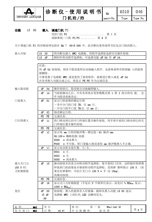
第 1 部 分 - 基 本 参 数 开门速度,mm/s. 关门速度,mm/s. 2 加速度,mm/s . 2 减速度 (正常),mm/s . 2 再开门时减速度,mm/s . 3 加加速度 (速度变化),mm/s . P 增益-速度控制器 (指示值 0.1). I 增益-速度控制器 (指示值 0.01). 显示爬行距离,mm. 爬行速度,mm/s. 强制关门速度,mm/s. 终点位置门的动作力,N. 终点位置门的动作力,N. 加速度预控制系数 (指示值 0.01). 0000 = 加速度预控制不起作用.
W erk Grenzach
教入开始
Technik u. Vertrieb Neuhausen
15 15
00 dF
将诊断仪插入 MW2 电路板,用程序选择轮选择并且操作按钮. 逆时针转动程序选择轮:可选择基本参数功能 dF 20 至 dF bF.
AGV Techn.Inc., Salt Lake City
W alther Rohrposttechnik GmbH, W esterstede (49%)
注意: 用 dF 0d 按按钮,则各个隐设值即自动地编入程序。这意味着所有特别输 入的值将 被删除。 只要更换了电路板 MW2 或是使用了新的软件,就要进行教入或是 dF 0d. 在各项教入功能完成之后,将显示 FE FE 作为完成信息。 输入隐设值 dF dF dF 0d 1d 01 操作按钮后,隐设值自动地编程输入。 当按钮操动之后,只有各项来自变参数模式第 1 第 2 部分的功 能, 会 作为隐设值被设定。 显示门的前缘的额定行程 -非中分门的门宽 TB,以 mm 计。 -中分门的半门宽 TB/2,以 mm 计。 修改额定行程。 完成信息。 将门移动到它的开门终端位置并操作按钮。用手将开着的门移动到它的关 门终端位置并操作按钮。 完成信息。 显示每 mm 行程的脉冲数-额定值-61 脉冲/mm。 36/100 = 概略低限/高限 0000 = 尚未教入 F000 = 不可取,即门宽输入错误或每 mm 脉冲数教入不正确. 显示电动机安装位置,左/右。 0001 = 左 0002 = 右 0000 = 尚未教入 操动按钮并沿某方向转动程序选择轮,使开着的门关闭。这样做时将弹簧 秤装到门的前缘处并继续转动程序选择轮,直到弹 簧秤指示 150 N. (如 果没有弹簧秤,可估计关门力 150 N = 手 动 15kg). 再操动按钮。 完成信息。 显示关门力矩极限值 (不是以 N 牛顿单位显示,而是以 % REAmax 显示, 1000 = REAmax)。 按按钮。教入的值将存入存储器,随即从教入功能 15 00 退出. 电路板 MW2 上的红色 LED 会瞬间发光。
电子温度仪使用说明书
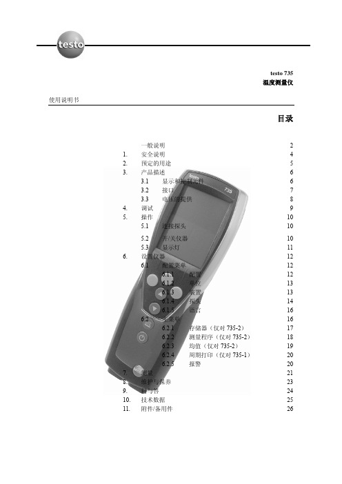
经由三块小型电池(交付时提供的)或可充电电池,或者 USB 电源装置(附件)提供电 压。不能在仪器中给可充电电池充电。
9
4. 调试
本节描述调试本产品所需的步骤。
¾ 撕下显示器上的保护薄膜: > 仔细撕下保护薄膜。
¾ 放入电池/可充电电池和无线模块(附件): 1 松下仪器背面的两个螺丝,并取下电池室的盖子。 2 将电池/可充电电池(3 个小型)放入电池室中。注意电池极性! 3 将无线电模块(附件)推入无线电模块室中,直到其啮合就位。注意导向槽。 4 放回电池室的盖子,按下并上紧两个螺丝。
重要显示
显示 (闪烁)
意义 电池容量(仅对电池/可充电电池的操作): z 电池符号 4 段亮:仪器电池完全充满 z 电池符号都不亮:仪器电池差不多用完 打印功能:将数据发送到打印机 测量通道号:通道 1、通道 2。 如果测量通道是无线电通道,无线电符号及测量通道号均点亮。
3.2 接口
红外线接口
经由仪器头部的红外线接口,可以将测量数据发送到 Testo 打印机。
13
6.1.2 单位
预定义的系统和各个设置选项:
参数 温度
ISO 系统 ℃
US 系统 ℉
各个设置选项 ℃, ℉
¾ 设置单位: √ 打开打开配置菜单,显示 config.(配置)。 1 Units(单位)→ OK 。 2 按 ▲ / ▼ 选择 ISO/US(设置系统)或一个参数(单个设置),并用 OK 确 认。 3 用 ▲ / ▼ 设置单位系统或期望的单位,并用 OK 确认。
注意 目标
条件 步骤 显示文本 控制按钮 功能按钮 结果 交叉参照
提供有用的提示和信息。 表示经由描述的步骤所要达到的目标。步骤编号的地方,你 必须始终遵守给出的顺序! 在按照描述执行一个动作时必须满足的条件。 执行步骤。步骤编号的地方,你必须始终遵守给出的顺序! 在仪器显示器上显示的文本。 按下该按钮。 按下该按钮。 表示上一步的结果。 请参照更广泛或更详细的信息。
英格索兰空压机电脑操作程

按SELECT按钮输入选取中的传感器。按CALIBRATE 按钮起动自动校零程序,或按CANCEL按钮放弃校零并 退到传感器表。
按STATUS或按MAIN MENU钮都可退出校零屏幕。
如D 30秒内不按任何按钮。显示器则退到CURRENT STATUS屏幕。
ALARM HISTORY报警记录
注:用上下箭头按钮在供选参数之间移动,各参数项将以相反的显示模式加亮。
1. 选中加亮的参数项便出现相应的菜单。 2. 选中加亮的参数项将使参数值进入编辑模式,它仅用在以相反
显示模式显示的数值表示。 3. 按上下按钮加减数值。按“Cancel”按钮便退出编辑模式,并
不改变其值。按“Set”按钮就存下新数值,并闪烁表示存盘完 成。 4. 按“Cancel”按钮便退出“校零”模式。按“Calibrate”按钮 便对选中的传感器校零,先要确保机组已停机并完全释放压力。 5. 利用上下箭头按钮可搜索状态表。
1
SEC
Low Ambient 低环境温度
ON/OFF
1
---
Min Cooler Temperature最小冷却器出口 30-150
---
温度
Deg。F
SENSOR CALIBRATION 传感器校零
7,5
READYTOSTART
barg
-SENSOR CALBRATIONSENSOR1AVPT CALIBRATE SENSOR3APT CALIBRATE
Stop Delay Time(停机延迟时 10-30 间) Star-Delta*(星-三角切换时间) 10-20
(Screen)Contrast(屏幕对比 0-10 度)
1
SEC
1
IO及端子板

模拟信号输入模块
AI711-H11使用手册
AI713-S11使用手册AI713-H11使用手册AI711-S11使用手册AI722-S11使用手册
AO711-S11使用手册
AO711-H11使用手册
AO713-H11使用手册
AI731-S11使用手册AO713-S11使用手册DI713-S11使用手册DI715-S11使用手册DI711-S11使用手册
DO712-S11使用手册PI711-S11使用手册
最新部件资料
DI718-S11使用手册DI716-S11使用手册DO711-S11使用手册模拟信号输出模块
数字信号输出模块
数字信号输出模块
脉冲输入模块
DO716-S11使用手册
AM712-S 使用手册
TU031-I0000使用手册
TUA711-GS00使用手册TUA711-DIR32使用手册TUA711-DOR16使用手册TUA711-DOR32使用手册TU731-I0000使用手册TU741-I0000使用手册TUA711-DIO32使用手册TUA711-AIO16使用手册TU735-I0000使用手册TUA711-DIR16使用手册最新部件资料
特殊功能模块
端子板
安全栅底板
TUA712-DOR16使用手册TUA713-DOR16使用手册TU001-R 使用手册AM721-S11使用手册
AM722-S11使用手册TU051-S 使用手册OP051-S 使用手册DEH 模块
TU704-R1100使用手册TU711-R1100使用手册TU713-R 使用手册TU721-R 使用手册。
ICP DAS tGW -735 迷你 Modbus 网关快速入门指南说明书

Quick Startfor tGW-735What’s in the Shipping Package?The package includes the following items:❶tGW-735❷ Quick Start (This Guide)❸Software CD❹DC Connector Power CableInstalling Software on Your PCDecompress eSearch Utility, which can be obtained from eitherthe companion CD-ROM or the web site:/pub/cd/tinymodules/napdos/software/esearch/Connecting the Power and Host PC❶Make sure your PC has workable network settings.Disable or well configure your Windows firewall and Anti-Virus firewallfirst, else the “Search Servers” on Chapter 5 may not work. (Pleasecontact with your system Administrator)❷Make sure the switch is placed in the “Run” mode.❸Connect both the tGW-700 and your PC to the same sub network or the same Ethernet Switch.❹Supply power (PoE or +12 ~ +48 V DC ) to the tGW-700.Connecting the Modbus Devices❶ Connect the Modbus device (Slave, e.g., M-7055D, optional) to your tGW-700, as follows: ❷ Supply power (+10 ~+30 V DC ) to the Modbus device (e.g., M-7055D, Device ID: 1). RS-232 Wiring: RS-485 Wiring:Configuring the Serial PortNote that if you intend to use Internet Explorer, ensure that the cache function is disabledin order to prevent browser access errors, please disable your Internet Explorer cache as follow:(If you are not using IE browser, please skip this step.)Step 1: Click “Tools” >> “Internet Options...” in the menu items.Step 2: Click the “General” tab and then click the “Settings...” button in Temporary Internet files frame. Step 3: Click the “Every visit to the page” and then click the “OK” button in Settings box and Internet Options box.❶Enter the password (use the defaultpassword “admin”) in the Login passwordfield and click the “Submit” button.❶❷Click the “Port1” tab to display the Port1 Settings page.❸Select the same Modbus protocol for tGW-700 in according to the protocol of the Modbus device (e.g., Modbus RTU/ASCII), and click the “Submit” button to save your settings.❷❸Self-Test❶In the eSearch Utility, select the “Modbus TCP Master” item from the “Tools” menu to open the Modbus TCP Master Utility.❷In the Modbus TCP Modbus Utility, enter the IP address of tGW-700 and then click the “connect” button to connect the tGW-700.Successful Testing❸Refer to “Protocol Description” section and type the command in the “Command” field then click the “Send command” button. If the response data is correct, it means the test is success.e.g., If M-7000 Modbus device ID = 1, you send “1 2 0 0 0 6 1 2 0 0 4” for reading D/I value, you receive response “1 2 0 0 0 4 1 2 1 0” as shown below.❸Related InformationtGW-700 product page:/tgw_735.html。
7350系列电力传输安装、维护和零部件手册说明书

For other service manuals visit our website at:/service_manuals.aspDORNER MFG. CORP .INSIDE THE USA OUTSIDE THE USAP .O. Box 20 • 975 Cottonwood Ave.TEL: 1-800-397-8664TEL: 262-367-7600Hartland, WI 53029-0020 USA FAX: 1-800-369-2440FAX: 262-367-5827851-687 Rev. C7350 Series Power TransferInstallation, Maintenance and Parts ManualDorner Mfg. Corp.2851-687 Rev. C7350 Series Power TransferTable of ContentsIntroduction......................................................................... 2Warnings – General Safety.................................................. 3Product Description............................................................. 4Specifications...................................................................... 47350 Power Transfer........................................................ 4Installation........................................................................... 5Required Tools................................................................. 5Power Transfer Assembly................................................ 5Drive Package Installation............................................... 9Preventive Maintenance and Adjustment.......................... 10Required Tools............................................................... 10Checklist .. (10)Cleaning (10)Lubrication..................................................................... 10Maintaining the Conveyor Belt...................................... 10Troubleshooting.......................................................... 10Timing Belt Replacement............................................... 11Belt Replacement ........................................................... 11Roller Replacement........................................................ 12Bearing Replacement ..................................................... 14Position Adjustment....................................................... 15Service Parts....................................................................... 16Power Transfer Components.......................................... 16Return Policy. (18)IntroductionUpon receipt of shipment:•Compare shipment with packing slip. Contact factory regarding discrepancies.•Inspect packages for shipping damage. Contact carrier regarding damage. Accessories may be shipped loose.• See accessory instructions for installation.The Dorner Limited Warranty applies.Dorner 7350 Series conveyors have patents pending.Dorner reserves the right to make changes at any time without notice or obligation.Dorner has convenient, pre-configured kits of Key Service Parts for all conveyor products. These time saving kits are easy to order, designed for fast installation, and guarantee you will have what you need when you need it. Key Partsand Kits are marked in the Service Parts section of this manual with the Performance Parts Kits logo .CAUTIONSome illustrations may show guardsremoved. DO NOT operate equipment without guards.851-687 Rev. C3Dorner Mfg. Corp.7350 Series Power TransferWarnings – General SafetySEVERE HAZARD!KEEP OFF CONVEYORS. Climbing, sitting, walking or riding on conveyor will result in death or serious injury.EXPLOSION HAZARD!•DO NOT OPERATE CONVEYORS IN AN EXPLOSIVE ENVIRONMENT. The electric gearmotor generates heat and could ignite combustible vapors.•Failure to comply will result in death or serious injury.WARNINGCRUSH HAZARD!•DO NOT place hands or fingers inside the conveyor while it is running.•DO NOT wear loose garments whileoperating the conveyor. Loose garments can become caught up in the conveyor.•Failure to comply could result in serious injury.WARNINGCRUSH HAZARD!•SUPPORT CONVEYOR SECTIONS PRIOR TO LOOSENING STAND HEIGHT OR ANGLE ADJUSTMENT SCREWS.•Loosening stand height or angleadjustment screws may cause conveyor sections to drop down, causing serious injury.WARNINGSEVERE HAZARD!LOCK OUT POWER before removing guards or performing maintenance. Exposed moving parts can cause serious injury.WARNINGBURN HAZARD!DO NOT TOUCH the motor while operating, or shortly after being turned off. Motors may be HOT and can cause serious burn injuries.WARNINGPUNCTURE HAZARD!Handle drive shaft keyway with care. It may be sharp and could puncture the skin, causing serious injury.WARNINGSEVERE HAZARD!•Dorner cannot control the physicalinstallation and application of conveyors. Taking protective measures is the responsibility of the user.•When conveyors are used in conjunction with other equipment or as part of a multiple conveyor system, CHECK FOR POTENTIAL PINCH POINTS and other mechanical hazards before system start-up.•Failure to comply could result in serious injury.Dorner Mfg. Corp.4851-687 Rev. C7350 Series Power TransferProduct DescriptionRefer to (Figure 1) for typical components.Figure 1Specifications7350 Power Transfer1Gearmotor 2Power T ransfer Belt 3Driven Pulley 4T ensioner 5Timing Belt 6Drive Pulley 7Conveyor1732546Conveyor Belt Width Flat belt and curve end drive conveyors4” (102 mm) - 36” (914 mm) wide in 2” (51 mm) incrementsMaximum Belt Speed175 ft/minute (53 m/minute)851-687 Rev. C5Dorner Mfg. Corp.7350 Series Power TransferInstallationFigure 3b.For assembly on drive tail: Locate conveyor drive shaft (Figure 4,item 1). Remove two lower bolts (Figure 4,item 2).Figure 4SEVERE HAZARD!1221Dorner Mfg. Corp.6851-687 Rev. C7350 Series Power TransferInstallation2.Install bent transfer plate (Figure 5,item 1) onto side of frame with two bolts (Figure 5,item 2) (just removed). Tighten bolts.Figure 53.On opposite side of conveyor, remove three bolts (Figure 6,item 1).Figure 64.Insert three M6x20 bolts (Figure 7,item 1) through transfer plate (Figure 7,item 2), and install spacer (Figure 7,item 3) for each bolt (between transfer plate and conveyor).Figure 75.Tighten all three bolts (Figure 8,item 1) securing transfer plate (Figure 8,item 2) to conveyor frame.Figure 86.Install timing belt cover bracket (Figure 9,item 1) with two M6 bolts (Figure 9,item 2) to transfer plate.Figure 97.Install power transfer belt assembly (Figure 10,item 1) with flange bolts (Figure 10,item 2) installed onto slots (Figure 10,item 3) on each side bracket.Figure 1012123121213123851-687 Rev. C7Dorner Mfg. Corp.7350 Series Power TransferInstallation8.To adjust height, place level (Figure11,item 1) orstraight edge to level power transfer assembly (Figure 11,item 2) with conveyor belt (Figure 11,item 3). Tighten two bolts (Figure 11,item 4) to secure position.Figure 119.To adjust location, place level (Figure 12,item 1) or straight edge to level power transfer assembly (Figure 12,item 2) with conveyor belt(Figure 12,item 3). Be certain that there is a minimum 1/8 - 1/4 in. distance (Figure 12,item 4) between power transfer and conveyor belt, and tighten three bolts (Figure 12,item 5) to secure position.Figure 12Figure 1310.Install key (Figure 14,item 1) onto conveyor shaft(Figure 14,item 2).Figure 1411.Install drive pulley (Figure 14,item 3) onto end ofconveyor shaft.321414523NOTEBefore running power transfer, be certain that belts (Figure 13,item 1) are not riding on spacers (Figure 13,item 2).WARNINGDrive shaft keyways may be sharp.HANDLE WITH CARE.21312Dorner Mfg. Corp.8851-687 Rev. C7350 Series Power TransferInstallation12.Install key (Figure 15,item 1) onto power transferassembly shaft (Figure 15,item 2).Figure 1513.Install driven pulley (Figure 15,item 3) onto end ofpower transfer assembly shaft.14.Wrap timing belt (Figure 16,item 1) around drivenpulley (Figure 16,item 2) and drive pulley (Figure 16,item 3).Figure 1615.Install tensioner (Figure 17,item 1) with washer(Figure 17,item 2) onto bracket (Figure 17,item 3) with screw (Figure 17,item 4) and nut (Figure 17,item 5).Figure 17ing a straight edge, align driven pulley(Figure 18,item 1) with drive pulley(Figure 18,item 2) and tensioner (Figure 18,item 3), and tighten drive and driven pulley set screws.Figure 18NOTEY ou may need to slide driven pulley (Figure 16,item 2) off of shaft to install timing belt (Figure 16,item 1).123132125432137350 Series Power Transfer Installation17.Depending upon belt travel (direction A or B), locatetiming belt tensioner (Figure19,item1) as shown.Figure1918.Tension timing belt to obtain 1/8” (3 mm) deflection for6 lb (3 Kg) of force at timing belt mid-point(Figure20,item1). Tighten tensioner screw(Figure20,item2) to 110 in-lb (12 Nm).Figure20 19.Install cover (Figure21,item1) with two (2) screws(Figure21,item2). Tighten screws to 35 in-lb (4 Nm).Figure21Drive Package InstallationFor detailed assembly instructions, refer to the appropriate Drive Packages Manual:•851-679 Side Mount 90° Drive Package•851-681 Bottom Mount 90° Drive Package•851-682 Bottom Mount Parallel Shaft Drive Package1.Attach the motor (Figure22,item1) to the conveyoroutput shaft (Figure22,item2).Figure2211BA12121 2851-687 Rev. C9Dorner Mfg. Corp.Dorner Mfg. Corp.10851-687 Rev. C7350 Series Power TransferPreventive Maintenance and AdjustmentRequired Tools•Level • 6 mm wrench •8 mm wrench •10 mm wrench •3/32” hex wrench •5/32” hex wrenchChecklist•Keep service parts on hand. Refer to the "Service Parts" section starting on page 16 for recommendations.•Replace any worn or damaged parts.CleaningLubricationNo lubrication is required. Replace bearings if worn.Maintaining the Conveyor BeltTroubleshootingInspect conveyor belt for: •Surface cuts or wear •SkippingDamage to belt links or rods, surface cuts and /or wear indicate:•Sharp or heavy parts impacting belt •Jammed parts •Accumulated dirt•Foreign material inside the conveyor •Improperly positioned accessories Skipping indicates: •Excessive load on belt•Worn spindle or impacted dirt on drive spindleNOTEProper conveyor application, cleaning, and sanitation are the responsibility of the end user.CAUTION CAUTIONDorner recommends cleaning all the “foodzones” prior to placing conveyor into service. Ensure adequate access is provided forcleaning and servicing equipment so that the required level of hygiene can be maintained.WARNINGSEVERE HAZARD!LOCK OUT POWER before removing guards or performing maintenance. Exposed moving parts can cause serious injury.851-687 Rev. C11Dorner Mfg. Corp.7350 Series Power TransferPreventive Maintenance and AdjustmentTiming Belt Replacement1.Remove two (2) screws(Figure 23,item 1) and cover (Figure 23,item 2).Figure 232.Loosen tensioner screw (Figure 24,item 1), and slide tensioner (Figure 24,item 2) downward.Figure 243.Slide driven pulley (Figure 24,item 3) outward and remove timing belt (Figure 24,item 4) from driven pulley and drive pulley (Figure 24,item 5).4.Replace the old belt with a new one. Refer to install procedure in “Power Transfer Assembly” on page 5.Belt Replacement1.Remove timing belt. Refer to “Timing Belt Replacement” on page 11.2.Loosen two flanged screws (Figure 25,item 1).Figure 253.Lift power transfer assembly (Figure 23,item 2) from side plates (Figure 23,item 3).4.Remove screw (Figure 26,item 1) and loosen screw (Figure 26,item 2). Shaft assembly will collapse, removing tension from the power transfer belts.Figure 26WARNINGSEVERE HAZARD!LOCK OUT POWER before removing guards or performing maintenance. Exposed moving parts can cause serious injury.2145321WARNINGSEVERE HAZARD!LOCK OUT POWER before removing guards or performing maintenance. Exposed moving parts can cause serious injury.113221Dorner Mfg. Corp.12851-687 Rev. C7350 Series Power TransferPreventive Maintenance and Adjustment5.Remove belts (Figure 27,item 1) from power transfer assembly (Figure 27,item 2).Figure 276.Replace the old belts with a new belts.7.Lower inner power transfer bracket (Figure 28,item 1) from outer bracket (Figure 28,item 2), until belts are tight.Figure 288.Tighten screw (Figure 28,item 3), and install and tighten screw (Figure 28,item 4).9.Place level (Figure 29,item 1) or straight edge to level power transfer assembly (Figure 29,item 2) with conveyor belt (Figure 29,item 3).Figure 2910.Tighten bolts(Figure 29,item 4) to secure position.Roller Replacement1.Remove belts. See “Belt Replacement” on page 11.2.While holding onto inner nut (Figure 30,item 1), remove outer nut (Figure 30,item 2).Figure 30123412WARNINGSEVERE HAZARD!Exposed moving parts can cause severe injury. LOCK OUT POWER before removing guards or performing maintenance.321421851-687 Rev. C13Dorner Mfg. Corp.7350 Series Power TransferPreventive Maintenance and Adjustment3.Slide rod (Figure 31,item 1) inward and remove the inner nut (Figure 31,item 2).Figure 314.Remove rod (Figure 32,item 1) and rollers (Figure 32,item 2). Figure 325.Repeat on opposite side.6.Install rollers onto rod, reverse of removal.7.Install inner nut (Figure 33,item 1) onto rod (Figure 33,item 2).Figure 338.Install rods (Figure 34,item 1) so they remain flush with power transfer bracket surface (Figure 34,item 2).Figure 349.While holding onto inner nut (Figure 35,item 1), install and tighten outer nut (Figure 35,item 2).Figure 3510.Install four belts. See “Belt Replacement” on page 11.1221211221Dorner Mfg. Corp.14851-687 Rev. C7350 Series Power TransferPreventive Maintenance and AdjustmentBearing Replacement1.Remove four belts. See “Belt Replacement” on page 11.2.Rotate assembly upside down on conveyor.3.Remove screw (Figure 36,item 1). Repeat on opposite side.Figure 364.Remove shaft assembly (Figure 37,item 1) from power transfer frame (Figure 37,item 2).Figure 375.Remove bracket (Figure 38,item 1) from each side of shaft assembly by sliding it off the bearing. Be certain to note location and orientation of left and right sides.Figure 386.Loosen set screws (Figure 39,item 1) from bearing (Figure 39,item 2).Figure 397.Remove bearing (Figure 40,item 1) from shaft (Figure 40,item 2).Figure 408.Install new bearing on each side.WARNINGSEVERE HAZARD!Exposed moving parts can cause severe injury. LOCK OUT POWER before removing guards or performing maintenance.11212112851-687 Rev. C15Dorner Mfg. Corp.7350 Series Power TransferPreventive Maintenance and Adjustment9.Center shaft assembly, so that there is equal space between each bracket (Figure 41,item 1) and roller (Figure 41,item 2). Tighten set screws (Figure 41,item 3).Figure 4110.Install belts. Refer to “Belt Replacement” on page 11.Position Adjustment1.To adjust height, place level (Figure 42,item 1) or straight edge to level power transfer assembly (Figure 42,item 2) with conveyor belt (Figure 42,item 3). Tighten two bolts (Figure 42,item 4) to secure position.Figure 422.To adjust location, place level (Figure 43,item 1) or straight edge to level power transfer assembly (Figure 43,item 2) with conveyor belt(Figure 43,item 3). Be certain that there is a minimum 1/8 - 1/4 in. distance (Figure 43,item 4) between power transfer and conveyor belt, and tighten three bolts (Figure 43,item 5) to secure position.Figure 43Figure 4432113214NOTEBefore running power transfer, be certain that belts (Figure 44,item 1) are not riding on spacers (Figure 44,item 2).1452321Dorner Mfg. Corp.16851-687 Rev. C7350 Series Power TransferService PartsNOTEFor replacement parts other than those shown in this section, contact an authorized Dorner Service Center or the factory. Key Service Parts and Kits are identified by the Performance Parts Kits logo . Dorner recommends keeping these parts on hand.49272525851-687 Rev. C17Dorner Mfg. Corp.7350 Series Power TransferService PartsItem Part NumberDescription1509838Cover2960506MSS Hex Head Cap Screw, M5-.80 x 6 mm 3509837Cover Bracket4814-097Belt, for use with 48 Tooth Pulley 814-415Belt, for use with 30 Tooth Pulley 814-108Belt, for use with 60 Tooth Pulley 5509855Pulley, 48 Tooth 509859Pulley, 30 Tooth 509860Pulley, 60 Tooth 6509856Pulley, 22 Tooth 7912-108SS Key8960840MSS Hex Head Cap Screw, M8-1.25 x 40 mm 9802-046Bearing Cam10450445Cam Spacer 11202390M Cam Nut12911-208Washer, 0.3125" 13509839Aluminum Spacer14960616MSSF Hex Head Cap Screw, M6-1.00 x 16 mm 15509833T ransfer Plate16960510MSS Hex Head Cap Screw, M5-.80 x 10 mm 17960620MSS Hex Head Cap Screw, M6-1.00 x 20 mm18960625MSS Hex Head Cap Screw, M6-1.00 x 25 mm 19911-201Washer, 0.25"20509851Spindle Guard21509831Bearing Retaining Block, Left Hand 22509846-WW Frame Assembly, for Straight Conveyors 509847-WWFrame Assembly,for Curve Conveyors23509840-WW Roller Shaft for Straight Conveyors 509841-WW Roller Shaft for Curve Conveyors 24509849-LLL Plastic Spacer 25*501087Roller, 0.5" x 1.06"26509836Support Plate27*509850-100Timing Belt, 100 mm wide 509850-075Timing Belt, 75 mm wide 509850-050Timing Belt, 50 mm wide 509850-025Timing Belt, 25 mm wide28990601MSS Hex Nut 29509832Bearing Retaining Block, Right Hand 30509835Bent Transfer Plate, Right Hand509834Bent Transfer Plate, Left Hand31912-080SS Key 32807-1852Retaining Ring 33802-180Bearing34509842-WW Pulley for Straight Conveyor 509843-WW Pulley for Curve Conveyor35960820MSSHex Head Cap Screw,M8-1.25 x 20 mm36735PT -WW Power T ransfer Kit(Includes items 23, 24, 25, 28, and 33)WW = Conveyor width reference: 04 − 36 in 02 increments LLL = Spacer Length in inches with 3 decimal places.Example: Spacer Length = 0.25" LLL = 250*See table for timing belt and roller quantities per conveyor width.Timing Belt and Roller Quantity Chart Width Roller Quantity - Item #25Timing Belt Quantity - Item #274”8509850-0756”12509850-100 & 509850-0508”16509850-100 & 509850-07510”20509850-100 (x2) & 509850-02512”24509850-100 (x2) & 509850-07514”28509850-100 (x3) & 509850-02516”32509850-100 (x3) & 509850-07518”34509850-100 (x4) & 509850-02520”38509850-100 (x4) & 509850-07522”42509850-100 (x5) & 509850-02524”44509850-100 (x5) & 509850-07526”48509850-100 (x6) & 509850-02528”52509850-100 (x6) & 509850-07530”56509850-100 (x7)32”60509850-100 (x7) & 509850-05034”64509850-100 (x8)36”68509850-100 (x8) & 509850-050851-687 Rev. C Printed in U.S.A.Dorner Mfg. Corp. reserves the right to change or discontinue products without notice. Allproducts and services are covered inaccordance with our standard warranty. All rights reserved. © Dorner Mfg. Corp. 2010DORNER MFG. CORP .975 Cottonwood Ave., PO Box 20 Hartland, WI 53029-0020 USA TEL 1-800-397-8664 (USA)FAX 1-800-369-2440 (USA)Internet: Outside the USA:TEL 1-262-367-7600FAX 1-262-367-5827Return PolicyReturns must have prior written factory authorization or they will not be accepted. Items that are returned to Dorner without authorization will not be credited nor returned to the original sender. When calling for authorization, please have the following information ready for the Dorner factory representative or your local distributor: and address of customer.2.Dorner part number(s) of item(s) being returned.3.Reason for return.4.Customer's original order number used when ordering the item(s).5.Dorner or distributor invoice number (if available, part serial number).A representative will discuss action to be taken on the returned items and provide a Returned Goods Authorization (RMA) number for reference. RMA will automatically close 30 days after being issued. To get credit, items must be new andundamaged. There will be a return charge on all items returned for credit, where Dorner was not at fault. It is the customer’s responsibility to prevent damage during return shipping. Damaged or modified items will not be accepted. The customer is responsible for return freight.Returns will not be accep ted after 60 days from original invoice date. The return charge covers inspection, cleaning,disassembly, disposal and reissuing of components to inventory. If a replacement is needed prior to evaluation of returned item, a purchase order must be issued. Credit (if any) is issued only after return and evaluation is complete.Dorner has representatives throughout the world. Contact Dorner for the name of your local representative. Our Customer Service Team will gladly help with your questions on Dorner products.For a copy of Dorner's Warranty, contact factory, distributor, service center or visit our website at .For replacement parts, contact an authorized Dorner Service Center or the factory.Product TypeStandard ProductsEngineered to order partsProduct LineConveyors Gearmotors & Mounting Packages Support Stands Accessories Spare Parts (non-belt)Spare Belts - Standard Flat Fabric Spare Belts - Cleated & Specialty FabricSpare Belts -Plastic Chain All equipment and parts110030% return fee for all products except:50% return fee for conveyors with modular belt,cleated belt or specialty beltsnon-returnablecase-by-case22002200 Modular Belt 2200 Precision Move 23002300 Modular Belt 32003200 LPZ3200 Precision Move 4100520053006200Controls 7200 / 730050% return fee for all products7350non-returnable736074007600。
台湾巨控 A-1 系列远程 I O 模块 用户手册说明书

台湾巨控A-1系列远程I/O模块用户手册V1.13Edit:2018/01/30目录一、Modbus协议简介 (3)1、Modbus协议主从响应过程 (3)2、Modbus的寄存器区和常用功能码 (4)二、Modbus协议帧格式 (4)1、Modbus RTU (4)2、Modbus ASCII (5)3、Modbus TCP (5)三、I/O模块的基本使用及参数配置方法 (5)1.模块的基本硬件连接 (5)2.模块参数修改 (5)3.模拟量输入模块配置说明(A-1019/A-1219/A-1819) (8)四、调试及上位机通讯 (9)1.调试说明 (9)2.模块与上位机软件通讯 (9)五、Modbus协议地址表 (18)1.A-1057/1058/1068/1069/1051/1055/1055S/1060地址表 (18)2.A-1010地址表 (19)3.A-1012地址表 (20)4.A-1019地址表 (23)5.A-1212地址表 (25)6.A-1219地址表 (28)7.A-1251/A-1255/A-1255S/A-1269/A-1260地址表 (32)8.A-1812地址表 (34)9.A-1812地址表 (36)10.A-1851/A-1855/A-1855S/A-1869/A-1860地址表 (39)本文包含了台湾巨控远程I/O 模块的Modbus 协议简介、寄存器地址表,I/O 模块的一般使用以及与其它设备通讯调试等。
一、Modbus 协议简介Modbus 协议是由Modicon 公司开发设计的一种通信传输协议,在1979年该公司成为施耐德自动化(Schneider Automation)部门的一部分。
现在Modbus 已经是在工业领域被广为应用的最流行、最广泛的真正开放、标准的网络通讯协议。
此协议支持传统的RS-232、RS-422、RS-485和以太网设备。
许多工业设备,包括PLC 、DCS 、智能仪表、I/O 模块等都在使用Modbus 协议作为其通讯标准。
万特735 操作说明书 中文

万特735 操作说明书中文1、电源开关(POWER)揿入时接通电源。
注意:使用蓄电池直流电源供电时,即使机器电源开关断开(即未揿入时),机内功率放大器仍加上电。
因此,电源线上必须加接一个电源闸刀开关,电台不工作时,闸刀开关拉开,则机器彻底断开电源。
1.音量开关(AF)增大或减小音量。
2.静噪开关(SQL)有噪音时,显示版上有(RECV)显示。
平时工作时,要旋到有显示。
扫描工作时,要旋到刚好显示消失。
3.工作方式开关:有单边带(SSB),连续波即等幅板(CW),调幅(AM)和调频(FM)等四种工作方式可供选择。
渔业生产用通信一般是用单边带工作方式。
频率在7MHZ以下用下边带(LSB)。
其它用上边带(USB)。
揿入(SSB)开关时,显示版上显示出USB (上边带)或LSB(下边带)。
4.调谐控制轮。
当要改变机器频率时可配合“KHZ”“MHZ”“HAM”三个开关使用。
5.KHZ开关。
揿入此开关,转动调谐轮,频率以1KHZ步进,以便调节频率。
6.MHZ开关。
揿入此开关,转动调谐轮,频率以1MHZ步进,以便调节频率。
7.HAM开关。
揿入此开关,显示的频率为体育业余频率,也可配合调谐轮调节频率。
9.频率锁定开关(LOCK)揿入此键,其工作频率被锁定,也可配合工作方式扫描用。
10VFO开关。
此开关为可变频率振荡器,即压控振荡器。
它有两个VFOA和VFOB,可分别存入频率和工作方式,异频工作时用。
11.VFO等位开关(A=B)揿入此开关,可使两个压控振荡器VFOA和VFOB的工作方式和频率相同,同频工作时用。
12.存贮器读出开关。
揿入此开关,“MEMO”显示出来,VFOA和VFOB消失,这时按向上或向下开关,可以选取所需要的工作频道进行工作(如原来把一个频率存入5频道,这时只要选取“MEMO”如下方出现“5”字头,则原来存入的那个频率和工作方式就会显示出来。
13.存贮频道增加/减少(M-CH UP/DOWN)在显示“MEMO”的情况下,增加或减少按此开关,可以选择工作频道。
BEKO HMM7350X 混合器使用手册说明书

NOTICEMARQUE: BEKO REFERENCE: HMM7350X CODIC: 4377605Merci de bien vouloir lire ce manuel d'utilisation avant de commencer!Chère cliente, cher client,Merci d’a voir choisi les produits Beko. Nous espérons que ce produit, fabriqué dans des installations modernes et soumis à un processus de contrôle qualité rigoureux, vous offre les meilleures performances possibles. C’e st pourquoi nous vous recommandons, avant d’u tiliser ce produit, de lire attentivement ce manuel et tous les autres documents fournis et de les conserver soigneusement pour toute consultation future. Si vous confiez le produit à quelqu’u n d’a utre, n’o ubliez pas de lui remettre également le manuel d’u tilisation. Veillez à bien respecter les consignes et les instructions figurant dans le manuel d’u tilisation.Signification des symbolesCe produit a été fabriqué dans des usines écologiques et modernes.Ne contient pas de PCB.Fabriqué en P.R.C.Cet appareil est conforme à la directive DEEE.matière de sécurité etd’environnement 24 1.1 Consignes générales de sécurité. . . . . . . . . 24 1.2 Conformité avec la directive DEEEet mise au rebut des produits usagés . . . 271.3 Information sur l'emballage . . . . . . . . . . . . . . 282 Votre Mixeur 29 2.1 Vue d'ensemble . . . . . . . . . . . . . . . . . . . . . . . . . . 292.2 Données techniques . . . . . . . . . . . . . . . . . . . . . 293 Fonctionnement 30 3.1 Utilisation prévue . . . . . . . . . . . . . . . . . . . . . . . . 30 3.2 Première utilisation . . . . . . . . . . . . . . . . . . . . . . 30 3.3 Battre / Mixer . . . . . . . . . . . . . . . . . . . . . . . . . . . . 30 3.3.1 Batteurs . . . . . . . . . . . . . . . . . . . . . . . . . . . . . . . . .31 3.3.2 Spirales du mixeur. . . . . . . . . . . . . . . . . . . . . . .31 3.4 Bouton TURBO. . . . . . . . . . . . . . . . . . . . . . . . . . . .31 3.5 Astuces pour faire des économiesd'énergie . . . . . . . . . . . . . . . . . . . . . . . . . . . . . . . . .31 4 Nettoyage et entretien 32 4.1 Nettoyage. . . . . . . . . . . . . . . . . . . . . . . . . . . . . . . . 32 4.2 Rangement . . . . . . . . . . . . . . . . . . . . . . . . . . . . . . 32 4.3 Manipulation et transport. . . . . . . . . . . . . . . . 32aident à se prémunir contre les risques de dommages corporels ou de dégâts matériels.Le non-respect de ces consignes annule la garantie.1.1 Consignes générales desécurité•Cet appareil est conçu selon les normes internationales de sécurité.•Cet appareil peut être utilisé par les personnes à capacités physiques, sensorielles ou mentales réduites ou qui manquent d’expérience et de connaissances, à condition qu'elles soient supervisées ou qu'e lles aient reçues les consignes concernant l'utilisation sûre de l’appareil et assimilées les dangers encourus. L es enfants ne doivent pas jouer avec l’appareil. Les travaux d'e ntretien et de nettoyage ne doivent pas être effectués par des enfants.•Cet appareil ne peut pas être utilisé par les enfants. •Maintenez l'a ppareil et le câble hors de la portéel’a ppareil lui-même est endommagé. Contactez un service agréé.•Débranchez l'appareil lorsqu'il est laissé sans surveillance, lorsque vous installez/retirez les accessoires ou avant de le nettoyer. •Utilisez uniquement des pièces d’o rigine ou pièces recommandées par le fabricant.•N’e ssayez pas de démonter l’a ppareil. •Assurez-vous que votre source d’alimentation électrique soit conforme aux informations spécifiées sur la plaque signalétique de votre appareil.•N’u tilisez pas de cordon prolongateur avec l’a ppareil. •Ne tirez pas sur le câble d’a limentation de l’a ppareil pour le débrancher de l’a limentation.•Débranchez l'appareil avant le nettoyage, le démontage ou le remplacement des accessoires et attendez qu'il soit à l'a rrêt complet.•Ne touchez jamais la prise électrique avec les mainschauds.•Retirez les os et les cailloux des aliments pour éviter d'e ndommager les lames et l'a ppareil.•Cet appareil n'e st pas adapté pour hacher des aliments secs ou durs.•Pour éviter toute surchauffe, ne faites pas fonctionner les batteurs de manière continue pendant plus de 10 minutes. L aissez-le refroidir pendant 5 minute entre chaque utilisation de 10 minutes.•Pour éviter toute surchauffe, ne faites pas fonctionner l'a ppareil de manière continue pendant plus de 2 minutes. Laissez-le refroidir pendant 1 minute entre chaque utilisation de 2 minutes. •Suivez toutes les instructions afin d'éviter des blessures dues à un mauvais usage de l'a ppareil. •Après le nettoyage, séchez l'a ppareil et tous ses composants avant de le brancher sur le secteur et d'y ajouter les accessoires.la prise d'a limentation électrique dans l'e au ou tout autre liquide. •Ne faites jamais fonctionner ou n'installez aucun composant de cet appareil au-dessus ou à proximité de surfaces chaudes. •Si vous conservez le matériel d’e mballage, tenez-le hors de la portée des enfants.1.2 Conformité avec la directive DEEE etmise au rebut des produits usagés» avec des pièces et du matériel de qualité supérieure, susceptibles d’être réutilisés aux fins de recyclage. Par conséquent, à la fin de sa durée de vie, il ne doit pas être mis au rebut aux côtés de déchets domestiques ordinaires. Au contraire, il doit être éliminé dans un point de collecte réservé au recyclage d'appareils électriques et électroniques. Consultez les autorités locales de votre région pour connaître les points de recyclage. Participez à la protection de l'environnement et des ressources naturelles grâce au recyclage des produits usagés.d’éléments d’emballage que vous indiquera l’autorité locale dont vous dépendez.Les valeurs indiquées sur les inscriptions apposées sur votre produit ou les autres documents fournis avec le produit sont des valeurs obtenues en conditions de laboratoire, conformément aux normes en vigueur. Ces valeurs peuvent varier selon l’utilisation de l’appareil et les conditions environnantes.1. Unité du moteur2. Fentes pour accessoires3. B outon de relâchement des accessoires4. B outon de réglage de la vitesse5. Bouton TURBO6. Batteurs (6a/6b)7. S pirales de pétrissage (7a/7b) 2.2 Données techniques Cet appareil est con-forme aux Directives européennes 2004/108/CE, 2006/95/CE, 2009/125/CE et 2011/65/UE. Tension : 220-240 V, 50/60 Hz Puissance : 350 W Sous réserve des modifications techniques et de conception.234517a 7b6a 6bprévueuniquement pour une utilisationdomestique ; il ne convient pas àun usage professionnel.3.2 PremièreutilisationNettoyez les pièces de l'appareilavant la première utilisation (sereporter au paragraphe 4.1).3.3 Battre / Mixer1.battage et de mixage dans lessocles (2) situés sous le mixeur.battage dotés d'un anneau rond(6a) et les spirales de mixage(7a) dans le grand socle et lesautres spirales de battage (6b)et de pétrissage (7b) dans le4. Tenez l'appareil sur le récipientdans lequel vous avezultérieurement préparé lesingrédients à battre ou à mixeren position inclinée et en visantle fond du récipient.progressivement le bouton(4) vers le niveau de vitessesouhaité.6. L orsque le battage/mixage est terminé, déplacez le bouton (4) vers le point “0” et attendez8. Appuyez sur le bouton de relâchement des accessoires (3)•Utilisez toujours les deux batteurs.•es casseroles revêtues de Téflon peuvent être rayées.•Utilisez pour mixer des ingrédients liquides tels que des cakes, des sauces ou de la soupe.3.3.2 Spirales du mixeur•Utilisez toujours les spirales du mixeur.•es casseroles revêtues de Téflon peuvent être rayées.•Utilisez pour pétrir de la pâte. 3.4 Bouton TURBOL orsque vous avez besoin d'une vitesse encore plus élevée, main-tenir le bouton TURBO et relâchezlorsque vous n'en avez plus besoin.3.5 Astuces pour faire des économies d'énergieMettez l’appareil hors tension et débranchez-le.l'appareil avant de le nettoyer.2. Assurez-vous que les spiralesde battage et de mixage sontà l'arrêt complet et retirez lesaccessoires.3. Essuyez l'unité du moteur del'appareil (1) avec un chiffonhumide.4. Les accessoires retirés peuventêtre lavées avec une éponge etdu détergent pour lave-vaisselle.5. Séchez tous les éléments de•Si vous ne comptez pas utiliservotre appareil pendant uncertain temps, veuillez le rangersoigneusement.•Débranchez l'appareil avant de lesoulever.•Conservez l'appareil dans unendroit frais et sec.•Maintenez l'appareil et le câblehors de la portée des enfants.4.3 Manipulation ettransport•Pendant la manipulation etle transport, portez toujoursl'appareil dans son emballaged'origine. L'emballage del'appareil le protège desdommages physiques.•Ne placez pas de charge lourdesur l'appareil ou sur l'emballage.Cela pourrait l'endommager.•Toute chute de l'appareil peutle rendre non opérationnelou l'endommager de façonpermanente.。
中控ECS-700硬件IO模块TU735-I0000使用手册

安全栅底板 TU735-I00001概述TU735-I0000为8路隔离式安全栅底板,可供一对冗余或1块AO711模块使用;TU735-I0000可以安装8个MTL4000系列或SB4000系列模拟量输出型隔离栅。
(4~20)mA信号从卡件经过DB37线到TU735-I0000底板,后经过隔离栅隔离后输出到现场。
2技术特性表 2-1 性能指标模块类型TU735-I0000指标项指标说明备注通道数8点配合的隔离栅类型MTL4046C(输入、输出、电源三隔离)SB4046-EX(输入、输出、电源三隔离)系统侧4 mA ~20mA 输入,本安侧4mA ~20mA输出,带HART供电电压 24VDC(冗余)带熔断式保险丝规格153.5mm×151.5 mm工作温度0℃~60℃3使用说明3.1安全栅底板外观图TU735-I0000结构外形如图3-1所示。
模块通过J1输出8个信号到隔离栅。
图3-1 TU735-I0000端子板结构外形图3.2接插件说明TU735-I0000接插件说明如表3-1所示:表3-1 TU735-I0000接插件说明标号说明J1 DB37数据连线插座J2 供电电源连线端子F1 保险丝3.3安全栅底板支持的隔离栅种类表 3-2 TU735-I0000支持的隔离栅种类隔离栅部件厂商备注MTL4046C MTL系统侧4 mA ~20mA 输入,本安侧4 mA ~20mA输出,带HARTSB4046-EX 辰竹系统侧4 mA ~20mA 输入,本安侧4 mA ~20mA输出,带HART3.4端子定义TU735-I0000接线端子说明如表 3-3所示。
隔离栅接入外配电时,可从J2 的1、2号端子或者3、4号端子接入一路外部24V电源。
“24V A”和“24VB”表示接外部24V正端,“VS-”表示接外部24V负端,当需要接入冗余的外配24V电源时,可同时从1、2号端子和3、4号端子分别接入。
SB7350 十组灯泡输出控制IC使用说明

1M 104
104
1 VDD RESET 16
2 GO
L6 15
3 ALLON
L5 14
4 RT
L4 13
5 SB
L3 12
6 RC
L2 11
7 MODE
L1 10
8 VSS FLASH 9
SB7350-2
{ L5 { L4 { L3 { L2 { L1
L1
L2
L3
L4
L5
Q1
Q2
Q3
Q4
Q5
L1 {
1 2 3 4 56
7 8 9 10
RESET VDD GO ALLON RT SB RC MODE VSS FLASH
2. 6 輸出(16P DIP)
RESET L6 L5 L4 L3 L2 L1 FLASH
16 15 14 13 12 11 10 9
SB-7350-2
12
3
4
56
7
8
VDD GO ALLON RT SB RC MODE VSS
L10 20 L9 19 L8 18 L7 17 L6 16 L5 15 L4 14 L3 13 L2 12 L1 11
SB7350-0
{ L10 { L9 { L8 { L7 { L6 { L5 { L4 { L3 { L2 { L1
L1
L2
L3
L4
L5
L6 L7
L8
L9 L10
{{{{{{{{{{
■使用說明
1. 為了彌補 IC 在燈泡大電流 Power On Reset 之問題,請線路務必加 C1=47µF 以及 在 ALLON 處加 C2=102,以彌補 IC 啟動之穩定性。
SI unit for PROFINET 控制neumatic 值阀与I O说明书

Instruction ManualFieldbus device - SI unit for PROFINET EX260-SPN1 / SPN2 / SPN3 / SPN4The intended use of this SI unit is for the control of pneumatic valvesand I/O while connected to the PROFINET network.These safety instructions are intended to prevent hazardous situationsand/or equipment damage. These instructions indicate the level ofpotential hazard with the labels of “Caution,” “Warning” or “Danger.”They are all important notes for safety and must be followed in additionto International Standards (ISO/IEC) *1), and other safety regulations.*1) ISO 4414: Pneumatic fluid power - General rules relating to systems.ISO 4413: Hydraulic fluid power - General rules relating to systems.IEC 60204-1: Safety of machinery - Electrical equipment of machines.(Part 1: General requirements)ISO 10218-1: Manipulating industrial robots -Safety. etc.•Refer to product catalogue, Operation Manual and HandlingPrecautions for SMC Products for additional information.• Keep this manual in a safe place for future reference.Caution Caution indicates a hazard with a low level of risk which, ifnot avoided, could result in minor or moderate injury.Warning Warning indicates a hazard with a medium level of riskwhich, if not avoided, could result in death or serious injury.Danger Danger indicates a hazard with a high level of risk which, ifnot avoided, will result in death or serious injury.Warning•Always ensure compliance with relevant safety laws andstandards.•All work must be carried out in a safe manner by a qualified person incompliance with applicable national regulations.Caution•Provide grounding to assure the safety and noise resistance ofthe Fieldbus system.Individual grounding should be provided close to the product using ashort cable.•When conformity to UL is required the SI unit must be used witha UL1310 Class 2 power supply.2 Specifications2.1 General specificationsItem SpecificationsAmbient temperature -10 to +50 o CAmbient humidity 35 to 85%RH (No condensate)Ambient storage temperature -20 to +60 o CWithstand voltage 500 VAC applied for 1 minuteInsulation resistance 500 VDC, 10 MΩ or moreOperating atmosphere No corrosive gasEnclosure IP67Weight 200 g or less2.2 Electrical specifications2.3 Communication specificationsNo Part Description1Fieldbus connector(BUS OUT)PROFINET connection PORT2(M12 4-pin socket, D-coded)2Fieldbus connector(BUS IN)PROFINET connection PORT 1(M12 4-pin socket, D-coded)3Power supplyconnectorPower supply for valves and operation of SIunit (M12 5-pin plug, A-coded)4 Ground terminal Functional Earth (M3)5 Output connector Output signal interface for valve manifold6 LED display Bus status specific and SI unit status LED’s7 Mounting holeMounting hole for connection to the valvemanifold4 Installation4.1 InstallationWarning•Do not install the product unless the safety instructions have beenread and understood.•General instructions on installation and maintenanceConnect the valve manifold to the SI unit.•Assembly and disassembly of the SI unit4.2 Replacement of the SI unit•Remove the M3 hexagon screws from the SI unit and release the SIunit from the valve manifold.•Replace the SI unit.•Tighten the screws with the specified tightening torque. (0.6 N•m)4.3 Assembly Precautions•Be sure to switch off the power.•Check there is no foreign matter inside the SI unit.•Check there is no damage and no foreign matter stuck to the gasket.•Be sure to tighten the screws with the specified torque.•If the SI unit is not assembled properly, the internal PCBs may bedamaged or liquid and/or dust may enter into the unit.4.4 Connecting CablesSelect the appropriate cables to mate with the connectors mounted onthe SI unit.•Fieldbus interface connector layoutBUS OUT: M12 4-pin socket, D-coded (SPEEDCON)No. Designation Description1 TD+ Transmit Data +2 RD+ Receive Data +3 TD- Transmit Data -4 RD- Receive Data -BUS IN: M12 4-pin socket, D-coded (SPEEDCON)No. Designation Description1 TD+ Transmit Data +2 RD+ Receive Data +3 TD- Transmit Data -4 RD- Receive Data -•Power supply connector layoutPWR: M12 4-pin plug, A-coded (SPEEDCON)No. Designation Description1 SV24V +24 V for solenoid valve2 SV0V 0 V for solenoid valve3 SI24V +24 V for SI unit operation4 SI0V 0 V for SI unit operation5 - Not used•The power supply for the solenoid valve and SI unit operation areisolated. Be sure to supply power respectively.Either single source power or two different power supplies can beused.NOTEWhen conformity to UL is required the SI unit must be used with aUL1310 Class 2 power supply.The M12 connector cable for fieldbus and power supply connectionshas two types, Standard M12 and SPEEDCON compatible. If bothplug and socket have SPEEDCON connectors, the cable can beinserted and connected by turning it a 1/2 of a rotation, leading to areduction in man hours.A standard connector can be connected to a SPEEDCON connector.Warning•Be sure to fit a seal cap (EX9-AWTS) on any unused connectors.Proper use of the seal cap enables the enclosure to maintain IP67specification.4.5 Ground Terminal•Connect the ground terminal to ground.•Individual grounding should be provided close to the product with ashort cable to assure the safety and noise resistance of the Fieldbussystem.•Resistance to ground should be 100 ohms or less.4.6 EnvironmentWarning•Do not use in an environment where corrosive gases, chemicals, saltwater or steam are present.•Do not install in a location subject to vibration or impact in excess ofthe product’s specifications.ORIGINAL INSTRUCTIONS5.1 ConfigurationAn applicable GSD file is required to configure the SI unit in the PROFINET network. Please download the latest GSD file from the SMC website (URL: https:// ).Product number GSD fileEX260-SPN1 / -SPN2 GSDML-V2.3-SMC-EX260-∗∗∗∗∗∗∗∗.xmlEX260-SPN3 / -SPN4Technical documentation giving detailed configuration information can be found on the SMC website (URL: https:// )).5.2 Output number assignmentOutput numbering starts at zero and refers to the solenoid position on the manifold.Refer to the operation manual on the SMC website (URL: https:// ) for How to order information.Refer to the operation manual on the SMC website (URL: https:// ) for outline dimensions.9 Maintenance9.1 General MaintenanceCaution• Not following proper maintenance procedures could cause the product to malfunction and lead to equipment damage. • If handled improperly, compressed air can be dangerous.• Maintenance of pneumatic systems should be performed only by qualified personnel.• Before performing maintenance, turn off the power supply and be sure to cut off the supply pressure. Confirm that the air is released to atmosphere.• After installation and maintenance, apply operating pressure and power to the equipment and perform appropriate functional and leakage tests to make sure the equipment is installed correctly.• If any electrical connections are disturbed during maintenance, ensure they are reconnected correctly and safety checks are carried out as required to ensure continued compliance with applicable national regulations.• Do not make any modification to the product.• Do not disassemble the product, unless required by installation or maintenance instructions• Stop operation if the product does not function correctly.10.1 Limited warranty and Disclaimer/Compliance Requirements Refer to Handling Precautions for SMC Products.This product shall not be disposed of as municipal waste. Check your local regulations and guidelines to dispose of this product correctly, in order to reduce the impact on human health and the environment.12 ContactsRefer to or www.smc.eu for your local distributor / importer.URL: https:// (Global) https://www.smc.eu (Europe) SMC Corporation, 4-14-1, Sotokanda, Chiyoda-ku, Tokyo 101-0021, Japan Specifications are subject to change without prior notice from the manufacturer. © 2021 SMC Corporation All Rights Reserved. Template DKP50047-F-085M。
啄木鸟等离子联机用户手册

FlanGree(V1.5)等离子切割控制系统用户手册洛克机电系统工程(上海)有限公司感谢您选择了本公司的产品!本手册帮助您熟悉本公司的产品,了解系统组成配置等方面的信息。
本资料详细介绍系统安装过程及系统的各项功能,在使用本软件系统及相关的设备之前,请您详细阅读本手册。
这将有助于您更好地使用它。
由于软件、硬件的不断更新,您所收到的软硬件在某些方面可能与本手册的陈述有所出入。
在此谨表歉意。
目录第一章控制系统的介绍1.1 控制系统的特点―――――――――――――――――――――――――11.1控制系统的组成―――――――――――――――――――――――――21.2控制卡的安装―――――――――――――――――――――――――21.2.1电脑配置要求―――――――――――――――――――――――21.2.2自动安装―――――――――――――――――――――――――21.2.3手动安装―――――――――――――――――――――――――21.3控制软件的安装―――――――――――――――――――――――――3 第二章软件操作流程2.1软件操作流程图―――――――――――――――――――――――――42.2制作图形数据―――――――――――――――――――――――――52.3编辑排版―――――――――――――――――――――――――――52.4定义工艺参数―――――――――――――――――――――――――52.5加工输出―――――――――――――――――――――――――――6 第三章制作图形数据3.1借助专业绘图软件作图―――――――――――――――――――――73.2利用绘图工具作图―――――――――――――――――――――――73.2.1直线―――――――――――――――――――――――――――73.2.2矩形―――――――――――――――――――――――――――73.2.3多点线―――――――――――――――――――――――――――73.2.4椭圆―――――――――――――――――――――――――――73.2.5Bezier曲线―――――――――――――――――――――――――83.2.6文本―――――――――――――――――――――――――――83.2.7组合―――――――――――――――――――――――――――93.2.8拆分―――――――――――――――――――――――――――9 第四章建立工程文件4.1新建―――――――――――――――――――――――――――――104.2打开―――――――――――――――――――――――――――――104.3保存―――――――――――――――――――――――――――――104.4另存为―――――――――――――――――――――――――――――104.5导入―――――――――――――――――――――――――――――104.6导出―――――――――――――――――――――――――――――104.7退出―――――――――――――――――――――――――――――11 第五章编辑排版5.1视图工具―――――――――――――――――――――――――――125.1.1刷新―――――――――――――――――――――――――――125.1.2选择―――――――――――――――――――――――――――125.1.3放大―――――――――――――――――――――――――――125.1.4缩小―――――――――――――――――――――――――――125.1.5平移―――――――――――――――――――――――――――125.1.6数据范围―――――――――――――――――――――――――135.1.7工作台范围―――――――――――――――――――――――――135.2编辑工具―――――――――――――――――――――――――――135.2.1撤销―――――――――――――――――――――――――――135.2.2恢复―――――――――――――――――――――――――――135.2.3阵列复制―――――――――――――――――――――――――135.2.4旋转―――――――――――――――――――――――――――145.2.5垂直镜像―――――――――――――――――――――――――145.2.6水平镜像―――――――――――――――――――――――――145.2.7数据居中―――――――――――――――――――――――――145.2.8对齐―――――――――――――――――――――――――――155.2.9移动数据――――――――――――――――――――――――――155.2.10图元虚拟阵列―――――――――――――――――――――――155.3数据优化工具―――――――――――――――――――――――――165.3.1尺寸―――――――――――――――――――――――――――165.3.2节点编辑―――――――――――――――――――――――――165.3.3剪断―――――――――――――――――――――――――――175.3.4数据检查―――――――――――――――――――――――――175.3.5曲线光滑―――――――――――――――――――――――――175.3.6合并相连线―――――――――――――――――――――――――185.3.7生成平行线―――――――――――――――――――――――――185.3.8转换为曲线―――――――――――――――――――――――――185.4排版工具―――――――――――――――――――――――――――195.4.1设定输出顺序―――――――――――――――――――――――195.4.2阵列输出―――――――――――――――――――――――――20 第六章定义工艺参数6.1图层管理―――――――――――――――――――――――――――236.1.1划分图层―――――――――――――――――――――――――236.1.2图层属性管理―――――――――――――――――――――――236.1.3图层管理界面―――――――――――――――――――――――246.1.4设置图层输出顺序―――――――――――――――――――――246.1.5计算工艺数据―――――――――――――――――――――――256.2 切割参数设置―――――――――――――――――――――――256.2.1 普通参数设置―――――――――――――――――――――――256.2.2 高级参数设置―――――――――――――――――――――――26 第七章加工输出7.1设定切割起笔位置/引入/导出―――――――――――――――――277.1.1设定切割起笔位置―――――――――――――――――――――277.1.2手动引入引出线―――――――――――――――――――――――277.1.3自动引入/导出线、割缝补偿――――――――――――――――――287.2模拟加工输出―――――――――――――――――――――――――287.2.1模拟加工输出―――――――――――――――――――――――297.2.2设置模拟速度―――――――――――――――――――――――297.2.3模拟工作时间―――――――――――――――――――――――297.3控制面板―――――――――――――――――――――――――――297.3.1手动控制―――――――――――――――――――――――――317.3.2辅助加工参数―――――――――――――――――――――――327.3.37.3.4加工过程控制―――――――――――――――――――――――32 7.4 断点\断电加工――――――――――――――――――――――――――34 附录一等离子机故障排除方法附录二等离子机日常维护附录三切割工艺参数第一章控制系统的安装1.1 控制系统的功能特点✧支持AI、DXF、PLT、等图形数据格式,接受Coreldraw、MasterCam、Type3、文泰等软件生成的国际标准G代码✧导入DXF图形时,直接提取AutoCAD文字轮廓✧系统支持输入TrueType字体、型文字,能直接对输入文字进行切割加工✧系统调入图形图像数据后,可进行排版编辑(如缩放、旋转、对齐、复制、组合、拆分、光滑、合并等操作)✧支持对单个图形进行阵列复制✧对导入的数据进行合法性检查,如:封闭性、重叠、自相交、图形之间距离检测,确保加工中不过切、不费料✧根据切割类型(阴切、阳切)、内外关系、干涉关系,自动计算切割图形的引入、导出线,保证断口光滑✧自动计算切割割逢补偿,减少加工数据制作时间,确保加工图形尺寸准确✧根据加工工艺需要,可任意修改图形切割开始位置和加工方向,同时系统动态调整引入引出线位置,✧自动优化加工顺序,同时还可以手工调整,减少加工时间,提高加工效率✧可以分层输出数据,对每层可以单独定义输出速度、拐弯加速度、延时等参数,并对每层的定义参数自动保存。
- 1、下载文档前请自行甄别文档内容的完整性,平台不提供额外的编辑、内容补充、找答案等附加服务。
- 2、"仅部分预览"的文档,不可在线预览部分如存在完整性等问题,可反馈申请退款(可完整预览的文档不适用该条件!)。
- 3、如文档侵犯您的权益,请联系客服反馈,我们会尽快为您处理(人工客服工作时间:9:00-18:30)。
安全栅底板 TU735-I0000
1概述
TU735-I0000为8路隔离式安全栅底板,可供一对冗余或1块AO711模块使用;TU735-I0000可以安装8个MTL4000系列或SB4000系列模拟量输出型隔离栅。
(4~20)mA信号从卡件经过DB37线到TU735-I0000底板,后经过隔离栅隔离后输出到现场。
端子板支持DIN导轨安装。
2技术特性
表 2-1 性能指标
模块类型TU735-I0000
指标项指标说明备注
通道数8点
配合的隔离栅类型MTL4046C(输入、输出、电源三隔离)
SB4046-EX(输入、输出、电源三隔离)
系统侧(4~20)mA 输入,本安侧
(4~20)mA输出,带HART
供电电压 24V
DC
(冗余)带熔断式保险丝规格 153.5
mm×151.5mm
工作温度-20℃~70℃
3使用说明
3.1安全栅底板外观图
TU735-I0000结构外形如图3-1所示。
模块通过J1输出8个信号到隔离栅。
图3-1 TU735-I0000端子板结构外形图
3.2接插件说明
TU735-I0000接插件说明如表3-1所示:
表3-1 TU735-I0000接插件说明
标号说明
J1 DB37数据连线插座
J2 供电电源连线端子
F1 保险丝
3.3安全栅底板支持的隔离栅种类
表 3-2 TU735-I0000支持的隔离栅种类
隔离栅部件备注
MTL4046C 系统侧(4~20)mA 输入,本安侧(4~20)mA输出,带HART
SB4046-EX 系统侧(4~20)mA 输入,本安侧(4~20)mA输出,带HART
3.4端子定义
TU735-I0000接线端子说明如表 3-3所示。
隔离栅接入外配电时,可从J2 的1、2号端子或者3、4号端子接入一路外部24V电源。
“24V A”和“24VB”表示接外部24V正端,“VS-”表示接外部24V负端,当需要接入冗余的外配24V电源时,可同时从1、2号端子和3、4号端子分别接入。
表 3-3 TU735-I0000接线端子说明
定义序号备注
24V A 1 24V(1)供电输入正端
VS- 2
24V(1)供电输入负端
24VB 3 24V(2)供电输入正端
VS- 4
24V(2)供电输入负端
3.5接线说明
TU735-I0000上可以安装 MTL4000系列的AO隔离栅,该类型隔离栅上部有6个接线端子,底部有一个8PIN的接插件与安全栅底板连接,信号从模块经过DB37线到TU735-I0000底板接插件上,经过隔离栅隔离后从上部的3号(+)和4号(-)接线端子输出到现场。
接线示意图如图 3-2所示。
表 3-4现场信号接线
信号现场侧接线端子(MTL4046C隔离栅)
3(信号+)
普通电流信号
4(信号-)
图 3-2 MTL4046C隔离式安全栅接线示意图
3.6D3指示灯
D3指示灯为 TU735-I0000的供电指示灯,D3亮则表示24V供电正常,D3灭则表示24V供电异常。
3.7保险丝
图3-1所示,F1为TU735-I0000安全栅底板的24V供电保险丝座,内部安装有20×5的玻璃管熔断式保险丝,保险丝容量为2A 。
4资料版本说明
表 4-1版本升级更改一览表
资料版本号更改说明
TU735-I0000使用手册(V1.0)适用模块版本: TU735-I0000-10.00.00。