艾泰4240g配置分析
[WEST]P4100_P6100_P8100说明书
![[WEST]P4100_P6100_P8100说明书](https://img.taocdn.com/s3/m/14b499d308a1284ac8504372.png)
7.4 产品信息显示模式 .....................................................25
4.24 输出 2 – SSR 驱动.....................................................18
4.25 输出 2 – 固态继电器 ...................................................18
4.26 输出 2 – 线性直流 .....................................................19
注意: 在仪表接线端子处有此警告标志,在仪表接线时请仔细阅读本手册 本手册使用产品型号: P4100, P6100 & P8100
ii
Danaher Sensors & Controls
1/4 -DIN, 1/8 -DIN & 1/16 -DIN 控制器、显示仪和程序控制器手册
目录
目录...................................................................................................................................... iii 如何使用本手册 ..................................................................................................................... 1 1 简介..............................................................................................................................2 2 安装..............................................................................................................................3
AT42QT1070中文手册
2.8 复位的类型
2.8.1
外部复位 如果需要一个外部复位逻辑线路可以使用,送入复位引脚.然而,在大多数情况下是可以接受的领带复位到Vdd.
通讯模式下 - 连接到I 独立模式 - 连接到输出
2 C时钟
通讯模式下 - 连接键6 独立模式 - 连接到输出
通讯模式下 - 连接键5 独立模式 - 连接到输出
没有连接
没有连接
没有连接
I
仅输入
OD 开漏输出
O
仅输出,推挽
P
地或电源
如果未使用的, 接 To...
Open Open Open Open Open
形状可能
层要求: One
电极材料: 蚀刻铜,银,碳,氧化铟锡(ITO)
面板材料: 塑料,玻璃,复合材料,油漆表面(低粒子密度金属
油漆可能
面板厚度: 多达10毫米的玻璃,最多5毫米的塑料(电极的大小而定)
按键灵敏度: 通讯模式下:通过以上我简单的命令可设置单独 接口 独立模式:设置固定的
接口: I2 C兼容的从模式(400千赫).离散检测输出
2 不需要C接口.要进入独立模式,
在独立模式下,启动值被硬编码在固件中,并且不能被改变.在默认的启动值使用.这意味着,关键检测是通过各自的IO报道. 保护通道功能会自动在关键0在独立模式下执行.这意味着该通道得到优先于所有其他键进入触摸.
2.3 Keys
依赖于模式,QT1070可以有一个最低的1键和最多七个键.这些可以是
Freescale 高通量处理器 QorIQ T4240 参考系统快速入门指南说明书

1IntroductionThe QorIQ T4240 reference system (T4240RDB) is a flexible system that supports the 24-virtual core T4240 processor. The T4240RDB main board is mounted in a 1U rack-mounted chassis. The T4240RDB supports clocking configuration flexibility to change the device frequency. Two expansion slots are also provided for adding standard PCIe cards. The T4240RDB comes with a Linux® board support package (BSP) that provides a comprehensive starting point for Linux development efforts.The part number of the T4240 reference design board (RDB)system is T4240RDB-16GPA (for a board based upon T4240Rev 1.0 silicon) and T4240RDB-PB (for a board based upon T4240 Rev 2.0 silicon).After reading this document, you will be familiar with:•Board configuration settings (frequency, boot location,and, T4240 or T4160 personality selection).•How to get started and boot uboot and Linux.Quick StartRev 0, 11/2013T4240RDB Quick Start Guide© 2013 Freescale Semiconductor, Inc.Contents1Introduction............................................................12References...............................................................23Preparing board.......................................................24SDK information.....................................................35Removing the enclosure.. (56)System board interface...........................................66.1Block diagram.............................................66.2Features.......................................................76.3Port map.......................................................86.4Known issues (9)7Default boot mode (98)Switch settings........................................................98.1SW1 switch.................................................98.2SW2 switch...............................................108.3SW3 switch...............................................108.4SW4 switch (10)9Jumper settings (1110)Revision history (11)2ReferencesThe documents below may be available only under a non-disclosure agreement (NDA). To request access to these documents, contact your local field applications engineer or sales representative.•T4240 QorIQ Integrated Multicore Communications Processor Family Reference Manual (document T4240RM)•T4240 QorIQ Integrated Multicore Communications Processor Family Data Sheet (document T4240)3Preparing boardThe figure below shows the front panel of the T4240RDB.Figure 1. T4240RDB front panelThe steps to prepare the T4240RDB for use are:1.Ensure that the power switch is off.2.Set switch and jumper header settings.3.Default Configuration: CPU: 1.666GHz, DDR: 1600MHz4.Attach an RS-232 cable between the T4240RDB UART1 port and host computer.5.Open a serial console tool on the host computer to communicate with the T4240RDB.6.Configure the host computer's serial port with the following settings:•Data rate: 115200 bps •Number of data bits: 8•Parity: None•Number of stop bits: 1•Flow control: Hardware/None7.Switch on the power button on the front side of the chassis. The board will boot and show the u-boot console messages.U-Boot 2013.01-gecbda14-dirty (Jul 31 2013 - 11:06:06)CPU0: T4240E, Version: 1.0, (0x82480010)Core: E6500, Version: 1.0, (0x80400010)Clock Configuration:CPU0:1666.667 MHz, CPU1:1666.667 MHz, CPU2:1666.667 MHz,CPU3:1666.667 MHz,CPU4:1666.667 MHz, CPU5:1666.667 MHz, CPU6:1666.667 MHz, CPU7:1666.667MHz,CPU8:1666.667 MHz, CPU9:1666.667 MHz, CPU10:1666.667 MHz,CPU11:1666.667 MHz, CCB:666.667 MHz,DDR:800 MHz (1600 MT/s data rate) (Asynchronous), IFC:166.667 MHz FMAN1: 466.667 MHzQMAN: 333.333 MHzPME: 333.333 MHzL1: D-cache 32 kB enabledI-cache 32 kB enabledReset Configuration Word (RCW):00000000: 140c0019 0c101519 00000000 0040000000000010: 70701053 0044bc00 0c023000 0d00000000000020: 00000000 ee0000ee 00000000 000287fc00000030: 00000000 50000000 00000000 00000038Board: T4240RDB, SERDES Reference Clocks: SERDES1=100MHz SERDES2=156.25MHzSERDES3=100MHz SERDES4=100MHzI2C: readySPI: readyDRAM: ing SPDDetected UDIMM 9JSF25672AZ-2G1K1Detected UDIMM 9JSF25672AZ-2G1K1Detected UDIMM 9JSF25672AZ-2G1K14 GiB left unmappedDDR: 6 GiB (DDR3, 64-bit, CL=11, ECC on)DDR Controller Interleaving Mode: 3-way 4KBFlash: 128 MiBL2: 2048 KB enabledenable l2 for cluster 1 fec60000enable l2 for cluster 2 feca0000Corenet Platform Cache: 1536 KB enabledUsing SERDES1 Protocol: 28 (0x1c)Using SERDES2 Protocol: 56 (0x38)Using SERDES3 Protocol: 2 (0x2)Using SERDES4 Protocol: 10 (0xa)SRIO1: disabledSRIO2: disabledNAND: 2048 MiBMMC: FSL_SDHC: 0PCIe1: Root Complex, no link, regs @ 0xfe240000PCIe1: Bus 00 - 00PCIe3: Root Complex, no link, regs @ 0xfe260000PCIe3: Bus 01 - 01In: serialOut: serialErr: serialWarning: SERDES2 expects reference clock 125MHz, but actual is 156.25MHzNet: Fman1: Uploading microcode version 106.4.9Fman2: Uploading microcode version 106.4.9FM1@DTSEC1 [PRIME], FM1@DTSEC2, FM1@DTSEC3, FM1@DTSEC4, FM1@TGEC1,FM1@TGEC2, FM2@DTSEC1, FM2@DTSEC2, FM2@DTSEC3, FM2@DTSEC4,FM2@TGEC1, FM2@TGEC2Hit any key to stop autoboot: 0The system auto boots and shows the following Linux login screen.Poky 9.0 (Yocto Project 1.4 Reference Distro) 1.4 t4240rdb ttyS0t4240rdb login: rootroot@t4240rdb:~# uname -aLinux t4240rdb 3.8.13-rt9-g7a2b5bd-dirty #5 SMP Wed Jul 31 13:45:53 CST 2013ppc64 GNU/Linuxroot@t4240rdb:~#4SDK informationTo access the SDK i nformation on your Linux or Windows® based machine, follow these steps.To mount an ISO image on a Linux based machine:1.Locate the QorIQ-SDK-V1.4-SOURCE-20130830-yocto.iso image file in the SW image directory of the USB2.Copy the ISO file to your Documents folder or to your preferred location.3.Open a new terminal using the keyboard shortcut, Ctrl-Alt-T .4.Enter the following command at the terminal window:$ sudo -i5.Enter your Password.6.Enter the following commands at the terminal window:a.$ mkdir /mnt/QorIQ-SDK-V1.4-SOURCE-20130830-yocto.isob.$ mount -o loop ISOPATH /QorIQ-SDK-V1.4-SOURCE-20130830-yocto.iso /mnt/QorIQ-SDK-V1.4-SOURCE-20130830-yocto.isoReplace ISOPATH with the location of the ISO file.c.$ mkdir ~/Documents/T4240_Documentationd.$ cp -R /mnt/QorIQ-SDK-V1.4-SOURCE-20130830-yocto.iso/* ~/Documents/T4240_Documentation7.Browse to the location where you extracted the ISO file and open STARTHERE.html .To mount an ISO image on a Windows based machine:1.Download and Install 7Zip .2.Locate the QorIQ-SDK-V1.4-SOURCE-20130830-yocto.iso image file in the SW image directory of the USB memory stick.3.Copy the ISO file to your Documents folder or to your preferred location.4.Right-click the ISO file and select Extract Here from the 7Zip context menu.5.Browse to the location where you extracted the ISO file and open STARTHERE.html .The image below is a screenshot of STARTHERE.html page.Figure 2. STARTHERE.html page5Removing the enclosureTo change switch or jumper settings, you need to open the board chassis. The steps to open the board chassis are:1.Remove both screws from the top side of the chassis, as shown in the figure below.Figure 3. Removing screws from top side of chassis2.Remove both screws from the back side of the chassis, as shown in the figure below.Figure 4. Removing screws from back side of chassis3.Remove the top cover carefully.6System board interfaceThe figure below shows the top view of the T4240RDB s ystem board interface.ETH8ETH9ETH10ETH11ETH6ETH7ETH4ETH5ETH2ETH3ETH0ETH1SDUART1UART2USB1USB2Power button ResetBatterySW1SW2SW4SW3DIMM2DIMM3DIMM1JP1JTAG PCIex8PCIex4Figure 5. T4240RDB top view6.1Block diagramThe figure below shows a high-level block diagram of the T4240RDB.0 1234567 ON main board RJ45891011on main board SFP+Figure 6. T4240RDB block diagram6.2FeaturesSome key features of the T4240RDB are:•Freescale QorIQ Processing Platform•QorIQ T4240 Communications Processor with 24 virtual cores, 1.6 GHz•Memory subsystem•DDR3 SDRAM• 3 DIMM slots; supports 2 GB per DIMM•Supports DDR3 UDIMM/RDIMM at 1600MT/s for T4240RDB-16GPA and supports 1866MT/s forT4240RDB-PB•NOR flash•128 MB 16-bit NOR flash, SPANSION:S29GL01GS10TFI010•NAND flash• 2 GB SLC NAND flash, MICRON:MT29F16G08ABABAWP:B• 2 Kbit 24C02 I2C EPPROM•SD connector to interface•PCIe•PCIe-x4 connector•PCIe-x8 connector•USB 2.0•Ethernet•ETH0 - ETH7: Connected to SGMII PHY - VSC8664•ETH8 - ETH11: Connected to XFI Quad SFP+ PHY CS4340•UART•UART interface: Supports two UARTs up to 115200 bps for console display; dual RJ45 slot is used for the two UART ports•Miscellaneous•LED•Power LED (green indicates power on; yellow indicates stand by)•Link LED (green indicates 1 Gbps and yellow indicates 10/100 Mbps) on each RJ45 ethernet connector•Active LED (green) on each RJ45 ethernet connector•JTAG for debugging•Reset: Hardware reset•I2C•Serial EEPROM, for board identification•Real-time clock•PCB•Power button is located at the front of the casing•Reset button is located inside of the casing•Power LED and Ethernet LED are located at the front of the casing•Power•ATX Power Supply, 300W6.3Port mapThe table below shows how ETH matches to Linux and Uboot.The image below shows the port map of T4240.Figure 7. Port map6.4Known issuesThe T4240RDB has the following known issues:•XFI: Two 10 Gbps (ETH10, ETH11) are not working; other two 10 Gbps (ETH8 , ETH9) are working fine.NOTEThis is a limitation of T4240 Rev 1.0 silicon, and will be resolved with Rev 2.0 silicon.7Default boot modeIn the T4240RDB, the boot loader, by default, executes from the NOR flash.8Switch settings8.1SW1 switchThe SW1 switch is used to control system clock (SYSCLK) and DDR reference clock (DDRCLK). The table below shows the SW1 settings for SYSCLK/DDRCLK ratio 4:1.For an SW1 value in the table above, 0 indicates on and 1 indicates off.8.2SW2 switchThe SW2 switch is reserved for debug testing purposes and is currently not in use. For an SW2 value, 0 indicates on and 1 indicates off. The default SW2 value is 1111.8.3SW3 switchThe SW3 switch is reserved for RCW bank selection and is currently not in use. For an SW3 value, 0 indicates on and 1 indicates off. The default SW3 value is 1111.8.4SW4 switchThe table below shows the SW4 settings, where value 0 indicates on and value 1 indicates off.9Jumper settingsThe jumper, JP1, is used to select JTAG mode. JP1 is shown in the figure below.Figure 8. JP1The table below shows the JP1 settings.10Revision historyThis table summarizes revisions to this document.T4240RDB Quick Start Guide, Rev 0, 11/2013Freescale Semiconductor, Inc.11How to Reach Us: Home Page: Web Support: /support Information in this document is provided solely to enable system and software implementers to use Freescale products. There are no express or implied copyright licenses granted hereunder to design or fabricate any integrated circuits based on the information in this document. Freescale reserves the right to make changes without further notice to any products herein.Freescale makes no warranty, representation, or guarantee regarding the suitability of its products for any particular purpose, nor does Freescale assume any liability arising out of the application or use of any product or circuit, and specifically disclaims any and all liability, including without limitation consequential or incidental damages.“Typical” parameters that may be provided in Freescale data sheets and/or specifications can and do vary in different applications, and actual performance may vary over time. All operating parameters, including “typicals,” must be validated for each customer application by customer's technical experts. Freescale does not convey any license under its patent rights nor the rights of others. Freescale sells products pursuant to standard terms and conditions of sale, which can be found at the following address: /SalesTermsandConditions. Freescale, the Freescale logo, AltiVec, CodeWarrior, Energy Efficient Solutions logo, and QorIQ are trademarks of Freescale Semiconductor, Inc., Reg. U.S. Pat. & Tm. Off. CoreNet, is a trademark of Freescale Semiconductor, Inc. All other product or service names are the property of their respective owners. The Power Architecture and word marks and the Power and logos and related marks are trademarks and service marks licensed by .© 2013 Freescale Semiconductor, Inc.Document Number: T4240RDBQSRevision 0, 11/2013。
Modicon M172 Performance Blind 42 I Os 产品数据手册说明书

i s c l a i me r : T h i s d o c u m e n t a t i o n i s n o t i n t e n d e d a s a s u b s t i t u t ef o r a n d i s n o t t o b e u s e d f o r d e t e r m i n i ng s u i t a b i l i t y o r r e l i a b i l i t y o f th e s e p r o d u c t s f o r s p e ci f i c u s e r a p p l i c a t i o n sMainRange of productModicon M171/M172Product or component typeProgrammable controllers Product specific applicationHVAC and pumping solution VariantProgrammable Number of inputs/outputs42Discrete input number12Discrete output number 2 for relay outputs SPST with same common2 for relay outputs SPST with independent common2 for relay outputs SPDT with same common3 for relay outputs SPST with independent commonDiscrete output current 1 A for relay SPDT3 A for relay SPSTAnalogue input number12 configurable by pair ComplementaryNumber of port 1 CAN port - screw terminal block1 USB type A - USB type A female1 USB type mini B - USB device port Mini-B2 RS485 - screw terminal block (Modbus serial link or BACnet MS/TP)1 Ethernet - RJ45 (Modbus TCP and BACnet IP with webserver)Input/Output number 12 analog input(s)6 analog output(s)12 digital input(s)12 digital output(s)Discrete input logic Sink or source (positive/negative)Discrete input voltage 24 V AC/DCDiscrete input current 2.5 mAInput impedance 20 kOhmAnalogue input type Direct inputImpedance 0...1500 hOhmImpedance 0...300 daOhmVoltage 0...5 V (absolute or ratiometric)Power consumption in W15 W at 24 V AC/DCRealtime clock Built-in realtime clock at -20...60 °CDisplay type Without displayOvervoltage category IILocal signalling 1 LED red programmable1 LED yellow programmable1 LED green programmable1 LED green powerMounting support DIN railPanel mounting with accessoryWidth144 mmHeight110 mmDepth60.5 mmProduct weight0.385 kgEnvironmentDirectives2006/95/EC - low voltage directive1907/2006/EC - REACH directive2011/65/EU - RoHS directive86/188/EEC - physical agents (noise) directiveStandards EN/IEC 60730Product certifications CECSA (pending)cURus (pending)EAC (pending)Ambient air temperature for operation-20...60 °C conforming to UL 60730-1-20...65 °C with derating conforming to UL 60730-1Ambient air temperature for storage-30...70 °CRelative humidity 5...95 % non-condensingIP degree of protection IP20Pollution degree2Offer SustainabilitySustainable offer status Not Green Premium productRoHS (date code: YYWW)Compliant - since 1530 - Schneider Electric declaration of conformitySchneider Electric declaration of conformityREACh Reference not containing SVHC above the thresholdReference not containing SVHC above the thresholdDIN Rail MountingClips for Panel MountingPanel MountingIncorrect Mounting PositionAssembling a ModuleWiring Sections and Torque A, C, D, E, F, G, HBLogic Controller ConnectorsPower Supply(1)Type T fuse 2 ADigital InputsThe COM_DI terminals are not connected internally. Fast Digital InputsPulse / Frequency counter up to 2 kHz.The Cx terminals are not connected internally.Analog Inputs(1)(CN5 + CN13) Max. current: 50 mA.(2)(CN5 + CN13) Max. current: 150 mA.Analog OutputsAO3, AO4 can be used also as PWM generator, up to 2 kHz.RS 485 - Modbus SL or BACnet MS/TPApply 120 Ω terminal resistance.。
ReOS V10.3版本介绍

功能变化 功能描述
动态端口(LAN、WAN口互换) 会话收集(NAT会话日志、HTTP及MAIL日志、网页日 志)
备注
仅510与520支持 仅网安系列支持,与安 装有艾泰自主研发的 Xport HiPER Manager软 件的SYSLOG服务器合用
行为管理(增加5款股票软件管理、1款IM软件管理、 所有型号 6款P2P软件管理、2款游戏软件管理、2个游戏网站。) QQ白名单配置数量与该型号产品允许IP/MAC绑定的最 所有支持QQ白名单的型 大数量一致 号 增加DNS服务器地址 增加支持PPPoE计费功能的型号 所有型号 商睿系列支持PPPoEServer功能的型号
行为管理-皮皮影视
禁止频道的搜索
资讯窗口还可以弹出, 点击窗口的播放链接, 还能看视频
行为管理-风行影视
禁止资源的搜索,对已有的资源无法禁止
行为管理-电驴
只能禁止官网资源的搜索
对已有的资源下载无法禁止
QQ白名单
在 上网管理 -> QQ白名单页面,调整各个产品型号允许配置的QQ白名单数。 QQ白名单允许配置的数量为该型号产品允许IP/MAC绑定的最大数量。 以网安UTT3640为例: IP/MAC绑定的最大数量是350个,QQ白名单允许配置的数量也是350个。
升级说明
VSTART V10.3、2008 V10.3 时: HiPER 4210G、HiPER 4240G、HiPER 4521、HiPER 4840必须先升级到 ReOS V10.3过渡版本,UTT 3640必须先升级到2008pV2版本,然后在该 版本的基础上升级到ReOS V10.3的正式版本。(从ReOS V10.3版本可以直 接降回到之前版本,建议降级之前先保存配置。) 2008pV2、2009、V10、V10.1、V10.2 V10.3 时: 可以直接升级
艾泰营销WiFi系统配置介绍

•认证设置--数据统计(2)
艾泰营销WiFi系统配置介绍
•认证设置--数据统计(3)
艾泰营销WiFi系统配置介绍
•认证设置--短信购买
艾泰营销WiFi系统配置介绍
•目录
•营销wifi介绍 •营销wifi解决方案 •配置介绍 •产品介绍
艾泰营销WiFi系统配置介绍
•Performanc e
•商睿6530G •19寸经典网关,集成广告路由器功能 •带机量500-1000台
• ——酒店行业——
连锁酒店、经济酒店、星级酒店、度假村、 会所。 免费WiFi上网,酒店服务必备。 主页彰显企业形象,多种登陆方式,无需 密码,减少询问人力成本,记录每日客流量, 指导酒店经营。 微信登录,自动关注商家微信。 手机登陆,自动记录客户手机号,实现二 次营销。 WiFi广告页展示酒店优惠信息和服务。
•产品定位
•产品功能
•产品结构
• 商用WiFi 网络解决方案
•收集用户(资料、定位) •信息定向推送功能 •WiFi 网络功能
•前台:登录页+广告页+主页
•后台:云认证+广告管理系 统+WiFi 网络系统
• ——艾泰智慧WiFi拓扑结
构—— •艾泰远端认证服务器、内容服 务器都存放在阿里云服务器平 台,保障整个系统安全及稳定。
•认证设置--一键上网
•1、一键上网: • 即免认证,客户手机连接WiFi后,可跳转广告页和主页, 不记录客户的手机号码和微信号。
艾泰营销WiFi系统配置介绍
•认证设置--一键上网
艾泰营销WiFi系统配置介绍
•认证设置--手机认证:
•2、手机认证: • 开启手机认证后,访客将通过手机号码注册接收4位上网 密码,密码永久有效,在所有使用艾泰认证的WiFi中均可使 用。
Verizon Wireless N 4-Port HSI Gateway DSL-2750B说明书

Latest ADSL2/2+ standards provideInternet transmission of up to 24Mbpsdownstream, 1Mbps upstream¹Firewall protection, user access control,WPA/WPA2 security for protection againstattacks from the InternetWireless N technology for high speed wirelessconnection, compatible with previousgeneration-wirelessHIGH-SPEED INTERNETThe Verizon Wireless N 4-Port HSI Gateway (DSL-2750B) is a versatile, high-performance router for your home and small office. With integrated ADSL2/2+ supporting download speeds up to 24 Mbps¹, firewall protection, Quality of Service (QoS), 802.11n wireless LAN, and 4 Ethernet switch ports, this router providesall the functions that a home or small office needs to establish a secure and high-speed link to the Internet.ULTIMATE WIRELESS CONNECTION WITH MAXIMUM SECURITYThis router provides wireless speeds that are up to 4 times faster than Wireless G². Maximize wireless performance by connecting this router to computers equipped with wireless N interfaces and stay connected from virtually anywhere at home and in the office. The router can also be used with 802.11g and 802.11b wireless networks to enable significantly improved reception. It supports WPA/WPA2 and WEP for flexible user access security and data encryption methods,and a built-in WPS button provides easy wireless setup. A wireless ON/OFF button is also included for user convenienceFIREWALL PROTECTION & QoSSecurity features prevent unauthorized access to the home and office network from wireless devices or from the Internet. The Verizon Wireless N 4-Port HSI Gateway provides firewall security, such as Stateful Packet Inspection (SPI) and hacker attack logging. SPI inspects the contents of incoming packets beforethey are allowed in, while hacker logging helps to protect your network against Denial of Service (DoS) attacks. For Quality of Service (QoS), the router supports priority queues to enable a group of home or office users to experience the benefit of a smooth network connection without worrying about traffic congestion. COMPATIBILITY ASSURANCEThe Verizon Wireless N 4-Port HSI Gateway is backward compatible with existing 802.11b and 802.11g wireless equipment, ensuring compatibility with a wide range of wireless devices. In addition, this router includes four Ethernet ports ready for you to connect Ethernet-enabled PCs, print servers and other devices VERIZON WIRELESS N 4-PORT HSI GATEWAY+ 4 RJ-45 10/100BASE-TX Ethernet ports with auto MDI/MDIX + Built-in 802.11n wireless LAN+ Wireless on/off switch (optional)+ 802.11b/g/n standards+ Wireless speed: up to 54 Mbps (802.11g), 300 Mbps+ Frequency range: 2.4 GHz to 2.484 GHz+ Antennas: Dual 2x2 built-in MIMO antennas+ 64/128 bits WEP data encryption+ WPA/WPA2 (Wi-Fi Protected Access) security+ MAC address-based access control+ ADSL standards: Multi-mode, ANSI T1.413 Issue 2, ITU G.992.1 (G.dmt) Annex A, ITU G.992.2 (G.lite) Annex A, ITU+ ADSL2 standards: ITU G.992.3 (G.dmt. bis) Annex A/L/M, ITU G.992.4 (G.lite. bis) Annex A ATM & PPP PROTOCOLS+ ATM Forum UNI3.1/4.0 PVC (up to 8 PVCs) + ATM Adaptation Layer Type 5 (AAL5)+ ATM QoS (Traffic Shaping)+ Bridged or routed Ethernet encapsulation + VC and LLC based multiplexing+ PPP over Ethernet (PPPoE)+ PPP over ATM (RFC 2364)+ ITU-T I.610 OAM F4/F5ROUTER FEATURES+ WAN/LAN Switchable Port (optional)+ NAT & NAPT+ DHCP server/client/relay+ Static Routing, RIP v.1, v.2+ Universal Plug and Play (UPnP) Compliant + Dynamic Domain Name System (DDNS) + Virtual Server+ SNTP, DNS proxy and IGMP proxy+ Built-in NAT firewall+ Stateful Packet Inspection (SPI)+ DoS attacks prevention+ Packet filtering (IP/ICMP/TCP/UDP)VIRTUAL PRIVATE NETWORK (VPN)+ Multiple PPTP/IPSec/L2TP pass-throughYOUR NETWORK SETUP。
艾泰无线网络解决方案(必来登-酒店2)

艾泰无线网络解决方案(必来登酒店2)前言随着智能手机的快速普及,无线WIFI成了各种办公场所,休闲娱乐场所的必备设施,基于更好的服务客户的宗旨,各大休闲、娱乐场所KTV、酒店等掀起了建设无线网络的热潮。
艾泰科技十分高兴有机会参加贵单位的无线WIFI覆盖的建设工作,对于贵单位对无线WIFI覆盖的要求,艾泰科技非常重视,并愿意从技术、商务等多方面尽我们最大努力与贵单位一道建设好无线WIFI平台与无线办公网络。
在保证系统稳定性,安全可靠性,系统先进性的同时,还能保证对网络的未来需求。
在充分理解了网络建设目标之后,我们将采用A C+AP无线网络设备,结合贵单位实际情况,进行网络结构的优化设计,并为贵单位提供最佳的技术和工程支持。
在满足现有需求的同时,我们还充分考虑到网络将来的发展,最大限度地保证网络的先进性、合理性、可靠性、可用性以及可扩充性。
并特别承诺提供最好的全方位支持以确保该项目的最终商业成功。
问题需求分析1、很多物理环境遇到了Wi-Fi网络部署的困难:A、无线信号墙体衰减大,室内信号差,AP(无线接入点)放装部署在走廊,信号经墙体衰减15至25dB后进入房间,信号很弱,连接不稳定,用户上网体验很差。
2、线缆部署困难,二次装修成本高,且影响正常营业。
A、不论是采用插墙式还是吸顶式部署,都需要墙体钻孔和重新布线,尤其是对于以前建筑,几乎就是进行了二次装修,成本高且影响正常营业。
因此,基于现有有线网络的吸顶式AP解决方案应运而生。
3、AP覆盖范围有限,当超出指定AP的覆盖范围外,瞬间断网,且SSID无法统一,无线密码难记等。
A、通过艾泰AC+AP无线漫游进行覆盖,各区域各AP只发送一个SSID,简单管理。
网络解决方案在前厅、大堂、等场所,分别部署无线接入点吸顶式AP(WA1900N),实现全网无线覆盖,在客房内安装入墙式(WA300N),实现客房区域内无线覆盖,因考虑到布线美观问题,可直接通过POE供电交换通过网线对吸顶式AP进行供电 ,各场所AP通过旁路由AC进行无线集中管控,实现SSID的统一,无缝漫游需求,无线终端的IP地址获取通过网关路由器(DHC P服务器)进行下发,部署一个SSID,一个网段,如下图所示:拓扑结构描述:在之前原来有线网络不改变基础上,将AC无线控制器配置为“旁路由模式”,单独无线集中控制所有无线AP,AP通过无线控制器进行SSID下发、管制等未完成一系列功能配置操作;AC与AP定义:AC(无线控制器):艾泰科技WX系列无线控制器,支持无线集中管理功能,能管控无线网络中的多个无线接入点(AP),对AP的管理包括:修改相关配置信息、下发配置、软件升级、加入不同服务区等;最多提供10个虚拟服务区域,配合艾泰科技WA系列无线产品(FIT AP)能够为用户提供完善、统一管理的无线网络解决方案。
艾泰产品线介绍

–
– – –
上网行为管理、行为审计、日志管理
智能弹性流控 PPPoE Server认证/计费/通告 多协议VPN:IPSec、PPTP
商睿系列产品简介
商睿 4330G 产品定位
商睿 4240G: 19英寸、4个百兆WAN、5个千 兆LAN,带机量200-700,PPPoE Server (200)、30条VPN
电气特性 指示灯 工作温/湿度
POE供电交换机产品简介
S1088GP/S11624P-POE交换机
S1088GP
S1624P
产品概述 – – 8个1000M自适应电口,1~8口支持POE供电,内置150W工业电源 24个100M自适应电口,1~16口支持POE供电,内置250W工业电源
卖点总结
宽带网关详细规格参数
型号 尺寸 WAN LAN 主频 进取 521G 11英寸 2千兆WAN 3千兆LAN Ralink 500MHz 进取 1220G 19英寸 2千兆WAN 3千兆LAN Ralink 500MHz
内存/Flash
带机量 电源/功耗
64M/8M
80-100 AC 100-240V 10W
80
80 120
1
1-4 千兆 4
4
1-4 千兆 4
√
√ √
√
√ √
√
√ √
—
— √
商睿系列机架型产品简介
型号 2610 2620 3320G 3520G 4220G 尺寸 19 19 19 19 19 带机量 150 150 150 120 300 LAN口 WAN口 数量 数量 4 4 4-1千 兆 24 千兆 5 千兆 5 千兆 4千兆 4 千兆 1 2 1-4千兆 2 2 上网行 为管理 √ √ √ √ √ 带宽 管理 √ √ √ √ √ PPPoE 服务器 — — √ √ √ VPN — √ √ √ √
PT4240高PFC非隔离内置高压CoolMOS

VVCC TOPT
参数
电源电压 环境温度
参数范围
10 ~ 24 -40 ~ 85
单位
V ˚C
注 1: 最大极限值是指超出该工作范围,芯片有可能损坏。推荐工作范围是指在该范围内,器件功能正常,但并不完全
保证满足个别性能指标。电气参数定义了器件在工作范围内并且在保证特定性能指标的测试条件下的直流和交流电参数 规范。对于未给定上下限值的参数,该规范不予保证其精度,但其典型值合理反映了器件性能。
W
W
W
SW 最大电压 芯片供电电源 VCC 钳位电压 VCC 钳位连续电流 DET 引脚最大电流 CS 引脚电压范围 其他输入/输出电压引脚 工作温度范围 贮存温度范围 PN结到环境的热阻(SOP-8) ESD 保护参数(注 2)
.K
IN
-T
参数
R
C A
K
.C
O
M
参数范围
600 24 28 10 -50 ~ 10 -0.3~24 -0.3~7 -40~125 -55 ~150 184 2
I OUT
其中:
Vref RCS
Vref是内部基准电压,典型值为200mV Rcs是电流采样电阻的阻值
RDET _ L RDET _ L RDET _ H
式中: RDET_L是反馈网络的下分压电阻
4.0 VOVP
Layout注意事项
在进行PT4240 PCB板Layout时,需要注意以下事项: 1. 减小功率环路面积,如主电感、功率管、输入和输出电容的环路面积,主电感、续流二极管和输出电容的环路面积, 以减小EMI辐射。 2. 3. 4. 5. VCC以及COMP引脚的旁路电容需要紧靠芯片引脚。 电流采样电阻的功率地线尽可能短, 且靠近VCC电容与芯片地, 其它小信号地线与功率地单点接到VCC电容的地端。 接到DET的分压电阻尽量靠近DET引脚,且节点远离跳变点。 尽可能在芯片的SW 脚多铺铜有助于散热。
APM-424(V)4 航空电子设备测试设备说明书

ANTENNA
(End-fire antenna with sum and difference feeds)
Interrogation Beamwidth
Approximately ±5 degrees
Polarization Vertical
DIRECT CONNECTION PORT
The 20-character 4-line display provides for easily viewable data and parametric measurements as required for Mode S Elementary and Enhanced Surveillance testing. For legacy test modes, the menu structure and displayed data format have been retained so that minimal changes are required of fielded procedures.
Controls 3 buttons: test sequence advance, test sequence repeat and test result data.
MODES OF OPERATION
TRANSPONDER TESTING
Test Range 10 to 150 ft.
Test Capability
• Transponder Test Set Modes 1, 2, 3/A, C, 4, S (including ELS and EHS)
• Interrogator Test Set Modes 1, 2, 3/A, C, 4, S, TCAS, ETCAS
艾泰HiPER 4240G路由操作手册
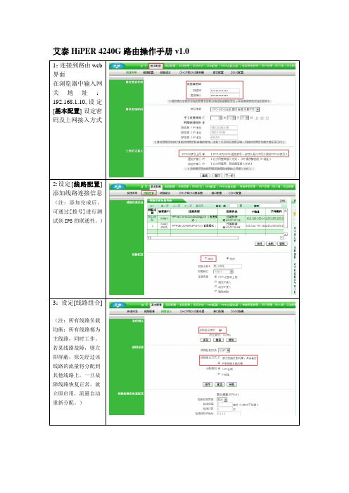
网段:192.168.1.0
掩码:255.255.255.0
(注:DNS为ISP联通DNS并启用DNS代理)
5:配置接口IP地址
6:启动PPPOE服务器。
(注:起始IP地址可以任意设定)
7:添加PPPOE客户端
上行带宽:512K
下行带宽:1.5M
艾泰HiPER4240G路由操作手册v1.0
1:连接到路由web界面
在浏览器中输入网关地址:192.168.1.10,设定[基本配置]-设定密码及上网接入成后,可通过[拨号]进行测试到IPS的联通性。)
3:设定[线路组合]
(注:所有线路负载均衡:所有线路都为主线路,同时工作。若某线路故障,则立即屏蔽,原先经过该线路的流量将分配到其他线路上。一旦故障线路恢复正常,就立即启用,流量自动重新分配。)
AgilentEB频谱解析总结计划仪使用说明

Agilent E4402BESA-E Series Spectrum Analyzer使用方法简介宁波之猫2009-6-17目录1简介Agilent ESA-E系列是能适应将来需要的Agilent中性能频谱剖析仪解决方案。
该系列在丈量速度、动向范围、精度和功率分辨能力上,都为近似价位的产品成立了性能标准。
它灵巧的平台设计使研发、制造和现场服务工程师能自定义产品,以知足特定测试要求,和在需要时用新的特征升级产品。
该产品采纳单键丈量解决方案,并拥有易于阅读的用户界面和高速丈量的性能,使工程师能把较少的时间用于测试,而把更多的时间用在元件和产品的设计、制作和查错上。
2.面板操作区1.察看角度键,用于调理显示,以适于使用者的察看角度。
2.Esc 键,能够撤消输入,停止打印。
3.无表记键,实现左侧屏幕上紧挨的右侧栏菜单的功能。
4. Frequency Channel (频次通道)、Span X Scale(扫宽 X 刻度)和 AmplitudeY scale(幅度 Y 刻度)三个键,能够激活主要的调理功能(频次、X 轴、 Y 轴)并在右侧栏显示相应的菜单。
5.Control (控制)功能区。
6.Measure(丈量)功能区。
7.System(系统)功能区。
8.Marker (标志)功能区。
9.软驱和耳机插孔。
10.步进键和旋钮,用于改变所选中有效功能的数值。
11.音量调理。
12.外接键盘插口。
13.探头电源,为高阻抗沟通探头或其余附件供给电源。
14.Return 键,用于返回先前选择过的一级菜单。
15.Amptd Ref Out ,可供给- 20dBm 的 50MHz 幅度参照信号。
16.Tab(制表)键,用于在界线编写器和修正编写器中四周挪动,也用于在有 File 菜单键所接见对话框的域中挪动。
17.信号输进口(50Ω)。
在使用中,接 50Ω BNC 电缆,探头上一定串连一隔直电容( 30PF 左右,陶瓷封装)。
艾泰科技产品线介绍

维护管理
• 用户状态统计 • 流量统计 • NAT会话统计 • 上网监控
安全管理
• 防攻击 • 防病毒 • 入侵监测 • 访问控制
UTT安全网关产品线产品
UTT 5830G
UTT 6830G
功
UTT 4840G
能
与
性
HiPER 4521
能
UTT 3640
UTT 2512
价格
艾泰科技产品特色
• 艾泰科技系列网关就是指集路由器、防火 墙、管理器、诊断仪功能为一体的网络产 品。
行为管理
• 流量控制 • 时间控制 • 业务管理 • 个性定制
维护管理
• 用户状态统计 • 流量统计 • NAT会话统计 • 上网监控
安全管理
• 防攻击 • 防病毒 • 入侵监测 • 访问控制
HiPER宽带网关产品线产品
HiPER 6530G
HiPER 4240G
HiPER 4210G
HiPER 3321NB HiPER 3311NB
服”免费体验。
智尊系列产品介绍
每秒转发 230K数据包
每秒转发 300K数据包
NE6000
功
每秒转发
能
190K数据包
与
性
能
每秒转发
NE2200
150K数据包
NE1200
NE4000
价格
智尊系列产品硬件参数
产品型号 CPU
FLASH 内存 大小 电源
防雷特性 WAN口 LAN口
NE1200
Intel IXP 533M 4M 32M
提供10M/100M LAN口(4个内置的交换式 以太网口)和1个UPLINK端口
Boonton 4240系列RF功率计说明书

Taking performance to a new peak4240 Series RF Power MeterThe 4240 series of CW RF power meters provides the high speed measurement capability needed in a production environment, as well as the simplicity of operation required for bench top use. It provides very accurate measurements from -70 dBm to +44 dBm (sensor dependent) and has a rapid display update rate for tuning applications. The easy to read LCD displays both chan-nels simultaneously with numeric and bar graph information.Five digit resolution, 90 dB dynamic rangeThe 4240 series has a 5 digit resolution and can display the value in either logarithmic or linear units. The 4242 two chan-nel model allows the simultaneous comparison of multiple in-puts during testing and in difference and ratio measurements.Sensor CompatibilityThe 4240 series is compatible with all Boonton CW diode, thermocouple, and waveguide sensors from 10 kHz to 40 GHz. Older sensors can be upgraded with a data adaptor to use the convenient auto calibration feature on the meter eliminating the need for manual calibration data input. Standard IEEE-488 GPIB and RS232 ports allow convenient interface with an ATE system. The SCPI command set, or an available LabVIEW driver allow simple integration with your existing ATE system. The 4240 Series is capable of HP437, HP438, 4220A and 4230A emulation modes for additional compatibility in any ATE system.Features• -70 dBm to +44 dBm, depending on sensor• 90 dB dynamic range, depending on sensor• 10 kHz to 40 GHz measurement range• Single or dual-channel display• >200 measurements per second• HP437, HP438, and Boonton 4220A/4230A emulation • Automatically loads sensor data• Simple software control via SCPI language• 50 MHz step calibrator• IEEE-488 and RS-232 interfaces standardInput Power (dBm)10001001010.1-70-55-40020ReadingsPerSecondFast-mode Throughput (60 Hz Operation)The 4240 Series offers a backlit LCD,which provides simultaneous readingsof one or both channels, displayedwith individually programmable unitsand resolution.The instrument can measure gainand output power, and performsum, difference, ratio and relativemeasurements. Selectable dual bargraphs assist with gain and peakingadjustments.Automatic step calibration “AutoCal”function uses built-in 50 MHz sweepcalibrator to offer best-in-class powerlinearity.2SpecificationsFrequency Range 10 kHz to 40 GHzSensor dependentPower Range -70 dBm to +44 dBmSensor dependentNumber of Channels One or twoMeasurement Speed 1 channel: 200 readings/sec2 channels: 100 readings/sec Power SensorsAccepts sensor data adapter with full-calibration data, including high-frequency calibration factors, stored in nonvolatile memory. Sensor menu accesses sensors displaying sensor serial number. Com-patible with all Boonton CW power sensors. See Sensor Data Sheet. Dynamic RangeUp to 90 dB with diode sensors, 50 dB with thermocouple sensors See Power Sensor SpecificationsInputsFront panel sensor connectors standard, rear panel inputs optional OutputsFront panel CALOUT connector, 0 dBm, 50 MHz, -60 to 20 dBmRear panel RECORDER BNC connector, 0 to 10 V into 1 MΩOutput impedance is 9.09 kΩ. May be operated into 1 kΩ for 1V fs Rear panel IEEE-488 and RS-232Emulation 4220A, 4230A & HP437, 438 DisplaysMenu-driven 20 character x 4 line LCD display. Simultaneous display of dual channels with bar graph proportional to data display. Display Units Absolute: watts or dBmRelative: dBrDisplay Resolution 5 digits; nW, µW, mW, and W0.001 dB, dBm, and dBr Calibration Factors+3.00 to -3.00 dB, stored in nonvolatile memory. Meter linearly inter-polates between entries as required.Zeroing/AutoCalAutomatic functions to calculate, store, and apply zero corrections and generate linearity calibration data for power sensors. Ranging Automatic or manualFiltering 0.05 to 20.00 seconds Display Offset -99.99 to 99.99 dB Calibration SourceOperating Modes Off, On CWFrequency 50.025 MHz ± 0.1%Level Range -60 to +20 dBm Resolution 0.1 dBRF Connector Type N (f)Source VSWR 1.05 (reflection coeff. = 0.024)UncertaintyTotal accuracy is the sum of the following uncertainties:(errors are ±worst case)Instrumentation Uncertainty 0.2% at full scaleCalibrator Uncertainty, 0C to 20C, NIST traceable0 dBm ±0.055 dB (1.27%)+20 to -39 dBm ±0.075 dB (1.74%)-40 to -60 dBm ±0.105 dB (2.45%)Other UncertaintiesFor sensor, noise, high-frequency calibration uncertainty, consult power sensor specifications.Other SpecificationsPower Consumption 85-260 VAC, 47 to 63 Hz85-135 VAC, 47 to 400 Hz15 Watts, 25 VAOperating Temperature 0° to +55 °CWeight 5 lbs (2.3 kg)Dimensions 8.26” (21.0 cm) wide3.48” (8.9 cm) high13.5” (34.3 cm) deepIEEE-488 Interface Complies with IEEE-488 andimplements SH1, AH1, T6, L4,SR1, RL1, DC1, and DT1RS-232 Interface Complies with RS-232(9-pin D-sub connector)3Wireless Telecom Group Inc. 25 Eastmans Rd Parsippany, NJ United States Tel: +1 973 386 9696 Fax: +1 973 386 9191 © Copyright 2013 All rights reserved.B/4240/0913/ENNote: Specifications, terms and conditions are subject to change without prior notice.Ordering Information4241 Single Channel 4242 Dual Channel -01 Rear sensor inputs-02 Calibrator, rear panel output -30Warranty extended to 3 yearsAccessories RequiredOne or more of the available power sensors.NOTE: 5ft. sensor cable and data adapter included with instrument based on number of channels ordered.Accessories Available41-2A/10Sensor/Probe Interconnecting Cable (10 ft). A special low-noise cable that connects the power sensor to the power meter. 41-2A/20 Sensor/Probe Interconnecting Cable (20 ft)41-2A/50 Sensor/Probe Interconnecting Cable (50 ft)41-2A/100 Sensor/Probe Interconnecting Cable (100 ft)95004701A F/F Adapter, 41-2A 95004901A Bulkhead Connector F/F 95403001A Rack Mounting Kit, 4240 Series 95109001A Sensor Data Adapter95006201A Transit caseHolds the 4240 series & up to 4 sensorsPower SensorsWide Dynamic Range Diode SensorsModel Number Frequency Range Power (dBm)51071A 10 MHz to 26.5 GHz -70 to +20 51072A 30 MHz to 40.0 GHz -70 to +20 51075A 500 kHz to 18.0 GHz -70 to +20 51077A 500 kHz to 18.0 GHz -60 to +30 51079A 500 kHz to 18.0 GHz-50 to +40Thermocouple SensorsModel Number Frequency Range Power (dBm)51100(9E) 10 MHz to 18.0 GHz -20 to +205120010 MHz to 18.0 GHz0 to +37Special Purpose SensorsModel Number Frequency Range Power (dBm)51011 (EMC) 10 kHz to 8.0 GHz -60 to +20 51011 (4B) 100 kHz to 12.4 GHz -60 to +2051013 (4E) 100 kHz to 18.0 GHz -60 to +2051015 (5E) 100 kHz to 18.0 GHz -50 to +3051033 (6E) 100 kHz to 18.0 GHz -40 to +33 51078100 kHz to 18.0 GHz-20 to +37Diode Average SensorsModel Number Frequency Range Power (dBm)51085500 kHz to 18 GHz-30 to +20。
艾泰4240g配置分析

HiPER 4240G路由配置分析1. 选择安装地点在安装前需选择一个适当的地方安装HiPER 4240G,确保其电源是关闭的。
HiPER 4240G是按照19英寸标准机架的尺寸进行设计的,一般可以将其安装到机架上,也可将其安装在工作台上。
1) 安装到机架将HiPER 4240G安装到19英寸标准机架上,如图2-23所示,可根据机架的情况使用随机附带的固定附件进行安装。
2) 安装到工作台若没有19英寸标准机架,可直接将设备放置在干净的工作台上。
注意:请保证工作台的平稳性和良好接地,同时不要在设备上面放置重物。
2. 连接HiPER 4240G到管理计算机或局域网使用标准的网线连接管理计算机到HiPER 4240G的局域网(LAN)口,或者连接交换机到LAN口,如图2-24所示。
设备将会自动适应10M 、100M或1000M的设备。
3. 连接HiPER 4240G到Internet使用Cable/DSL Modem厂商提供的网线将Cable/DSL Modem连接到HiPER 4240G的广域网口,如图2-24所示。
如果没有厂商提供的网线,请使用标准网线。
4. 打开电源将随机配置的电源线连接到HiPER 4240G 的电源接口(位于后面板),并将设备的电源开关(位于后面板)打开。
注意!连接电源之前确保电源供电、连接、接地正常,否则可能造成系统工作异常或系统损坏。
5. 检查系统指示灯系统指示灯位于前面板左边,分为2 组:第一组是左边的2 行2 列,共4 个,具体状态如;第二组是右边的2 行9 列,共18 个,1-5 对应LAN 口的五个交换口,6 对应WAN1 口,7 对应WAN2 口,8 对应WAN3 口,9 对应WAN4 口。
将随机配置的电源线连接到HiPER 4240G 的电源接口(位于后面板),并将设备的电源开关(位于后面板)打开。
注意!连接电源之前确保电源供电、连接、接地正常,否则可能造成系统工作异常或系统损坏。
MRF24J40MA 70329b_cn
MRF24J40MA数据手册2.4 GHz IEEE标准802.15.4™RF收发器模块 2008 Microchip Technology Inc.DS70329B_CNDS70329B_CN 第ii 页 2008 Microchip Technology Inc.提供本文档的中文版本仅为了便于理解。
请勿忽视文档中包含的英文部分,因为其中提供了有关Microchip 产品性能和使用情况的有用信息。
Microchip Technology Inc.及其分公司和相关公司、各级主管与员工及事务代理机构对译文中可能存在的任何差错不承担任何责任。
建议参考Microchip Technology Inc.的英文原版文档。
本出版物中所述的器件应用信息及其他类似内容仅为您提供便利,它们可能由更新之信息所替代。
确保应用符合技术规范,是您自身应负的责任。
Microchip 对这些信息不作任何明示或暗示、书面或口头、法定或其他形式的声明或担保,包括但不限于针对其使用情况、质量、性能、适销性或特定用途的适用性的声明或担保。
Microchip 对因这些信息及使用这些信息而引起的后果不承担任何责任。
如果将Microchip 器件用于生命维持和/或生命安全应用,一切风险由买方自负。
买方同意在由此引发任何一切伤害、索赔、诉讼或费用时,会维护和保障Microchip 免于承担法律责任,并加以赔偿。
在Microchip 知识产权保护下,不得暗中或以其他方式转让任何许可证。
商标Microchip 的名称和徽标组合、Microchip 徽标、Accuron 、dsPIC 、K EE L OQ 、K EE L OQ 徽标、MPLAB 、PIC 、PICmicro 、PICSTART 、rfPIC 、SmartShun 和 UNI/O 均为Microchip Technology Inc .在美国和其他国家或地区的注册商标。
FilterLab 、Linear Active Thermistor 、MXDEV 、MXLAB 、SEEVAL 、SmartSensor 和The Embedded Control Solutions Company 均为Microchip Technology Inc .在美国的注册商标。
- 1、下载文档前请自行甄别文档内容的完整性,平台不提供额外的编辑、内容补充、找答案等附加服务。
- 2、"仅部分预览"的文档,不可在线预览部分如存在完整性等问题,可反馈申请退款(可完整预览的文档不适用该条件!)。
- 3、如文档侵犯您的权益,请联系客服反馈,我们会尽快为您处理(人工客服工作时间:9:00-18:30)。
HiPER 4240G路由配置分析
1. 选择安装地点
在安装前需选择一个适当的地方安装HiPER 4240G,确保其电源是关闭的。
HiPER 4240G是按照19英寸标准机架的尺寸进行设计的,一般可以将其安装到机架上,也可将其安装在工作台上。
1) 安装到机架
将HiPER 4240G安装到19英寸标准机架上,如图2-23所示,可根据机架的情况使用随机附带的固定附件进行安装。
2) 安装到工作台
若没有19英寸标准机架,可直接将设备放置在干净的工作台上。
注意:请保证工作台的平稳性和良好接地,同时不要在设备上面放置重物。
2. 连接HiPER 4240G到管理计算机或局域网
使用标准的网线连接管理计算机到HiPER 4240G的局域网(LAN)口,或者连接交换机到LAN口,如图2-24所示。
设备将会自动适应10M 、100M或1000M的设备。
3. 连接HiPER 4240G到Internet
使用Cable/DSL Modem厂商提供的网线将Cable/DSL Modem连接到HiPER 4240G的广域网口,如图2-24所示。
如果没有厂商提供的网线,请使用标准网线。
4. 打开电源
将随机配置的电源线连接到HiPER 4240G 的电源接口(位于后面板),并将设备的电源开关(位于后面板)打开。
注意!连接电源之前确保电源供电、连接、接地正常,否则可能造成系统工作异常或系统损坏。
5. 检查系统指示灯
系统指示灯位于前面板左边,分为2 组:第一组是左边的2 行2 列,共4 个,具体状态如;第二组是右边的2 行9 列,共18 个,1-5 对应LAN 口的五个交换口,6 对应WAN1 口,7 对应WAN2 口,8 对应WAN3 口,9 对应WAN4 口。
将随机配置的电源线连接到HiPER 4240G 的电源接口(位于后面板),并将设备的电源开关(位于后面板)打开。
注意!连接电源之前确保电源供电、连接、接地正常,否则可能造成系统工作异常或系统损坏。
HiPER 4240G配置步骤
1.连接路由
在IE输入192.168.1.1进入路由器,弹出下对话框输入用户名及密码登陆。
2.快速向导
在WEB页面顶端单击“快速向导”超链接,进入“快速向导”设置界面。
快速向导提供配置设备的最基本功能,如配置线路上网等。
如下图所示:
单击“退出向导”按钮,即可退出快速向导配置,返回到系统信息页面;
单击“下一步”按钮,即可进入快速向导的第一页LAN口地址设置页面。
LAN口地址配置
快速向导的第一个页面可对设备的LAN地址进行设置,如下图所示:
IP地址:设备LAN口的IP地址,默认为192.168.1.1;子网掩码:设备LAN口的子网掩码,默认为255.255.255.0;
单击“上一步”按钮,即可返回到快速向导介绍页面;
单击“下一步”按钮,即可进入快速向导的第二页上网接入方式设置页面。
我公司是网通固定ip
默认线路WAN1口IP设置为下
Ip: 218.29138.142
子网掩码:255.255.255.248
网关: 218.29.138.137
线路配置
如果公司有需求可以增加一个备用光纤用在wan2口,通过路由进行网络负载均衡辅助功能,现在我们用的只用网通默认线路,如下图。
线路组合功能
由于现行只有网通默认一条光纤进行局域网的办公使用,此功能无法得到应用,此功能可实现网络负载均衡。
DHCP和DNS服务器
启用 DHCP 服务器功能后,设备就能够为局域网计算机动态分配 IP 地址、子网掩码、网关、以及 DNS 服务器、 WINS 服务器等信息。
启用 DNS 代理功能后,局域网的计算机只需将 DNS 服务器设置为设备的 LAN 口地址,就可以正常使用 DNS 服务。
至少必须正确配置“主 DNS 服务器”, DNS 代理才能正常
工作。
若 DHCP 服务器功能和 DNS 代理功能同时启用,设备给局域网中计算机分配的主 DNS 服务器的 IP 地址就是设备的 LAN 口地址。
使用 DHCP 服务为局域网中的计算机自动配置 TCP/IP 属性是非常方便的,但是会造
成一台计算机不同时间被分配到不同 IP 地址的现象。
为了方便控制对局域网中计算机的IP 地址的分配,可使用 DHCP 手工绑定功能,将计算机的 MAC 地址与某个 IP 地址绑定,从而为局域网中指定的 MAC 地址固定分配预设的 IP 地址。
Ip地址规划办法
对局域网IP进行统一mac地址绑定,进行固定地址的划分以办公区域为单位分网段管理。
如下图进行地址添加录入,以及对ip进行固定管理。
用户管理:此功能可看出各ip活动的时间,及接受发送数据包情况,使用率不嫩超过10%,如超过应及时对其用户终止上网。
. 系统管理-软件升级
对路由器系统进行升级操作,最新版本2011.7.7日现版本为2008版。
配置管理:可以对系统的配置信息进行导出,以及对现有系统进行导出保存,有助系统的恢复操作。
远程管理:管理员可以通过其他网络进行内网路由的管理,连接方式为http,snmp软件telnet命令来实施。
Vpn网络通道:
公司与各驻地公司之间可以通过路由器进行通道间的网络单隧道通讯。
用户的管理:带宽控制可以使用全局策略进行统一配置各用户的使用带宽。
也可以通过个性化管理进行逐一的配置。
组管理:可以对一个网段的用户建立一个组进行策略的实施,并根据管理要求进行策略实施。
防火墙配置:
通过对策略的编制对ftp、web、https、pop3、dns、epmap等访问方式的控制。
安全配置:
可以通过导入的方式进行策略库的导入,艾泰提供最新的策略控制方案,也可以对现有的策略进行更新。
Mac重复信息:
启用Arp更新限制,可以避免用户不能上网的情况,特别是由动态分配更改为固定ip的时候,路由设备收不到用户的arp广播,mac分配的是动态的形式,而更改后的ip与局域网内部影响通讯,但对网通讯则因为arp受骗产生错误。
实现内网两个网段且不可互访
配置方法:
一、在“基本配置—接口配置”IP地址1和IP地址2分别设置为192.168.1.1,子网掩码255.255.255.0,192.168.2.1 子网掩码:255.255.255.0 如下图所示:
这样配置之后,内网192.168.1.0/24 网段的地址网关指向192.168.1.1,192.168.2.0/24网段的地址网关指向192.168.2.1就可以上网的。
默认情况下这两个网段是可以互访的;
二、为了禁止他们互访我们可以做防火墙策略禁止他们互相访问
1、打开“防火墙—地址组”分别建立两个地址组如下图:
2、到“防火墙—访问控制策略”这个页面设置访问控制策略禁止1.0段访问2.0这个段;如下图:
3、策略做完之后在全局配置,启用访问控制策略并保存
至此1.0网段和2.0网段是不可以互相访问的。
三、最后为了保证内网pc不可以随意更改IP地址来访问对方网段。
我们可以在“高级配置—IP/MAC绑定”界面对内网用户都进行IP/MAC绑定,并且把“允许未被IP/MAC绑定的主机通过”这个勾去掉。
这样就实现了用户的所有需求。
