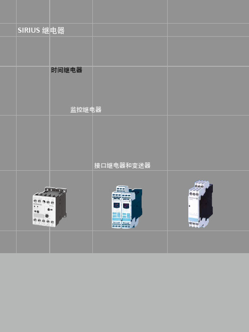
西门子SIRIUS继电器-时间继电器
西门子SIRIUS继电器接口继电器和变送器

mA 动作次数 动作次数
1 V AC/DC,0.1 20 x 106 1 x 10⁵
动作频率
动作次数 5000
/ 小时
触头材料, 3TX7 00.-...02
Ag/Ni 0.15 硬金镀层
硬金镀层功率限值,3TX7 00.-...02
• 电压
V
30
• 电流
mA
20
注:如果连接感性负载,可延长接口继电器的使用寿命。 1)容性负载会导致触头出现微小熔焊。
11/5
SIRIUS
3TX70 接口继电器
插针式 / 非插针式接口继电器
技术参数(续)
型号 通用数据
额定绝缘电压 Ui(污染等级 3) 继电耦合器安装隔离 线圈和触头之间,符合标准 EN 60947-1,附录N
防护等级
短路保护,符合标准 IEC 60947-5-1 (防熔焊电流Ik ≥ 1 kA) 熔丝, gL/gG 工作等级 允许环境温度
0.7 ... 1.25 x Us 0.8 ... 1.1 x Us 0.5 W;3TX7 00.-...05:1 W,230 V DC/6 VA 或 230 V AC 时
动作时间,Us 时
- 宽 6.2
mm
- Us = 24 V
mA
- Us > 24 V
mA
- 宽 12.5 mm 以上
mA
例外:3TX7 00 .-1BF05 mA mA
连接端子 外壳
工作
3TX7 004/3TX7 005
V
300
V
至 300 AC
IP20
IP30
A
4
ºC -25 ... +60
继
西门子(SIEMENS)3RP系列电子式时间继电器
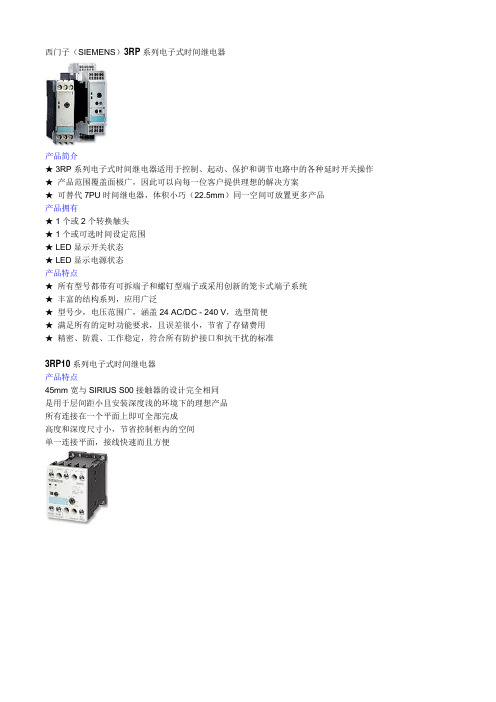
西门子(SIEMENS)3RP系列电子式时间继电器
产品简介
★ 3RP系列电子式时间继电器适用于控制、起动、保护和调节电路中的各种延时开关操作★产品范围覆盖面极广,因此可以向每一位客户提供理想的解决方案
★可替代7PU时间继电器,体积小巧(22.5mm)同一空间可放置更多产品
产品拥有
★ 1个或2个转换触头
★ 1个或可选时间设定范围
★ LED显示开关状态
★ LED显示电源状态
产品特点
★所有型号都带有可拆端子和螺钉型端子或采用创新的笼卡式端子系统
★丰富的结构系列,应用广泛
★型号少,电压范围广,涵盖24 AC/DC - 240 V,选型简便
★满足所有的定时功能要求,且误差很小,节省了存储费用
★精密、防震、工作稳定,符合所有防护接口和抗干扰的标准
3RP10系列电子式时间继电器
产品特点
45mm宽与SIRIUS S00接触器的设计完全相同
是用于层间距小且安装深度浅的环境下的理想产品
所有连接在一个平面上即可全部完成
高度和深度尺寸小,节省控制柜内的空间
单一连接平面,接线快速而且方便。
西门子sirius软起动器

SIRIUS 软起动器:出色地保护电机和机械设备,减轻电网压力宣传手册• 2010SIRIUSAnswers for industry.SIRIUS — 适合各种应用的理想软起动器目前,三相电机通常作为用户最终选择的驱动形式。
但在很多情况下,直接起动或星三角起动等传统起动方式会引起机械冲击、电网电压骤降等问题。
为此,西门子公司推出了全系列的软起动解决方案,即 SIRIUS 软起动器,包括标准型和高性能型,可适用于任何应用场合。
SIRIUS 软起动器能够平稳起动/停止三相电机,轻松、高效的实现前瞻性的最佳设备解决方案。
2三相电机的软起动SIRIUS 软起动器—优点一览• 软起动,软停车• 平滑起动• 降低电机起动时的峰值电流• 避免起动过程中引起电网电压波动• 减轻电网压力• 减轻传动系统中的机械冲击• 与其它起动器相比,显著节省空间和布线• 降低维护费用• 操作简便• 可与其它 SIRIUS 设备完美搭配软起动器的工作原理软起动器通过限制起动电流和起动转矩,能够可靠地防止起动过程中的机械冲击和电网压降。
通过对可控硅导通角的控制,来降低电机起动电压,并在设定的起动时间内,将电机起动电压升高到额定电压。
凭借这种电机电压的无阶跃控制,可以根据被驱机器的负载特性对电机进行调节,平缓加速机械设备,从而显著提高机械设备的运行性能,延长其使用寿命。
总之:通过软起动/软停车,能够有效保护所连设备,确保生产运行平稳、可靠。
可以与负载馈电器配合使用吗?当然可以。
结合断路器,例如 SIRUIS 3RV,可以很容易地组成小型非熔断器保护的负载馈电装置。
不仅如此,由于该产品集成了过载保护功能,用户还可快速实现节省空间的带熔断器保护的负载馈电装置1)。
如何进行连接?连接方式与其它 SIRIUS 设备完全相同:使用螺钉型接线端子或弹簧型接线端子。
根据需要,也可使用其它连接方式。
能否进行通讯?当然。
西门子软起动器具有通讯功能。
西门子SIRIUS继电器-监控继电器

SIRIUS继电器时间继电器监控继电器接口继电器和变送器SIRIUS 继电器10/104SIRIUS继电器3UG4 监控继电器3UG4三相电压监控继电器•电压范围宽,它可以应用于从160V到690V的所有电源电压而无需辅助电压•可以灵活地设置成高范围、低范围或窗口控制•延时时间可调,手动/自动复位可选•所有型号的宽度均为 22.5mm,节省柜内空间•对于数字型监控继电器,可永久显示实际值和故障类型•所有型号都配有可拆卸端子•所有型号都可选用螺丝型端子或笼卡型端子新型3UG4监控继电器通过监控三相电压、单相电压和单相电流使电源、设备和系统获得最大程度的保护。
这意味着电源、电压和电流故障可以被及早检测出来,避免造成更大的损失。
断相熔断器熔断控制电源故障低电压电机电流增大,导致过热某设备意外复位电流监控过载监测在额定转矩附近进行欠载监测对电子负载的功能性进行监控断线监控能量管理(相电流监控)10/210/3SIRIUS继电器3UG4 监控继电器3UG4 三相电压监控继电器螺钉型螺子�笼卡型端子�12☐☐10/4SIRIUS继电器3UG4 监控继电器3UG4 三相电压监控继电器10/5SIRIUS 继电器3UG4 监控继电器3UG4 三相电压监控继电器10/610/7SIRIUS 继电器3UG4 监控继电器3UG4 三相电压监控继电器3UG45 11 监测继电器功能3UG45 11可监测三相电源的相序,而且可用于监测断相,但存在无法可靠检测由感性负载形成感应电压情况下断相的可能性。
时序图如下:3UG45 12 监测继电器功能3UG45 12 可监测三相电源的相序、断相及 10% 的相不平衡。
时序图如下:3UG45 13 监测继电器功能3UG45 13可监测三相电源的相序、断相、20%的相不平衡及低电压。
断电延时为 0.1~20s 可调。
电压迟滞为5% 。
时序图如下:SIRIUS继电器3UG4 监控继电器3UG4 三相电压监控继电器平衡及低电压。
西门子开关与保护设备-过载继电器
- -
- - 3RU51 46-4JB1 3RU51 46-4KB1
3RU51 46-4LB1 3RU51 46-4MB1
4) 最大的熔断器规格。
4/4
开
关
SIRIUS(国产)3RU6 / 3RU5 热过载继电器
与 保
护
3RU5 热过载继电器
设
备
选型和订货信息
螺钉接线端子,与接触器插接 1)或独立安装,CLASS 10
功能和结构: • 过载和缺相保护 • 辅助触点 1 NO + 1 NC • 手动/自动复位
• 开关位置指示 • 测试功能 • 停止按钮
3RU61 16-0AB0 3RU61 16-0BB0 3RU61 16-0CB0 3RU61 16-0DB0
3RU61 16-0EB0 3RU61 16-0FB0 3RU61 16-0GB0 3RU61 16-0HB0
3RU61 16-0JB0 3RU61 16-0KB0 3RU61 16-1AB0 3RU61 16-1BB0
开关与保护设备
电动机保护断路器 接触器和接触器组合 中间继电器 过载继电器 软起动器
开关与保护设备
ห้องสมุดไป่ตู้
国产过载继电器
SIRIUS(国产)3RU6/3RU5 热过载继电器 4/2 介绍 4/3 通用数据 3RU6/3RU5 热过载继电器 4/4 选型和订货信息 3UA6 热过载继电器 4/6 选型和订货信息 4/7 附件 4/7 选型和订货信息
至 +80 ºC 的温度范围,上限设定值必须按下表中给定的修
正系数进行修正。
图:3RU61 26 热过载继电器
与接触器连接的插接件: 与接触器进行完美的电气和机械连接。通过这些插接件, 过载继电器可以直接与接触器进行插接。也可选择独立安 装支座实现独立安装。
西门子SIRIUS安全产品系列说明书

Which sensors can be connected?SIRIUS ACT EMERGENCY STOP 3SU18command devicesSIRIUS 3SE29/39 foot switchesSIRIUS ACT 3SU1 two-hand operation consolesSIRIUS 3SE7cable-operated switchesSIRIUS 3SE5 position and safety switchesSIRIUS 3SE6 non-contact safety switchesIntegrated and efficientsafety chain2SIRIUS 3RT contactorsSIRIUS 3RA6 compact startersSIRIUS 3RM1 motor startersFrom detecting to evaluating and reacting.Sensors and actuators work together perfectly to create the ideal conditions for complete safety chains with SIRIUS Safety. These chains are not only extremely reliable but are also much quicker and easier to set up.An important element are the position and safety switches.P r o t e c t iv ed o o rE m e r g e n c ys t o pL i g h t a r r a yL a s e r s c a n n e rM a tT w o -h a n dc o n t r o lpa n e lT i m e -d e l a y e ds h u t d o wn P r o t e c t i v e d o o rw i t hl o c k i n gd e v i c eI n d e p e n d e n to u t p u tf u n c t i o nsM u t i n g1234EN 50 047Main advantages at a glance• Reduced variance and stock-keeping costs due to modular design• Plug-in design and a standardized interface simplify replacement and installation of the actuator heads • All actuator heads can be rotated in 22.5° increments • Quick-connect technology for plastic enclosures (31 mm) reduces mounting times by up to 25%• Choice of connectors and rollers• The entire ASIsafe electronics is integrated in a standard enclosure• LED displays optionally available for all enclosures • Higher degree of safety with redundant shutdown and additional signaling for versions with 3-pole contact blocks (enclosure dimensions as for 2-pole contact blocks)• Versions with increased corrosionprotection and for use down to –40°CSIRIUS position switches4Complete unitsPlastic or metal enclosure 31 mm wide, according to EN 50 047, with snap-action contacts 1 NO / 1NCRounded plunger, high-grade steel––Roller plunger X–Roller lever–X 3SE5122-0CH01Twist lever–X3SE5122-0CH50Twist lever, infinitely adjustable length–X= p ositive opening* – =withhigh-gradesteel roller** – =withplasticroller Our position switches can be ordered in a modular design or as complete units – already fitted with an actuator head. You will find further versions, such as compact switches, non-encapsulated designs or switches for ambient temperatures down to –40°C at: /sirius/configurators5Mechanical safety switcheswith separate actuatorsSafety switches with a separate actuator are used where the position of doors, covers or protective grilles must be monitored for safety reasons. 3SE5 safety switches with a separate actuator without a locking device have the same enclosures as the 3SE5 position switches (modular system). Safety switches with a locking device 3SE53 are special safety-related devices which prevent an unforeseen or intentional opening of protective doors, protective grilles or other covers for as long as a dangerous situation is present (i.e. follow-on motion of the switched-off machine).63SE5000-0AB01–––3SE5000-0AD053SE5000-0AC03–––3SE5000-0AE05––3SE5000-0AF05–3SE5000-0AR01––+3SE5000-0AH00++–3SE5000-0AA013SE5000-0AA02–3SE5000-0AA113SE5000-0AA12–3SE5000-0AA503SE5000-0AA51–3SE5000-0AA603SE5000-0AA613SE5000-0AA80––3SE5000-0AA82––= p ositive openingPlain plunger Rounded plunger Roller plunger Roller lever Angular roller lever Spring rod Twist actuatorAdjustable-lengthtwist lever7Plain plungerRounded plunger (with overtravel)Roller plunger (with overtravel)Roller leverAngular roller leverSpring rod Twist actuatorAdjustable-lengthtwist lever3SE5000-0AB01––3SE5000-0AC02––––3SE5000-0AD02–3SE5000-0AE013SE5000-0AE02–3SE5000-0AE033SE5000-0AE04–3SE5000-0AF013SE5000-0AF02–3SE5000-0AF033SE5000-0AF043SE5000-0AR01–– +3SE5000-0AH00++–3SE5000-0AA013SE5000-0AA02–3SE5000-0AA113SE5000-0AA12–3SE5000-0AA503SE5000-0AA51–3SE5000-0AA603SE5000-0AA613SE5000-0AA80––3SE5000-0AA82––= p ositive opening8Non-contact RFID safety switches: An RFID safety switch consists of a coded RFID switch with an 8-pole M12 3SE6315-0BB02-1AP0Individually coded, multiple teach-in capability3SE6315-0BB03-1AP0Individually coded, single teach-in3SE6310-0BC01StandardNon-contact RFID safety switches with tumbler, locking force 1150N: An RFID safety switch with tumbler 3SE6415-1BB02Closed-circuit principle, individually coded, multiple teach-in capability3SE6415-1AB01Open-circuit principle, family coded3SE6415-1AB02Open-circuit principle, individually coded, multiple teach-in capability3SE640-1AC01Standard*Connection cable for both types of safety switches available in 3, 5, 10 and 15 metersNon-contact safety switchesThe SIRIUS 3SE63 RFID safety switches without tumbler and magnetically-operated switches and the 3SE64 RFID safety switches with tumbler and magnetically-operated switches leave no room for tampering. They conform to market safety requirements with maximum tamper resistance according to ISO 14119 as well as safety requirements according to SIL 3 (IEC 62061/IEC 61508) or PL e (ISO 13849-1) for monitoring the positions of movable protective devices.In the case of protective door tumblers, 3SE64 RFID safety switches provide reliable protection against dangerous follow-on motion and are suitable for protecting both people and processes. The unique rotating shaft and hub operating principle makes it possible to pull the protective door shut (latch force can be set to 25 N or 50 N) to an almost backlash-free end posi-tion with a simultaneous tumbler that even serves as a door stop, eliminating the need for an additional door stop.Non-contact magnetically operated safety switch: A magnetically operated switch comprises a coded switching 3SE6604-2BA With cable 3 m, 2NC 3SE6604-2BA01With M8 plug, 4-pole, 2NC 3SE6604-2BA10With cable 10 m, 2NC 3SE6605-2BA With cable 3 m, 1NO +1NC 3SE6605-2BA01With M8 plug, 4-pole, 1NO +1NC 3SE6614-4CA01With M8 plug, 4-pole, 2NC, LED3SE6704-2BA For 3SE660* versions 3SE6714-2BA For 3SE661* versions 3SE6605-3BA With cable 3 m, 1NO +1NC 3SE6605-3BA05With cable 5 m, 1NO +1NC 3SE6605-3BA10With cable 10 m, 1NO +1NC3SE6616-3CA01With 8 mm latching connection, 6-pin connector, 1NO +1NC +1NC 1)3SE6617-3CA01With 8 mm latching connection, 6-pin connector,1NO +1NC +1NC 1)3SE6627-3CA04With cable 3 m, 2NC +1NC 1)3SE6704-3BA For 3SE660* versions 3SE6714-3CA For 3SE661*/3SE662* versions3SX5601-3GA05 5 m, M8 socket, 4-pole3SX5601-4GA055 m, socket 8 mm, latching connection 6-pole 1)Signaling contact9SIL 3/PL eSIL 3/PL eSIL 3/PL eSIL 3/PL eSIL 3/PL eSIL 3/PL eWith 2x switches(enabling individual switch combinations)Maximum safetySafety Integrity Level SIL (IEC 62061/ IEC 61508)/Performance-Level PL (ISO 13849-1)With 1x switchMonitoring of 1 NO contactMonitoring of 1 NO contactMonitoring of 1 NO contactMonitoring of 2 NO contacts or 1 NO and 1 NC contactMonitoring of 2 NO contacts or 1 NO and 1 NCcontact Monitoring of 2 NO contacts or 1 NO and 1 NC contact SIL 1/PL c SIL 1/PL c SIL 1/PL c SIL 1/PL c SIL 2/PL d SIL 2/PL d Design type112Mechanical position and safety switchesSIMATIC ET 200SPSIRIUS 3SK safety relaysSIMATIC controllerSafety switches with separateStandard/compact 3SE51/3SE52/3SE54 3SF1 AS-i variantTampering protection(Acc. to DIN EN ISO 14119, TÜV certificate)low,actuator head uncoded Positive opening operation as per IEC 60947-5-1, positive drive, necessary in safety applicationslow,shaft uncoded low,3D-coded actuator without tumbler 3SE51/3SE52 3SF1 AS-i variantSafety hinge 3SE51/3SE52 3SF1 AS-i variantDetectingEvaluatingApplication examplesWith the position and safety switches almost all requirements in the industry can be met.Various application examples e.g. forguard door monitoring can be found here:Position switch with twist lever:Detection of positions and end positions of moving machine and system parts, such as e.g. conveyor belts and assembly linesPivoting doors and flaps, with fixedpositive connection between switch and door hinge, switching angle 10°Roller door or position monitoring of grilles or doors/cs/ww/en/ps/16403/ae/et200sp/safety-relays /simatic-safety1.) Without tumbler2.) W ith lockingdeviceSIRIUS Position and Safety Switches10SIL 3/PL e SIL 3/PL e Monitoring of 1 NO contact Monitoring of 2 NO contacts or 1 NO and 1 NC contactMonitoring of 2 NO contacts or 1 NO and 1 NC contact Self-monitoring with 2 electronic 0SSD safety outputsSelf-monitoring with 2 electronic0SSD safety outputs SIL 1/PL c SIL 3/PL e SIL 3/PL eSIL 3/PL eSIL 2/PL d 2444 actuatorNon-contact safety switches low, 3D-coded actuatorlow, coded switching magnet low or high (to choose), coded RFID security switches low or high (to choose), coded RFID security switches Magnet safety switches 3SE66/3SE67with tumbler 3SE53 3SF1 AS-i variant RFID safety switches 3SE63RFID safety switches with tumbler 3SE64Additional interlocking requirement, e.g. in the working area of a robot system: Shutdown of machines requires closed safety doors with tumbler guarding Monitoring of maintenance flaps (hoods, doors, grilles), especially suitable for confined spaces Monitoring of swing doors, flaps, hoods, grilles, vibration-proof and robust IP69, large switching interval Interlocking requirement for rotating, laterally movable or removable safety guards IP69, with latching, optimized hygiene standard with simultaneous highest personnel and process protection Application manual SIRIUS Safety IntegratedDownload here11Technical information and support are available at/SIOSor in the Industry Online Support App.Available for Android and iOsr e l y generalf or m a nce which in case of ac t p ly ast her de v e lpmSecurity information/industrialsecurity.。
SIEMENS 3RP系列时间继电器
sSIRIUS 3R–为新时代设计的时间继电器的设计理念源自于适配模数化模块系统,目前已产品家族的开发。
其中新一代时间继电器的特点是:适应用不同的工业行业,安装、使用迅速,操作简单,可靠性极高。
极佳的操作性能使 SIRIUS 3R 时间继电器特别适合于工业应用领域。
P R O D U C TD E S I G N A W A R D3RP15 时间继电器标准型紧凑设计的 3RP15 安装宽度仅 22.5mm , 具有绝大多数功能,辅助触头,时间及电压范围为标准设计,多档设置范围。
3RP10 时间继电器3RP10 的设计主要为配合电动机馈电装置,可与 S00 尺寸的接触器完美搭接。
3RP10 提供“通电延时”与“多功能”二种型式,每种都有 2 个电压范围 24V AC/DC ,100 - 127V AC 及 24V AC/DC ,200- 240V AC 。
3RP10 多功能型时间继电器有 7 个功能,由可换的编码插件实现。
“通电延时”型时间继电器已将功能固化,无须编码插件。
SIRIUS 3R - 针对馈电装置而设3RP10 时间继电器及 3RH 中间继电器均只有 45mm 宽。
且高度与深度相同,接线端子也具有相同高度,S00 系列的尺寸一致性与其他时间继电器相比可减少安装深度,故可降低对柜子深度的要求。
产品设计大奖高质量,高性能——现代安装技术的概念安装可靠,全球适用根据 IEC 947,继电输出在 AC15/DC-13 使用类别下可靠性极高,即使用于通断接触器也能实现很高的电气寿命,3RP 时间继电器的工作温度范围高达: -25°C ~ +50°C,高温工作可靠性高,符合全球相关安装标准,3RP10 时间继电器已通过 UL 及 CSA 标准。
使用 SIRIUS 3RP ——安装及连线方便,灵活所有新一代 SIRIUS 3RP1时间继电器均可安装于35mm 标准导轨,当然,也可螺钉安装,3RP10 无须附件,3RP15 的螺钉固定脚作为选购件。
西门子Sirius模块系统说明书
SELECTION GUIDESIRIUS modular system /sirius-modular-systemEFFICIENTLY COMBINEDEverything for the control cabinet: SIRIUS modular system Advantages at a glance:Load feeders:easy to implement up to 250 kW/400 V from standard devices with motor starter protectors for motor protection, contactors, overload relays and monitoring relaysModular design:a host of combination optionsin standardized designVariants and sizes:seven compact sizesInstallation:quick and easy installation of feedersthanks to link modulesAccessories:low variance with uniform accessories Connection types:screw and spring-type terminals availableIE3/IE4 ready:familiar reliability even when changingover to IE3/IE4 motorsApplication monitoring:mountable monitoring relay for simple application monitoring beyond the motorPossible combinations depending on requirement: Load feeders:Direct start (p. 3 – 5)Motor starter protectorfor motor protection (S00 to S3)Link module (S00 to S3)Contactor (S00 to S3)Monitoring relays (up to S2)or overload relaysThermally delayed Electronic AnalogicallyadjustableDigitallyadjustableLoad feeders:Soft start, solid-state contactors (p. 6 – 7)Motor starter protectorfor motor protection (S00 to S3)Link module (S00 to S3)Solid-state contactors(S00 and S0)3RW30 or 3RW40soft startersFor frequently switching AC drives on and off,our motor starter protectors can also be combinedwith solid-state contactors or reversing contactorsand an overload relay.2Wiring kit for contactorsReversing contactor assembly S003RA2913-2AA13RA2913-2AA2S03RA2923-2AA13RA2923-2AA2 (main circuit only)S23RA2933-2AA13RA2933-2AA2 (main circuit only)S33RA2943-2AA13RA2943-2AA2 (main circuit only)Contactor assy. f. wye-delta start S003RA2913-2BB13RA2913-2BB2S03RA2923-2BB1 3RA2923-2BB2 (main circuit only)S23RA2933-2BB13RA2933-2BB2*S33RA2943-2BB13RA2943-2BB2*Wye-delta function module, plug-inComprising one basic module and two coupling modules, rated control supply voltage 24 ... 240 V AC/DC, time setting range 0.5 ... 60 s (10, 30, 60 s selectable)S00, S0, S2, S33RA2816-0EW2033RV motor starter protectors/circuit breakersSizeMountable accessories DesignScrew terminalsSpring-type terminalsS00, S0, S2, S3Transverse auxiliary switch 1CO 3RV2901-1D –1NO+1NC 3RV2901-1E 3RV2901-2E Lateral (left) auxiliary switch 1NO+1NC 3RV2901-1A 3RV2901-2A 2NO 3RV2901-1B 3RV2901-2B Signaling switch 1NO+1NC 3RV2921-1M 3RV2921-2M Shunt release 210 ... 240 V AC 3RV2902-1DP03RV2902-2DP024 V DC 3RV2902-1DB03RV2902-2DB0Undervoltage release230 V AC 3RV2902-1AP03RV2902-2AP024 V DC 3RV2902-1AB4–Door-coupling rotary op. mech. 130 mm shaftBlack 3RV2926-0B Red/yellow 3RV2926-0C S00, S0Molded-plas. encl. f. surf. mounting IP55, black 54 mm wide 3RV1923-1CA0072 mm wide 3RV1923-1DA00S282 mm wide 3RV1933-1DA00S00, S0Molded-plas. encl. f. surf. mounting IP55, EMERG. STOP54 mm wide 3RV1923-1FA0072 mm wide 3RV1923-1GA00S282 mm wide3RV1933-1GA00Coil terminal moduleSize S0 – S3Size S0Connection from below3RT2926-4RB113RT2926-4RB123RV29 infeed systemFor sizes S00 and S0, the simplest method is to connect the components via the associated SIRIUS 3RV29 infeed system in each case.3-phase busbar for two motor starter protectors size S00/S0 With infeed on the left (incl. 3RV2917-6A end cover) With infeed on the right (incl. 3RV2917-6A end cover) For system expansion (incl. 3RV2917-5BA00 expansion plug)3RV2917-1A 3RV2917-1E 3RV2917-4A Plug-in connectors for contact with motor starter protectors Size S00 Screw terminals Spring-type terminals Size S0 Screw terminalsSpring-type terminals3RV2917-5CA00 3RV2917-5AA00 3RV1927-5AA00 3RV2927-5AA00Contactor base for contactors size S00, S03RV2927-7AA00AccessoriesSurge suppressorsSize S00Plug-in Without LED Varistor 127 ... 240 V AC 3RT2916-1BD00With LED 3RT2916-1JL00Without LED RC element 127 ... 240 V AC 3RT2916-1CD00Without LEDSuppr. diode 24 V DC 3RT2916-1DG00Size S0Without LED Varistor 127 ... 240 V AC 3RT2926-1BD00With LED 3RT2926-1JL00Without LEDRC element 127 ... 240 V AC3RT2926-1CD00Without LED Diode assy. 24 V DC3RT2926-1ER00Size S2Without LED Varistor AC 127 ... 240 V 3RT2936-1BD00With LED 3RT2936-1JL00Without LED RC element 127 ... 240 V AC3RT2936-1CD00Size S3Without LEDVaristor 127 ... 240 V AC 3RT2936-1BD00With LED 3RT2936-1JL00Without LEDRC element 127 ... 240 V AC3RT2946-1CD00ContactorsAuxiliary switch blocks, on front S00, S0, S2, S3Screw terminalsSpring-type terminals1NC 3RH2911-1HA013RH2911-2HA011NO+1NC 3RH2911-1HA113RH2911-2HA112NO+2NC 3RH2911-1HA223RH2911-2HA221NO 3RH2911-1HA103RH2911-2HA102NO3RH2911-1HA203RH2911-2HA20* main circuit only, set of cables for auxiliary circuit1276Overload relays and monitoring relaysTerminal supports f. stand-alone inst.Screw terminalsSpring-type terminals S003RU2916-3AA013RU2916-3AC01S03RU2926-3AA013RU2926-3AC01S23RU2936-3AA01–S33RU2946-3AA01–124Load feeders for direct startLoad feeders start loads by a combination of protection and switching functions.A load feeder assembly consisting of motor starter protector, contactor, overload relay or monitoring relayoffers suitable combinations for every application.Mot. starter prot.ContactorsOverload relaysMonitoring relaysThree-phase motorSetting range CLASS 10Solenoid voltageAux. switchThermally delayed CLASS 10ElectronicCLASS 10E 2-phase Basic, analogically adjustable3-phase Standard, digitally adjustablePower [kW]Current [A][A]Setting range [A]Meas. range [A]Supply voltage 24 – 240 V AC/DCSize, width S00, 45 mm 0.090.320.22 – 0.320.120.50.35 – 0.50.180.630.45 – 0.630.2510.7 – 10.37 1.250.9 – 1.250.55 1.6 1.1 – 1.60.752 1.4 – 21.1 3.2 2.2 – 3.21.54 2.8 – 42.2 6.3 4.5 – 6.338 5.5 – 84107 – 105.512.59 – 12.57.51611 – 16Spring-type term. to 32 A:2Spring-type term.:2Spring-type term.:CSpring-type term.:ESpring-type term.:2Size, width S3, 70 mm205036 – 50306345 – 63377557 – 75458465 – 84459375 – 9345/5510080 – 100Spring-type term. in aux. circuit: 3Spring-type term.: D0Straight-through Screw terminals: W1transf. Spring-type term.: X1Spring-type term.: 3 Increased switching cap. 100 kA:2Mot. starterprot.Contactors Overload relays Monitoring relaysThree-phase motor Setting rangeCLASS 10Solenoid voltage Aux. switch Thermally delayedCLASS 10ElectronicCLASS 10E2-phase Basic,analogicallyadjustable3-phase Standard,digitally adjustablePower[kW]Current[A][A]Setting range[A]Meas. range[A]Supply voltage24 – 240 V AC/DCSpring-type term. to 32 A: 2Spring-type term.: 2Spring-type term.: C Spring-type term.: E Spring-type term.: 2Necessary accessories: link module from motor starter protector to contactorSize Screw terminals Spring-type terminals (only for S00 and S0)S00 up to max. 32 A AC/DC*13RA1921-1DA003RA2911-2AA00S0 up to max. 32 A AC*23RA2921-1AA003RA2921-2AA00S0 up to max. 32 A DC*23RA2921-1BA003RA2921-2AA00S2 up to max. 65 A AC/DC*33RA2931-1AA00–S3AC/DC*43RA1941-1AA00–5Load feeders: Soft starters, solid-state contactorsSoft starters for current-limiting and torque-lim. starts reduce wear on the mech. power-transm. elements of the machine, relieve load on the power supply systemand protect the line efficiently against high switch-on peak currents by means of reduced current consumption. Solid-state contactors are intended for frequently switching AC drives up to 7.5 kW on and off and for reversing up to 3.0 kW. The devices are constructed with complete insulation and can be mounted directly on motor starter protectors.Spring-type term. to 32 A: 2Mot. starterprot.3RW30 soft startersOper. voltage 3 x 200 – 480 V AC3RW40 soft startersOper. voltage 3 x 200 – 480 V ACSolid-state contactorsOper. voltage 48 – 480 V ACSolid-state reversingcontactorsOper. voltage 48 – 480 V AC Three-phase motor Setting rangeCLASS 10Starts/hnormalstartingRated operat.currentStarts/hnormalstartingRated operat.currentRated operat.currentRated operat.currentPower[kW]Current[A][A][A][A][A][A]110 – 230 V AC/DC: 1110 – 230 V AC/DC: 1110–230 V AC/DC, 50/60 Hz: 2110–230 V AC/DC, 50/60 Hz: 26Increased switching cap. 100 kA at 400 V:2110 – 230 V AC/DC:1110 – 230 V AC/DC:1Necessary accessories: link modules from motor starter protector to soft starter/solid-state deviceSize Screw terminals Spring-type terminals only for S00, S0 with soft starters S00*23RA2921-1BA003RA2911-2GA00S0 up to max. 32 A *23RA2921-1BA003RA2921-2GA00S2 up to max. 65 A *33RA2931-1AA00–S3*43RA1941-1AA00–Mot. starter prot.3RW30 soft starterswithout overload protection3RW40 soft starters with overload protectionThree-phase motorSetting range CLASS 10Rated operational current Power [kW]Current [A][A][A]48509222410030005 1013301760022220380 07222022h t t p ://w w w .s i e m e n s .c o m /i n d u s t r i a l s e c u r i t y。
西门子SIRIUS继电器-时间继电器
SIRIUS继电器9/102时间继电器SIRIUS 继电器监控继电器接口继电器和变送器SIRIUS 继电器9/2时间继电器3RP15/3RP20 时间继电器电子式 3RP1/3RP2 时间继电器可用于所有需要进行延时操作的起动、保护以及开环和闭环控制回路。
借助其业已验证的设计概念和紧凑的节约空间设计,成为所有工业领域中电气柜、面板和控制器厂家理想的定时设备选择。
通电延时:• 抑制噪声脉冲• 平稳起动电机,对线路电压冲击小断电延时:• 在断开控制电源后,仍能继续运行(风扇运转)• 电源故障时,可实现急停或将设备或系统置于一个特定的状态星/三角转换:• 为防止相间短路,电机需在50ms 内从星型电路转换到三角形电路• 所有型号都采用可拆卸端子• 所有型号都可选用螺钉型端子或笼卡式端子• 一套可选的标签用于标明多功能时间继电器所设定的功能• 7 种基本型号即能满足各种应用• 宽电压范围的多功能时间继电器,使用更为便利• 最佳的性价比• 强制断开,硬金镀层触点(可用于DIN EN 954 1 Category 2安全回路,并可和电子式控制系统配套使用)• 密封性外壳,可确保按设定参数运行SIRIUS 继电器9/3时间继电器3RP15/3RP20 时间继电器1)当设定“∞” 时,无延时功能,仅用于现场检测。
如:检测开关动作性能。
2)线圈电压工作范围 0.8 ~ 1.1 x U s 。
3)线圈电压工作范围 0.7 ~ 1.1 x U s 。
SIRIUS继电器9/4时间继电器3RP15/3RP20 时间继电器1)当设定“∞”时,无延时功能,仅用于现场检测。
如:检测开关动作性能。
2)线圈电压工作范围 0.7 ~ 1.25 x U s 。
3)线圈电压工作范围 0.85 ~ 1.1 x U s 。
4)线圈电压工作范围 0.8 ~ 1.1 x U s 。
SIRIUS 继电器9/5时间继电器3RP15/3RP20 时间继电器1)功能见 3RP1901-0 功能标牌套装。
西门子SIRIUS监控继电器

通用型SIRIUS 继电器2丰富的SIRIUS 继电器产品线:通用型继电器谈到控制器、负载馈电器和驱动器,每一位工程师都会想到要采用先进的技术。
而谈到继电器接口、控制继电器和监控继电器,又要另外花时间寻找供货商。
令人振奋的是,这一切已成为过去。
这是因为我们只需在同一个家族-SIRIUS -就可以得到所有这些产品:不但性价比高,而且选型简便。
源自西门子的SIRIUS 继电器系列,可满足所有有关电机启动方面的需要。
无论是时间继电器,还是监控继电器,无论是超薄型接口继电器、插入式继电器,还是小型接触器,我们都能提供通用型继电器来满足各种应用需求。
SIRIUS 继电器 — 完整的产品线满足各种应用需求。
主要特点:■ 适用于多种应用■ 用户界面友好■ 多功能性■ 性能充分考虑实际需求■ 极高的性价比完美的系统:无论是在生产环境、还是在输送系统中,无论是监控电机和设备,还是控制复杂的工厂或系统,SIRIUS 时间继电器、监控和接口继电器都能保证一切安全可靠运行。
43RP15/3RP20时间继电器导轨安装电子式3RP1/3RP2时间继电器可用于所有需要进行延时操作的启动、保护以及开环和闭环控制回路。
借助其业已验证的设计概念和紧凑的节约空间设计,成为所有工业领域中电气柜、面板和控制器厂家理想的定时设备选择。
应用:通电延时:■ 抑制噪声脉冲。
■ 平稳启动电机,对线路电压冲击小。
断电延时:■ 在断开控制电源后,仍能继续运行(风扇运转)。
■ 电源故障时,可实现急停或将设备或系统置于一个特定的状态。
星/三角转换:■ 为防止相间短路,电机需在50ms 内从星型电路转换到三角形电路。
优点:■ 所有型号都采用可拆卸端子。
■ 所有型号都可选用螺钉型端子或笼卡式端子。
■ 一套可选的标签用于标明多功能时间继电器所设定的功能。
■ 7种基本型号即能满足各种应用。
■ 宽电压范围的多功能时间继电器,使用更为便利。
■ 最佳的性价比。
■ 强制断开,硬金镀层触点(可用于DIN EN954 1 Category 2安全回路,并可和电子式控制系统配套使用)。
西门子(Siemens) sirius技术支持指南说明书

Customer Self Repair (CSR)Maintenance and Service GuideFirst Edition /September 2021COPYRIGHT INFORMATIONNo part of this manual, including the products and software described in it, may be reproduced,transmitted, transcribed, stored in a retrieval system, or translated into any language in any form or by any means, except documentation kept by the purchaser for backup purposes, without the express written permission of ASUSTeK COMPUTER INC.(“ASUS”).ASUS PROVIDES THIS MANUAL “AS IS” WITHOUT WARRANTY OF ANY KIND, EITHER EXPRESS OR IMPLIED,INCLUDING BUT NOT LIMITED TO THE IMPLIED WARRANTIES OR CONDITIONS OF MERCHANTABILITY OR FITNESS FOR A PARTICULAR PURPOSE. IN NO EVENT SHALL ASUS, ITS DIRECTORS, OFFICERS, EMPLOYEES OR AGENTS BE LIABLE FOR ANY INDIRECT, SPECIAL, INCIDENTAL, OR CONSEQUENTIAL DAMAGES(INCLUDING DAMAGES FOR LOSS OF PROFITS, LOSS OF BUSINESS, LOSS OF USE OR DATA, INTERRUPTION OF BUSINESS AND THE LIKE), EVEN IF ASUS HAS BEEN ADVISED OF THE POSSIBILITY OF SUCH DAMAGES ARISING FROM ANY DEFECT OR ERROR IN THIS MANUAL OR PRODUCT.Products and corporate names appearing in this manual may or may not be registered trademarks or copyrights of their respective companies, and are used only for identification or explanation and to the owners’ benefit, without intent to infringe.SPECIFICATIONS AND INFORMATION CONTAINED IN THIS MANUAL ARE FURNISHED FOR INFORMATIONAL USE ONLY, AND ARE SUBJECT TO CHANGE AT ANY TIME WITHOUT NOTICE, AND SHOULD NOT BE CONSTRUED AS A COMMITMENT BY ASUS. ASUS ASSUMES NO RESPONSIBILITY OR LIABILITY FOR ANY ERRORS OR INACCURACIES THAT MAY APPEAR IN THIS MANUAL, INCLUDING THE PRODUCTS AND SOFTWARE DESCRIBED IN IT.Copyright © 2020 ASUSTeK COMPUTER INC. All Rights Reserved.LIMITATION OF LIABILITYCircumstances may arise where because of a default on ASUS’ part or other liability, you are entitled to recover damages from ASUS. In each such instance, regardless of the basis on which you are entitled to claim damages from ASUS, ASUS is liable for no more than damages for bodily injury (including death) and damage to real property and tangible personal property; or any other actual and direct damages resulted from omission or failure of performing legal duties under this Warranty Statement, up to the listed contract price of each product.ASUS will only be responsible for or indemnify you for loss, damages or claims based in contract, tort or infringement under this Warranty Statement.This limit also applies to ASUS’ suppliers and its reseller. It is the maximum for which ASUS, its suppliers, and your reseller are collectively responsible.UNDER NO CIRCUMSTANCES IS ASUS LIABLE FOR ANY OF THE FOLLOWING: (1) THIRD-PARTY CLAIMS AGAINST YOU FOR DAMAGES; (2) LOSS OF, OR DAMAGE TO, YOUR RECORDS OR DATA; OR (3) SPECIAL, INCIDENTAL, OR INDIRECT DAMAGES OR FOR ANY ECONOMIC CONSEQUENTIAL DAMAGES (INCLUDING LOST PROFITS OR SAVINGS), EVEN IF ASUS, ITS SUPPLIERS OR YOUR RESELLER IS INFORMED OF THEIR POSSIBILITY.SERVICE AND SUPPORTVisit our multi-language website at:https:///support/Table of Contents Disclaimer (4)Safety precautions (4)Installation tools (5)Before disassembly (5)Removing the base cover (6)Installing a RAM module (9)Installing an M.2card(SSD) (14)DisclaimerASUS is not responsible for direct, indirect, intentional or unintentional damages resulting from improper installation and operation.Safety precautions•Keep liquids or moisture away from your Notebook PC before installing or removing any components.•Place your Notebook PC on a stable surface before installing or removing any components. •Detach the clip or flap before removing the signal cables to prevent damage.•Disconnect the power plug by pulling the plug evenly to avoid damage. Ensure to connect the signal cables in the correct orientation.•Disconnect all power cables and remove the battery pack (if applicable) before cleaning your Notebook PC with liquid detergent to avoid risk of electric shock.•Disconnect all power cables and remove the battery pack (if applicable) before installing or removing any components. Be sure to thoroughly to read and follow the instructions in the manual.•To avoid Electrostatic Discharge (ESD) damage the electric components inside your computer, before handling components, use a grounded wrist strap or touch a safely grounded object to prevent electric products damaged by the electrostatic discharge.Please refer to Electrostatic Discharge (ESD) Protection Notes.•Keep liquids or moisture away from your Notebook PC to avoid short circuiting.•Hold components by the edges to avoid touching the Integrated Circuits (ICs).•Before re-connecting the AC power, ensure all components are properly installed.•Reduce the risk of fire or explosion by avoiding incompatible power adapters or batteries. Use only certified power adapters or batteries supplied by ASUS or authorized retailers.•Ensure the correct screw models are re-installed to your Notebook PC to prevent damage. Protection of Stored DataFor Your important data, please make periodic back-up copies of all the data stored on the hard disk or other storage devices as a precaution against possible failures, alteration, or loss of the data. ASUS AND ITS AFFILIATES WILL NOT BE HELD LIABLE FOR ANY OF YOUR CONFIDENTIAL, PROPRIETARY OR PERSONAL DATA NOR ANY LOST OR CORRUPTED DATA, PROGRAMS OR SOFTWARE. IF YOUR DATA IS ALTERED OR LOST DUE TO ANY TROUBLE, FAILURE OR MALFUNCTION OF THE PRODUCT AND THE DATA CANNOT BE RECOVERED, WE SHALL NOT BE LIABLE FOR ANY DAMAGE OR LOSS TO DATA, SYSTEM, NETWORK, OR ANY OTHER DAMAGE RESULTING THEREFROM. WHEN COPYING OR TRANSFERRING YOUR DATA, PLEASE BE SURE TO CONFIRM WHETHER THE DATA HAS BEEN SUCCESSFULLY COPIED OR TRANSFERRED PRIOR TO PROVISIONING OF SERVICES BY US. WE DISCLAIM ANY LIABILITY FOR THE FAILURE TO COPY OR TRANSFER THE DATA CORRECTLY AND WILL HAVE NO LIABILITY FOR ANY ACTS OR OMISSIONS, INCLUDING NEGLIGENCE, BY ASUS OR A THIRD-PARTY SERVICE PROVIDER.Installation tools#1Before disassemblyA.Before your disassembly, we strongly recommend that youprepare a smartphone or other handheld camera. Duringdisassembly, use your camera to take photos to help youremember the order of assembly and location of parts.B.When lifting the base cover off, slowly and carefully open so theangle is as small as possible. To avoid damaging the cables,please confirm they are disconnected before opening the basecover completely.C.After you open the base cover, be sure to disconnect the batterycable first.D.When replacing components, if any materials, cables, tapes andothers were touched or moved, please return it to its originallocation before proceeding.E.Avoid using too much force when fastening screws to preventhardware damage.CDEBA Screwdriver Non-conductive pry tool Tweezers Anti-static glovesA.Remove the rubber(s) from the Notebook PC ’s base cover.B. Remove the screw(s) from the Notebook PC ’s base cover.Removing the base coverNOTE : The appearance of your Notebook PC ’s bottom view may vary per model.Lefty -Loosey Righty -Tighty #1#1#1Please loosen the pop-open screw last,it cannot be removed from cover.Please tighten the pop-open screw first.e the non-conductive pry tool to lift open the indicated area of thebase cover as shown in the illustration.Disassembly steps:IMPORTANT!Avoid sliding the non-conductive pry toolalong the side of yourNotebook PC to prevent damage.StartD.Pull out the base cover and remove it completely from your Notebook PC.Installing a RAM moduleUpgrade the memory capacity of your Notebook PC by installing a RAM (Random Access Memory) module in the memory module compartment. The following steps show you how to install a RAM module into your Notebook PC:WARNING! Disconnect all the connected peripherals, any telephone or telecommunication lines and power connector (such as external power supply, battery pack, etc.) before removing the base cover.IMPORTANT! Visit an authorized service center or retailer forinformation on RAM module upgrades for your Notebook PC. Onlypurchase RAM modules from authorized retailers of this Notebook PC to ensure maximum compatibility and reliability.NOTE:•The appearance of your Notebook PC’s bottom view and RAMmodule may vary per model but the RAM module installationremains the same.•It is recommended that you install the RAM module underprofessional supervision. You may also visit an authorized servicecenter for further assistance.A.Before handling components, wear anti-static gloves to avoid damaging them due to static electricity.B.Remove the base cover.C.Disconnect the cable from the battery connector.NOTE : For more details, refer to the removing the base cover section in this manual.Disassembly steps:e the non-conductive pry tool to push iron sheet.e thenon-conductive pry tool to disconnect battery connector.Disassembly steps:1.Tear off the ABSORBER from RAM. Please keep this part, it will be reused for new RAM installation.2.Unlock and remove the RAM module, then tear off the ABSORBER from RAM back side. Please keep this part, it will be reused for newRAM installation.D.Removethe RAM module.NOTE :If there is material pasted on the RAM, when you replace RAM, please paste the material on the new RAM.(Not included specificationlabel.)E.Paste the ABSORBERS to new RAM front and back side.F.Align and insert the new RAM module at 30°into the memory slot.G.Once properly inserted, push down the RAM module until it clicks in place.30°F GH.Please follow the below steps to attach the battery connector.15~30K. Secure the base cover in place using the screws.I. Install the base cover at a slight tilt at upper side first, and then pressthe upper side of base cover to fix from right to left.J. Put the base cover down slowly, and then press left and right side of basecover to fix, and press lower side of base cover to fix.Lefty -Loosey Righty -Tighty#1#1#1Please tighten the pop-open screw first.L. Plug the rubber(s) back to the Notebook PC’s base cover.Installing an M.2 card (SSD)Refer to the following steps when installing a compatible M.2 card (SSD) in your Notebook PC:IMPORTANT! Purchase your M.2 card from authorized retailers ofthis Notebook PC to ensure maximum compatibility and reliability.WARNING! Disconnect all the connected peripherals, any telephoneor telecommunication lines and power connector (such as externalpower supply, battery pack, etc.) before removing the base cover.NOTE:•The appearance of your Notebook PC’s bottom view and M.2 cardmay vary per model but the module installation remains the same.•It is recommended that you install the M.2 card underprofessional supervision. You may also visit an authorized servicecenter for further assistance.A.Before handling components, wear anti-static gloves to avoid damaging them due to static electricity.B.Remove the base cover.C.Disconnect the cable from the battery connector.NOTE : For more details, refer to the removing the base cover section in this manual.Disassembly steps:1.Use the non-conductive pry tool to push iron sheet.e thenon-conductive pry tool to disconnect battery connector.Disassembly steps:1.Remove the screw*1pc and M.2 card (SSD).NOTE :If there is material pasted on the M.2 card (SSD), when you replace M.2 card (SSD), please paste the material on the new M.2 card (SSD).(Notincluded specification label.)Assembly steps:1. Align and insert the new M.2 card into the module slot.2. Secure the M.2 card in place by fastening the screw.12F.Please follow the below steps to attach the battery connector.15~30I. Secure the base cover in place using the screws.G. Install the base cover at a slight tilt at upper side first, and then pressthe upper side of base cover to fix from right to left.H. Put the base cover down slowly, and then press left and right side of basecover to fix, and press lower side of base cover to fix.Lefty -Loosey Righty -Tighty#1#1#1Please tighten the pop-open screw first.J. Plug the rubber(s) back to the Notebook PC’s base cover.。
SIRIUS(进口)控制与保护产品 说明书
3RV2 断路器为紧凑型限流电动机起动保护断路器,可用于三相 感应电动机(交流 400 V 时功率最大至 18.5 kW)和其他负载 (额定电流最大至 40 A)的开合和保护。
应用 操作条件 3RV2 断路器适用于任何一种气候,应用于封闭空间正常操作环 境中(例如无尘埃,无腐蚀性气体或有害气体)。安装在灰尘 和潮湿场所时,需要装配合适的防护罩。 3RV2 断路器可以从顶部或底部进线。 断路器允许的环境温度、最大分断能力、脱扣动作电流和其它条 件,参考本章具体技术数据和脱扣特性曲线。 3RV2 断路器可以在 IT 系统(IT 网络)中使用,但应考虑到在 IT 系统中不同的短路分断能力。 即便是相同额定功率的电动机,由于瞬时峰值电流,其工作电 流、起动电流以及电流峰值也是各不相同的。因此,选择表格 中的电动机额定值只能代表指导数据,电动机的实际额定数据 和起动数据对选择合适的断路器是非常重要的。这一原则同样 适用于变压器保护用断路器。 订货号含义
4
新一代 SIRIUS(进口)控制与保护产品
新一代 SIRIUS(进口)系列产品涵盖开关、起动、保护和监控电动机等负载的所有元件, 可为您提供快速、灵活和节省空间的控制柜组装方案,在提高生产效率、满足复杂应用需 求方面具有无可比拟的优势。
断路器
1
1/2 新一代 SIRIUS (进口) 3RV2断路器 概述 选型和订货信息 技术参数 尺寸图 1/19 SIRIUS(进口)3RV1 断路器 概述 选型和订货信息 技术参数 尺寸图
应用类别 3RV2 断路器可用于: • 电动机保护 • 系统保护 • 起动器组合短路保护 • 变压器保护 • 作为主开关和急停开关 • IT 系统(IT 网络) • 直流回路 • 防爆应用(ATEX)
-
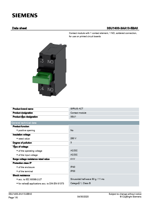
西门子 sirius 系列 3SU1400-3AA10-5BA0 接触模块 产品说明说明书
● at DC — rated value
Power Electronics Contact reliability
Auxiliary circuit Design of the contact of auxiliary contacts Number of NC contacts for auxiliary contacts ● lagging switching Number of NO contacts for auxiliary contacts ● leading contact Operating current at AC-12 ● at 24 V rated value ● at 48 V rated value ● at 110 V rated value ● at 230 V rated value Operating current at AC-15 ● at 24 V rated value ● at 48 V rated value ● at 110 V rated value ● at 230 V rated value Operating current at DC-12 ● at 24 V rated value ● at 48 V rated value ● at 110 V rated value
parameter of the soldering method
Soldering point quality acc. to IPC A-610
Certificates/ approvals
1A
3A 1.5 A 0.7 A 0.3 A
Socket connection (THT)
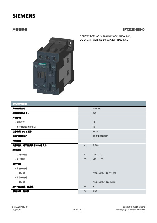
西门子SIRIUS 3RT2028-1BB40交流接触器说明书
触点负荷能力 / 辅助触点的 / 符合 UL
短路 : 熔断器熔丝的结构形式
• 用于主电路的短路保护 / 必要的 • 用于主电路的短路保护
• 对于相配类型1 / 要求的 • 对于相配类型2 / 要求的
kW
16
kW
28
kW
48
kW
18.5
kW
11
kW
18.5
kW
18.5
kW
11
kW
6
kW
10.3
18.08.2014
subject to modifications © Copyright Siemens AG 2014
短时热电流 / 时间限定到 10 s 损耗的有效功率 / AC-3 时 / 400 V 时 / 工作电流的测定值时 / 每根导 线 空载运行频率
产品数据表
3RT2028-1BB40
CONTACTOR, AC-3, 18.5KW/400V, 1NO+1NC, DC 24V, 3-POLE, SZ S0 SCREW TERMINAL
综合技术数据: 产品品牌名称 接触器的结构尺寸 产品扩展
• 辅助开关 • 用于通讯的功能模块 防护等级 IP / 正面的 防电击接触保护 污染程度 安装高度 / 对于高度高于NN / 最大的 环境温度 • 在储存期间 • 运行期间 耐冲击性 • 方波冲击时
工作功率 • 在AC-1时 / 在230 V时 / 测定值 • 在AC-1时 / 在400 V时 / 测定值 • 在AC-1时 / 在690 V时 / 测定值 • 在AC-2时 • 在400 V时 / 额定值 • 在AC-3时 • 在230 V时 / 测定值 • 在400 V时 / 测定值 • 在690 V时 / 测定值 • 在AC-4时 • 在400 V时 / 额定值
西门子SIRIUS继电器 时间继电器

3RP15 1.-1A....
3RP15 25,通电延时,15 段时间设定
LED 显示
通电延时
1CO 转换触头
3RP15 25-1B...
2 CO 转换触头
3RP15 27,通电延时,2 线型,4 段时间设定
1 NO 常开延时触 头,半导体型
9/3
时间继电器
3RP15/3RP20 时间继电器
产品选型(续)
类型
功能
通电
时间设定范围 t
额定控制电压 AC 50/60Hz DC
订货号
触头闭合
旋钮可调
触头断开
V
V
3RP15 3.,断电延时带辅助电压,1 段时间设定
LED 显示
断电延时带辅助电压
1CO 转换触头
0.5 - 10s 1.5 - 30s
器
9/13 3RP20 端子图
9/14 星三角时间继电器应用举例
SIRIUS
9/203
SIRIUS
时间继电器
3RP15/3RP20 时间继电器
概述
应用
通电延时:
• 抑制噪声脉冲 • 平稳起动电机,对线路电压冲击小
断电延时:
• 在断开控制电源后,仍能继续运行(风扇运转) • 电源故障时,可实现急停或将设备或系统置于一个特定的状态
SIRIUS
SIRIUS 继电器
时间继电器
继
监控继电器
电
器
接口继电器和变送器
9/102
SIRIUS 继电器
时间继电器
9/2 概述、应用、优点 9/3 产品选型
9/8 技术参数
西门子sirius软起动器

SIRIUS 软起动器:出色地保护电机和机械设备,减轻电网压力宣传手册• 2010SIRIUSAnswers for industry.SIRIUS — 适合各种应用的理想软起动器目前,三相电机通常作为用户最终选择的驱动形式。
但在很多情况下,直接起动或星三角起动等传统起动方式会引起机械冲击、电网电压骤降等问题。
为此,西门子公司推出了全系列的软起动解决方案,即 SIRIUS 软起动器,包括标准型和高性能型,可适用于任何应用场合。
SIRIUS 软起动器能够平稳起动/停止三相电机,轻松、高效的实现前瞻性的最佳设备解决方案。
2三相电机的软起动SIRIUS 软起动器—优点一览• 软起动,软停车• 平滑起动• 降低电机起动时的峰值电流• 避免起动过程中引起电网电压波动• 减轻电网压力• 减轻传动系统中的机械冲击• 与其它起动器相比,显著节省空间和布线• 降低维护费用• 操作简便• 可与其它 SIRIUS 设备完美搭配软起动器的工作原理软起动器通过限制起动电流和起动转矩,能够可靠地防止起动过程中的机械冲击和电网压降。
通过对可控硅导通角的控制,来降低电机起动电压,并在设定的起动时间内,将电机起动电压升高到额定电压。
凭借这种电机电压的无阶跃控制,可以根据被驱机器的负载特性对电机进行调节,平缓加速机械设备,从而显著提高机械设备的运行性能,延长其使用寿命。
总之:通过软起动/软停车,能够有效保护所连设备,确保生产运行平稳、可靠。
可以与负载馈电器配合使用吗?当然可以。
结合断路器,例如 SIRUIS 3RV,可以很容易地组成小型非熔断器保护的负载馈电装置。
不仅如此,由于该产品集成了过载保护功能,用户还可快速实现节省空间的带熔断器保护的负载馈电装置1)。
如何进行连接?连接方式与其它 SIRIUS 设备完全相同:使用螺钉型接线端子或弹簧型接线端子。
根据需要,也可使用其它连接方式。
能否进行通讯?当然。
西门子软起动器具有通讯功能。
SIRIUS(国产)样本

当在电源侧保护控制变压器时,接通变压器时产生的瞬时电流 经常会引起保护机构的误脱扣。
因此,用于保护变压器的 3RV64/3RV54 断路器短路脱扣值均按 20 倍的额定电流值进行固定设置,因而可以用来在电源侧保护 浪涌峰值电流是额定电流 30 倍的变压器。
浪涌电流较低的控制变压器不需要使用此类断路器,可使用用 于电机保护的 3RV60/3RV50 电动机保护断路器。
SIRIUS(国产)断路器
3RV6. 11 (S00) 3RV6. 21 (S0) 3RV5. 31 (S2) SIRIUS(国产)接触器和中间继电器
3RV5. 41 (S3)
3RT60 1/3RH61 3RT60 2 (S0) (S00) SIRIUS(国产)热过载继电器
3RT50 3 (S2)
3RT50 4 (S3)
欠压脱扣器
分励脱扣器
三相绝缘母线系统
门耦合旋转操作机构
与接触器的连接模块
固定安装件
页数
√ 有此功能或可使用此附件 - 没有此功能或不可使用此附件
3RV60/3RV50
3RV63/3RV53
3RV64/3RV54
√ 1) √ - - S00, S0, S2, S3
至 16 至 40 至 50 至 100 690(交流)2)
通用数据
设计
螺钉接线端子 S00/S0 规格的 3RV6 断路器,配有带紧固螺钉和压线片的端 子,允许连接 2 根截面积不同的导线。 S2 和 S3 规格的 3RV5 断路器的盒式接线端子同样可以连接 2 根截面积不同的导线。除了 S3 规格的断路器(配有 4 mm 六角 螺钉)外,所有的端子螺钉都用 2 号米字型螺丝刀紧固。 为了把导线连接到电缆固定头或接线柱上,可以拆除 S3 电动机 保护断路器的盒式端子,并加装 3RT59 46-4EA1 端子防护罩, 用于指触防护,并保证必要的电气间隙和爬电距离。
西门子3UG监控继电器说明书
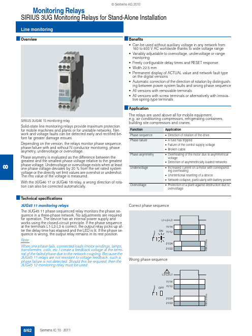
8■Overview SIRIUS 3UG46 15 monitoring relaySolid-state line monitoring relays provide maximum protection for mobile machines and plants or for unstable networks. Net-work and voltage faults can be detected early and rectified be-fore far greater damage ensues.Depending on the version, the relays monitor phase sequence, phase failure with and without N conductor monitoring, phase asymetry, undervoltage or overvoltage.Phase asymetry is evaluated as the difference between the greatest and the smallest phase voltage relative to the greatest phase voltage. Undervoltage or overvoltage exists when at least one phase voltage deviates by 20 % from the set rated system voltage or the directly set limit values are overshot or undershot. The rms value of the voltage is measured.With the 3UG46 17 or 3UG46 18 relay, a wrong direction of rota-tion can also be corrected automatically.■Benefits•Can be used without auxiliary voltage in any network from 160 to 600 V AC worldwide thanks to wide voltage range •Variably adjustable to overvoltage, undervoltage or range monitoring•Freely configurable delay times and RESET response •Width 22.5 mm•Permanent display of ACTUAL value and network fault type on the digital versions•Automatic correction of the direction of rotation by distinguish-ing between power system faults and wrong phase sequence •All versions with removable terminals•All versions with screw terminals or alternatively with innova-tive spring-type terminals■ApplicationThe relays are used above all for mobile equipment,e.g. air conditioning compressors, refrigerating containers, building site compressors and cranes.■Technical specifications3UG45 11 monitoring relaysThe 3UG45 11 phase sequenced relay monitors the phase se-quence in a three-phase network. No adjustments are required for operation. The device has an internal power supply and works using the closed-circuit principle. If the phase sequence at the terminals L1-L2-L3 is correct, the output relay picks up af-ter the delay time has elapsed and the LED is lit. If the phase se-quence is wrong, the output relay remains in its rest position.Note:When one phase fails, connected loads (motor windings, lamps, transformers, coils, etc.) create a feedback voltage at the termi-nal of the failed phase due to the network coupling. Because the 3UG45 11 relays are not resistant to voltage feedback, such a phase failure is not detected. Should this be required, then the 3UG45 12 monitoring relay must be used.Correct phase sequenceWrong phase sequenceFunction ApplicationPhase sequence •Direction of rotation of the drive Phase failure•A fuse has tripped•Failure of the control supply voltage •Broken cablePhase asymmetry•Overheating of the motor due to asymmetrical voltage•Detection of asymmetrically loaded networksUndervoltage•Increased current on a motor with correspond-ing overheating•Unintentional resetting of a device•Network collapse, particularly with battery powerOvervoltage•Protection of a plant against destruction due to overvoltage8 3UG45 12 monitoring relaysThe 3UG45 12 line monitoring relay monitors three-phase net-works with regard to phase sequence, phase failure and phaseunbalance of 10 %. Thanks to a special measuring method, aphase failure is reliably detected in spite of the wide voltagerange from 160 to 690 V and feedback through the load of up to90 %. The device has an internal power supply and works usingthe closed-circuit principle. No adjustments are required. Whenthe mains voltage is switched on, the green LED is lit. If thephase sequence at the terminals L1-L2-L3 is correct, the outputrelay picks up. If the phase sequence is wrong, the red LEDflashes and the output relay remains in its rest position. If aphase fails, the red LED is permanently lit and the output relaydrops.Note:The red LED is a fault diagnostic indicator and does not show thecurrent relay status. The 3UG45 12 monitoring relay is suitablefor line frequencies of 50/60 Hz.Phase failureWrong phase sequence3UG45 13 monitoring relaysThe 3UG45 13 line monitoring relay monitors three-phase net-works with regard to phase sequence, phase failure, phaseasymetry and undervoltage of 20 %. The device has an internalpower supply and works using the closed-circuit principle. Thehysteresis is 5 %. The integrated response delay time is adjust-able from 0 to 20 s and responds to undervoltage. If the directionis incorrect, the device switches off immediately. Thanks to aspecial measuring method, a phase failure is reliably detected inspite of the wide voltage range from 160 to 690 V and feedbackthrough the load of up to 80%. When the mains voltage isswitched on, the green LED is lit. If the phase sequence at theterminals L1-L2-L3 is correct, the output relay picks up. If thephase sequence is wrong, the red LED flashes and the outputrelay remains in its rest position. If a phase fails, the red LED ispermanently lit and the output relay drops.Note:The red LED is a fault diagnostic indicator and does not show thecurrent relay status. The 3UG45 13 monitoring relay is suitablefor line frequencies of 50/60 Hz.Phase failure and undervoltageWrong phase sequence8/6383UG46 14 monitoring relaysThe 3UG46 14 line monitoring relay has a wide voltage rangeand an internal power supply. The device is equipped with a dis-play and is parameterized using three buttons. It monitors three-phase networks with regard to phase asymetry from 5 to 20%,phase failure, undervoltage and phase sequence. The hystere-sis is adjustable from 1 to 20 V. In addition the device has a re-sponse delay and ON-delay from 0 to 20 s in each case. The in-tegrated response delay time responds to phase asymetry andundervoltage. If the direction is incorrect, the device switches offimmediately. Thanks to a special measuring method, a phasefailure is reliably detected in spite of the wide voltage range from160 to 690 V and feedback through the load of up to 80%.The 3UG46 14 monitoring relay can be operated on the basis ofeither the open-circuit or closed-circuit principle and with man-ual or auto RESET.With the closed-circuit principle selected3UG46 15/ 3UG46 16 monitoring relaysThe 3UG46 15/3UG46 16 line monitoring relay has a wide volt-age range and an internal power supply. The device is equippedwith a display and is parameterized using three buttons. The3UG46 15 device monitors three-phase networks with regard tophase failure, undervoltage, overvoltage and phase sequence.The 3UG46 16 monitoring relay monitors the neutral conductoras well. The hysteresis is adjustable from 1 to 20 V. In additionthe device has two separately adjustable delay times for over-voltage and undervoltage from 0 to 20 s in each case. If the di-rection is incorrect, the device switches off immediately. Thanksto a special measuring method, a phase failure is reliably de-tected in spite of the wide voltage range from 160 to 690 V andfeedback through the load of up to 80%.The 3UG46 15/ 3UG46 16 monitoring relay can be operated onthe basis of either the open-circuit or closed-circuit principle andwith manual or auto RESET.With the closed-circuit principle selected8/648 3UG46 17/ 3UG46 18 monitoring relaysThe 3UG46 17/ 3UG46 18 line monitoring relay has an internalpower supply and can automatically correct a wrong direction ofrotation. Thanks to a special measuring method, a phase failureis reliably detected in spite of the wide voltage range from160 to 690 V AC and feedback through the load of up to 80%.The device is equipped with a display and is parameterized us-ing three buttons. The 3UG46 17 line monitoring relay monitorsthree-phase networks with regard to phase sequence, phasefailure, phase unbalance, undervoltage and overvoltage. The3UG46 18 monitoring relay monitors the neutral conductor aswell. The hysteresis is adjustable from 1 to 20 V. In addition thedevice has delay times from 0 to 20 s in each case for overvolt-age, undervoltage, phase failure and phase unbalance. The3UG46 17/ 3UG46 18 monitoring relay can be operated on thebasis of either the open-circuit or closed-circuit principle andwith manual or auto RESET. The one changeover contact is usedfor warning or disconnection in the event of power system faults(voltage, unbalance), the other responds only to a wrong phasesequence. In conjunction with a contactor reversing assembly itis thus possible to change the direction automatically.With the closed-circuit principle selectedCircuit diagramsType3UG45 11 ... 3UG45 13, 3UG46 14 ... 3UG46 18General dataRated insulation voltage U iPollution degree 3Overvoltage category III acc. to EN 60664-1V690Rated impulse withstand voltage kV6Control circuitLoad capacity of the output relay•Conventional thermal current I th A5Rated operational current I e at•AC-15/24 ... 400 V A3•DC-13/24 V A1•DC-13/125 V A0.2•DC-13/250 V A0.1Minimum contact load at 17 V DC mA5Electrical endurance AC-15Million oper-ating cycles0.1Mechanical endurance Million oper-ating cycles103UG45 11-.A,3UG45 12-.A3UG45 11-.B, 3UG45 12-.B,3UG45 13, 3UG46 14,3UG46 15, 3UG46 173UG46 16,3UG46 18Note:It is not necessary to protect themeasuring circuit for device pro-tection. The protective device forline protection depends on thecross-section used.8/658/66*You can order this quantity or a multiple thereof.8■Selection and ordering dataPU (UNIT, SET, M)= 1PS*= 1 unit PG = 101✓ Function available -- Function not available1)Absolute limit values.2)1 CO contact each and 1 tripping delay time each for U min and U max .3)1 CO contact each for power system fault and phase sequence correction.For accessories, see page 8/90.Hysteresis Over-ON-delay Trippingdelay Rated control Screw terminalsDTSpring-type 3UG45 11-2BP203UG45 11-1AP203UG46 15-1CR203UG46 16-1CR203UG45 12-2BR203UG46 17-1CR203UG46 18-1CR208■OverviewSIRIUS 3UG46 31 monitoring relayThe relays monitor single-phase AC voltages (rms value) andDC voltages against the set threshold value for overshoot andundershoot. The devices differ with regard to their power supply(internal or external).■Benefits•Versions with wide voltage supply range•Variably adjustable to overvoltage, undervoltage or rangemonitoring•Freely configurable delay times and RESET response•Width 22.5 mm•Display of ACTUAL value and status messages•All versions with removable terminals•All versions with screw terminals or alternatively with innova-tive spring-type terminals■Application•Protection of a plant against destruction due to overvoltage•Switch-on of a plant at a defined voltage and higher•Protection against overloaded control supply voltages,particularly with battery power•Threshold switch for analog signals from 0.1 to 10V■Technical specifications3UG46 33 monitoring relaysThe 3UG46 33 voltage monitoring relay has an internal powersupply and performs overshoot, undershoot or range monitoringof the voltage depending on how it is parameterized. The deviceis equipped with a display and is parameterized using threebuttons.The operating and measuring range extends from 17 to275V AC/DC. The threshold values for overshoot or undershootcan be freely configured within this range. If one of these thresh-old values is reached, the output relay responds according tothe set principle of operation as soon as the tripping delay timehas elapsed. This delay time U Del can be set from 0.1 to 20s likethe ON-delay time on Del.The hysteresis is adjustable from 0.1 to 150V. The device can beoperated on the basis of either the open-circuit or closed-circuitprinciple and with manual or auto RESET. One output change-over contact is available as signaling contact.With the closed-circuit principle selectedOvervoltageUndervoltageRange monitoring8/6783UG46 31/ 3UG46 32 monitoring relaysThe 3UG46 31/3UG46 32 voltage monitoring relay is suppliedwith an auxiliary voltage of 24 V AC/DC or 24 to 240V AC/DCand performs overshoot, undershoot or range monitoring of thevoltage depending on how it is parameterized. The device isequipped with a display and is parameterized using threebuttons.The measuring range extends from 0.1 to 60 V or 10 to600V AC/DC. The threshold values for overshoot or undershootcan be freely configured within this range. If one of these thresh-old values is reached, the output relay responds according tothe set principle of operation as soon as the delay time haselapsed. This delay time U Del can be set from 0.1 to 20 s.The hysteresis can be set from 0.1 to 30 V or 0.1 to 300 V. Thedevice can be operated on the basis of either the open-circuit orclosed-circuit principle and with manual or auto RESET. One out-put changeover contact is available as signaling contact.With the closed-circuit principle selectedOvervoltageUndervoltageRange monitoringCircuit diagrams3UG46 313UG46 323UG46 33 General dataRated insulation voltage U iPollution degree 3Overvoltage category III acc. to EN 60664-1V690Rated impulse withstand voltage U imp kV6Measuring circuitPermissible measuring range single-phase AC/DC voltage V0.1 ... 6810 ... 65017 (275)Setting range single-phase voltage V0.1 ... 6010 ... 60017 (275)Measuring frequency Hz40 (500)Control circuitLoad capacity of the output relay•Conventional thermal current I th A5Rated operational current I e at•AC-15/24 ... 400 V A3•DC-13/24 V A1•DC-13/125 V A0.2•DC-13/250 V A0.1Minimum contact load at 17 V DC mA53UG46 31-.AA30,3UG46 32-.AA303UG46 31-.AW30,3UG46 32-.AW303UG46 33Note:It is not necessary to protect themeasuring circuit for deviceprotection. The protective devicefor line protection depends on thecross-section used.8/688/69*You can order this quantity or a multiple thereof.8■Selection and ordering data•Digitally adjustable, with illuminated LC display •Auto or manual RESET•Open or closed-circuit principle •1 CO contactPU (UNIT, SET, M)= 1PS*= 1 unit PG = 101Absolute limit values.For accessories, see page 8/90.Measuring rangeHysteresis3UG46 31-1AA303UG46 33-2AL30。
西门子-3RP 时间继电器
时间继电器电子式 3RP1/3RP2 时间继电器可用于所有需要进行延时操作的起动、保护以及开环和闭环控制回路。
借助其业已验证的设计概念和紧凑的节约空间设计,成为所有工业领域中电气柜、面板和控制器厂家理想的定时设备选择。
通电延时:● 抑制噪声脉冲● 平稳起动电机,对线路电压冲击小断电延时:● 在断开控制电源后,仍能继续运行(风扇运转)● 电源故障时,可实现急停或将设备或系统置于一个特定的状态星/三角转换:● 为防止相间短路,电机需在50ms 内从星型电路转换到三角形电路● 所有型号都采用可拆卸端子● 所有型号都可选用螺钉型端子或笼卡式端子● 一套可选的标签用于标明多功能时间继电器所设定的功能● 7 种基本型号即能满足各种应用● 宽电压范围的多功能时间继电器,使用更为便利● 最佳的性价比● 强制断开,硬金镀层触点(可用于DIN EN 954 1 Category 2安全回路,并可和电子式控制系统配套使用)● 密封性外壳,可确保按设定参数运行3/2Sirius 继电器时间继电器1)当设定“∞” 时,无延时功能,仅用于现场检测。
如:检测开关动作性能。
2)线圈电压工作范围 0.8 ~ 1.1 x U s 。
3)线圈电压工作范围 0.7 ~ 1.1 x U s 。
3/3时间继电器1)当设定“∞”时,无延时功能,仅用于现场检测。
如:检测开关动作性能。
2)线圈电压工作范围 0.7 ~ 1.25 x U s。
3)线圈电压工作范围 0.85 ~ 1.1 x U s。
4)线圈电压工作范围 0.8 ~ 1.1 x U s。
3/4Sirius 继电器时间继电器1)功能见 3RP1901-0 功能标牌套装。
2)产品带安全电气隔离功能。
3)当设定“∞”时,无延时功能,仅用于现场检测。
4)线圈电压工作范围 0.8 ~ 1.1 x U s 。
5)线圈电压工作范围 0.7 ~ 1.1 x U s 。
3/5类型功能字母应用订货号编码8 功能通电延时 A用于具备 1CO 3RP19 01 - 0A带辅助电压的断电延时 B转换触头的带辅助电压的通电延时及断电延时 C 时间继电器间隔脉冲D短时接通E带辅助电压的短时分断F带辅助电压的短时接通G带辅助电压的辅助通电延时H16 功能通电延时 A用于具备 2CO 3RP19 01 - 0B带辅助电压的断电延时 B转换触头的带辅助电压的通电延时及断电延时 C 时间继电器间隔脉冲D短时接通E带辅助电压的短时分断F带辅助电压的短时接通G带辅助电压的辅助通电延时H!带瞬动触点的通电延时A!带辅助电压和瞬动触点的断电延时B!带辅助电压和瞬动触点的通、断电延时C!带瞬动触点的间隔脉冲D!带瞬动触点的短时接通E!带辅助电压和瞬动触点的短时分断F!带辅助电压和瞬动触点的间隔脉冲G!星三角转换YΔ密封罩防止无关人员误操作用于具备1 转换3RP19 02或 2 转换触头的时间继电器镙钉固装用于具备1 转换3RP19 03插脚或 2 转换触头的时间继电器时间继电器产品选型(续)功能时间继电器通电触头闭合触头打开1 转换触头A 通电延时E短时接通B 带辅助电压的断电延时 F带辅助电压的短时分断C 带辅助电压的通电延时及断电延时 G带辅助电压的短时接通(t = t ON =t OFF) (输出端脉冲形成与励磁持续时间无关)D 间隔脉冲 (脉冲间隔为 1:1) H 带辅助电压的辅助通电延时3RP19 01-0A盖板与插脚Sirius 继电器时间继电器3/7时间继电器1)如果无特殊注明。
- 1、下载文档前请自行甄别文档内容的完整性,平台不提供额外的编辑、内容补充、找答案等附加服务。
- 2、"仅部分预览"的文档,不可在线预览部分如存在完整性等问题,可反馈申请退款(可完整预览的文档不适用该条件!)。
- 3、如文档侵犯您的权益,请联系客服反馈,我们会尽快为您处理(人工客服工作时间:9:00-18:30)。
SIRIUS
继
电
器
9/102时间继电器
SIRIUS 继电器
监控继电器
接口继电器和变送器
SIRIUS 继电器
9/2
时间继电器
3RP15/3RP20 时间继电器
电子式 3RP1/3RP2 时间继电器可用于所有需要进行延时操作的起动、保护以及开环和闭环控制回路。
借助其业已验证的设计概念和紧凑的节约空间设计,成为所有工业领域中电气柜、面板和控制器厂家理想的定时设备选择。
通电延时:
• 抑制噪声脉冲
• 平稳起动电机,对线路电压冲击小
断电延时:
• 在断开控制电源后,仍能继续运行(风扇运转)
• 电源故障时,可实现急停或将设备或系统置于一个特定的状态
星/三角转换:
• 为防止相间短路,电机需在50ms 内从星型电路转换到三角形电路
• 所有型号都采用可拆卸端子
• 所有型号都可选用螺钉型端子或笼卡式端子
• 一套可选的标签用于标明多功能时间继电器所设定的功能• 7 种基本型号即能满足各种应用
• 宽电压范围的多功能时间继电器,使用更为便利• 最佳的性价比
• 强制断开,硬金镀层触点(可用于DIN EN 954 1 Category 2安全回路,并可和电子式控制系统配套使用)• 密封性外壳,可确保按设定参数运行
SIRIUS 继电器
9/3
时间继电器
3RP15/3RP20 时间继电器
1)当设定“∞” 时,无延时功能,仅用于现场检测。
如:检测开关动作性能。
2)线圈电压工作范围 0.8 ~ 1.1 x U s 。
3)线圈电压工作范围 0.7 ~ 1.1 x U s 。
SIRIUS
继
电器
9/4
时间继电器
3RP15/3RP20 时间继电器
1)当设定“∞”时,无延时功能,仅用于现场检测。
如:检测开关动作性能。
2)线圈电压工作范围 0.7 ~ 1.25 x U s 。
3)线圈电压工作范围 0.85 ~ 1.1 x U s 。
4)线圈电压工作范围 0.8 ~ 1.1 x U s 。
SIRIUS 继电器
9/5
时间继电器
3RP15/3RP20 时间继电器
1)功能见 3RP1901-0 功能标牌套装。
2)产品带安全电气隔离功能。
3)当设定“∞”时,无延时功能,仅用于现场检测。
4)线圈电压工作范围 0.8 ~ 1.1 x U s 。
5)线圈电压工作范围 0.7 ~ 1.1 x U s 。
SIRIUS 继电器
9/6
时间继电器
3RP15/3RP20 时间继电器
SIRIUS 继
电器
9/7
时间继电器
3RP15/3RP20 时间继电器
SIRIUS
继电器
9/8
时间继电器
3RP15/3RP20 时间继电器
1)如果无特殊注明。
2)最大浪涌电流 1A/100ms 。
3)对于 3RP15 05-.R :NC 触点-> I e = 1A 。
4)防熔焊电流 I k ≥ 1kA ,符合 IEC 60947-5-1 标准。
5)对于 3RP15 05-.BW30,最小接通时间为 150ms 。
6)为保证正确动作,必须保证最小接通时间。
SIRIUS
继电器
9/9
时间继电器
3RP15/3RP20 时间继电器
1)如果无特殊注明。
2)防熔焊电流 I k ≥ 1 kA 符合 IEC 60947-5-1 标准。
SIRIUS 继电器
时间继电器
3RP15/3RP20 时间继电器
SIRIUS 继电器
时间继电器
3RP15/3RP20 时间继电器
SIRIUS 继电器
时间继电器
3RP15/3RP20 时间继电器
SIRIUS 继电器
时间继电器
3RP15/3RP20 时间继电器
注: 触点 17/18 只在“Y ”状态闭合,在“∆”状态或未上电状态均打开。
SIRIUS 继电器
备注
时间继电器。
