1-电气说明书
电气断路器控制系统操作手册说明书
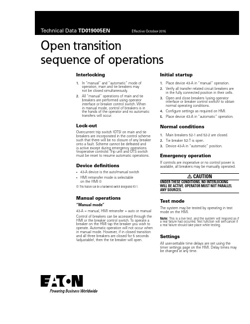
Open transition sequence of operationsInterlocking1. In “manual” and “automatic” mode ofoperation, main and tie breakers maynot be closed simultaneously.2. All “manual” operations of main and tiebreakers are performed using operatorinterface or breaker control switch. Whenin manual mode, control of breakers is inthe hands of the operator and no automatictransfers will occur.Lock-outOvercurrent trip switch (OTS) on main and tie breakers are incorporated in the control scheme such that there will be no closure of any breaker onto a fault. Scheme cannot be defeated andis active except during emergency operations (inoperative controls). Trip unit and OTS switch must be reset to resume automatic operations.Device definitions• 43-A device is the auto/manual switch• HMI retransfer mode is selectableon the HMI aa This feature can be a hardwired switch designated 43-1. Manual operations“Manual mode”43-A = manual, HMI retransfer = auto or manual Control of breakers can be accessed through the HMI or the breaker control switch. To operate a breaker on the HMI tap the breaker you wish to operate. Automatic operation will not occur when in manual mode. However, if in closed transition and all three breakers are closed for 5 seconds (adjustable), then the tie breaker will open.Initial startup1. Place device 43-A in “manual” operation.2. Verify all transfer related circuit breakers arein the fully connected position in their cells. 3. Open and close breakers (using operatorinterface or breaker control switch) to obtainnormal operating conditions.4. Configure settings as required on HMI.5. Place device 43-A in “automatic” operation.Normal conditions1. Main breakers 52-1 and 52-2 are closed.2. Tie breaker 52-T is open.3. Device 43-A in “automatic” position.Emergency operationIf controls are inoperative or no control power is available, all breakers may be manually operated.m CAUTIONUNDER THESE CONDITIONS, NO INTERLOCKING WILL BE ACTIVE. OPERATOR MUST NOT PARALLEL ANY SOURCES.Test modeThe system may be tested by operating in test mode on the HMI.ooee:N This is a live test, and the system will respond as if a real failure had occurred. Test function will self-cancel if a real failure should take place while testing.SettingsAll user-settable time delays are set using the timer settings page on the HMI. Delay times may be changed at any time.Eaoon1000 Eaton Boulevard Cleveland, OH 44122 United States © 2015 EatonAll Rights ReservedPrinted in USAPublication No. TD019005EN / Z17417 October 2015Eaton is a registered trademark.All other trademarks are propertyof their respective owners.Open transition s equence of operationsTechnical Data TD019005EN Effective October 2015Sequence of automatic operations “Open transition switching”43-A = auto, HMI retransfer = autoSee normal conditions for initial configuration.ooee:N Open-transition transfers between live sources are time-delayed in neutral, to prevent back-emf damage.A. Loss of utility power at main 52-11. Device 27/47-1 detects loss of normal voltage.2. Time delay 5 seconds (adjustable 0–60 seconds).3. Main 52-1 opens.4. Time delay 2 seconds (adjustable 0–10 seconds),and then tie breaker 52-T closes.B. Loss of utility power at main 52-21. Device 27/47-2 detects loss of normal voltage.2. Time delay 5 seconds (adjustable 0–60 seconds).3. Main 52-2 opens.4. Time delay 2 seconds (adjustable 0–10 seconds),and then tie breaker 52-T closes.C. Loss of utility power at main 52-1 and 52-2No action is taken.D. Return of normal voltage to main 52-1(following sequence “A” above)1. Device 27/47-1 detects normal voltage.2. Time delay 10 seconds (adjustable 0–60 seconds).3. Tie breaker 52-T opens.4. Time delay 2 seconds (adjustable 0–10 seconds),and then main 52-1 closes.E. Return of normal voltage to main 52-2(following sequence “B” above)1. Device 27/47-2 detects normal voltage.2. Time delay 10 seconds (adjustable 0–60 seconds).3. Tie breaker 52-T opens.4. Time delay 2 seconds (adjustable 0–10 seconds),and then main 52-1 closes.Sequence of automatic operations “Manual re-transfer”43-A = auto, HMI retransfer = manualSee normal conditions for initial configuration.ooee:N Retransfer following return of a failed source is initiated by operator. However, if second source fails, followed by return of the first-failed source, the system will transfer to the live source and remain single-ended.A. Loss of utility power at main 52-11. Device 27/47-1 detects loss of normal voltage.2. Time delay 5 seconds (adjustable 0–60 seconds).3. Main 52-1 opens.4. Time delay 2 seconds (adjustable 0–10 seconds),and then tie breaker 52-T closes.B. Loss of utility power at main 52-21. Device 27/47-2 detects loss of normal voltage.2. Time delay 5 seconds (adjustable 0–60 seconds).3. Main 52-2 opens.4. Time delay 2 seconds (adjustable 0–10 seconds),and then tie breaker 52-T closes.C. Loss of utility power at main 52-1 and 52-2No action is taken.D. Return of normal voltage to main 52-1(following sequence “A” above)No action is taken, requires manual transfer by operator:1. Set 43-A switch to manual.2. Use breaker control switches.Or1. Navigate to one-line screen on HMI.2. Press “initiate retransfer” button on HMI screen.E. Return of normal voltage to main 52-2(following sequence “B” above)No action is taken, requires manual transfer by operator:1. Set 43-A switch to manual.2. Use breaker control switches.Or1. Navigate to one-line screen on HMI.2. Press “initiate retransfer” button on HMI screen.。
电气说明书

共11页第2页电气说明书 ZL866-601-01SM一.概述本船为新建的蟹笼船(其总吨位小于500),航行于近海区域。
本船电气部分按照1998年版《钢质海洋渔船建造规范》,2000年《渔业船舶法定检验规则》及修改通报的有关规定进行设计。
国产电气设备和材料,除另有注明者外,应执行我国有关部门颁发的国家标准、行业标准和企业标准。
一些重要的电气系统和设备,应具备ZY渔检局签发的证书。
有防爆要求的电气设备和部件,还应具备有关部门签发的防爆等级证书。
所有电气设备应按规范的要求。
配备相应的备品和备件。
二、电制本船采用以下电制:—400V,3相,50Hz,四线绝缘制--主电源—400V,3相,50Hz,四线绝缘制--动力装置—230V。
单相,50Hz,双线绝缘制--照明系统、船内助航及通信系统、船内、船员生活用电设备—24V,直流,双流,双线绝缘制--应急照明系统、航行灯和信号灯、助航及通信系统的应急供电等三、电源装置1、发电机本船设No.1、No.2、No.3三台船用三相同步交流发电机其额定参数如下:共11页第3页电气说明书 ZL866-601-01SMNo.1交流发电机(6170主机轴带)型号:STC-H-24额定电压 AC400V额定功率50Hz额定功率 24kW额定电流43.2A额定功率因素0.8(滞后)绝缘等级: F防护等级:IP23冷却方式自然通风No.2交流发电机(6135Ca辅机轴带)型号:STC-H-24额定电压 AC400V额定频率50Hz额定功率 24kW额定电流43.2A额定功率因数0.8(滞后)绝缘等级 F防护等级IP23冷却方式自然通风No.3交流发电机(停泊发电机,S195辅机轴带))型号:TFX-H-8额定电压 AC400V额定频率50Hz额定功率8kW额定电流14.4A额定功率因数0.8(滞后)绝缘等级 F护等级IP23冷却方式自然通风另配一台WZF2000H 2Kw的直流发电机(主机轴带)。
电气使用说明书

电气使用说明书电气使用说明书篇一:3516电气操作说明书※※※※※ 操作说明书※※※※※全自动球面滚子轴承内圈滚道超精研机(电气部分)型式:3MZ3516A2009 年 01月防止危险的警告为了防止危害到使用者和调试者的身体,请遵守以下的注意事项。
这是安全警告标志,使用在机床的PL铭牌或本安装操作说明书中。
这个安全警告标志是督促在使用本机的调试者或其他操,因有危险的可能,所以在操作上要注意的一个标志。
写在上面的注意点要理解并安全操作。
标记基本上如下记那样区别使用,请特别注意。
目录1.前言 ................................................... . (4)2.安全注意事项 ................................................... (4)(a)警告 ................................................... . (4)(b)安全注意事项 ................................................... . (5)3.操作电箱 ................................................... . (6)3-1. 各部的说明 ................................................... . (6)4.触摸屏画面的构成 ................................................... .. (7)4-1. 基本画面的构成 ................................................... (7)5.加工数据 ................................................... . (8)5-1.控制参数 ................................................... . (8)5-2.转速参数 ................................................... . (9)6.各画面的详细说明 ................................................... . (10)6-1.初始操作画面 ................................................... ........... 10 6-2.手动操作画面 ................................................... ...................................................... . (10)6-3.自动运转画面 ................................................... .. (12)6-3-1.加工监视 ................................................... .. (12)6-3-2.运行条件 ................................................... .. (12)7.报警画面 ................................................... (13)7-1.报警画面 ................................................... (13)7-2.报警履历 ................................................... (13)7-3.报警项目及处理 ................................................... (14)前言及安全注意事项1.前言本机为夹住工件进行高能率、高精度超精加工的全自动球面滚子轴承内圈滚道超精研机。
电气说明书
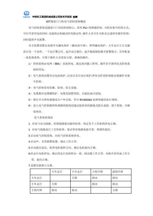
45T隧道口门机电气控制系统概述电气控制系统是隧道口门吊的控制核心,采用PLC--变频器控制,司机室集中控制方式,可以节省用电的同时,还能保证机械动作的稳定性。
操作人员可在司机室完成所有操作控制,同时提供声光报警。
安全装置设置总电源开关漏电保护(漏电流可调),照明漏电保护,大车走行左右支腿前后各一个急停、一个走行警示灯、起升高点限位,起升载荷限制器并报警指示。
另外配备一套监视系统,可便于操作人员更加方便、准确的操作。
1)控制系统由电网(380v)直接供电,满足夜间施工照明、操作室空调用电及控制系统的用电。
2)电气系统设置有过电流保护,过电压及欠电压保护;所有动作的控制能实现操作室集中控制。
3)电气控制设有防潮、防雨、防尘设施。
4)电缆都有电缆槽保护。
电缆是阻燃型的,且能抗油污侵蚀。
5)限位开关和传感器适合户外安装,符合EN 60204/1标准和最佳执行规则。
6)进入电气控制箱和传感器的接线均通过能密封的插接式接头连接,便于拆装,并确保密封。
电气系统的调试1. 对电气动力线路、控制线路做功能性检查,保证各个工作机构供电正确。
2. 对电气线路进行工艺性检查,保证所有线路连接可靠,绝缘性能好。
3.启动电气控制系统,向电气控制系统供电。
4.启动声、光等报警装置,确认工作正常。
5.启动液压泵站,检查电机旋转方向,确认电机旋向正确。
6.给走行电机供电,确认四走行电机转向一致、制动器工作正常、电机冷却风扇工作正常,旋向正确。
7.设置有联锁与互锁。
司机室内电气操作1.将左右联动台上所有开关置到初始位置。
初始位置见操作面板图;2.将司机室内电气柜总“空气开关”(HK)合上后,合上工作断路器开关(HKP1);3.将“钥匙开关”旋转至“工作”;4.将司机室门关上确保司机室门限位闭合状态,栏门关上确保护栏们限位闭合状态,司机室脚踏开关踩上确保脚踏开关闭合状态;5.按下绿色启动按钮;6.各项操作见操作表(注:工作时可随时按电铃警示,行走时将“行车警示开关”置“开”);7.结束操作时,先将联动台所有开关置“初始位置”,然后,按下“停止蘑菇按钮”,最后,断开电气柜中“空气开关”(HK)和断路器开关(HKP1)。
电气控制说明书

《电气控制技术》课程设计说明书电镀车间专用行车PLC控制系统设计学院:电气与信息工程学院学生姓名:***指导教师:罗雪莲职称/学位教授专业:电气工程及其自动化班级:电气本1301学号:**********完成时间:2016年6月摘要行车是用来在短距离内提升和移动物件的机械,是现代化工厂中用于物料输送的重要设备,电镀行车由于他的高危险性,应用它的场合更是频繁,行车对减轻工人体力劳动,提高劳动生产率起着重要的作用。
本设计中的行车要实现左右,前后及上下的三维运动,并且要准确定位,具有远距离控制,能够按照预定顺序和控制要求,自动完成一序列的工作。
在设计中采用低压电器的控制方式,控制线路的设计方面力图做到布局合理,排列均匀,原理图上有极限位置保护和必要的电气保护措施,重点分析了系统软硬件设计部分,并给出了系统硬件接线图、PLC 控制I/O端口分配表以及整体程序流程图等,实现了电镀生产自动化,提高了生产效率,降低了劳动强度。
在该生产线的控制系统中,采用了高可靠性,高稳定性,编程简单,易于使用,而且广泛应用于现代工业企业生产线过程控制中的控制器PLC。
详细分析了输送系统设备保护控制电动机原理图、程序框图、PLC 系统外部接线图。
分层次详细阐述了整个高度自动化输送系统的目标及功能,使高度自动化输送系统的结构更加清晰,层次更加分明,具有非常强的实用性。
关键词:电镀车间;PLC控制;梯形图目录1 概述 (1)1.1 电镀生产线简介及存在问题 (1)1.2 电镀车间行车专用PLC控制系统设计内容 (1)1.2.1 设备基本情况 (1)1.2.2 拖动系统 (2)1.3 电镀车间行车专用PLC控制系统设计要求 (2)2 总体方案设计 (3)2.1 控制方式选择 (3)2.1.1 方案一 (3)2.1.2 方案二 (3)2.1.3 方案比较与选择 (3)2.2 拖动方案选择 (3)2.3 信号检测装置选择 (3)2.4 指示方式选择 (3)2.5 抗电源干扰措施 (3)3 主电路设计 (5)3.1 电镀车间专用行车PLC控制系统主电路 (5)3.2 电路图 (5)4 PLC控制系统设计 (6)4.1 控制系统动作流程框图 (6)4.2 PLC选型 (6)4.3 低压电器选用 (7)4.4 I/O点分配 (7)4.5 梯形图 (9)4.6 调试过程 (12)参考文献 (13)致谢 (14)附录A 电路图 (15)1 概述1.1电镀生产线简介及存在问题随着金属加工业的发展,电镀行业在我国迅速地发展了起来,目前全国拥有五千多家厂点、二十多万职工,其规模、产量及其产值都进入世界电镀大国行列。
电气设计说明书(终版)
建筑环境与设备工程专业建筑电气课程设计说明书学生姓名骆俊文班级 2011级 2班学号 **********系别建筑设备工程系学院土木工程学院指导教师徐晓宁、郝海青2014年6月29日目录一、设计概况 (1)二、建筑负荷、供电要求 (1)三、供电主干线 (1)四、负荷计算,设备选型 (2)五、参考文献 (24)一、设计概况本课程设计为建筑供配电系统设计,设计对象是一个多层宿舍楼,该宿舍楼楼高24.6 m,共7层,首层为架空层,2~7层为宿舍,架空层面积为326.9m2,建筑面积(不含架空层)9066.72m2,建筑总面积9893.62m2,床位数1040。
具体布置见电子文档资料。
该建筑配电室设在首层,由附近的变配电所提供一路0.4kV低压电源,采用电缆穿管埋地引入建筑的A梯配电室,由配电室的低压配电柜经电缆竖井送到各用电设备。
宿舍楼配置中央空调系统,采用集中供冷方式,由区域冷站提供低温冷冻水到建筑底层的空调设备房,经板式换热器换热后,在二次侧设置冷冻水泵将冷冻水输送到末端用户;宿舍楼中央空调形式采用新风+风机盘管类型。
该住宅楼建筑平面图由电子文档资料提供。
二、建筑负荷、供电要求1、负荷计算说明宿舍负荷按单位负荷计算,每单元取负荷为2.0 kW。
其它专业提供资料:首层各功能房间设备负荷包括:(1)热交换站:冷冻水泵2台(一用一备,有变频装置),功率:18.5kW;通风用轴流风机1台,功率:180W;(2)配电房:三个,每个配电房配置通风用轴流风机1台,功率:180W;(3)弱电房:三个,每个弱电房配置通风用轴流风机1台,功率:120W;(4)社团活动房:配置通风用轴流风机1台,功率:180W;(5)空调机房:配置通风用轴流风机1台,功率:180W;(6)洗衣房:配置通风用轴流风机1台,功率:120W。
中央空调系统新风机设备功率为:180 W/台,每层配备三台新风机;用户末端风机盘管功率:46W/台。
电气说明书

1.概述本船依据有关会议的纪要和用户使用意见进行设计。
本船主要航行于武汉武钢工业港至宁波,满足长江A级航区及近海海区要求。
本船遵照CCS《钢质海船入级与建造规范》(2001)、《钢质内河船舶入级与建造规范》(2002)和ZC《船舶与海上设施法定检验规则》(1999)(非国际航行海船法定检验技术规则)、(内河船舶法定检验技术规则)进行设计,并满足其要求。
电气设备的选型、线路设计、建造、安装、试验均应满足相关的规范和规则。
电气设备及材料必须全部为船用产品并经船检认可后,方能上船安装。
2. 电制及基本参数2.1 主电源采用AC400V、50HZ、三相三线绝缘系统。
应急电源采用AC400V、50HZ三相三线绝缘系统。
2.2 动力电源采用AC380V、50HZ三相三线绝缘系统。
2.3 正常和应急照明、通讯、导航、部分生活设施采用AC220V、50HZ单相双线绝缘系统。
2.4 临时应急照明、火灾报警、警铃等采用DC24V双线绝缘系统。
3. 电源设备3.1 主柴油发电机组本船设相同容量主柴油发电机组两台,经负载计算,单台发电机组能满足任一状态用电要求,两台主发电机组互为备用。
主柴油发电机组的型号、参数如下:三相交流发电机:THXF-120型、120kW、50HZ、400V、1500r/min、cosφ=0.8,两台发电机与柴油机配套安装于机舱内。
3.2停泊柴油发电机组本船按用户的要求设停泊柴油发电机一台,仅考虑停泊时部分必要的通讯设备、部分生活照明、生活水泵和一台机舱风机、燃油废气组合锅炉等的用电,其它用电负荷由船员控制使用。
停泊柴油发电机的参数如下:三相交流同步发电机:THXF-40型、40kW、400V、50HZ、1500r/min、cosφ=0.8,防护等级IP23。
该发电机与柴油机配套安装于机舱内。
3.3应急柴油发电机组本船设应急柴油发电机组一台,经负载计算,该发电机组在船舶发生应急的情况时能满足“规范”规定的用电负荷所需用电时间的要求。
电气使用说明书

国电吉林江南热电有限公司DQ1500/1500.35悬臂式斗轮堆取料机电气系统使用说明书电气图号:DQ5918.9工程编号:15035-40长春发电设备有限责任公司二零零九年十二月审定:校核:编制:目录一.前言 (1)二.起动前的准备工作 (1)三.电源 (2)3.1上机电源 (2)3.2低压动力电源 (2)3.3低压控制电源 (2)四.电气系统的布置 (3)4.1电气室 (3)4.2司机室 (3)五.工作准备 (4)5.1锚锭抬起 (5)5.2高压电源合闸 (5)5.3控制电源合闸 (5)5.4动力电源合闸 (5)5.5夹轨器放松 (5)5.6控制方式选择 (5)六、斗轮机各机构控制 (6)6.1单动控制 (6)6.2联动控制 (10)6.3半自动控制 (13)6.4联锁控制 (15)6.5公用控制 (15)七.工作结束 (16)7.1夹轨器夹紧 (16)7.2动力电源分闸 (16)7.3控制电源分闸 (16)7.4锚锭落下 (17)八.操作安全注意事项 (17)8.1概述 (17)8.2操作注意事项 (17)8.3斗轮机在工作时需要检查注意项目 (18)8.4对于暴风的注意事项 (18)九.电气设备的维修与保养 (19)附录一:半自动取料工艺流程图 (21)附录二:半自动堆料工艺流程图 (22)一.前言1.1只有经过培训的专业操作人员才能操作本斗轮堆取料机。
1.2本斗轮机绝对不能在超过额定出力的情况下进行堆取料作业。
1.3禁止在斗轮机构未运转的情况下,悬臂碰撞料堆。
1.4禁止设备未停稳时进行重启动操作。
1.5上机高压电源带电时,禁止任何人员进入变压器室。
1.6本斗轮机司机在操作本机时应仔细观察,对于一些即使最细微的异常现象,怀疑可能会对本机造成危害,都应立即停止操作,并马上向有关人员通报。
(包括:异常声音或噪音、不正常的运转状态及相应反应、各种报警指示等)。
经检查确认并消除故障后,方可继续操作。
电气设备说明书

CHAPITRE 1L ES PREACTIONNEURS ELECTRIQUESINTRODUCTIONLes préactionneurs sont des constituants qui, sur ordre de la partie de commande, assurent la distribution de l ’énergie de puissance aux actionneurs. Dans les circuits électriques, les préactionneurs sont généralement soit un relais, soit un contacteur. Le contacteur assure en plus l ’extinction de l ’a rc électrique qui accompagne souvent la commutation de l ’énergie de forte puissance. En effet, quand on ouvre un circuit en cours de fonctionnement, le contact en cause provoque un arc électrique qui peut être dangereux pour les biens et les personnes.1. LE RELAISLe relais est un composant électrique réalisant la fonction d’interfaçage entre un circuit de commande, généralement bas niveau, et un circuit de puissance alternatif ou continu (Isolation galvanique). On distingue deux types de relais : le relais électromagnétique et le relais statique.1.1. Relais électromagnétique :1.1.1. principe :Un relais électromagnétique est constitué d ’une bobine alimentée par le circuit de commande, dont le noyau mobile provoque la commutation de contacts pouvant être placé dans un circuit de puissance. Le relais électromagnétique est réservé pour les faibles puissances.1.1.2. Caractéristiques fondamentales :∙ Tension d’alimentation : C ’e st une tension continue qui permet d ’e xciter la bobine.∙ La résistance de la bobine : paramètre permettant de déterminer le courant circulant dans le circuit de commande.∙Le courant des contacts : c ’e st le courant maximal que peut commuter les contacts de relais sans dommage.1.2. Relais statique :1.2.1. DéfinitionCe qui est vrai pour un relais électromagnétique est vrai pour un relais statique. De plus un relais statique commute de manière totalement statique, sans pièce en mouvement, conférant au composant une durée de vie quasi illimitée. La structure de base d ’un relais statiqueainsi que son fonctionnement sont comme suit :Chapitre 1 : Les préactionneurs électriques371. Le circuit d'entrée correspond àl'unité de traitement ;2. Le circuit de mise à niveau ;3. Le circuit de détection de passagede zéro permet de ne commuter le relais que si la tension secteur est pratiquement nulle ; ainsi on évitera les rayonnements dus à une commutation d'une grande valeur ; 4. La charge.Le triac TR se comporte comme un interrupteur commandé : = 0, TR est bloqué (circuit ouvert), la charge A1AlimentationTR GA2Charge1.2.2. Caractéristiques fondamentales :∙ Courant d ’emploi : courant maximal que peut commuter le contact de sortie.∙ Tension d ’entrée : c ’est la tension d ’alimentation. Elle peut être continue ou alternative.∙Tension de sortie : c ’e st la tension d ’alimentation de la charge. Elle est généralement de type alternatif.1.3. Exemple de circuit :La figure suivante présente un exemple de relais statique bien connu le MOC 341, ainsi que le montage de base le mettant en œ u vre :∙Si l'unité de commande, ici matérialisée par une porte NAND, fournit un 0 à la sortie de cette porte, la diode infrarouge conduit, ce qui fait conduire l'optotriac interne, qui à son tour commande le triac extérieur, qui devient comme un circuit fermé ; la charge (LOAD) est alors alimentée par 240V AC∙ Le relais est muni du système "zero crossing", ce qui évite de commander le triac quand la tension secteur est grande, ce qui évite des parasites de commutation.Cours de : Capteurs et actionneurs en instrumentation 382. LE CONTACTEUR2.1. Principe :Un contacteur est un relais pouvant commuter de fortes puissances grâce à un de coupure d ’ou alternative. Sa constitution est comme suit :∙ Des pôles principaux de puissance ;∙ Un contact auxiliaire (avec possibilité d'additionner au contacteur un bloc de contacts auxiliaires instantanés ou temporisés) ;∙ une armature fixe et un autre mobile ; ∙ Un ressort de rappel ; ∙ Un circuit magnétique ;∙Une bobine de commande du contacteur. Si la bobine est alimentée elle attire l ’armature mobile pour actionner les pôles de puissance ; Si elle n ’est pas alimentée, un ressort de rappel ouvre les pôles de puissance.2.2. Caractéristiques électriques :∙ Tension nominale d ’emploi Ue : C ’e st la tension entre deux pôles de puissance qui ne provoque ni échauffement ni détérioration du contacteur.∙ Courant nominale d ’emploi Ie : C’est le courant qui peut circuler dans les pôles de puissance sans provoquer ni échauffement ni détérioration du contacteur.∙Courant thermique conventionnel (Ith ) : courant qu'un contacteur en position fermée peut supporter pendant 8 heures sans que l'échauffement de la bobine ne dépasse 90°C. ∙Pouvoir de coupure : courant maximal que le contacteur peut couper.2.3. Catégories de fonctionnement et choix :Pour choisir un contacteur il faut tenir compte, en plus des caractéristiques précédentes, des catégories d ’emploi. Une catégorie d ’emploie définit, pour l ’u tilisation normale d ’un contacteur, les conditions d ’établissement et de coupure du courant, en fonction du courant nominal d ’e mploi "Ie" et de la tension nominale d ’emploi "Ue" ; elle dépend :∙ De la nature du récepteur contrôlé (résistance, moteur à cage, moteur à bagues, etc.).∙Des conditions d ’e mploi dans lesquelles s’effectuent les fermetures et les ouvertures ( moteur lancé ou calé, en cours de démarrage, freinage par contre courant , etc. ).Pour choisir un contacteur on utilise généralement les guides de choix proposés par les constructeurs :Exemple de choix : Un circuit de chauffage est composé par deux charges résistives triphasés. Chaque charge consomme un courant de 10A par phase sous une tension U = 380V.Il s ’agit de la catégorie de fonctionnement AC1. Sur le guide de choix on peut opter pour le contacteur suivant :LC1-D09 A652.5. Schémas de mise en œ u vre :Pour alimenter la bobine d ’un contacteur on peut utiliser l ’un des deux montages suivants :Si on appuie sur le bouton poussoir MA la bobine du contacteur est alimentée et ferme le contact K. Même si on relâche le bouton poussoir la bobine reste alimentée (automaintien). Pour couper l’alimentation il suffit d ’ouvrir le bouton poussoir AR.Généralement, dans une chaîne d ’énergie électrique, le préactionneur ne s ’u tilise pas seul, mais associé à une classe d ’appareillage typique : sectionneur, relais thermique, etc.3. LE SECTIONNEURLe sectionneur est un appareil de connexion qui permet d'isoler (séparer électriquement) un circuit pour effectuer des opérations de maintenance ou de modification sur les circuits électriques qui se trouvent en aval. Ainsi il permet d ’assurer la sécurité des personnes qui travaillent sur le reste de l’installation en amont.Le sectionneur ne possède aucun pouvoir de coupure, par conséquent, il ne doit pas être man œuvré en charge.Cours de : Capteurs et actionneurs en instrumentationTableau 640On trouve également des sectionneurs qui servent en plus de porte-fusible. On les désigne par "Sectionneurs porte-fusible" :Sectionneur Simple4. LES FUSIBLESLes fusibles sont des appareils de protection dont la fonction est d’ouvrir un circuit par fusion d ’un élément calibré, lorsque le courant dépasse une valeur précise, pendant un temps donné. On trouve :∙La classe gI ou gG : ce sont les fusibles d’u sage général ; ils protègent contre les surcharges et les courts-circuits.∙La classe aM : ce sont les fusibles d ’a ccompagnement M oteur prévus pour la protection contre les courts-circuits et surtout pour la protection des moteurs.5. LE RELAIS THERMIQUELe relais thermique est un appareil de protection capable de protéger contre les surcharges prolongées. Une surcharge est une élévation anormale du courant consommé par le récepteur (1 à 3 In), mais prolongée dans le temps, ce qui entraîne un échauffement de l'installation pouvant aller jusqu'à sa destruction. Le temps de coupure est inversement proportionnel à l'augmentation du courant.SymboleContact commandéLe relais thermique utilise la propriété d'un bilame formé de deux lames minces ayant des coefficients de dilatation différents. L ’apparition d ’une surcharge se traduit par l ’augmentation de la chaleur (effet joule) ; Le bilame détecte l'augmentation de chaleur, se déforme et ouvre le contact auxiliaire.3 4 Chapitre 1 : Les préactionneurs électriques41Ce contact étant convenablement p lacé dans le circuit de commande va couper l'alimentation de la bobine du contacteur qui va ouvrir ses pôles de puissances et interrompre le passage de l'énergie électrique au travers du récepteur. C’est donc l'appareillage de commande qui coupe le circuit deBilame non déforméeE X E R C IEXERCICE N°1 :distribuer l’énergie vers l’actionneur,généralement adopté. Décrire le fonctionnement du montage :Cours de : Capteurs et actionneurs en instrumentation42I C E S N O N R E S O LChapitre 1 : Les préactionneurs électriques43。
电气使用说明书

武 昌 造 船 厂
TKA6916A
使 用 说 明 书
图 3-1
共 第
24 11
页 页
1
OP015A 6FC5203-0AF0-50AA0 840D显示器
2 6FC5203-0AF10-0AA0 机床操作面板
T1 T4 T7 T10 T13
T2 T5 T8 T11 T14
T3 T6 T9 T12 T15
2. 3
搬运、运输和存储要求 搬运及运输 机床控制电柜及操作、悬挂箱等部分出厂时是包装好的,搬运 或运输时要依照包装箱上的指示吊装。 运输损坏
!!!警告
武 昌 造 船 厂
控制电柜及操作部件中的元器件如果在运输中损坏了,不经过 诊断测试,是不允许使用的,否则,可能导致人员或设备损害。
TKA6916A
自 动 换 档 ( 例 : M40S100) 主轴Ⅰ档 主轴Ⅱ档 主轴Ⅲ档 主轴Ⅳ档
M63 M64 M74 武 昌 造 船 厂 M71 M72 M73
吹气开 吹气关 万能角铣头选择 滑枕端盖选择 平旋盘选择 直角铣头选择
TKA6916A
使 用 说 明 书
码 功 能
共 24 第 9
页 页
代
M81 M82
主轴箱夹紧 主轴箱放松
武 昌 造 船 厂
TKA6916A
使 用 说 明 书
走台操纵箱按钮站说明 走台操纵箱说明
共 第
24 10
页 页
3. 3. 1
3. 1. 1 走 台 操 纵 箱 示 意 图 3-1 序 1 2 号 功 840D显 示 器 集成式机床控制面板 能
10-34 40-54
操作按钮 集成式机床控制面板备用按钮
TKA6916A
电气仪表使用说明书
电气仪表使用说明书一、安全注意事项在使用电气仪表之前,请务必阅读并遵守以下安全注意事项:1. 仅限专业人员操作:电气仪表属于专业设备,只应由受过专业培训的人员进行操作和维护。
未经过专业培训的人员请勿擅自操作,以免造成人身或财产损失。
2. 断电操作:在操作电气仪表之前,务必将其与电源断开连接,确保安全操作。
在对仪表进行维护或检修时,同样应先切断电源。
3. 防止触电:在进行操作或维护时,应确保手部干燥,并佩戴绝缘手套,以防止触电事故的发生。
4. 确保接地:在操作仪表时,请确保仪表及相关设备良好接地,以减少漏电或其他安全隐患的发生。
5. 避免过载:在使用电气仪表时,请务必遵守设备的最大负载和额定电流要求,确保设备正常工作。
二、产品概述电气仪表是一种用于测量、监测和控制电气参数的设备。
本产品具有以下特点:1. 高精度测量:电气仪表采用先进的传感技术和数字处理技术,具有高精度的电气参数测量功能。
2. 多功能显示:仪表配备了清晰易读的显示屏,可以同时显示多个电气参数,并提供相应的报警功能。
3. 远程控制:仪表支持远程控制功能,可以通过无线通讯或有线连接与其他系统进行数据交互和远程控制。
4. 安全可靠:仪表具有多种安全保护功能,如过载保护、漏电保护等,确保使用过程中的安全可靠性。
三、操作指南1. 仪表启动和关闭- 启动:在确认电气仪表与电源连接稳固后,打开电源开关,待仪表显示屏亮起并完成自检后,即可开始使用。
- 关闭:在停止使用电气仪表时,先确保所有操作已保存或记录,然后依次关闭相关电源开关,并将电气仪表与电源断开连接。
2. 参数测量和显示- 选择参数:使用仪表上的操作按钮或旋钮,选择要测量和显示的电气参数。
仪表会自动进行测量并在显示屏上显示结果。
- 切换显示:如果需要同时显示多个参数,请按照仪表说明书中的操作方法切换显示模式,以便查看不同的电气参数。
3. 报警设置和处理- 设置报警:按照仪表说明书中的操作方法,进入报警设置模式,根据实际需要设置报警阈值和报警方式。
德力西电气 CDM1塑壳断路器样本 产品说明书
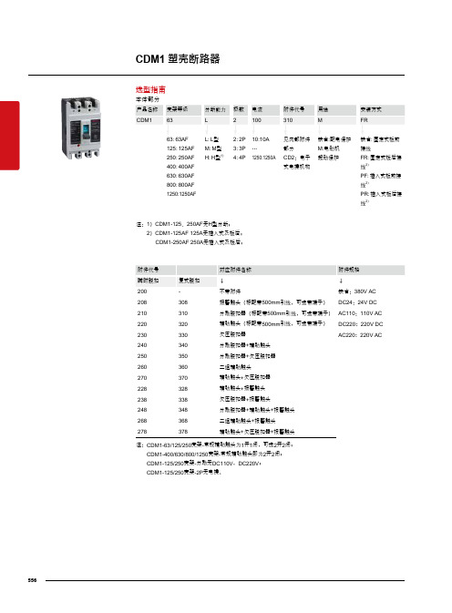
CDM1塑壳断路器本体部分选型指南注:1)CDM1-125、250AF 无H 型分断;2)CDM1-125AF 125A 无插入式及板后; CDM1-250AF 250A 无插入式及板后;200-不带附件缺省:380V AC208308报警触头(标配带500mm 引线,可选带端子)DC24:24V DC210310分励脱扣器(标配带500mm 引线,可选带端子)AC110:110V AC 220320辅助触头(标配带500mm 引线,可选带端子)DC220:220V DC 230330欠压脱扣器AC220:220V AC240340分励脱扣器+辅助触头250350分励脱扣器+欠压脱扣器260360二组辅助触头270370辅助触头+欠压脱扣器228328辅助触头+报警触头238338欠压脱扣器+报警触头248348分励脱扣器+辅助触头+报警触头268368二组辅助触头+报警触头278378辅助触头+欠压脱扣器+报警触头注:CDM1-63/125/250壳架-常规辅助触头为1开1闭,可选2开2闭;CDM1-400/630/800/1250壳架-常规辅助触头即为2开2闭; CDM1-125/250壳架-分励无DC110V ,DC220V ; CDM1-125/250壳架-2P 无电操。
556技术参数CDM1塑壳断路器*■表示有该产品注:1)CDM1-125AF 125A无插入式及板后;CDM1-250AF 250A无插入式及板后;塑壳断路器及剩余电流动作断路器B1557二级配电BCDM1塑壳断路器*■表示有该产品技术参数塑壳断路器及剩余电流动作断路器B1558二级配电CDM1塑壳断路器脱扣器安装方式及附件代号左面安装手柄右面安装□报警触头■辅助触头●分励脱扣器○欠压脱扣器引线方向208308报警触头210310分励脱扣器220320辅助触头230330欠压脱扣器240340辅助触头分励脱扣器250350分励脱扣器欠压脱扣器260360二组辅助触头270370辅助触头欠压脱扣器280380分励脱扣器二组辅助触头218318分励脱扣器报警触头228328辅助报警触头238338欠压脱扣器报警触头248348分励脱扣器辅助报警触头268368辅助触头辅助报警触头278378欠压脱扣器辅助报警触头B1 塑壳断路器及剩余电流动作断路器559B 二级配电CDM1塑壳断路器附件结构示意图CDM1 塑壳断路器560CDM1塑壳断路器欠压脱扣器当控制电压下降到线圈电压整定值以下时,断路器脱扣。
电气设备使用手册

电使器用设手备册一、前言 -------------二、操作面板操作使用说明----------三、变频器故障排查及使用说明------------四、智能数显电动机保护器使用--------------注意:设备发生异常检修时须由熟悉当地有关法规和规定,并具备相应维修资格的人士承担。
警告:为避免出现事故,设备维修时须切断电源。
一、前言·欢迎您使用本设备控制系统电器设备!在使用和维修之前,请仔细阅读此使用说明书!本说明书提供了电器设备的使用、开启及维修机器所必需的信息。
·本电器控制设备严格遵循设计标准,确保该设备能一直处于安全、高质量的运行状态,提供高度的可靠性。
·使用中如有需要更改参数和设备发生异常状况时请仔细阅读完此使用说明书在做修改和维修。
·电器柜操作规程顺序:检查线路是否有错误,电源进线电压是否正常,如无异常合上主空气4P控制开关,此时面板的电压表将显示主回路电压,电流表以3倍的形式显示主电流(在设备没有运行的情况显示为0A),同时合上所有的主回路控制空气开关(3P的和2P的),在确认所有电器设备没异常情况的同时可以合上控制回路的1P空气开关,此时控制柜里的所有电器将带电处于待工作状态。
接下来则需要去操作文本(操作面板)来控制整套设备的电器装置。
二、操作面板操作使用说明操作面板在输入了程序与PLC通讯正常,同时供如24V 电源之后出现此主页面为正常:假如没有出现此界面或界面出现显示正在通讯请检查电源和PLC之间的通讯线是否松动,如果仍然没出现请考虑是否是文本已损坏,文本当真已损坏请联系安装商给予新文本和程序。
·单击文本▼进入控制画面一:☞ⓞ:表示‘0’号键是手动和自动的切换按钮。
(现在画面处于手动状态,你要把它切换到自动状态只需在按一次‘0’号键即可切换过去;在自动状态想要切换到手动状态时也是同样操作,但会停止自动状态时的所有运行情况。
)●显示手动状态时可以对任何一个电器设备进行启动和停止。
阿特拉斯螺杆空压机电气说明书[1]
![阿特拉斯螺杆空压机电气说明书[1]](https://img.taocdn.com/s3/m/d4dff1c32cc58bd63186bdb8.png)
Mark4,Elektronikon11 Operating manual一. 控制屏(图1.1)电脑显示屏/按钮/键代号名称功能1停机按钮按此键停止空气压缩机,显示屏退出.空压机将空载运行大约30秒后停机.2启动按钮按此按键启动空压机.显示屏显示调节器的运行状态.显示屏退出(如果空压机手动调为空载时)3显示器显示出空压机的运转状态,协助需求或故障4翻业按键在显示屏上翻页5横移按键用水平箭头选择显示参数,只有向右的箭头对应的参数才能修改6LED上的电压显示开关开启时的电压7LED总报警当维护器警告或停机警告条件存在时或传感器不受控制时报警灯亮8LED总在传感器的停机功能消失或紧急停机后的情况下报警灯会闪烁. 9功能键控制并执行程序.S3 紧急停机按钮在紧急情况下立即停止空压机,在修复后.将此按钮拔出.10报警符号11自动运行符号12电源指示灯(1.1)二. 功能键使用的功能键:手动调节空压机的负荷调出或设定程序重新设定电动机的过负荷,停机,维护器信息或紧急停机.进入调节器所收集的数据.功能键都根据显示菜单的不同而不同.实际上都缩写并显示有关键的最底部一行,普通的缩写如下:缩写名称功能Add 增加指令用来增加空压机的自动启动/停机(日期) Back 返回指令返回到的选择或菜单Canc 取消当设定参数有误时.用来取消已设定的数dle 删除用来删除空压机的自动启动/停机时间Help 帮助帮助寻找Atlas Copco的内部地址Lim 上下限显示允许设定的上下极限数据Load 负载手动操作空压机负载Main 回到主目录从任一画面回到主目录Menu 菜单从主画面开始可进入子目录Menu 菜单从任一子目录返回到先前的目录Mod 修改修改设定参数Prog 编写输入将新的设定数据编写输入Rset 重新设定重新设定计时器及信息Rtrn 回归回归到前一页或前一目录Unld 空载手动操作空压机空载Xtra 额外的找寻调节器的构造模式三. 控制程序的功能程序/功能说明主屏幕简单地显示空压机的运转状态,是进入所有功能画面的出入口状态数据调出空压机的维护功能状况:停机.停机警告,维修期限快到的警告以及警告的数据,也可重新设定停机参数,马达超载和维修条件的数据.测量数据可调出:实际测量数据,还有如马达的超负荷保护这样一些输入数据计数器可调出:运行时间,带负荷运转小时数,马达开启次数,电脑运行时间数,负荷循环次数.试验试验显示屏修改设定修改以下设定:参数(如空载和负载时的压力)保护(如停机温度)维护计划.维护器调出维护计划并重新设定计时器已存数据调出上次关机,紧急停机时已存的数据1.5.2主屏幕当开启电源开关时,主屏幕自动简单地显示空压机的操作状况.Delivery Air(输送空气)Bar(压力) 7.0 ↓Auto Loaded(自动负载)Menu(菜单) Unld(空载)F1 F2 F3如果功能键或↓几分钟不用的话显示屏就自动返回到主屏幕.无论在哪个子目录,只要按:Main就会返回到主目录.1.5.3 调出其他子菜单.从主目录开始: 用↓可快速浏览空压机的实际状态(见1.5.4节) .按Menu键(F1),供选择的数据就会跟在水平箭头后面:也可按横向移动箭头5来选择这个菜单或用↓来翻页到带有水平箭头的子目录为止,然后按水平键来选择这个菜单.1.5.4 迅速查看空压机的实际状态步骤1.从主目录开始(见1.5.2节),按↓键,就会显示相似下面的一个画面:Auto Operation(自动运转)Local Control(负荷控制)Tiner Active(激活计时器)Main (主画面) Help Xtra ↓F1 F2 F3图1.11所示为空压机实际状态显示第一行指出调节器的运行是自动还是手动的:<Auto Operation>表示调节器自动调节空压机的运转.如:Local(负载),Unlocal(空载),根据程序参数Sotp(停机)和 Restart(重启).<Man Operation>表示手动操作,如果在主屏幕上按了”Unload”键后调节器的自动压力控制就被打断了.第二行指出调节器是现场控制方式(Local control)还是远程控制方式(Remote control): <Local control>表示Start/Stop,load/unload(即开启/停止,负载/空载)的按钮是激活状态,可直接按.<Remote control>表示功能键是远方控制的,就地操作无效.第三行表示为计时器的开机停机命令是否在激活状态,见(1.15.13)2. 按↓键可以获得其它数据(如空压机的实际运行条件)1.5.5 状态数据菜单状态数据子目录给出了有关空压机保护功能的状态信息(如停机 .停机警告,维护器警告和一般警告)以及重新设定停止,马达超载和服务条件.步骤:从主屏幕开始(见1.5.2)按Menu(F1),用水平箭头选择状态数据.按横向移动键(LED 中的5)1.5.5.1无信息存在在这种情况下,LED的7不存在,显示屏的信息表明所有条件正常(Fig1.12)All conditionsAre OKMenuF1 F2 F3图1.12状态数据屏的实例1.5.5.2 有停机信息存在在空压机停止时,LED中7会闪光.如果是由于空压机的出口温度过高导致的停机,就会显示以下屏幕:Element outletC 122Shd Max 120Menu** **RsetF1 F2 F3图1.13状态数据屏的实例1.指示器(**)会闪光.屏幕显示传感器(空压机的出口)的实际可读温度(122℃),及空压机停机(Shd)设定(120℃).2.可以继续翻页到其它菜单,检查其它参数值.当返回到数据菜单时,可供选择的(“Shutdowns”会闪光,按横向移动键5返回到停机屏幕来选择(“Shutdowns”).重新设定停机参数1.关闭电源开关后处理问题,在修复完毕并且停机显示消失后,开启电源开关,按Rset(重新设定)键.2.按Menu和 Main键返回主屏幕并按I键重新启动空压机.马达超载之重设1.关闭电源开关并处理问题,过负荷继电器(F2)冷却后会自动重新设定,但冷却风扇的断路器(Q15)必须重置.开启电源开关,按Rset(重新设定)键. 2.按Menu和Main键返回主屏幕并重启空压机.1.5.5.3存在停机警告信息1.如有停机警告出现,LED上的7灯亮,会出现类似下面的屏幕:Delivery airBar 7.0*Shutd Warn*Menu** **UnldF1 F2 F3图1.14停机报警的实例2指示器(**)闪光和信息*Shutd Warn*会交替出现,无论空压机是空载还是带负载运行.3.按Menu和横向移动键5来选择状态数据菜单:保护(Protection)会闪光.4.按横向移动键5来选择报警闪光项.屏幕显示如下:Element outletC 116Shdw Max 110Menu** **F1 F2 F3图1.15停机报警的实例屏幕上说明空压机温度太高(116℃),参照第六节修复问题.5.如有需要,按O键直到空压机停止为止.6.关闭电源开关,检查并修复空压机.7.当报警条件除去时,报警信号也会消失.1.5.5.4出现维护器报警信号1.LED上的7灯亮,会出现类似下面的屏幕,如图1.16所示:Delivery airBar 7.0*Serv Requir*Menu** **UnldF1 F2 F3图1.16报警屏幕的实例2指示器(**)闪光和维护器报警信号会交替出现,无论空压机是空载运行还是带负荷运行.3.按Menu和横向移动键5来选择状态菜单:维护器项(Service),闪光4.翻页并按横向移动键5来选择下面二报警闪光项:<Inputs>:如果维护器超出了预设的报警标准(如油分的最高压力露点).见8.2节.<Plans>:如果维护计划时间间隔超限.5.停止空压机并关闭电源6.如果维护器信息为上述的<Inputs>(油分故障):就更换分离器.开启电源,翻到状态数据菜单的<Inputs>并按Rset键,重新设定维护信息.7.如果维护器信息为上述的<Plans>:执行有关指示计划的维修动作,重新设定1.5.15节里记述的有关计划的计时器.1.5.5.5 出现报警信号及处理1. LED上的7灯亮,在屏幕上会出现一个报警信息.2. 指示器(**)闪光和服务报警信号会交替出现,无论空压机是空载运行还是负荷运行.此警告指出:空压机的冷却水,冷却水的出口温度超过了设计报警温度.内置干燥机(配有干燥机的空压机),露点温度超出了报警温度.3. 停机4. 关闭电源,检查并修复空压机.1.5.6 测量数据菜单功能:按Menu(F1) 按↓到 Measured data 画面按横向移动箭头5激活菜单Delivery airBar 7.0Menu ↓F1 F2 F3图1.17状态数据屏的实例2按↓可见一组实际测量数据(见图1.9)3.如果有一个传感器连接到了停机,维护器或报警功能上面的话,只要按横向移动箭头5就可以调出与其有关的实际测量数据.1.5.7 计数器菜单功能: 允许操作员调出:运行时间带负荷时间马达启动次数电脑运行时间步骤1.从主屏幕开始(见1.5.2) 按Menu(F1)按↓到Counters画面按横向移动箭头5激活此菜单2.按↓就可见到上面提到的数据.(也可见图1.9)1.5.8 试验菜单功能可修改图1.9提到的许多数据.步骤1.从主屏幕开始(见1.5.2) 按Menu(F1)按↓到Modify setting画面,按横向移动箭头5激活菜单2.水平箭头将指向Display test选项.3.按→←第一条(负载压力)及它的设定都会出现4.使用↓翻到水平箭头指向的已修改的参数.1.5.10.1 空/负载上下限压力修改压力段如果合适的话,操作员可以随空/负载压力的不同而设定二个压力段(1段和2段).1段的设定指示为:<Loading pressure>及<Unloading pressure>,2段的设定指示为:<Loading pressure2>及<Unloading pressure2>.例如:1 段压力设定:Loading pressur: 6.4barUnloading pressur: 7.0bar2段压力设定:Loading pressur: 4.0barUnloading pressur: 6.0bar步骤1.负载压力参数的设定1)参照上节选择负载压力参数:Loading pressBar 6.0Menu Mod ↓F1 F2 F3图1.18为修改参数菜单3).Lim(F2)键可查看参数的上下限,用↓或↑调整压力参数值.4).按Prong(F1)编写输入新设定值,或按Canc(F3)取消修改操作.2. 修改空载压力的设定同上.3. 如果需要修改空/负载压力段2的话,则重复上述步骤..1.5.11 修改保护设定功能1.修改保护设定停机保护(<Shd>)由于出口温度的问题停机警告(<Shdw>)由于出口温度的问题警告(<Warn>),如:冷却水回路或露点警告维护器报警(<Serv>),如:DP油分故障(最大压力降)2.检查空压机的一些情况,如:马达超载通讯的状态.图1.9所示的参数表.注意:有些参数不能修改步骤1.从主屏幕开始(见1.5.2)按Menu(F1)按↓到Modify setting画面,按横向移动箭头5激活此菜单2.用↓翻页,水平箭头将指向Protection选项.3.按→←第一条(Delivery air)及它的值都会出现.4.使用↓翻到水平箭头指向的已修改的参数.1.5.11.1 温度上下限之设定修改1.参阅上节选择出口温度参数(Element outet):Element OutletC 94 →Shd Max 120Menu Mod ↓F1 F2 F3图1.20为修改参数菜单2.上屏幕显示的是正常温度94℃及停机温度120℃.按MOD(F2),数字120闪动,如图1.21所示:Element OutletC 120(闪动)Prog Lim Canc ↓F1 F2 F3图1.21为修改参数菜单3.Lim(F2)键可查看参数的上下限。
电气控制系统使用详细说明书

宁波海港76 米打桩船电气控制系统安装、运行、维护、使用说明书1、概述宁波海港76 米打桩船电气控制系统用于控制全船的8 个移船、2 个主吊、1 个副吊、起落架、吊锤液压绞车、桩架变幅油缸及抱桩油缸液压系统。
本电气系统由主控制台、左/右舷副控制台、8 只移船绞车机旁控制箱、液压站状态箱、应急油泵控制箱、便携式变幅盒、 2 只杂用绞车控制盒、前甲板设备控制箱及抱桩机便携式控制箱组成。
主控制台主要控制 2 台主吊桩绞车、 1 台副吊桩绞车、 1 台吊锤绞车、1台起落架绞车及1台变幅油缸;左/右舷副控制台主要是对8 个移船绞车进行集中控制1〜8#移船绞车,移船绞车机旁控制箱分别对8台绞车进行机旁控制;液压站状态箱主要显示液压站的控制信号与装置信号;应急油泵控制箱在设备维修、调试及特殊情况下控制应急油泵;便携式变幅箱可对变幅油缸进行倒架与微动控制;1〜2#杂用绞车现地控制盒;前甲板设备控制箱和便携控制盒对抱桩机油缸进行控制。
2、组成本电气控制系统所有设备的控制台、箱体均采用美国威图公司的产品,防护等为IP65。
系统采用德国西门子公司S7—300系列的PLC作为控制中心,I/O 点具有光电隔离,本控制器控制可靠,故障率低,各子站通过Profibus-DP 总线进行通讯。
系统配备了日本天任公司ST400 触摸屏对设备的压力值进行显示。
操作手柄与比例放大装置采用力士乐(德国)公司的产品,来对应控制不同的阀组。
开关电源采用德国西门子公司产品,空气开关、信号灯、按钮等元器件采用美国ABB等公司产品。
3、产品用途本电气控制系统主要通过“集控”、“现地”两种操作方式,对全船的各类液压绞车、桩架变幅及抱桩油缸液压系统进行控制,主要完成的功能有:1)起重类绞车的升降控制、过卷/过出/过载/过高保护;2)吊锤绞车锤升降和打桩功能,过卷/过出/过高保护,及打桩工况时下落速度过高保护;3)移船绞车收、放钢缆,实行移船定位控制,有过卷/过出保护,及刹车、离合器控制;4)各类绞车无级调速(快速/慢速);5)抱桩油缸同步/分步的抱紧与松开控制;6)变幅油缸控制;7)应急油泵控制,过载保护;8)各指示灯可通过试灯按钮检测信号灯故障;9)油箱油位低、过低报警,及油位过低紧急停柴油机功能;10)油箱油温过高、过低报警,及油温可以通过手动/自动控制;11)滤油器堵塞报警,及滤油器切换保护;4、设备安装4.1根据端子图、接线图及原理图将控制箱(盒)、液压泵站接线端子盒连接好,保证接线正确无误。
FA 326 uster电气 说明书(1)
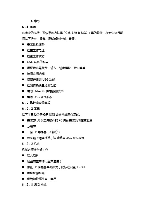
6 命令6.1 概述此命令的执行主要依靠的方法是PC和安装有USG工具的软件,在命令执行期间以下检查、调节、测试都被控制、管理。
⏹安装检验设备⏹检查工作电压⏹检查工作状态⏹USG系统的配臵⏹调整传感器参数、输入、输出模块、接口等等⏹检测监测功能⏹调整并设定USG功能⏹检测棉条质量检测功能⏹填写Uster FP传感器测试书⏹填写USG命令形态6.2 执行命令的要求6.2.1工具以下工具和仪器都是USG命令系统所必需的。
⏹安装带USG工具软件的PC具体安装说明在第五章⏹万用表⏹一套FP导棉器(3部分)⏹导条器上螺丝扳手,该扳手有USG系统提供6.2.2机械机械必须准备好工作⏹喂入原料⏹调整前主牵伸(生产速度)⏹修正FP传感器牵伸张力,比标准设臵1~3%⏹调整牵伸距离⏹供给初级插头座主电压6.2.3 USG系统⏹USG系统的装配和接线按照第五章所介绍的完成⏹接通PC电源和用标准电缆与USG PC 联接②联接⏹选择右COM接12⏹USG工具是可用的在打开机器带有提供24VDC开关的主开关之前必须切断与AS组件的连接6.3 安装检查6.3.1 准备⏹机器主开关断开⏹J1B插座与AS组件断开6.3.2 安装检查设备以下USG功能部分⏹机器状态(USG 部件)⏹操作终端⏹输入、输出模块⏹报警灯⏹FP传感器带前臵放大器的测量单元、喷嘴、PVC管、LEMO插头、黄色警告标志‚精密传感器示警‛⏹产量传感器安装并且调整与圆盘发信装臵的距离⏹清洁装臵⏹空气过滤器/控制装臵⏹压力控制的暂时压力位于正确的控制压力3bar⏹PC插头座⏹电线、带线箍管、电线正确固定⏹正确安装和接线,MS90、BAS、TEX组件于USG设备上。
6.3.3 接线接线必须根据第五章图表检查,特别是检查以下连接。
⏹供24VDC的初的初、次级开关⏹在AS组件中24VDC提供接插件J113/1(+24V)和J1。
B/2(木)注意极性⏹24VDC提供输入,输出原件⏹操作终端电压13VDC⏹输入、输出原件电压13VDC⏹FP传感器电压±12V⏹在MS 90 BAS。
电气设备说明说明书

Arc-resistant metal-clad switchgear is built to resist the effects of arcing faults occurring inside the switchgear assembly. An arcing fault produces a variety of physical phenomena, including sudden pressure increases and extreme localized overheating, which combine to destroy conductors, insulation, and enclosure parts. Internal arcing faults result in severe mechanical and thermal stresses on the switchgear assembly, and the materials involved in the arcing fault may produce hot decomposition products, either gaseous or particulate. A plenumand exit duct vents direct this away from personnelto a designated area.Arc-resistant switchgear making safety more comfortableThe NEC T calls for an arc flash boundary of zero around medium voltage switchgearif it has been successfully certified as arc-resistant switchgear per IEEE T C37.20.7. With certified Type 2B arc- resistant switchgear, arc flash boundaries are eliminated even when the control compartment doors are open (for Eaton switchgear, this includes the control compartment doorin front of the circuit breaker). Eaton offers a wide varietyof tested two-high switchgear configurations and bus transitions certified by UL T to protect personnel from arcing faults of up to 63,000A rms for a duration of 0.5 seconds. Type 2B ratings are available for all arc-resistant configura-tions, reducing required personal protective equipment even with control doors open.Protection from the harmfuleffects of arcing faultsFully tested system configurations (layout flexibility)• 36-inch-wide vertical structures• Two-high breaker configurations• Two-high configurations with auxiliary drawer,fuse drawer, and circuit breaker combinations• The ability to mount devices on circuit breaker doors helps to minimize equipment size for two-high configurations • Ability to mount protective relays, meters and other controls on each of the three compartment doors allows for more compact switchgear designs• Direct roll-in circuit breakers available in both upper and lower breaker compartments • Tested standard bus duct connections available upon request• Close coupling with medium voltage MCCs, transformers and other equipment tested to IEEE C37.20.7• Metal-clad switchgear close coupled to medium voltage motor control sharing a single arc exhaust plenum and ducting system Rugged arc-resistant construction• Structure is built to withstand the effects of internal faults up to the maximum fault current rating of the switchgear• Formed steel compartment design provides sealed joints under fault conditions• Includes extra-strength, multi-point latches and robust door hinges to ensure that doors remain intact and latched during an arcing event• A welded heavy-dutydoor design safely contains the extreme forces ofan arcing faultIntegral safety features• Metal-clad construction certified to IEEE C37.20.2 provides maximum circuit separation and safety• Type 2B arc-resistant construction allows for all instrument compartment doors to be opened without sacrificing protection from a potential internal arcing fault • Door interlocks ensure that the breaker door remains closed unless the breakeris open and racked out• Through-the-door racking is provided to rack circuit breakers in or out without opening the arc-resistant circuit breaker doorSafety enhancement options • Optional universal power racking device allows an operator to rack a breakerin from a distance• Optional integral remote racking device allows racking of circuit breaker without the hassle of moving, connecting, and storing a large device• Lifting pan available to lift circuit breakers from belowProtection and metering• Eaton will incorporate any manufacturer’s microprocessor- based protective relays, including Eaton’s full line of protective relays featuringour patented Arc Reduction Maintenance System E• Eaton will incorporateany manufacturer’s meters, including Eaton’s Power Xpert T power quality meter, which detect sags, swells and harmonics in addition to comprehensive power measurements and logging • Zone selective interlocking can be supplied upon request otee:N For comprehensive application information switchgear controls, please see Eaton’s Consulting Application Guide (Section 5).Arc-resistant standards Eaton’s arc-resistant switchgear has been fully tested in accordance with ANSI C37.20.7 (Type 2B).Metal-clad switchgear standardsANSI / IEEE C37.20.2Seismic qualificationSeismic-qualified by actual testing to meet requirements of IBC 2006 and CBC 2007.Ratings• Rated max voltage:5 kV–15 kV• Maximum short-circuit rating:Up to 63 kA (5/15 kV Class)• BIL rating: 60 kV for 5 kVClass, 95 kV for 15 kV Class• Main bus ratings: 1200A,2000A, 3000A, 4000A• 40 kA arc-resistant ratingsare available for 27 kV and38 kV class equipment withcontinuous current ratingsup to 3000Aotee:N4000A ratingrequires fan cooling.Many configurations areavailable to create the perfectsystem to meet your needs.Refer to Eaton’s ConsultingApplications Guide for completedetails of available ratings andlayout dimensions.Exhaust ducts can exit from front, side or rear. Two duct exits arerequired for switchgear rated 50 kA and higher. Contact factorywith specific application questions.Eaton CorporationElectrical Sector1111 Superior Ave.Cleveland, OH 44114United States877-ETN-CARE (877-386-2273)© 2011 Eaton CorporationAll Rights ReservedPrinted in USAPublication No. PA02200002E / Z10595April 2011Eaton is a registered trademarkof Eaton Corporation.All other trademarks are propertyof their respective owners.。
电气产品说明书

Eaton 260089Eaton Moeller® series CI Insulated enclosure, IP55_x, rotary handle black grey, for PKZ0 CI-PKZ0-GMGeneral specificationsEaton Moeller® series CI Insulated enclosure2600894015082600891126 mm 158 mm 80 mm 0.2 kg CECI-PKZ0-GMProduct NameCatalog Number EANProduct Length/Depth Product Height Product Width Product Weight Compliances Model CodePlasticBlack-gray rotary knobPE(N) terminal2 x M20 (cable entry knockouts at the rear)Hard mirror with cable entry knockouts (can be cut out) 2 x M25 (cable entry knockout with thread at the top)2 x M25 (cable entry knockout with thread at the bottom)IP55NEMA OtherSurface mountingAccessories+L-PKZ0 (2 units), +NHI or U or A, PKZM0-…-25 °C70 °C0 W10 W0 W0 A0 WMeets the product standard's requirements. Meets the product standard's requirements. Meets the product standard's requirements.Brochure - CI-K small enclosuresUKCA CI..-PKZ.. Surface mounted enclosures and accessories PKZ CE CI..-PKZ.. Surface mounted enclosures and accessories PKZeaton-manual-motor-starters-mounting-ci-insulated-enclosure-dimensions-002.epseaton-manual-motor-starters-enclosure-ci-insulated-enclosure-dimensions.epseaton-manual-motor-starters-enclosure-ci-k-accessory-dimensions-002.epseaton-manual-motor-starters-enclosure-ci-insulated-enclosure-3d-drawing-003.epsDA-CE-ETN.CI-PKZ0-GMIL03407019ZEnclosure material Fitted with: Knockouts Degree of protectionModelProduct categoryUsed withAmbient operating temperature - min Ambient operating temperature - maxEquipment heat dissipation, current-dependent PvidHeat dissipation capacity PdissHeat dissipation per pole, current-dependent PvidRated operational current for specified heat dissipation (In) Static heat dissipation, non-current-dependent Pvs10.2.2 Corrosion resistance10.2.3.1 Verification of thermal stability of enclosures10.2.3.2 Verification of resistance of insulating materials to normal heat Brochures Compliance information DrawingseCAD model Installation instructionsMeets the product standard's requirements.Please enquireDoes not apply, since the entire switchgear needs to be evaluated.Does not apply, since the entire switchgear needs to be evaluated.Meets the product standard's requirements.Does not apply, since the entire switchgear needs to be evaluated.Meets the product standard's requirements.Does not apply, since the entire switchgear needs to be evaluated.Does not apply, since the entire switchgear needs to be evaluated.Is the panel builder's responsibility.Is the panel builder's responsibility.Is the panel builder's responsibility.Is the panel builder's responsibility.Is the panel builder's responsibility.The panel builder is responsible for the temperature rise calculation. Eaton will provide heat dissipation data for the devices.DA-CS-ci_pkz0_gm DA-CD-ci_pkz0_gm10.2.3.3 Resist. of insul. mat. to abnormal heat/fire by internalelect. effects10.2.4 Resistance to ultra-violet (UV) radiation10.2.5 Lifting10.2.6 Mechanical impact10.2.7 Inscriptions10.3 Degree of protection of assemblies10.4 Clearances and creepage distances10.5 Protection against electric shock10.6 Incorporation of switching devices and components10.7 Internal electrical circuits and connections10.8 Connections for external conductors10.9.2 Power-frequency electric strength10.9.3 Impulse withstand voltage10.9.4 Testing of enclosures made of insulating material10.10 Temperature rise10.11 Short-circuit ratingmCAD modelEaton Corporation plc Eaton House30 Pembroke Road Dublin 4, Ireland © 2023 Eaton. All rights reserved. Eaton is a registered trademark.All other trademarks areproperty of their respectiveowners./socialmediaIs the panel builder's responsibility. The specifications for the switchgear must be observed.Is the panel builder's responsibility. The specifications for the switchgear must be observed.The device meets the requirements, provided the information in the instruction leaflet (IL) is observed.10.12 Electromagnetic compatibility10.13 Mechanical function。
电气设备产品说明书

Eaton 189894Eaton Moeller® series PKZM0 Motor-protective circuit-breaker, 3p, Ir=0.1-0.16A, screw connectionGeneral specificationsEaton Moeller® series PKZM0 Motor-protective circuit-breaker189894PKZM0-0,16-EA401508187890176 mm 93 mm 45 mm 0.243 kgCE Marked RoHS conformProduct NameCatalog Number Model Code EANProduct Length/Depth Product Height Product Width Product Weight Compliances0 kW0.1 A150 kA150 kA150 kA150 kA5.39 W2.5 A0.16 ATurn button150 kAIP20Thermomagnetic2.5 A0 kWBuilt-in device fixed built-in technique Phase failure sensitive Save time and space thanks to the new link module PKZM0-XDM32ME Motor Starters in System xStart - brochureProduct Range Catalog Switching and protecting motorsSwitching and protecting motors - catalogeaton-manual-motor-starters-characteristic-characteristic-curve-009.eps eaton-manual-motor-starters-characteristic-characteristic-curve-008.eps eaton-manual-motor-starters-characteristic-characteristic-curve.epsDA-DC-00004890.pdfeaton-manual-motor-starters-pkz-dimensions.epseaton-manual-motor-starters-pkz-dimensions-002.epseaton-manual-motor-starters-pkz-dimensions-003.epseaton-manual-motor-starters-pkzm0-3d-drawing-008.epseaton-manual-motor-starters-mounting-3d-drawing-002.epseaton-general-ie-ready-dilm-contactor-standards.epseaton-manual-motor-starters-circuit-breaker-pkzm0-3d-drawing.epsDA-CE-ETN.PKZM0-0,16-EAIL034046ZUWIN-WIN with push-in technologyDA-CS-pkzm0DA-CD-pkzm0eaton-manual-motor-starters-transformer-pkzm0-wiring-diagram.epsRated operational power at AC-3, 380/400 V, 50 Hz Overload release current setting - minRated short-circuit breaking capacity Ics at 400 V AC Rated short-circuit breaking capacity Icu at 440 V AC Rated short-circuit breaking capacity Ics at 440 V AC Rated short-circuit breaking capacity Icu at 400 V AC Power lossAdjustment range undelayed short-circuit release - max Overload release current setting - maxActuator typeRated short-circuit breaking capacity Ics at 500 V AC Degree of protectionSwitch off techniqueAdjustment range undelayed short-circuit release - min Rated operational power at AC-3, 220/230 V, 50 Hz Device constructionFunctionsElectrical connection type of main circuit BrochuresCatalogsCharacteristic curveDeclarations of conformity DrawingseCAD modelInstallation instructions Installation videosmCAD modelWiring diagramsEaton Corporation plc Eaton House30 Pembroke Road Dublin 4, Ireland © 2023 Eaton. All Rights Reserved. Eaton is a registered trademark.All other trademarks areproperty of their respectiveowners./socialmediaScrew connection150 kAThree-pole690 V150 kA0.16 A150 kA690 VRated short-circuit breaking capacity Icu at 500 V AC Number of poles Rated operational voltage (Ue) - min Rated short-circuit breaking capacity Icu at 690 V AC Rated uninterrupted current (Iu)Rated short-circuit breaking capacity Ics at 690 V AC Rated operational voltage (Ue) - max。
DW01产品说明书中文版

单位 V V V
mW ℃ ℃
最大绝对额定值是极限值,在任何情况下都不能片刻超过。而且,任两项不能同时达到此 值。在最大绝对额定值以上工作会引起器件特性衰退或者永久损坏。这里仅强调额定值,并不 表示在额定值下实际的工作情况。
七、电气特性
符号 VDD1
VDET1
VREL1 tVDET1 VDET2 VREL2 tVDET2 VDET3 tVDET3 Vshort tshort
5
DW 01
十、封装尺寸(单位:毫米)
SOT-23-6
锂电池保护 IC
6
静态电流 待机电流
条件
VDD 到 VSS 之间的电压
检测电源电 压的上升沿
温度 25℃ 0~50℃ *Note
VDD=3.6V to 4.4V 检测电源电压的下降沿
VDD=3.6V to 2.2V 检测“V-”pin 电压的上升沿
VDD=3.0V VDD=3.9V VDD=3.0V VDD=4.4V Iol=50uA,VDD=3.9V Iol=-50uA, VDD=2.2V Iol=50uA,VDD=3.9V VDD=3.9V, V-=0V VDD=2.0V
当有外部短路电流时,短路保护电路会立即使Dout变为低电位,当外部短路电流消失后, Dout 会转换为高电位。在检测到过放之后,IC 会通过关闭一些内部电路使电源电流非常低。 过充检测电路的延迟时间可以通过连接外部电容进行设置。Cout Pin 和Dout Pin的输出类型 是CMOS。封装形式为SOT23-6。
最小值 1.5 4.25 4.24 4.05 80 2.30 2.90 22 0.12 5 1.20
3.4
3.4
典型值
4.30
- 1、下载文档前请自行甄别文档内容的完整性,平台不提供额外的编辑、内容补充、找答案等附加服务。
- 2、"仅部分预览"的文档,不可在线预览部分如存在完整性等问题,可反馈申请退款(可完整预览的文档不适用该条件!)。
- 3、如文档侵犯您的权益,请联系客服反馈,我们会尽快为您处理(人工客服工作时间:9:00-18:30)。
3.3、本船设6-Q-A—195照明蓄电池四只(一组),供全船DC24V用电。
3.4、设AJ50—30/2 AC220V20A岸电箱一只,借船舶停靠码头接岸电用。配漏电保护器。
7、航行、信号灯
7.1、航行、信号灯由二路DC24V电源供电,一路来自主配电板经AC220V/DC24V电源装置后向其供电;另一路来自充放电板。航行、信号灯控制箱设于驾控台上。
7.2、配后白桅灯、红绿舷灯各1只、白尾灯1只、红环照灯2只白绿环照灯各1只。红绿白闪光灯各1只,锚灯一只。
8生活用电设备
8.1、本船员休息室、驾驶室配设AC220V插座供空调之用。
10.2、控制台还设有航行信号灯、闪光灯控制与指示灯,机舱监测报警的总灯复示。
11、电缆与其它
11.1、本船一般电缆为CEF/DA型、动力与易受机械操作处选用CEF90/DA型,接岸电缆为CEFR/DA型。
11.2、配电箱柜及驾控台内部接线为CBVR型。
11.3、全船电缆敷设依据ZB/TU06002-89“船舶电缆敷设工艺”的有关要求而进行。
8.2、本船配设电饭煲电水壶各一只。
8.3、卫生间设洗衣机一台。
8.4、设540mm(21英寸)彩电及全方位天线一套。
9、广播、通信、助航报警设备
9.1、本船配设MBS(CKY-1/C)型50W扩音机一台,配60 25W高音喇叭两只,借对外喊话用。
9.2、在机舱与驾驶室、船艉甲板与驾驶室设有电铃或鸣音信号Βιβλιοθήκη 统,作相互通信联络用。2、电制
2.1、本船生活用电、部分照明用电为AC220V为单相线双线绝缘制。
2.2、广播通信、部分照明用电为直流24V为双线直流绝缘配电制。
2.3、、报警等直流用电为DC24V双线制,电起动回路允许负极接地。
3、电源
3.1、本船设STC-15、230V、50HZ、15kW发电机一台(由L28M系列柴油机驱动),借全船动力照明通导设备、生活用电及充电之用。
47.70m货船
标记
数量
修改单号
签字
日期
电气说明书
ZHC423-601-01SM
编制
张光标
校对
韩婷
审核
总面积
0.18m2
共4页
第1页
标检
枣庄市鸿泰船舶技术服务部
审定
47.70m货船电气说明书
ZHC423-601-01SM
第2页
1、总则
本船的电气部分按《钢质内河船舶入级与建造规范》(2002)的要求进行设计;满足《内河船舶法定检验技术规则》(2004)和《修改通报》的有关要求;
卫生间设有遥控按钮盒。
6.3、机舱主要采用CCD4DC24V 40W低压舱顶灯。
6.4、厨房、浴室、厕所、外走道等处采用CCD4型DC24V 40W低压顶灯和CCD5DC24V 25W型低压舱顶灯。
47.70m货船电气说明书
ZHC423-601-01SM
第3页
6.5、船员室、驾驶室采用CCD4DC24V 40W低压舱顶灯,每个床位设24床头灯一只,每一写字台配台灯一只。
9.7、无线电分电箱由主电源和备用电源两路供电,备用电源为蓄电池组,驾控台内设有相应的充电装置。
47.70m货船电气说明书
ZHC423-601-01SM
第4页
10、驾驶室控制台
10.1、驾驶室设有控制台一座,舵操作、主机遥控、传令钟、甚高频电话、导航雷达及舵角批示、主机转速表、探照灯、搜索灯的控制等。
11.4、全船电气设备的安装依据ZB/TU06003-89“船舶电气设备安装工艺”的有关要求而进行。
9.3、配CQT-130磁罗经一套。
9.4、主机遥控选用KE-4a型(DC24V)电控遥控装置,配KED11-F2-G/Q双机型传令钟装置一套。
9.5、主机监测报警由随配四保护装置完成,机舱另配报警箱(BJ-8),主要对辅机的油水、齿轮箱的滑油失压、舵机过载与失电进行监测报警。
9.6、本船配有IC-M59甚高频电话及电源、天线系统二套。另配手持式甚高频电话(FB128)二只。
4、配电设备
4.1、本船设主配电板一座,板上设有监测发电机电压、频率功率、电流的F72系列电表。
4.2、主配主开关、负载开关选用为C65N系列。
4.3、设充放电板一只,向电瓶组提供浮充控制,其充电电源可由硅整流发电机提供,也可由15kW发电机或岸电经变压后提供。
5、电力设备
5.1、设电动粉碎泵一台,AC220V 1.6KW由机旁磁力启动器控制
