ABB ACS880传动系统培训
ABB变频器ACS880系列制动单元原理及故障解析
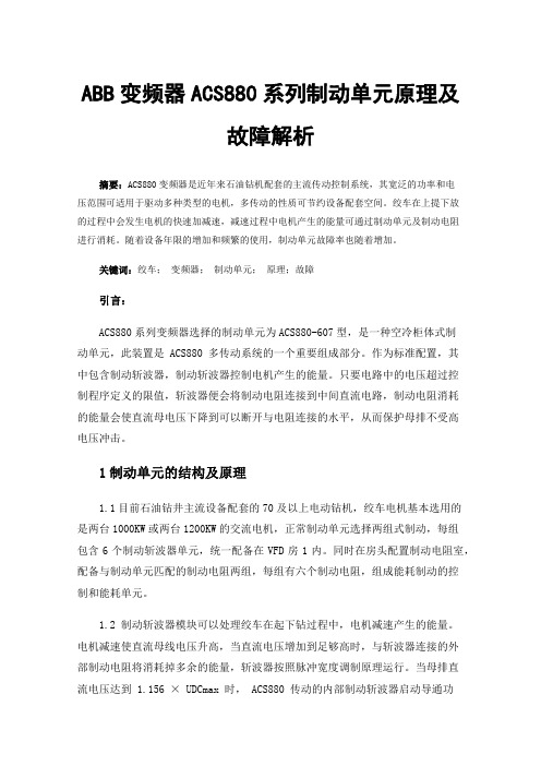
ABB变频器ACS880系列制动单元原理及故障解析摘要:ACS880变频器是近年来石油钻机配套的主流传动控制系统,其宽泛的功率和电压范围可适用于驱动多种类型的电机,多传动的性质可节约设备配套空间。
绞车在上提下放的过程中会发生电机的快速加减速,减速过程中电机产生的能量可通过制动单元及制动电阻进行消耗。
随着设备年限的增加和频繁的使用,制动单元故障率也随着增加。
关键词:绞车;变频器;制动单元;原理;故障引言:ACS880系列变频器选择的制动单元为ACS880-607型,是一种空冷柜体式制动单元,此装置是 ACS880 多传动系统的一个重要组成部分。
作为标准配置,其中包含制动斩波器,制动斩波器控制电机产生的能量。
只要电路中的电压超过控制程序定义的限值,斩波器便会将制动电阻连接到中间直流电路,制动电阻消耗的能量会使直流母电压下降到可以断开与电阻连接的水平,从而保护母排不受高电压冲击。
1制动单元的结构及原理1.1目前石油钻井主流设备配套的70及以上电动钻机,绞车电机基本选用的是两台1000KW或两台1200KW的交流电机,正常制动单元选择两组式制动,每组包含6个制动斩波器单元,统一配备在VFD房1内。
同时在房头配置制动电阻室,配备与制动单元匹配的制动电阻两组,每组有六个制动电阻,组成能耗制动的控制和能耗单元。
1.2 制动斩波器模块可以处理绞车在起下钻过程中,电机减速产生的能量。
电机减速使直流母线电压升高,当直流电压增加到足够高时,与斩波器连接的外部制动电阻将消耗掉多余的能量,斩波器按照脉冲宽度调制原理运行。
当母排直流电压达到1.156 × UDCmax 时, ACS880 传动的内部制动斩波器启动导通功能,制动电阻开始消耗电能;当母排直流电压达到 1.2 × UDCmax 时,制动达到 100% 脉冲宽度。
1.3 制动斩波器单元包括与直流母排相连接的直流熔断器、制动斩波器模块NBRA、制动斩波器冷却风机及制动控制附件等。
G380ACS880-01操作启动及基本维护
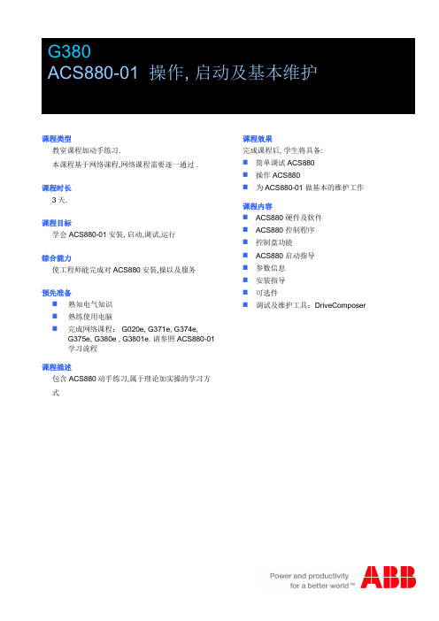
课程类型教室课程加动手练习.本课程基于网络课程,网络课程需要逐一通过 .课程时长3天.课程目标学会ACS880-01安装,启动,调试,运行综合能力使工程师能完成对ACS880安装,操以及服务预先准备n熟知电气知识n熟练使用电脑n完成网络课程: G020e, G371e, G374e, G375e, G380e , G3801e.请参照ACS880-01学习流程课程描述包含ACS880动手练习,属于理论加实操的学习方式课程效果完成课程后,学生将具备:n简单调试ACS880n操作 ACS880n为ACS880-01做基本的维护工作课程内容n ACS880硬件及软件n ACS880控制程序n控制盘功能n ACS880启动指导n参数信息n安装指导n可选件n调试及维护工具:DriveComposerG384ACS880-04/04XT和-07操作,启动和基本维护课程类型和描述ACS880操作,启动和基本维护课程包括两部分:网络课程和教室课程.这是本课程的第二部分:在老师指导下,带有设备操作的教室课程。
本课程包括ACS880动手练习本课程第一部分是包括理论知识的网络课程。
教室课程不包含网络课程内容。
在教室课程之前,你必须完成相应的网络课程,这样你才能够在教室中顺利完成动手练习。
我们可以查看网络课程完成情况。
请参考相关的学习途径预备知识n电气基本知识n课程G380n网络课程G3804e, G3847e and G3841e.对于ACS880课程内容和时间长度请参考ACS880学习程式课程时长课程时间1天学员要求本次课程针对ACS880-04和ACS880-07 维护,操作和服务的人员,包括电工,技术员,工程师课程目的本课程的目的是让学员能够维护,启动和操作ACS880传动课程目标完成本次课程,学员将能够:n ACS880-07传动调试n操作ACS880-07n对ACS880-04和ACS880-07进行基本维护主要内容n ACS880-04元器件查找和基本维护n ACS880-07元器件查找和基本维护n ACS880-07启动和操作n ACS880-07模块更换课程类型与描述ACS880多传动课程包括两部分:网络课程和教室课程这是本课程学习的第二部分:在老师指导下,带有设备操作的教室课程。
ACS880多传动柜及模块
2015 北京 ABB 电气传动系统有限公司
3AXD50000016089 版本 A 中文 3AUA0000102324 版本 A 英文 生效日期:2015-01-01
5
目录
1. 电气安装设计
本章内容 . . . . . . . . . . . . . . . . . . . . . . . . . . . . . . . . . . . . . . . . . . . . . . . . . . . . . . . . . . . . . . 7 本章规定所适用的产品 . . . . . . . . . . . . . . . . . . . . . . . . . . . . . . . . . . . . . . . . . . . . . . . . . . . 7 电源切断装置 (切断方式)的选择 . . . . . . . . . . . . . . . . . . . . . . . . . . . . . . . . . . . . . . . . . . 7 主接触器选型及尺寸设计 . . . . . . . . . . . . . . . . . . . . . . . . . . . . . . . . . . . . . . . . . . . . . . . . . . 8 传动的电源变压器配有一个 IGBT 供电装置或晶闸管供电装置。 . . . . . . . . . . . . . . . . . . . . . . . . . . . . . . . . . . . . . . . . . . . . . . 8 检查传动与电机的兼容性 . . . . . . . . . . . . . . . . . . . . . . . . . . . . . . . . . . . . . . . . . . . . . . . . . . 8
ACS880多传动的优势
ACS880多传动的优势
© ABB | Slide 1
ACS880多传动的优势
ACS880不可控二极管整流DXD
硬件成本降低,更具竞争力 柜体尺寸更小:ACS880 400mm or 700mm, ACS800 最小的DSU宽 1200mm
March © ABB
© ABB Group 29, 2016 | Slide 6
| Slide 6
ACS880多传动的优势 优异的电机控制性能
ACS800 现有的
• 卓越的 DTC 速度和转矩控制, 开闭环控制
ACS880 优势
• 基本控制程序 • 同一固件用于不同电机 (IM, PM, SynRM) 替代用于ACS800的标 准和系统控制程序 • 更快的给定(10ms变为2ms) • 支持高速电机频率可达500Hz(更高的 开关频率可能需要降容) • 支持绝对值编码器和旋转变压器
ACS800-104-0580-7, Icont.max=486A
ACS880-104-0600A-7,Icont.max=600A
电流+23%
© ABB | Slide 5
ACS880多传动的优势 单个R8i模块功率更大
单个逆变器功率更大,并联后选择更多。 用到的逆变器功率档更加细化,2xR8i分三档,3xR8i分两档,比原来 ACS800都多分出一档。 传动柜的总长度尺寸缩小。
© ABB | Slide 13
ACS880多传动的优势 DTC电机控制的性能
ACS880基本控制程序固件,一套固件同时支持多种电机,异步电机、永 磁同步电机、开关磁阻电机。取代了ACS800的标准固件和系统固件。 更快的给定链路。从10ms变为2ms 支持更高速的电机,最大可以到500Hz。 可以选择更高的开关频率,可以使电机的噪音更低。 除了继续支持增量型编码器以外,还支持绝对值编码器和旋转变压器作为 速度反馈。 轴承电流更低,对电机绝缘的冲击更小。启动力矩更加平滑,对于机械的 冲击也更小。 更加高效复杂的算法使得零速时的转矩特性更加优异
acs880操作面板使用手册
文章标题:深入理解ACS880操作面板使用手册1. 前言在工业控制领域,ABB的ACS880系列变频器因其卓越的性能和可靠的品质备受好评。
而ACS880操作面板作为变频器的主要控制界面,对于用户来说是非常重要的。
在本文中,我们将全面探讨ACS880操作面板的使用手册,帮助您更深入地了解并掌握这一关键设备。
2. 简介ACS880操作面板是ABB ACS880系列变频器的核心部件之一,它提供了直观的用户界面,方便用户实现对变频器的控制和监测。
在使用手册中,详细介绍了操作面板的各个功能、参数设置和操作步骤,帮助用户更好地使用和维护变频器。
3. 深度讲解3.1 初识ACS880操作面板让我们从ACS880操作面板的外观和基本功能开始,通过对其按钮、显示屏和指示灯的解释,帮助用户快速上手并了解其基本操作。
3.2 参数设置和调整在使用手册中,对ACS880操作面板的参数设置和调整进行了详细的介绍,包括各个参数的含义和影响,以及如何根据实际需求进行调整。
这些内容将帮助用户更好地理解变频器的工作原理和控制逻辑。
3.3 操作步骤和实例除了讲解操作面板的基本功能和参数设置外,使用手册还提供了丰富的操作步骤和实例,帮助用户解决常见问题和应对各种工作场景,从而更好地应用ACS880操作面板。
4. 总结通过本文的全面讲解,相信您已对ACS880操作面板的使用手册有了更深入的了解。
在日常工作中,合理、准确地使用操作面板将有助于您更好地控制和监测变频器的运行,提高工作效率和生产质量。
5. 个人观点作为ACS880操作面板的使用手册撰写者,我深知其在实际工程应用中的重要性。
我在撰写使用手册时,充分考虑了用户的实际需求和操作习惯,力求让每一步操作都清晰明了,方便用户上手使用。
在文章的撰写过程中,我尽量按照所提供的要求和主题文字进行论述,并在总结部分对整篇文章进行了回顾和概括,以确保提供了全面、深刻和灵活的观点和理解。
6. 结语ACS880操作面板的使用手册对于用户来说是非常重要的参考资料,通过本文的讲解,相信您已对其有了更深入的理解。
01 ACS880 product introduction
10 kg
15 kg
23 kg
40 kg
50 kg
80 kg
98 kg
© ©ABB ABB 集团 Group 2012 July 年 1, 07 2016 月31 |日 Slide | 幻灯片 9 9
指定型号标签
A C S
8
8
0
-
0
1 结构
0
2
A
4
-
5 电压
+
K
4
5
4
产品系列
尺寸
可选项
© ©ABB ABB 集团 Group 2012 July 年 1, 07 2016 月31 |日 Slide | 幻灯片 10 10
55kW (75hp)
5.5kW (7.5hp)
525 - 690V * (+10/-15%)
© © ABB ABB集团 Group 2012 July 1, 年07 2016 月31 | Slide 日 | 幻灯片 8 8
250kW (350hp)
尺寸与重量
955 mm
405 mm
6 kg
8 kg
© ABB 集团 Group July 2012 1, 年2016 07月31 | Slide 日 | 幻灯片 2 2
整个传动组合全面兼容体系结构 学习一次,随处可用
相同的控制面板 • 简单的导航与监控 • 统一参数 • 内置USB接口,连接到计算机工 具
相同的计算机工具 • 快速统一的传动设置 • 灵活的监控能力 • 轻点鼠标,诊断支持
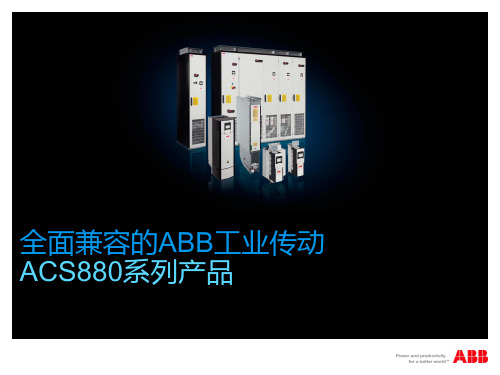
全面兼容的ABB工业传动 ACS880系列产品
全面兼容的ACS880工业传动 提高生产力和应用控制
ABB ACS880传动基本控制程序 快速启动指导
中文. . . . . . . . . . .3 English . . . . . . .13CN EN快速启动指导ACS880 传动基本控制程序相关手册信息您可以在网上查找并下载产品手册的PDF 文件。
参见封底背面的 Internet 上的文件库。
Document library 里查找不到的手册,请联系当地 ABB 代表。
传动硬件手册代码ACS880-01 传动硬件手册3AUA0000078093ACS880-07 传动 (45 至 250 kW, 60至 300 hp) 硬件手册3AUA0000105718ACS880-104 逆变模块硬件手册3AUA0000104271ACS880-107 逆变单元硬件手册3AUA0000102519传动固件手册和指导ACS880 基础控制程序固件手册3AUA0000085967ACS880 传动基础控制程序,快速启动指导3AUA0000098062可选件手册和指导ACS-AP-x 助手控制盘用户手册3AUA0000085685传动编辑器启动和维护PC 工具用户手册3AUA0000094606I/O 扩展模块,现场总线适配器,编码器接口等手册和快速启动指导ACS880-01 手册ACS880-07 手册3ABD0000098062 版本 A 中文/英文生效日期: 2013-09-012013 北京ABB 电气传动系统有限公司版权所有ACS880 基本控制程序快速 启动指导 3IT NL RU SVACS880 基本控制程序快速 启动指导关于本指导本指导介绍了配备基本控制程序的ACS880传动的基本启动顺序。
可以从固件手册 中找到传动固件的完整介绍。
(请参见封皮内页的手册列表)。
在本指导中,使用 ACS-AP-I 控制盘对传动进行设置。
该启动顺序也同样可以通过Drive composer PC tool 来实现。
在您启动之前确保传动已经如快速安装指导 和/或 硬件手册 上的描述进行正确的机械和电气安装。
ABB PLC AC800M培训中文教程

目录•PLC基础知识•ABB PLC AC800M硬件系统•软件安装与配置•基本编程技能•高级编程技能•系统维护与优化PLC基础知识PLC定义及发展历程PLC定义可编程逻辑控制器(Programmable Logic Controller,PLC)是一种数字运算操作的电子系统,专为在工业环境下应用而设计。
发展历程从1960年代末期的初创阶段,到1970年代中期的成熟阶段,再到1980年代以后的高速发展阶段,PLC 技术不断革新,功能日益强大。
PLC基本组成与工作原理基本组成PLC主要由中央处理单元(CPU)、存储器、输入输出接口、电源等部分组成。
工作原理PLC采用循环扫描的工作方式,即按照用户程序的顺序,逐条执行指令,完成各种控制任务。
PLC编程语言及标准编程语言PLC的编程语言主要有梯形图(LD)、指令表(IL)、功能块图(FBD)、顺序功能图(SFC)和结构化文本(ST)五种。
标准国际电工委员会(IEC)制定了PLC编程语言的国际标准IEC 61131-3,规范了PLC编程语言的语法、语义和表达方式。
ABB PLC AC800M硬件系统AC800M控制器类型及特点AC800M控制器类型PM861、PM864、PM865等。
特点高性能、高可靠性、易于扩展和升级、支持多种通讯协议。
I/O模块类型与配置方法I/O模块类型数字量输入模块、数字量输出模块、模拟量输入模块、模拟量输出模块等。
配置方法通过Controller Builder软件进行配置,包括选择模块类型、设置模块参数、分配地址等。
通讯接口及网络拓扑结构通讯接口以太网接口、Profibus-DP接口、Modbus接口等。
网络拓扑结构支持星型、树型、环型等多种拓扑结构,可根据实际需求进行灵活配置。
软件安装与配置安装步骤下载ABB PLC AC800M软件安装包。
双击安装包,按照提示进行安装。
0203等待安装完成,重启计算机。
注意事项选择安装路径和组件,建议保持默认设置。
ABBPLCAC800M培训中文教程
ABBPLCAC800M培训中文教程AC800M拥有丰富的功能和特点,包括快速的处理速度、多任务处理能力、多种通信接口和支持多种编程语言等。
它支持多种编程语言,如结构化文本(ST)、连续函数图(CFC)、图表(FBD)等。
这些编程语言可以根据控制系统的需求进行选择和组合,灵活性高。
在ABBPLCAC800M培训中,学员将学习如何配置和编程AC800M控制器,以及如何使用AC800M系列软件工具进行编程和调试。
培训内容包括以下方面:1.AC800M硬件概述:学员将会了解AC800M控制器的硬件组成和工作原理。
了解各种模块的功能和特点,并学习如何进行硬件的配置和连接。
2.AC800M软件工具:学员将熟悉AC800M系列软件工具,包括工程建模工具、编程工具和调试工具等。
学习如何使用这些工具进行PLC程序的编写和调试。
3.编程语言:学员将掌握AC800M支持的多种编程语言,如ST、CFC、FBD等。
学习如何选择和组合这些编程语言,编写出高效、稳定的控制程序。
4.通信接口:学员将了解AC800M支持的各种通信接口,如以太网、串口、CAN总线等。
学习如何配置和使用这些通信接口,实现与其他设备的数据交换和通信。
5.系统集成:学员将学会如何将AC800M控制器集成到工业自动化系统中。
学习如何与其他设备进行数据交换和通信,实现整个系统的自动化控制。
培训的目标是使学员能够独立完成AC800M控制器的配置、编程和调试工作。
通过培训,学员将掌握AC800M控制器的核心技术,提高工作效率和自动化控制系统的可靠性。
总结来说,ABBPLCAC800M培训中文教程将系统地介绍AC800M控制器的硬件组成、软件工具、通信接口和编程语言等方面的知识。
学员将通过培训掌握AC800M控制器的配置、编程和调试技术,提高自己的工作能力和项目管理能力。
ACS880-01 技术样本
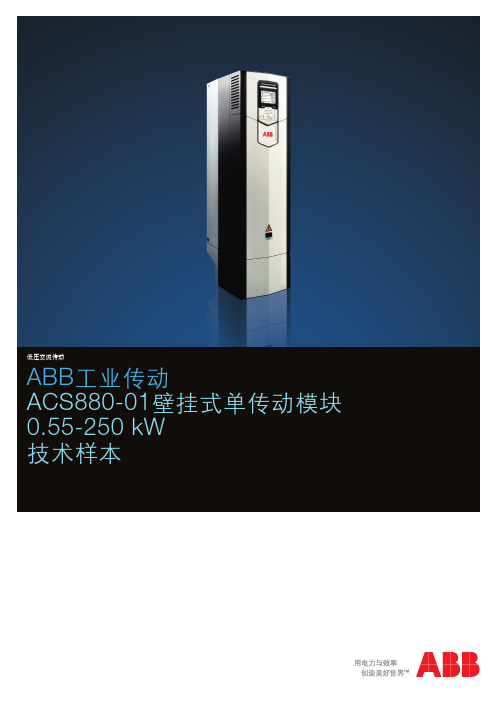
低压交流传动ABB 工业传动ACS880-01壁挂式单传动模块0.55-250 kW 技术样本低压交流传动2 ACS880-01壁挂式单传动模块 |低压交流传动创新驱动未来直接转矩控制(DTC )A B B 独一无二的电机控制术,矩控制。
传动到传动的连接可让变频器之间保持快速通讯——包括主从配置,无需任何额外的硬件。
可靠的安全性能安全力矩中断作为标配内置功能。
可选的安全功能模块可以提供扩展的安全功能,从而简化配置,减少安装空间。
可插拔式存储单元将所有软件和参数配置存储在方便更换、方便安装的存储单元中。
远程监控内置网络服务器NETA-21可让您在全球各地监控和访问传动模块。
能效管理该变频器可以提供诸如能源优化器和能效信息之类的功能,帮助您监控和节省工业过程的能耗量。
传动应用编程基于CODESYS 编程工具的客户定制化功能有助于满足特定的应用需求。
该传动还易于实现与ABB 的PLC 和HMI 等其他产品的打包集成方案。
低压交流传动 | ACS880-01壁挂式单传动模块3扩展的连接性除标准接口外,该变频器还有适用于其它输入/输出扩展模块和速度反馈接口的三个内置插槽。
直观的控制盘直观、高对比度、高分辨率的显示器,可让您轻松选择包括中文在内的多种语言。
可实现与所有主要自动化网络通讯现场总线通讯适配器支持与所有主要自动化网络建立连接。
灵活的产品配置变频器可以同时订购各种可选项,包括EMC 滤波器、制动可选项及不同的防护等级。
启动和维护工具PC 工具适用于变频器启动、配置及日常运行和工业过程调试。
该PC 工具通过以太网或USB 接口连接至变频器。
4 ACS880-01壁挂式单传动模块 |低压交流传动壁挂式单传动模块ACS880-01我们的壁挂式传动产品是在ABB 通用的传动架构上设计的。
它们为满足各个行业的确切需求量身定制,包括石油天然气、采矿、冶金、化工、水泥、发电厂、物料搬运、制浆造纸、木材加工和船舶等等。
ACS880多传动柜及模块

电气设计说明 ACS880 多传动柜及模块
相关手册清单
通用手册 《ACS880 多传动柜及模块安全说明》 《ACS880 多传动柜及模块电气设计说明》
代码 (英文) 3AUA0000102301 3AUA0000102324
多传动模块手册 《ACS880 多传动模块机柜设计与安装说明》 《ACS880-104 逆变器模块硬件手册》 《ACS880-304 (+A003) 二极管供电模块硬件手册》 《ACS880-604 单相制动斩波器模块硬件手册》
永磁同步电机 . . . . . . . . . . . . . . . . . . . . . . . . . . . . . . . . . . . . . . . . . . . . . . . . . . . . . . . . . . 16 电力电缆选型 . . . . . . . . . . . . . . . . . . . . . . . . . . . . . . . . . . . . . . . . . . . . . . . . . . . . . . . . . . 17
3AUA0000101764 3AUA0000102519 3AUA0000102453 3AUA0000102559
固件手册及指南 《ACS880 主控制程序固件手册》 《ACS880 主控制程序快速启动指南》 《ACS880 二极管电源控制程序固件手册》
3AUA0000085967 3AUA0000098062 3AUA0000103295
电机层与轴承保护 . . . . . . . . . . . . . . . . . . . . . . . . . . . . . . . . . . . . . . . . . . . . . . . . . . . . . 9 要求表 . . . . . . . . . . . . . . . . . . . . . . . . . . . . . . . . . . . . . . . . . . . . . . . . . . . . . . . . . . 10
acs880变频器静态辨识和动态优化
acs880变频器静态辨识和动态优化ACS880变频器是一种先进的电力设备,可以用于控制电动机的转速和转矩。
静态辨识和动态优化是ACS880变频器的两个重要功能,可以帮助用户实现更高效、更稳定的运行。
静态辨识是指通过对系统进行一系列的试验和测试,得到系统的静态特性,如传递函数、频率响应等。
静态辨识的目的是了解系统的基本性质,为后续的控制和优化提供依据。
在ACS880变频器中,静态辨识可以通过设置不同的工作模式和参数,对系统进行测试,得到系统的静态特性。
静态辨识可以帮助用户了解系统的动态响应能力,选择合适的参数和工作模式,以达到最佳的性能和效果。
比如,通过静态辨识可以确定变频器的最大输出功率和转矩,以及在不同负载下的性能表现。
通过对这些参数的测试和分析,用户可以根据自己的需求选择合适的变频器型号和配置。
动态优化是指通过对系统的动态特性进行测试和分析,优化系统的控制策略和参数,以提高系统的性能和稳定性。
在ACS880变频器中,动态优化可以通过设置不同的控制参数和反馈环节,对系统进行测试和调整,以达到最佳的控制效果。
动态优化可以帮助用户解决系统运行过程中的问题,提高系统的响应速度和控制精度。
比如,通过动态优化可以调整变频器的速度环和电流环参数,以提高系统的响应速度和稳定性。
动态优化还可以通过分析系统的频率响应,优化控制器的带宽和相位裕度,以提高系统的稳定性和抗干扰能力。
静态辨识和动态优化是ACS880变频器的两个重要功能,可以帮助用户实现更高效、更稳定的运行。
通过静态辨识,用户可以了解系统的基本性质,选择合适的变频器型号和配置。
通过动态优化,用户可以优化系统的控制策略和参数,提高系统的性能和稳定性。
在使用ACS880变频器进行静态辨识和动态优化时,用户需要注意以下几点。
首先,要根据实际情况选择合适的测试方法和参数设置。
不同的系统和应用场景可能需要不同的测试方法和参数设置,用户应根据实际情况进行选择。
其次,要进行充分的试验和测试,获取准确的数据。
ABB ACS880多功能驱动柜架和模块的安全说明、电气规划说明、柜架设计和建造说明及控制单元硬件说
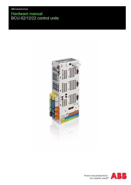
Hardware manualBCU-02/12/22 control unitsList of related manualsYou can find manuals and other product documents in PDF format on the Internet. See section Document library on the Internet on the inside of the back cover. For manuals not available in the Document library, contact your local ABB representative.General manualsCode (English)Safety instructions for ACS880 multidrive cabinets and modules3AUA0000102301Electrical planning instructions for ACS880 multidrive cabinets and modules3AUA0000102324Cabinet design and construction instructions for ACS880 multidrive modules3AUA0000107668BCU-02/12/22 control units hardware manual 3AUA0000113605Supply module manualsACS880-204 IGBT supply modules hardware manual 3AUA0000131525ACS880 IGBT supply control program firmware manual3AUA0000131562ACS880-304 +A018 diode supply modules hardware manual 3AXD50000010104ACS880 diode supply control program firmware manual3AUA0000103295ACS880-904 regenerative rectifier modules hardware manual 3AXD50000020457ACS880 regenerative rectifier control program firmware manual3AXD50000020827Inverter module manualsACS880-104 inverter modules hardware manual 3AUA0000104271ACS880 primary control program firmware manual 3AUA0000085967ACS880 primary control program quick start-up guide 3AUA0000098062Manuals for application programs (Crane, Winder, etc.)Brake module and DC/DC converter module manuals ACS880-604 3-phase brake chopper modules hardware manual3AXD50000022033ACS880 brake control program firmware manual (3-phase brake)3AXD50000020967ACS880-1604 DC/DC converter modules hardware manual 3AXD50000023642ACS880 DC/DC converter control program firmware manual 3AXD50000024671Module package hardware manualsACS880-04 module packages hardware manual3AUA0000138495ACS880-04XT drive modules (500 to 1200 kW) hardware manual3AXD50000025169ACS880-14 and -34 module packages hardware manual 3AXD50000022021Option manualsFSO-12 safety functions module user's manual3AXD50000015612FDPI-02 diagnostics and panel interface user’s manual3AUA00001136183AUA0000113605 Rev CENEFFECTIVE: 2015-05-292015 ABB Oy. All Rights Reserved.3 Table of contents1. BCU-02/12/22 control unitsContents of the manual . . . . . . . . . . . . . . . . . . . . . . . . . . . . . . . . . . . . . . . . . . . . . . . . . . . 5 Safety . . . . . . . . . . . . . . . . . . . . . . . . . . . . . . . . . . . . . . . . . . . . . . . . . . . . . . . . . . . . . . . . 5 Terms and abbreviations . . . . . . . . . . . . . . . . . . . . . . . . . . . . . . . . . . . . . . . . . . . . . . . . . . 5 Hardware description . . . . . . . . . . . . . . . . . . . . . . . . . . . . . . . . . . . . . . . . . . . . . . . . . . . . 6 Fiber optic connections . . . . . . . . . . . . . . . . . . . . . . . . . . . . . . . . . . . . . . . . . . . . . . . . . 7 Layout . . . . . . . . . . . . . . . . . . . . . . . . . . . . . . . . . . . . . . . . . . . . . . . . . . . . . . . . . . . . . . 7 The 7-segment display . . . . . . . . . . . . . . . . . . . . . . . . . . . . . . . . . . . . . . . . . . . . . . . . 11 Checking the delivery . . . . . . . . . . . . . . . . . . . . . . . . . . . . . . . . . . . . . . . . . . . . . . . . . . . 11 Identifying different control unit types . . . . . . . . . . . . . . . . . . . . . . . . . . . . . . . . . . . . . 11 Mechanical installation . . . . . . . . . . . . . . . . . . . . . . . . . . . . . . . . . . . . . . . . . . . . . . . . . . 12Installing the control unit . . . . . . . . . . . . . . . . . . . . . . . . . . . . . . . . . . . . . . . . . . . . . . . 13 Vertical DIN rail mounting . . . . . . . . . . . . . . . . . . . . . . . . . . . . . . . . . . . . . . . . . . . 13 Horizontal DIN rail mounting . . . . . . . . . . . . . . . . . . . . . . . . . . . . . . . . . . . . . . . . . 14 Installing the FSO-xx safety functions module . . . . . . . . . . . . . . . . . . . . . . . . . . . . . . 15 Electrical installation . . . . . . . . . . . . . . . . . . . . . . . . . . . . . . . . . . . . . . . . . . . . . . . . . . . . 16 Fault tracing . . . . . . . . . . . . . . . . . . . . . . . . . . . . . . . . . . . . . . . . . . . . . . . . . . . . . . . . . . 16 LEDs . . . . . . . . . . . . . . . . . . . . . . . . . . . . . . . . . . . . . . . . . . . . . . . . . . . . . . . . . . . . . . 16 Maintenance . . . . . . . . . . . . . . . . . . . . . . . . . . . . . . . . . . . . . . . . . . . . . . . . . . . . . . . . . . 17 Replacing the real-time clock battery . . . . . . . . . . . . . . . . . . . . . . . . . . . . . . . . . . . . . 17 Replacing the memory unit . . . . . . . . . . . . . . . . . . . . . . . . . . . . . . . . . . . . . . . . . . . . . 17 Replacing the SD/SDHC memory card . . . . . . . . . . . . . . . . . . . . . . . . . . . . . . . . . . . 17 Replacing the control unit . . . . . . . . . . . . . . . . . . . . . . . . . . . . . . . . . . . . . . . . . . . . . . 17 Replacement illustration . . . . . . . . . . . . . . . . . . . . . . . . . . . . . . . . . . . . . . . . . . . . . . . 18 Technical data . . . . . . . . . . . . . . . . . . . . . . . . . . . . . . . . . . . . . . . . . . . . . . . . . . . . . . . . . 19 Connector data . . . . . . . . . . . . . . . . . . . . . . . . . . . . . . . . . . . . . . . . . . . . . . . . . . . 19 Ground isolation diagram . . . . . . . . . . . . . . . . . . . . . . . . . . . . . . . . . . . . . . . . . . . . 21 Dimensions . . . . . . . . . . . . . . . . . . . . . . . . . . . . . . . . . . . . . . . . . . . . . . . . . . . . . . 22 Battery . . . . . . . . . . . . . . . . . . . . . . . . . . . . . . . . . . . . . . . . . . . . . . . . . . . . . . . . . . 22 Protection classes . . . . . . . . . . . . . . . . . . . . . . . . . . . . . . . . . . . . . . . . . . . . . . . . . 22 Ambient conditions . . . . . . . . . . . . . . . . . . . . . . . . . . . . . . . . . . . . . . . . . . . . . . . . . 22 Materials . . . . . . . . . . . . . . . . . . . . . . . . . . . . . . . . . . . . . . . . . . . . . . . . . . . . . . . . 22 Applicable standards . . . . . . . . . . . . . . . . . . . . . . . . . . . . . . . . . . . . . . . . . . . . . . . 22 Markings . . . . . . . . . . . . . . . . . . . . . . . . . . . . . . . . . . . . . . . . . . . . . . . . . . . . . . . . 22 Cyber security disclaimer . . . . . . . . . . . . . . . . . . . . . . . . . . . . . . . . . . . . . . . . . . . . . . . . 22 Dimension drawing . . . . . . . . . . . . . . . . . . . . . . . . . . . . . . . . . . . . . . . . . . . . . . . . . . . . . 23 Further informationProduct and service inquiries . . . . . . . . . . . . . . . . . . . . . . . . . . . . . . . . . . . . . . . . . . . . . 25 Product training . . . . . . . . . . . . . . . . . . . . . . . . . . . . . . . . . . . . . . . . . . . . . . . . . . . . . . . . 25 Providing feedback on ABB Drives manuals . . . . . . . . . . . . . . . . . . . . . . . . . . . . . . . . . . 25 Document library on the Internet . . . . . . . . . . . . . . . . . . . . . . . . . . . . . . . . . . . . . . . . . . . 254BCU-02/12/22 control units 5 BCU-02/12/22 control unitsContents of the manualThis manual contains a description of the use and structure of the control unit and its technical data. It also describes how to install and maintain the control unit.For safety information, see Safety instructions for ACS880 multidrive cabinets and modules (3AUA0000102301 [English]) or ACS880-04XT drive modules (500 to 1200 kW) hardware manual (3AXD50000025169 [English]).For information on the unit’s electrical installation, see Electrical planning instructions for ACS880 multidrive cabinets and modules (3AUA0000102324 [English]) and the appropriate drive/converter/inverter hardware manual or ACS880-04XT drive modules (500 to 1200 kW) hardware manual (3AXD50000025169 [English]).For information on the electrical installation of the FSO-xx safety functions module, see the FSO safety functions module user's manual.For the default I/O connection diagrams and more information on the connections, see the appropriate drive/converter/inverter hardware manual.For the related manuals, see List of related manuals.SafetyWARNING! Obey the safety instructions in Safety instructions for ACS880multidrive cabinets and modules (3AUA0000102301 [English]) or ACS880-04XTdrive modules (500 to 1200 kW) hardware manual (3AXD50000025169 [English]). If you ignore them, injury or death, or damage to the equipment can occur.Terms and abbreviationsLater in this manual, term converter substitutes for string drive/converter/inverter.6 BCU-02/12/22 control unitsHardware descriptionThe BCU-02, BCU-12 and BCU-22 are control units used for controlling converters via fiber optic links. It contains integrated branching unit functionality for collecting and storing real-time data from the converter modules to help fault tracing and analysis. The data is stored in a secure data card.The control unit types have a different number of fiber optic connections:BCU type No. of fiber optic connections Can be replaced withBCU-022BCU-02, BCU-12, BCU-22BCU-127BCU-12, BCU-22BCU-2212BCU-22You can use a BCU-22 to replace any of the control unit types.The control unit requires an external 24V DC power source. It has three option slots for I/O extensions, encoders and fieldbus adapters, an integrated Ethernet port for PC tool communication and a removable memory unit. For example, if the control unit needs to be replaced, the parameter settings can be retained by transferring the memory unit from the defective control unit to the new one.The control unit has an on-board data logger that collects real-time data from the converter power stages to help fault tracing and analysis. The data is stored onto the SDHC memory card inserted into the SD CARD slot and can be analyzed by ABB service personnel.The drive-to-drive link (XD2D) is a daisy-chained RS-485 transmission line that allows basic master/follower communication with one master and multiple followers. The control unit has also one option slot for connecting the RDCO DDCS communication option board. For more information, see the appropriate hardware manual.BCU-02/12/22 control units 7⏹Fiber optic connectionsThe BCU-02 control unit has two fiber optic connections V1and V2 for connecting to converter modules. The control unit does not include the BPEB-05 board. The BCU-12 control unit includes one BPEB-05 board that adds five connections to it (V3…V7), while the BCU-22 control unit includes two BPEB-05 boards and thus twelve connections (V1…V12).For instructions on connecting the control unit to the converter module, see theappropriate hardware manual .⏹LayoutThe following figures show the layout of the BCU-22 control unit. For the default I/O connection diagrams and more information on the connections, see the appropriate hardware manual.V1V2 V3V4 V5 V 6V7V8 V9 V10 V11 V12xINT Module 1xINT Module 3I/OBPEB-05BCU-x2BIOC-01BPEB-05xINT Module 2xINT Module 7xINT Module 8xINT Module 128 BCU-02/12/22 control units10 BCU-02/12/22 control unitsDescriptionI/O connectorXAI Analog inputXAO Analog outputXDI Digital input and digital start interlockXDIO Digital input/outputXD2D Drive-to-drive linkXD24+24 V output for digital inputXPOW External power inputXRO1Relay output 1XRO2Relay output 2XRO3Relay output 3XSTO Safe torque off connection (input signal).Note: This input only acts as a true Safe torque off input in control units controlling a motor.In other applications (such as a supply or brake unit), de-energizing the IN1 and/or IN2terminal will stop the unit but does not constitute a true safety function.For more information on Safe torque off, see the appropriate hardware manual.XSTO OUT Safe torque off connection (output for powering XSTO input of inverter modules).X485Not in useSwitchAI1Analog input 1 current/voltage selectionAI2Analog input 2 current/voltage selectionD2D TERM Drive-to-drive link terminationDICOM = DIOGND Determines whether DICOM is separated from DIOGND (ie, common reference for digital inputs floats).Fiber optic connectorV1T…V12T,V1R…V12RFiber optic connector to converter module: T = Transmitter, R = ReceiverConnector for optional moduleSLOT 1F-type adapter, interface and I/O extension modulesIf FDPI-02 diagnostics and panel interface is used, it has to be installed in slot 1 with twoscrews.SLOT 2F-type adapter, interface and I/O extension modulesSLOT 3F-type adapter, interface and I/O extension modules, FSO-xx safety functions module SLOT 4RDCO-0x DDCS communication option modulesSafety option connectorX12Cable connector for the FSO-xx safety functions module.Note: The FSO-xx safety functions module can be used only with ACS880 inverters.For more information on the FSO-xx safety functions module, see the FSO safety functionsmodule user's manual.Control panel and Ethernet connectorXETH Ethernet port for, eg, PC communicationX13Control panelMemory unit and card connectorX205MEMORYUNITConverter memory unit connectorSD CARD Secure digital card holder (Data logger memory for the fiber optic links)DescriptionMiscellaneous+ Battery Real-time clock battery⏹The 7-segment displayThe following table describes the indications of the 7-segment display on the control unit. Multicharacter indications are displayed as repeated sequences of characters.“U” is indicated shortly before “o”.The control program has been launched and is running.Flashing character.The firmware cannot be started: The memory unit is missing or corrupted.The firmware download from a PC to the control unit is in progress.At the converter power-up, the 7-segment display can show short indications of, for example,“1”, “2”, “b” or “U”. These are normal indications immediately after powering up the converter.If the 7-segment display ends up showing other values than described above after thepower-up, it indicates a hardware failure.Checking the deliveryCheck that all items listed below are present. Check that there are no signs of damage:•control unit with the I/O connectors•memory unit•SD/SDHC flash memory card (inserted in its slot)•real-time clock battery.⏹Identifying different control unit typesBefore installation, check that the control unit has the correct control program for the converter hardware in question. The control program is shown in the label attached to the memory unit.Check also that the control unit is suitable for your equipment configuration.Mechanical installationWARNING! Do not install the control unit in the immediate vicinity ofelectromagnetic disturbance sources, such as relays, contactors, brake choppers, power and motor cabling. The minimum recommended distance from such components is 200mm. We recommend to install metallic screening between the control unit and the source of disturbance. This can reduce the required distance.WARNING! Mount the control unit so that air can pass freely through theventilation holes in the housing. Avoid mounting directly above heat-generatingequipment.You can mount the control unit on a vertical or horizontal standard 35×7.5/15 mm DIN rail. In vertical direction, you can mount the unit either top or bottom upwards. When mounting the unit horizontally, the connectors must be downwards and the connector texts the right way up.Leave enough space for cabling, and replacing the memory unit and real-time clock battery. See sections Replacing the real-time clock battery, Replacing the memory unit and Replacing the SD/SDHC memory card on page 17.Installing the control unitThe control unit is grounded through the DIN rail.Vertical DIN rail mounting1.Fasten the latch to the back of the control unit with four screws.2.Click the control unit to the rail as shown below.3.Secure the control unit with an end bracket.Horizontal DIN rail mounting1.Fasten the latches to the back of the control unit with four screws.2.Click the control unit to the rail as shown below.Installing the FSO-xx safety functions module1.Fasten the FSO-xx safety functions module onto slot3 with four screws.2.Tighten the FSO-xx electronics grounding screw (0.8 N·m).3.Connect the FSO-xx data cable to FSO-xx connector X110 and to BCU-x2 connectorX12.For information on the electrical installation of the FSO-xx safety functions module, see the FSO safety functions module user's manual.Electrical installationWARNING! Obey the safety instructions given in Safety instructions for ACS880multidrive cabinets and modules [3AUA0000102301 (English)] or ACS880-04XTdrive modules (500 to 1200 kW) hardware manual (3AXD50000025169 [English]).If you ignore the safety instructions, injury or death can occur. If you are not aqualified electrician, do not do electrical work.Connect the +24V external power supply to the control unit connector XPOW.Connect the fiber optic cables and gate driver board wiring from the converter module to the control unit according to the instructions given in the converter module hardware manual.For general electrical installation instructions, see Electrical planning instructions for ACS880 multidrive cabinets and modules [3AUA0000102324 (English)] or ACS880-04XT drive modules (500 to 1200 kW) hardware manual (3AXD50000025169 [English]). Fault tracingLEDsLEDBATT OK When lit, the battery voltage of the real time clock is OK (higher than 2.8V).When off,•battery voltage is below 2.8V,•battery is missing, or•control unit is not powered.PWR OK When lit, internal voltage is OK.FAULT When lit, the control program indicates that the equipment is faulty. See the appropriate firmware manual.WRITE When lit, writing to the SD card is in progress.Maintenance⏹Replacing the real-time clock batteryReplace the real-time clock battery if the BATT LED is not illuminated when the control unit is powered. For information on the LED, see Fault tracing on page 16.See A in figure Replacement illustration on page 18.1.Undo the fastening screw and remove the battery. For the replacement battery type,see Real-time clock battery on page 22.2.Insert the new battery according to figure Replacement illustration.3.Dispose the old battery according to local disposal rules or applicable laws.4.Set the real-time clock.⏹Replacing the memory unitSee B in figure Replacement illustration on page 18.1.To remove the memory unit, undo the fastening screw and pull the memory unit out.See the following figure.2.Insert the new memory unit and fasten the screw.⏹Replacing the SD/SDHC memory cardNote: Do not remove the SD card while the yellow WRITE LED is lit. Writing to the SD card is in progress.See C in figure Replacement illustration on page 18.1.Undo the fastening screw of the clip covering the memory card and press the card toremove it. For the card location, see the following figure. For the replacement card type, see Ground isolation diagram on page 21.2.Insert the new card in reverse order.⏹Replacing the control unitSee section Installing the control unit on page 13.1.If the control unit has been installed vertically, remove the end bracket.2.Remove the control unit from the rail.3.Undo the four fastening screws with which the latch has been fastened to the back ofthe control unit.4.Pull out the detachable terminal blocks which have control cables connected.5.Install the new control unit in reverse order.Note: If there is a safety circuit connected to the STO terminals (XSTO) of the control unit, redo its acceptance test according to the instructions given in the inverter or drive module hardware manual.See the appropriate documentation: drive or inverter module hardware manual, safety option user’s manual and/or FSO safety functions module user’s manual.Replacement illustrationTechnical data Connector dataPower supply (XPOW)Connector pitch 5mm, wire size 2.5mm224V(±10%)DC, 2AExternal power input. Two supplies can be connected for redundancy.Relay outputs RO1…RO3 (XRO1…XRO3)Connector pitch 5 mm, wire size 2.5mm2 250V AC / 30V DC, 2AProtected by varistors+24 V output(XD24:2 and XD24:4)Connector pitch 5mm, wire size 2.5mm2Total load capacity of these outputs is 4.8W (200mA / 24V) minus the power taken by DIO1 and DIO2.Digital inputs DI1…DI6 (XDI:1…XDI:6)Connector pitch 5mm, wire size 2.5mm224V logic levels: “0”< 5V, “1”>15VR in: 2.0kohmInput type: NPN/PNP (DI1…DI5), NPN (DI6)Hardware filtering: 0.04ms, digital filtering up to 8msDI6 (XDI:6) can alternatively be used as an input for a PTC thermistor.“0” >4kohm, “1”<1.5kohmI max: 15mA (DI1…DI5), 5mA (DI6)Start interlock input DIIL (XDI:7)Connector pitch 5mm, wire size 2.5mm224V logic levels: “0”< 5V, “1” >15VR in: 2.0kohmInput type: NPN/PNPHardware filtering: 0.04ms, digital filtering up to 8 msDigital inputs/outputs DIO1 and DIO2(XDIO:1…XDIO:4)Input/output mode selection by parameters. DIO1 can be configured as a frequency input (0…16 kHz with hardware filtering of 4 microseconds) for 24 V level square wave signal (sinusoidal or other wave form cannot be used). DIO2 can be configured as a 24V level square wave frequency output. See the firmware manual.Connector pitch 5mm, wire size 2.5mm2As inputs:24V logic levels: “0” <5V, “1” >15VR in: 2.0kohmFiltering: 1msAs outputs:Total output current from +24VD is limited to 200mAReference voltage for analog inputs +VREF and -VREF(XAI:1 and XAI:2)Connector pitch 5mm, wire size 2.5mm210V ±1% and –10V ±1%, R load 1…10kohm Maximum output current: 10 mAR LDIOxDIOGND+24VDAnalog inputs AI1 and AI2 (XAI:4 … XAI:7).Current/voltage input mode selection by switches Connector pitch 5mm, wire size 2.5mm2Current input: –20…20mA, R in: 100ohmVoltage input: –10…10 V, R in > 200kohmDifferential inputs, common mode range ±30VSampling interval per channel: 0.25msHardware filtering: 0.25ms, adjustable digital filtering up to 8ms Resolution: 11 bit + sign bitInaccuracy: 1% of full scale rangeInaccuracy with Pt100 sensors: 10 °C (50 °F)Analog outputs AO1 and AO2(XAO)Connector pitch 5 mm, wire size 2.5mm2 0…20mA, R load < 500ohmFrequency range: 0…500Hz Resolution: 11 bit + sign bit Inaccuracy: 2% of full scale rangeDrive-to-drive link (XD2D)Connector pitch 5mm, wire size 2.5mm2 Physical layer: RS-485Termination by switchRS-485 connection (X485)Connector pitch 5mm, wire size 2.5mm2 Physical layer: RS-485Safe torque off connection (XSTO)Connector pitch 5mm, wire size 2.5mm2Input voltage range: -3…30V DCLogic levels: “0” < 5V, “1” >17VFor the unit to start, both connections must be “1”Current consumption: 66 mA (continuous) per STO channel per inverter moduleEMC (immunity) according to IEC61326-3-1Safe torque off output (XSTO OUT)Connector pitch 5mm, wire size 2.5mm2 To STO connector of inverter moduleControl panel connection (X13)Connector: RJ-45 Cable length < 3mEthernet connection(XETH)Connector: RJ-45SDHC memory card slot (SD CARD)Memory card type: SDHC Maximum memory size: 4GBThe terminals on the board fulfil the Protective Extra Low Voltage (PELV) requirements. The PELV requirements of a relay output are not fulfilled if a voltage higher than 48 V is connected to the relay output.BCU-02/12/22 control units 21 Ground isolation diagramXPOW+24VI1GND2+24VI3GND4XAI+VREF1-VREF2AGND3AI1+4AI1-5AI2+6AI2-7XAOAO11AGND2AO23AGND4XD2DB1A2BGND3SHIELD4XRO1, XRO2, XRO3NC11COM12NO13NC21COM22NO23NC31COM32NO33XD24+24VD5DICOM6+24VD7DIOGND8XDIODIO11DIO22DIOGND3DIOGND4XDI DI11DI22DI33DI44DI55DI66 DIIL7XSTO OUT1 SGND2IN13IN24XSTO OUT IN15 SGND6IN27 SGND8*Ground Common mode voltage betweeneach AI input and AGND is+30V*Ground selector (DICOM=DIOGND) settingsDICOM=DIOGND: ONAll digital inputs share a common ground (DICOM connected to DIOGND). This is the default setting.DICOM=DIOGND: OFFGround of digital inputs DI1…DI5 and DIIL (DICOM) is isolated from DIO signal ground (DIOGND). Isolation voltage 50 V.22 BCU-02/12/22 control unitsDimensionsCyber security disclaimerThis product is designed to be connected to and to communicate information and data via a network interface. It is Customer's sole responsibility to provide and continuously ensure a secure connection between the product and Customer network or any other network (as the case may be). Customer shall establish and maintain any appropriate measures (such as but not limited to the installation of firewalls, application of authentication measures, encryption of data, installation of anti-virus programs, etc) to protect the product, thenetwork, its system and the interface against any kind of security breaches, unauthorized access, interference, intrusion, leakage and/or theft of data or information. ABB and its affiliates are not liable for damages and/or losses related to such security breaches, any unauthorized access, interference, intrusion, leakage and/or theft of data or information.Height Width Width with connectors Depth Depth with memory unit Depth with memory unit and latch mm in mm in mm in mmin mm in mm in 31112.241254.921395.4774 2.91104.331154.53BatteryReal-time clock batteryBR2032Protection classesDegree of protection (IEC/EN 60529)IP10Enclosure type (UL 508C)UL Open Type Overvoltage category (IEC 60664-1)II Protective class (IEC/EN 61800-5-1)I Protective class (IEC 62109-1)IIAmbient conditionsAir temperature in operation+0 to +70 °C (158 °F)MaterialsHousing Hot-dip zinc coated steel, cover painted PackageCardboardApplicable standardsEN 61800-5-1:2007Adjustable speed electrical power drive systems. Part 5-1: Safety requirements – electrical, thermal and energyEN 61800-3:2004Adjustable speed electrical power drive systems. Part 3: EMC requirements and specific test methodsIEC/EN 62109-1:2010Safety of power converters for use in photovoltaic power systems Part 1: General requirementsUL508C:2002UL Standard for Safety, Power Conversion Equipment, third editionNote: For other standards, see the appropriate hardware and functional safety manuals.MarkingscULusThe control unit is cULus Listed.24 BCU-02/12/22 control unitsFurther informationProduct and service inquiriesAddress any inquiries about the product to your local ABB representative, quoting the type designation and serial number of the unit in question. A listing of ABB sales, support and service contacts can be found by navigating to /searchchannels.Product trainingFor information on ABB product training, navigate to /drives and select ABB University.Providing feedback on ABB Drives manualsYour comments on our manuals are welcome. Go to /drives and select Document Library – Manuals feedback form (LV AC drives).Document library on the InternetYou can find manuals and other product documents in PDF format on the Internet at /drives/documents.。
ABB 低压交流驱动器 ACS880 位置控制说明书
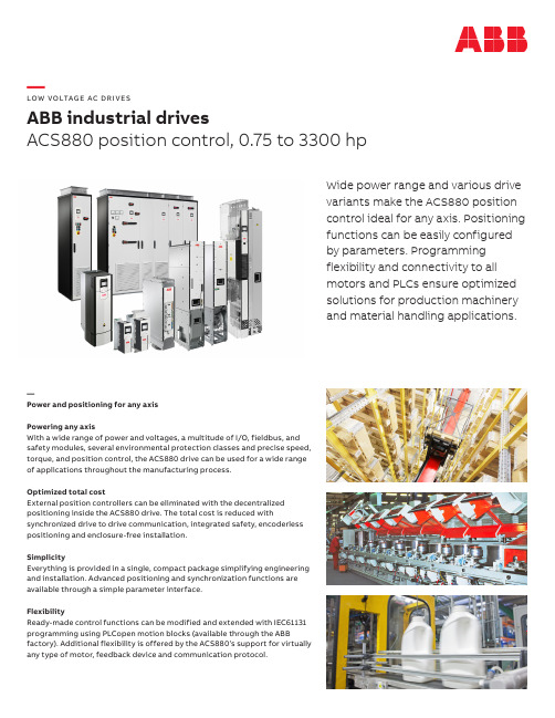
—LOW VO LTAG E AC DR I V E SABB industrial drivesACS880 position control, 0.75 to 3300 hpWide power range and various drivevariants make the ACS880 positioncontrol ideal for any axis. Positioningfunctions can be easily configuredby parameters. Programmingflexibility and connectivity to allmotors and PLCs ensure optimizedsolutions for production machineryand material handling applications.—Power and positioning for any axisPowering any axisWith a wide range of power and voltages, a multitude of I/O, fieldbus, andsafety modules, several environmental protection classes and precise speed,torque, and position control, the ACS880 drive can be used for a wide rangeof applications throughout the manufacturing process.Optimized total costExternal position controllers can be eliminated with the decentralizedpositioning inside the ACS880 drive. The total cost is reduced withsynchronized drive to drive communication, integrated safety, encoderlesspositioning and enclosure-free installation.SimplicityEverything is provided in a single, compact package simplifying engineeringand installation. Advanced positioning and synchronization functions areavailable through a simple parameter interface.FlexibilityReady-made control functions can be modified and extended with IEC61131programming using PLCopen motion blocks (available through the ABBfactory). Additional flexibility is offered by the ACS880’s support for virtuallyany type of motor, feedback device and communication protocol.A C S 880-P H PB 09U -E N R E V A 05/16/2022—For more information please contact your local ABB representative or visit:—We reserve the right to make technical changes or modify the contents of this document without prior notice. With regard to purchase orders, the agreed particulars shall prevail. ABB does not accept any responsibility whatsoever for potential errors or possible lack of information in this document.We reserve all rights in this document and in the subject matter and illustrations contained therein. Anyreproduction, disclosure to third parties or utilization of its contents – in whole or in parts – is forbidden without prior written consent of ABB.Copyright© 2022 ABB. All rights reserved./drives/drives/drivespartners—Technical data—Key featuresEasy to implement, control and maintain a whole manufacturing line• Available with most ACS880 drive variants • Common all-compatible user interface andhardware for position controlled and speed/torque controlled ACS880 drives • Common spare partsReady-made, built-in position control functions Easy implementation via parameter interface.IEC61131 programming with PLCopen motion blocks Well-known implementation. No need to learn a new programming environment. (Through the ABB factory.)Encoderless positioning and position synchronizationLower total cost with improved reliability.Built-in synchronized drive to drive linkNo need for external motion controllers or real-time networks.Supports all types of rotary AC motors and various feedback devices from any motor supplier Support for all common communication protocols Removable memory unit with drive software and settingsEasy software upgrades and drive replacements.Cost and time savings with integrated functional safety features9-year maintenance intervalMinimized machine downtime with long lifetime components and global service network.ACS880 position control program (+N5700)Motors and feedback MotorsAsynchronous, permanent magnet (servo and hightorque), synchronous reluctance motors Feedback devicesHTL, TTL, sin/cos, EnDat, Hiperface, SSI, resolversPosition control functions HomingDifferent modes with home switch,and index pulseAbsolute/relative positioningLinear/rotary/moduloProfiled positioningTarget position, velocity, acceleration/deceleration, jerk 8 predefined sets via DI/fieldbusTarget change on the flyPosition synchronizing/ electrical shaft Reference via master encoder, drive to drive link,virtual master or fieldbusFast position latching With 2 position registers for homing,position correctionJoggingAdjusting an axis while maintaining smoothposition controlControl performance Position control loop 500 µs Drive-to-drive link synchron500 µs Speed control loop 500 µs Torque control loop125 µsProgrammability (through ABB factory only)IEC61131 programming (future)Ladder, IL, CFC, FBD, ST, SFCMotion control library (future)PLCopen motion function blocks andadditional ABB specific blocks Adaptive programming 50 blocks for flexible adjustmentsProgramming toolsDrive application builderfor IEC programmingDrive composer for adaptive programmingACS880 drive product family Power and voltage range 0.75 to 3300 Hp, 3-phase, 230 to 690 VEnclosure UL (NEMA) Type Open, 1 and 12 / IP00 to IP55Configurations Single and multidrive (common DC)MountingWall-mounting up to IP55, stand-alonecabinet-built, modules for cabinet mounting,flange (push through) mounting Supply side variants Integrated or separate supply modules for diode,ultra-low harmonic or regenerative supply Functional safety Supported functionsSafe torque off (STO), Safe stop 1 (SS1), Safe stop emergency (SSE), Safe brake control (SBC), Safely-limited speed (SLS) with/without encoder, Safe maximum speed (SMS), Prevention of unexpectedstartup (POUS), Safe direction (SDI),Safe speed monitoring (SSM), Safe temperature monitoring (SMT)Safety dataPL e, SIL 3Safety communicationPROFIsafe over PROFINET IO。
- 1、下载文档前请自行甄别文档内容的完整性,平台不提供额外的编辑、内容补充、找答案等附加服务。
- 2、"仅部分预览"的文档,不可在线预览部分如存在完整性等问题,可反馈申请退款(可完整预览的文档不适用该条件!)。
- 3、如文档侵犯您的权益,请联系客服反馈,我们会尽快为您处理(人工客服工作时间:9:00-18:30)。
FENA-11 以太网接口板
五 逆变器的更换
R8i逆变模块更换
R8i逆变模块更换
断电等待5分 钟后测量没电
拆除直流 进线螺母
拔通信光纤
R8i变频器模块更换
拆除固定螺母
R8i逆变模块更换
拉出变 频器
固定金 属斜板
直流隔离开关
预充电开
R8I模块
控制单元 BCU-02 R8I模块
预充电控制板 散热风机
R8I控制回路
24电源
BCU-02 控制单元
ZMU-02 储存卡 FENA-11
以太网接口板
FEN-31
编码器接口板
RDCO-02
光纤接口板
防误启安全模块
ABB ACS880 传动培训
*
一、传动控制系统图 二、ACS880 多传动 三、RRU整流模块 四、ACS880 逆变模块 五、变频器的更换
一 传动控制系统图
网线
交换机
光纤
交换机
交换机
交换机
PLC
光纤
CC II 88 55 84
Drve
NDBU-95
NDBU-95
交换机
C I 8 5 8
Drve
R6I/R7I模块
R6I逆变模块 FENA-11 ZCU-14 FDCO-01
控制单元
FENA-11 以太网接口板
ZCU-14 控制单元 FDCO-01 光纤接口板
ZMU-02 储存卡
R5I模块
R5I模块
ZCU-12控制单元
ZMU-02 存储卡 ZCU-12 控制单元
FDCO-01 光纤接口板
停电流程:
所有的传动都停止状态,把送电 旋钮打到左边,办理停电手续 (挂牌、签字)。
注:如果是电站引起跳停,重新 送电:把送电旋钮打到左边,有 预充电回路的变频器开关断开, 送好变压器后再合闸。
急停按钮
逆变模块停送电步骤
有预充电开关的逆变器送电步骤: 1、先送预充电开关,指示灯亮。 2、再送直流隔离开关,指示灯灭。 3、把预充电开关断开。
基本设计理念
公共直流母排 唯一的进线连接 能量共享,电机到电机的
制动而无需制动斩波器或 再生供电单元 降低进线电流 多个传动公用斩波资源 节能 节约电缆、安装简单、降 低维护成本 无需单独的MCC(马达控制 中心) 优化电机控制
单传动和多传动的区别
AC
控制
RMIO
RMIO
变频器
变频器
三 整流模块
ACS880 多传动整流模块
逆变器 滤波器 逆变器
进线开关控制电路
进线柜的控制单元 (BCU)
绝缘检测 急停回路
送电旋钮
急停复位
停电
送电
故障复位
送电流程:
送电旋钮在左边状态,先按一下 急停复位、故障复位按钮,等10 秒,再把送电旋钮打到右边,2秒 左右,听到进线开关合作声音, 整流散热风机运行,送电成功。
C I 8 5 4
MCS
NDBU-95
分站
C I 8 0 1
分站
C I 8 0 1
Profibus 线
变 变变 频 频频 器 器器
网线
PLC控制器与变频器连接图,通过这网络,PLC控制变频器的启动、停止等。
变频器维护网络,变频器参数下载、备份、修改等
二 ACS880 多传动
什么是 ABB 多传动?
RMIO
RMIO 变频器
变频器
单传动:
无公共直流母排 多路输入功率连接 驱动电机的逆变器之间内部不能分配能量,需
要自备制动斩波器制动电阻 无公共直流母排 无公共制动方式 节能 输入电缆不能省
多传动:
公共直流母排 单一输入功率连接 不带制动斩波器或不带再生式供电单元时,
驱动电机的逆变器之间内部分配能量,有发 电,有电动 降低输入线电流,变压器可以选小 针对几个逆变器,公共的制动方式 更加节能 节约电缆、安装、维护成本
