ZXDU68_W201(V1[1].0)50A系列组合电源安装手册
ZXDU58&68组合电源设备培训教材N

27
直流防雷盒
手动下电控制开关
28
29
ZXDU68(V4.0)和ZXDU68(V4.1)的区别 ( ) ( )的区别_1
结构
30
ZXDU68(V4.0)和ZXDU68(V4.1)的区别 ( ) ( )的区别_2
结构
31
ZXDU68(V4.0)和ZXDU68(V4.1)的区别 ( ) ( )的区别_3
1 2
1 2
1 2
15 14 13 12 11 10 9 8 7 6 5 4 3 2 1 交流输 入信号
1 2 3 4 5 6 7 8 9 10 11 12 13 14 15
1 2 3 4 5 6
X2 X7 X6 X5 X4 X3
扩展干 接点 输出 1 2 3 4 5 6 1 2 3 4 5 6 1 2 3 4 5 6 1 2 3 4 5 6 1 2 3 4 5 6
L+
直流防雷
Surge Arrester (DC)
X3Leabharlann X18 备 用直流信 号X6
备 用交 流信号
X20
X19 X24 下电 控制 板信 号 继电器 控制 输出
SC B 板
X17 X16
RS B 板 1
X1
连接 SCB板 的X1 6
1 2 3 4 5 6 7 8 9 10 11
1 2 3 4 5 6 7 8 9 10 11
X2
1 2 3 4 5 6
1 2 3 4 5 6
1 2 3 4 5 6
1 2 3 4 5 6
T1 +12V
T2 +12V
EX12 ALM12 RMT12 CUT12 PWM12 COM12
ZXDU68_T601(V4[1].1R01M01)用户手册
![ZXDU68_T601(V4[1].1R01M01)用户手册](https://img.taocdn.com/s3/m/41df875958fafab069dc02fd.png)
ZXDU2400(V4.3)整流器
• 项目说明:输出电压 • 额定直流输出48V,42V~58V连续可
调
• 交流输入的过、欠压保护及降功率控制 • 1.当交流输入电压≥300V时,关闭后
级DC-DC变换电路和前级功率因数PFC 校正电路。
• 2.当交流输入电压为176V~300V时, 限流点Imax(允许最大电流)=( 53±1)A,整流模块输出100%功率。
亮 绿色 灭
系统已通电 系统未通电
l
亮
系统有故障发生
告警指示灯Alarm 红色 灭
系统无故障发生
交流配电单元位置示意图
•
单空开交流输入方式:交流输入开关配置单个三相空气开关(简称:空开),部件 分布如图所示。
1. 整流器空开 2. 交流防雷器
3. 交流变送器 4. 保护接地排
5. 零线端子 N 6. 交流输入空开
• 具有二次下电保护功能,设有手动和自 动两种下电控制转换装置。用户可根据 实际情况,进行有针对性的二次下电配 置和管理。
系统特点
1. 采用模块化设计和自动均流技术,使系统容量可 以按N+1备份,方便扩容。整流模块配置灵活, 可根据系统供电需要增加或减少。整流模块采用 无损伤热插拔技术,支持即插即用。
ZXDU68组合 电源系统维护
技能培训
教程安排:
上午主要对电源设备维护操作技能理 论知识的培训
下午实际操作,对综合大楼中心机房 电源设备进行维护保养。
学习内容:
电源设备系统简介 电源设备维护保养 知识 设备的应急处理
设备保养意义
随着公司通信的发展,通信设备不断增加 ,而通信从业人员的配置远远不能满足设 备增加的要求。为了保证通信设备的正常 稳定的运行。一方面必须规范巡检制度, 另一方面对巡检人员的巡检质量进行有效 的监督。为此,运用科学管理手段来管理 通信设备,建立通信设备巡检管理制度。 从而能真正的提高巡检质量,及时消除设 备隐患,保证通信设备的正常运行
阳光电源组串式逆变器安装和操作手册说明书

Building 7, No.333 Wanfang Rd, Minhang District, Shanghai, China. 2011122.1 Safety Precautions . . . . . . . . . . . . . . . . . . . . . . . . . . .2.2 Explanations of Symbols . . . . . . . . . . . . . . . . . . . . . . . .3.Installation . . . . . . . . . . . . . . . . . . . . . . . . .3.1 Package . . . . . . . . . . . . . . . . . . . . . . . . . . . . . . . .3.2 Product Overview . . . . . . . . . . . . . . . . . . . . . . . . . . . .3.3 Mounting Location . . . . . . . . . . . . . . . . . . . . . . . . . . .3.4 Installation On-grid PV Inverter . . . . . . . . . . . . . . . . . . . . .3.5 Electrical Connection . . . . . . . . . . . . . . . . . . . . . . . . . .3.5.1 PV Connection . . . . . . . . . . . . . . . . . . . . . . . . . . . .3.5.2 Grid Connection . . . . . . . . . . . . . . . . . . . . . . . . . . .3.5.3 Communication Connection (WIFI / Ethernet / GPRS / RS485) . . . . .4.Operation . . . . . . . . . . . . . . . . . . . . . . . . . .4.1 Control Panel . . . . . . . . . . . . . . . . . . . . . . . . . . . . . .4.2 Menu Structure . . . . . . . . . . . . . . . . . . . . . . . . . . . . .4.3 Setting . . . . . . . . . . . . . . . . . . . . . . . . . . . . . . . . .4.3.1 Startup Setting. . . . . . . . . . . . . . . . . . . . . . . . . . . . .missioning . . . . . . . . . . . . . . . . . . . . . . .6.Shut Down & Restart the Inverter . . . . . . . . . . . . .6.1 Shut Down Procedures . . . . . . . . . . . . . . . . . . . . . . . . .6.2 Restart the inverter . . . . . . . . . . . . . . . . . . . . . . . . . . .7.Maintenance&Trouble Shooting . . . . . . . . . . . . . .7.1 Maintenance . . . . . . . . . . . . . . . . . . . . . . . . . . . . . .7.2 Fault Code and Trouble Shooting . . . . . . . . . . . . . . . . . . .8.Specifications . . . . . . . . . . . . . . . . . . . . . . . .17 18 18 1818 18 18 201.About This Manual1.1 Scope of Validity1.2 Target Group1.3 System DiagramThis manual describes the installation, commissioning, operation andmaintenance of the following on-grid PV inverters produced by Afore NewEnergy:This manual is for qualified personnel. The tasks described in this manual mustonly be performed by qualified personnel.Single-Phase(Two MPPT Trackers)HNS3000TL HNS3600TL HNS4000TL HNS5000TL HNS6000TLSingle-Phase(One MPPT Tracker)HNS3600TL-1Please keep this manual all the time available in case of emergency.About This Manual01The typical connection diagram for the entire PV system is on-grid.W I F I / RS 485Cloud serverPortal webPV Array Circuit Breaker3AC GridPV ArrayPV Inverter2.Safety & Symbols2.1 Safety Precautions1. All work on the inverter must be carried out by qualified electricians.2. The device may only be operated with PV panels.3. The PV panels and inverter must be connected to the ground.4. Do not touch the inverter cover until 5 minutes after disconnecting both DC and AC power supply. Safety & Symbols02Type Max AC Current [A]Rated current of AC breaker[A]Circuit Breaker and Surge Protector Recommendation: SPD: Lightning protection system, refer to the following options: AC side, nominal discharge current 20KA, second grade lightning protection,protection voltage 2.5KVDC side, nominal discharge current 20KA, second grade lightning protection,protection voltage 3.2KV The wiring distance between the inverter and the distribution box should be at least 5 meters.Single-Phase(Two MPPT Trackers)Single-Phase(One MPPT Tracker)HNS3600TL-11825Note:The Inverter can be only connected to low-voltage grid.(220/230Vac, 50/60Hz).5. Do not touch the inverter enclosure when operating, keep away from materials that may be affected by high temperatures.6. Please ensure that the used device and any relevant accessories are disposed of in accordance with applicable regulations.7. Afore inverter should be placed upwards and handled with care in delivery. Pay attention to waterproof. Do not expose the inverter to water, rain, snow or spray.8. Alternative uses, modifications to the inverter not recommended. The warranty can become void if the inverter was tampered with or if the installation is not in accordance with the relevant installation instructions.Afore inverter strictly comply with relevant safety standards. Please read andfollow all the instructions and cautions during installation, operation and maintenance.Safety & Symbols032.2 Explanations of SymbolsImportant NotesRead all instructions carefully. Failure to follow these instructions,3.Installation3.1 PackageUnpackingOn receiving the inverter, please check to make sure the packing and all components are not missing or damaged. Please contact your dealer directly for supports if there is any damage or missing components.Package List Open the package, please check the packing list shown as below.Installation 04Note: The HNS3600TL-1 is 1 pair of DC plug connector, theHNS3000-6000TL is 2 pairs.689101Overview of the Connection AreaThe following picture shows the assignment of the individual connection areas on the bottom of the inverter.Installation053.2 Product OverviewThe inverters are designed for indoor and outdoor installation (IP65), to increase the safety, performance and lifespan of the inverter, please selectthe mounting location carefully based on the following rules: The inverter should be installed on a solid surface, far from flammable or corrosion materials, where is suitable for inverter’s weight and dimensions. The ambient temperature should be within -25℃ ~ 60℃ (between -13 °F and140°F).The installation of inverter should be protected under shelter. Do not expose the inverter to direct sunlight, water, rain, snow, spray lightning, etc.Installation 063.3 Mounting LocationThe inverter should be installed vertically on the wall, or lean back on planewith a limited tilted angle. Please refer to below picture.Installation073.4 Installation On-grid PV Inverter Leave the enough space around inverter, easy for accessing to the inverter, connection points and maintenance.Step 2300mm500mm3.5 Electrical Connection3.5.1 PV ConnectionThe inverter is equipped with 2 MPPT channels, each of which contains a PVstring input. For best results, please ensure that each MPPT channel isconnected to a PV string separately. Otherwise, the inverter will activate voltageor automatic current protection.·The open-circuit voltage and short-circuit current of PV string must not exceed inverter’s range·The isolation resistance between PV string and ground must exceed 10 kΩ·The polarity from PV strings are correct·Use the DC plugs in the accessory·The lightning protector should be equipped between PV strings and inverter ·Disconnect all of the PV (DC) switch during wiringWarning:The fatal high voltage may on the DC side, please comply withelectric safety when connecting.Please make sure the cable connected in correct polarity withinverter, otherwise inverter could be damaged.Installation09Note :It is strongly recommended to connect by two strings of panels for models of two MPPT channels, e.g. HNS3000-6000TL.210 solar panels should connect from PV side A and B as the Y -shaped, setting PV model parallel and PV side voltage notexceed 500V one MPPT; other solar panels we are recommend you though dual MPPT input the cables, also no exceed 450VNote:Please use PV connector crimperNote:You’ll hear click sound whenthe connector assembly is correctNote:PV cable suggestion Cross-section 4 mmThe on-grid PV inverters work with grid (220/230/240 Vac, 50/60 Hz).The external AC switch should be installed between inverter and grid to isolate from grid. Please make sure below requirements are followed before connecting AC cable to the inverter.·The AC (grid) voltage must not exceed inverter’s range·The phase-line from AC distribution box are correctly connected ·Use the AC plugs in the accessory·The surge protector should be equipped between grid and inverter ·Disconnect the AC (grid) switch during wiringInstallation103.5.2 Grid ConnectionWarning:The fatal high voltage may on the AC side, please comply with electric safety when connecting.Please make sure the right line of AC grid connected with inverter, otherwise inverter could be damaged.AC line goes through AC terminal waterproof head and capNote:AC cable suggestion Cross-section4 mm11InstallationConnect AC line, Live line (L), Neutral line (N) and Ground Wire (PE) according to polarity.1. Connect AC terminals and waterproof head, tightenthe cap, make sure they clip closely together.2. Connect AC connector to AC terminal of the inverter.3. Afeer making sure that it is firmly insered, tightenthe sleeve on the AC connector to the right and hear aclick.12Installation3.5.3 Communication ConnectionThe monitoring module could transmit the data to the cloud server, and display the data on the PC, tablet and smart-phone.Install the WIFI / Ethernet / GPRS / RS485 CommunicationWIFI / Ethernet / GPRS / RS485 communication is applicable to the inverter. Please refer to "Communication Configuration Instruction" for detailedinstruction.Installation13For single-phase inverter, please follow below pin order RS485A(Pin 7) to single-phase meter (Pin 24)RS485B(Pin 8) to single-phase meter (Pin 25)4.5 Zero-injection Smart Meter (Optional)Smart meter is an intelligent control equipment which is used for on-grid inverters. Its main function is to measure the forward and reverse power on Note:Operation14Note:The Inverter could be connected in parallel with Smart Meter,make sure the total load power not exceed Smart Mater’s limitation.GridPV InverterPV ArrayPV ArrayPV ArrayNote:Please refer to "Zero InjectionSmart Meter Installation andOperation Manual" for detailed instruction.Operation155.2 Menu StructureSecond Level MenuOperation175.3.3 Frequency RangeMain MenuENTENTENTENTENTENTENTENTNote:The parameters setting only works after the inverter is restarted.ENTENTENTENTENTENTUP/DOWNUP/DOWNUP/DOWNUP/DOWN set protection timeUP/DOWN set level 2UP/DOWNUP/DOWNUP/DOWNUP/DOWN set level 1UP/DOWN set level 2UP/DOWN set level 1UP/DOWNUP/DOWN set protection timeUP/DOWN set level 2UP/DOWNUP/DOWNUP/DOWNUP/DOWN set level 1UP/DOWN set level 2UP/DOWN set level 120Maintenance&Trouble Shooting Trouble-Shooting ListOperation165.3.1 Startup5.3 SettingExplanation of LCD Display Content5.3.2 Voltage RangeMain MenuENTENTUP/DOWNUP/DOWNENTENTUP/DOWN Adjust the time andUP/DOWNCommissioning18Before starting up commissioning at site, please make sure below procedures and requirements are fully meet.• Mounting location is meet the requirements.• All of the electrical wiring is firmly connected, including PV wiring, Grid wiring and Earth wiring.• The inverter setting has been finished accordingly to local standards or regulations.Commissioning Procedures• Turn on the AC switch between inverter output and the public grid;• Turn on the DC switch on the inverter;• Turn on the PV switch of the system.6. Commissioning7. Shut down & restart inverter• Turn off the DC switch on the inverter.• Turn off the DC switch between PV panels and the inverter (if any).• Close the AC switch between the inverter and the public grid.• Shut down the inverter according to Chapter 7.1.• Start-up the inverter according to Chapter 6.7.2 Restart7.1 Shut downNote:The inverter will be operable after minimum 5 minutes.5.Operation 5.1 Control Panel○2○3○1○○45○○○678Operation 15Shut Down & Restart the Inverter19Periodically maintenance are necessary, please follow steps as below. PV connection: twice a yearAC connection : twice a yearEarth connection: twice a yearHeat sink: clean with dry towel once a year.Fault messages will be displayed when fault occurs, please according to trouble- shooting table find related solutions.8. Maintenance&Trouble Shooting8.1 Maintenance8.2 Trouble Shooting21 Maintenance&Trouble Shooting22Maintenance&Trouble Shooting8.Specifications Specifications23Max. DC Power ( W )Max. DC Voltage ( V )MPPT Voltage Range ( V ) MPPT Full Power Voltage Range ( V ) Rated Input Voltage ( V )Start-up Voltage ( V )Max. Input Current ( A )Max. Short Current ( A )No. of MPP Tracker /No. of PV StringInput Connector TypeMax. Output Power ( W ) Nominal Output Power ( W ) Max. Output Current ( A ) Nominal Output Voltage ( V )Grid Voltage Range Nominal Output Frequency ( Hz ) Grid Frequency Range Output Power FactorOutput Current THDMax. EfficiencyEuro Efficiency°C180Vac-276Vac (According to local standard)45~55Hz/54~66Hz (According to local standard)1 default (adjustable from 0.8 leading to 0.8 lagging)L/N/PE, 220Vac, 230Vac, 240VacIntegrated(Type III)RS485 / WiFi / Wire Ethernet / GPRS (op ti onal)EN/IEC 61000-6-2, EN/IEC 61000-6-3, EN61000-3-2, EN61000-3-3, EN61000-3-11, EN61000-3-12IEC 60068, IEEE1547,EN62109PV Reverse Polarity Protection PV Insulation Resistance Detection AC Short Circuit ProtectionAC Over Current ProtectionAC Over Voltage ProtectionAnti-Islanding Protection Residual Current Detection Over Temperature Protection Integrated DC switchSurge ProtectionDimensions (W x H x D, mm) Weight ( kg )Protection Degree Enclosure MaterialAmbient Temperature Range ( ) Humidity RangeTopology Communication Interface Cooling ConceptNoise Emission ( db )Night Power Consumption ( W ) Max. Operation Altitude ( m )EMC StandardSafety StandardGrid-connec ti on3607014 x 218 x 22/2330030001598.20%97.80%YESYESYESYESYESYESYES450060070-550110-550MC43607014 x 218 x 22/23960360017.598.20%97.82%YESYESYESYESYESYESYES4000540060070-550130-550MC43607014 x 218 x 22/2440040002098.20%97.85%YESYESYESYESYESYESYES10<28358×360×142600060070-550145-550MC43607014 x 218 x 22/25500500024<3%50/6098.20%97.90%YESYESYESYESYESYESYESConvection<1IP65AluminumTransformerless0-100%700060070-550180-550MC43607014 x 218 x 22/26600600028.798.20%97.92%YESYESYESYESYESYESYES840060070-550220-550MC4YES YES YES YES YESYES YES YES YES YES 3960360017.598.20%97.80%3607014181/1420060070-500130-500MC4YESYESYESYESYESYESYESYESYES-25 ~ +60°C (Derating 45°C)EN50549-1, EN50438, RD 1699,UNE 217001, RD 413, IEC61727, IEC62116, IEC61683, VDE4105, UL1741 VDE0126 AS4777.2 NB/T 32004-2018, UNT C 15-712-1, ABNT NBR 16149, ABNT NBR 16150。
座充说明书
内部资料,严禁外传设备外观及常用按键介绍 (5)i60巴枪介绍 ............................................................................. (5)(2)i80巴枪介绍 (8)i60、i80连接wifi操作 ............................................................... 9 i60连接wifi操作 (10)i80连接wifi操作 (11)i60、i80拨号操作 (14)i60拨号操作 ............................................................................... 14i80拨号操作 ............................................................................... 15i60、i80系统常用功能介绍与问题故障 (24)签收、未签收、快速签收 (24)寄件录单 ............................................................................. (27)收件扫描 ............................................................................. (28)快件扫描 ............................................................................. (29)消息通知、电子手册 (33)查询统计 ............................................................................. (35)我的工具 ............................................................................. (38)常见问题和故障处理 (39)触屏校准 ............................................................................. (39)内部资料,严禁外传凯立巴枪巴枪使用与操作说明 ..................................................41设备外观以及常用按键介绍 (42)凯立系列巴枪介绍 (42)凯立巴枪常用按键介绍 (44)系统常用功能介绍以及问题故障 ...............................................45采集.............................................................................. (45)查询.............................................................................. (45)上传.............................................................................. (46)快件状态查询 .............................................................................47区域查询 ............................................................................. (47)设置.............................................................................. (48)常见问题和故障处理 (49)扫描宝安装及注意事项 (50)一、扫描宝下载。
NDW1A系列安装使用说明书
NDW1A 系列安装使用说明书
■
■
“”
“”
3
NDW1A 系列安装使用说明书
■ ■
■
4
NDW1A 系列安装使用说明书
5
NDW1A 系列安装使用说明书
6
NDW1A 系列安装使用说明书
7
NDW1A 系列安装使用说明书
8
NDW1A 系列安装使用说明书 9
NDW1A 系列安装使用说明书 39
NDW1A 系列安装使用说明书 40
NDW1A 系列安装使用说明书 41
NDW1A 系列安装使用说明书 42
NDW1A 系列安装使用说明书 43
NDW1A 系列安装使用说明书 44
NDW1A 系列安装使用说明书 45
NDW1A 系列安装使用说明书 46
下图为控制器输入输出接口
NDW1A-2000/3200/6300 辅助开关接线方式
24
NDW1A 系列安装使用说明书
25
NDW1A 系列安装使用说明书
²
²
26
NDW1A 系列安装使用说明书 27
NDW1A 系列安装使用说明书 28
NDW1A 系列安装使用说明书 29
NDW1A 系列安装使用说明书 30
注:1.断路器的当前状态为不带电,断开,连接,未贮能; 2.虚线部分由用户接; 3.电源——若 Q、F 、B、M、控制器电源不同时,分别接电源;
23
NDW1A 系列安装使用说明书 4.当主回路电流小于 0.4In 时,端子号 1、2 必须接辅助电源; 5.该原理图适用于带通讯功能的产品。 6.断路器辅助端子接线方式见附图。 7.二次端子可接导线容量,最小为 0.2mm²/24AWG,最大为 1.5mm²/16AWG。
亿维自动化 X系列BD扩展板使用说明书

3.4. X-2AO-BD 产品说明书 ............................................................................................................ 19
3.4.1. 产品概述 ............................................................................................................................ 19
2.1.4. 模拟量 BD 扩展板地址对照表........................................................................................... 7
3. BD 扩展板详细参数..................................................................................................................................... 9
服务热线:4000 300 890
3.1.4. 安装及接线图 .................................................................................................................... 10
3.1.5. 应用说明 .............................................................................................................................11
电源设备安装指南说明书

ContentsDescription Page 1.0 Setup ................................21.1 Before Installation .....................21.2 Installation ..........................3For AC Applications .....................3For DC Applications ....................31.3 Wiring ..............................31.3.1 Series Wiring Applications ...........31.3.2 Parallel Wiring Applications ..........41.3.3 Wiring Note ......................41.4 Apply Power .........................41.5 Specifications ........................41.6 Warnings ............................51.7 Warranty . (5)Installation Instructions for EatonSurge Protective Device XXCFXXX10-DINand XXCFXXX10-DIN2XXCFXXX10-DINXXCFXXX10-DIN22Instruction Manual IM01005020E Rev 4Effective October 2018Installation Instructions for EatonSurge Protective Device XXCFXXX10-DIN and XXCFXXX10-DIN2EATON WARNINGHAZARDOUS VOLTAGES PRESENTIMPROPER INSTALLATION OR MISAPPLICATION OF THESE DEVICES MAY RESULT IN SERIOUS INJURY TO INSTALLER AND/OR DAMAGE TO ELECTRI-CAL SYSTEM OR RELATED EQUIPMENT. READ AND UNDERSTAND ALL INSTRUCTIONS BEFORE BEGINNING INSTALLATION. PROTECTIVE EYE-WEAR SHOULD BE WORN WHENEVER WORKING AROUND HAZARDOUS VOLTAGES. THIS DEVICE CONTAINS NO SERVICEABLE PARTS.NOTICEALL INSTRUCTIONS AND MEASUREMENTS MUST BE COMPLETED BY A LICENSED/QUALIFIED ELECTRICIAN IN ACCORDANCE WITH THE U.S. NATIONAL ELECTRICAL CODE, STATE AND LOCAL CODES OR OTHER APPLI-CABLE COUNTRY CODES. THE U.S. NATIONAL ELECTRICAL CODE AND STATE AND LOCAL REQUIREMENTS (OR OTHER APPLICABLE COUNTRY CODES) SUPERSEDE THIS INSTRUCTION.Catalog Number Voltage Range Protection Modes VPR MCOV In SCCRPeak Surge Current PhaseXXCF02410-DIN 1 5 - 38 Vdc L-NL-G N-G N/A N/A N/A N/A 8kAXXCF04810-DIN 124 - 65 Vdc L-N L-G N-G N/A N/A N/A N/A 26kA XXCF12010-DIN248 - 149 Vdc 1 100 - 127 VacL-N L-G N-G500 500 500150 150 1503kA10kA40kA Catalog NumberVoltage Range Protection Modes VPR MCOV In SCCR Peak Surge Current Phase XXCF12010-DIN2348 - 149 Vdc 1 100 - 127 Vac L-NL-G N-G 560 560 560127 127 1273kAN/A30kAXXCF24010-DIN23150 - 300 Vdc 1 200 - 240 VacL-N L-G N-G980 990 960254 254 2543kA N/A 30kA1 UL 1449 4th Edition does not list SPD products rated less than 110 Vac or DC voltages.2UL 1449 4th Edition, UL 1283 7th Edition 3UL 1449 4th Edition, IEC61000 - 4.51.0 SetupVerify that system voltages do not exceed those listed in Section 1.5, Specifications.•All AC measurements should be completed with an RMS voltme-ter.• All DC measurements should be completed with a DC voltmeter. •DO NOT INSTALL THE SURGE PROTECTIVE DEVICE IF MEASURED VOLTAGE EXCEEDS MAXIMUM OPERATING LIMITS.Choose location for the Surge Protective Device installation so that maximum separation can be maintained between input leads, output leads and ground leads.1.1 Before InstallationREMOVE POWER FROM ELECTRICAL SYSTEM BEFORE MOUNTING THE SURGE PROTECTIVE DEVICE.•The Surge Protective Device MUST be mounted within an enclo-sure to assure personnel safety from exposed terminals.IMPORTANTTHE SURGE PROTECTIVE DEVICE SHOULD BE LOCATED SO THAT THE SHORTEST POSSIBLE CONDUCTOR LENGTH MAY BE USED. THE SURGE PROTECTIVE DEVICE SHOULD BE MOUNTED TO ALLOW MAXIMUM SEPARATION BETWEEN INPUT AND OUTPUT WIRING.•The Surge Protective Device contains no position-oriented compo-nents and can be mounted upside down or sideways.•The Surge Protective Device should be placed in electrical circuit so that it is the last device in the circuit before equipment to be protected.•The Surge Protective Device may be installed in series with the load or, if the load current exceeds 15A, it may be installed in parallel.3Instruction Manual IM01005020E Rev 4Effective October 2018Installation Instructions for EatonSurge Protective Device XXCFXXX10-DIN and XXCFXXX10-DIN2EATON 1.2 InstallationTHE SURGE PROTECTIVE DEVICE MUST BE CONNECTED TO ELECTRICAL SYSTEM WITH A CIRCUIT BREAKERFor AC Applications•1 - Single Pole / Single Throw 15A circuit breaker. The Interrupting Rating of the Circuit Breaker Shall Not Be Less Than the Available Fault Current. Circuit Breaker Ratings of 15A, 240V/415V, 10kA Min. AIC Rating.•Note: Pre-existing breakers of the rated load size may be utilized if provisions for multi-conductor connections are made according to NEC 110-14A.•If Neutral wire is to be utilized as L2, then a circuit breaker must be provided for that phase.For DC Applications•DC units to be installed after an overcurrent protective device that is rated not to exceed 100% of the current rating of the unit.REMOVE POWER FROM ELECTRICAL SYSTEM BEFORE INSTALLING THE SURGE PROTECTIVE DEVICE.Mechanically mount the Surge Protective Device.•The Surge Protective Device should be mounted to allow maxi-mum separation between input and output wiring.•The Surge Protective Device contains no position-oriented compo-nents and can be mounted upside down or sideways.•The Surge Protective Device should be placed in electrical circuit so that it is last device in circuit before equipment to be pro-tected.1.3 WiringNOTICEAN INSULATED GROUNDING CONDUCTOR THAT IS IDENTICAL IN SIZE AND INSULATION MATERIAL AND THICKNESS TO THE GROUNDED AND UNGROUNDED CIRCUIT SUPPLY CONDUCTORS, EXCEPT THAT IT IS GREEN WITH OR WITHOUT ONE OR MORE YELLOW STRIPES, IS TO BE INSTALLED AS PART OF THE CIRCUIT THAT SUPPLIES THE FILTER. SEE TABLE 250-122 OF THE NATIONAL ELECTRIC CODE (NEC) REGARDING THE APPROPRIATE SIZE OF THE GROUNDING CONDUCTOR.THE GROUNDING CONDUCTOR IS TO BE GROUNDED TO EARTH AT THE SERVICE EQUIPMENT OR OTHER ACCEPTABLE BUILDING EARTH GROUND SUCH AS THE BUILDING FRAME IN THE CASE OF HIGH-RISE STEEL FRAME STRUCTURE.ANY ATTACHMENT-PLUG RECEPTACLES IN THE VICINITY OF THE SURGE PROTECTIVE DEVICE ARE TO BE GROUNDING TYPE, AND THE GROUNDING CONDUCTORS SERVING THESE RECEPTACLES ARE TO BE CONNECTED TO EARTH GROUND AT THE SERVICE EQUIPMENT OR OTHER ACCEPTABLE BUILDING EARTH GROUND SUCH AS THE BUILDING FRAME IN THE CASE OF HIGH-RISE STEEL FRAME STRUCTURE.PRESSURE TERMINAL OR PRESSURE SPLICING CONNECTORS AND SOL-DERING LUGS USED IN THE INSTALLATION OF THE SURGE PROTECTIVE DEVICE SHALL BE IDENTIFIED AS BEING SUITABLE FOR THE MATERIAL OF THE CONDUCTORS. CONDUCTORS OF DISSIMILAR METALS SHALL NOT BE INTERMIXED IN A TERMINAL OR SPLICING CONNECTOR WHERE PHYSI-CAL CONTACT OCCURS BETWEEN DISSIMILAR CONDUCTORS UNLESS THE DEVICE IS IDENTIFIED FOR THE PURPOSE AND CONDITIONS OF USE.CONDUCTORS SHOULD BE TWISTED TOGETHER TO REDUCE IMPEDANCE FACTOR. EXCESSIVE WIRE LENGTH AND SHARP BENDS DEGRADE FIL-TER PERFORMANCE; THEREFORE, AVOID EXCESSIVE WIRE LENGTH AND SHARP BENDS.1.3.1 Series Wiring Applications•Connect incoming system GROUND wire to terminal labeled G on unprotected end (labeled as LINE ).•Connect load side GROUND wire to terminal labeled G on pro-tected end (labeled as EQUIP ).For AC Applications (See Figures 1 and 2)•Connect incoming system NEUTRAL wire to terminal labeled N on unprotected end (labeled as LINE ).•Connect load side NEUTRAL wire to terminal labeled as N on protected end (labeled as EQUIP ).•Connect incoming system HOT wire to terminal labeled L on unprotected end (labeled as LINE ).•Connect load side HOT wire to terminal labeled as L on protected end (labeled as EQUIP ).For DC Applications (See Figure 3)•Connect incoming system NEGATIVE wire to terminal labeled N on unprotected end (labeled as LINE ).•Connect load side NEGATIVE wire to terminal labeled as N on protected end (labeled as EQUIP ).•Connect incoming system POSITIVE wire to terminal labeled L on unprotected end (labeled as LINE ).•Connect load side POSITIVE wire to terminal labeled as L on pro-tected end (labeled as EQUIP ).4Instruction Manual IM01005020E Rev 4Effective October 2018Installation Instructions for EatonSurge Protective Device XXCFXXX10-DIN and XXCFXXX10-DIN2EATON Figure 4. Single Phase Parallel AC ApplicationFigure 5. Split Phase Parallel AC Application (Shown with Neutral Utilized as L2)Figure 6. Parallel DC Application1.3.2 Parallel Wiring Applications•Connect incoming system GROUND wire to terminal labeled G on unprotected end (labeled as LINE ).For AC Applications•Connect incoming system NEUTRAL wire to terminal labeled N on unprotected end (labeled as LINE ).•Connect incoming system HOT wire to terminal labeled L on unprotected end (labeled as LINE ).•This will install the SPD in parallel with the supply and it will not be subjected to any load current.For DC Applications•Connect incoming system NEGATIVE wire to terminal labeled N on unprotected end (labeled as LINE ).•Connect incoming system POSITIVE wire to terminal labeled L on unprotected end (labeled as LINE ).•This will install the SPD in parallel with the supply and it will not be subjected to any load current.ote:N For ungrounded or isolated control transformer secondary, DO NOT CONNECT Ground terminal on either LINE or EQUIP side.1.3.3 Wiring Noteote:N A circuit breaker or fuse must be inserted in the LINE input side of the incoming supply. Rating will be according to the required load current andapplies to Series connections only.1.4 Apply PowerApply power to system. Indicator light should glow. If light does not glow, remove power and contact supplier1.5 SpecificationsDescription RatingsCatalog Number XXCFXXX10-DIN2Agency ApprovalsUL1449 4th Edition, IEC61000 - 4.5Terminal Wire Gauge Range 30 – 12 AWG Terminal Screw Torque 12 in-lbOperating Temperature -40F(-40C) to +140F(+60C)System voltages DC AC5 - 38 Vdc, 24 - 65 Vdc, 48 - 149 Vdc, 150 - 300 Vdc 100 - 127 Vac, 200 - 240 Vac Amps*10ACircuit Breaker 15A, 240V/415V, 10kA Min. AIC Rating Input Power Frequency 50/60 HzWarranty5 Years, 10 Years if registered on /spd RoHS CompliantYes* Amp rating is for series connection only. Parallel connection is not current dependent.Figure 7. XXCFXXX10-DIN Product Dimensions5Instruction Manual IM01005020E Rev 4Effective October 2018Installation Instructions for EatonSurge Protective Device XXCFXXX10-DIN and XXCFXXX10-DIN2EATON Figure 8. XXCFXXX10-DIN2 Product Dimensions1.6 WarningsWARNINGALL DEVICES LISTED IN THIS MANUAL CONTAIN NO SERVICEABLE PARTS.WARNINGXXCFXXX10-DIN2 DEVICES ARE SUITABLE FOR USE IN CLASS I, DIVISION 2 GROUPS A, B, C AND D OR NON-HAZARDOUS LOCATIONS ONLY.WARNINGEXPLOSION HAZARDDO NOT DISCONNECT EQUIPMENT UNLESS POWER HAS BEEN SWITCHEDOFF OR THE AREA IS KNOWN TO BE NON-HAZARDOUS.1.7 WarrantyEaton warrants these products for a period of 5 years from the date of delivery to the purchaser, 10 years if registered on /spd, to be free from defects in both workmanship and materi-als. Eaton assumes no risk or liability for results of the use of the products purchased from it, including but without limiting the gen-erality of the foregoing; (1) The use in combination with any electri-cal or electronic components, circuits, systems, assemblies, or any other materials or substances; (2) Unsuitability of any product for use in any circuit or assembly.Purchaser’s right under the warranty shall consist solely of requiring Eaton to repair, or at Eaton’s sole discretion, replace, free of charge, F .O.B. factory, and defective items received at said factory or failure to give any advice or recommendations by Eaton shall not constitute any warranty by or impose any liability upon Eaton. The foregoing constitutes the sole and exclusive liability of Eaton AND IS IN LIEU OF ANY AND ALL OTHER WARRANTIES EXPRESSED, IMPLIED OR STATUTORY AS TO THE MERCHANTABILITY , FITNESS FORPURPOSE SOLD, DESCRIPTION, QUALITY , PRODUCTIVENESS OR ANY OTHER MATTER.In no event shall Eaton be liable for special or consequential dam-ages or for delay in performance of the warranty.This warranty does not apply if the product has been misused, abused, altered, tampered with, or used in applications other than specified on the nameplate. At the end of the warranty period, Eaton shall be under no further warranty obligation expressed or implied.The product covered by this warranty certificate can only be repaired or replaced by the factory. For help on troubleshooting the Critical Protection Product, or for warranty information, call 1-800-809-2772, Option 4, sub-option 2. Repair or replacement units will be returned collect. If Eaton finds the return to be a manufacturer’s defect, the product will be returned prepaid.Instruction Manual IM01005020E Rev 4 Effective October 2018Installation Instructions for Eaton Surge Protective Device XXCFXXX10-DIN and XXCFXXX10-DIN2EATON 67Instruction Manual IM01005020E Rev 4Effective October 2018Installation Instructions for EatonSurge Protective Device XXCFXXX10-DIN and XXCFXXX10-DIN2EATON Instruction Manual IM01005020E Rev 4 Effective October 2018Installation Instructions for Eaton Surge Protective Device XXCFXXX10-DIN and XXCFXXX10-DIN2EatonElectrical Sector1000 Eaton Boulevard Cleveland, OH 44122United States877-ETN-CARE (877-386-2273) © 2018 EatonAll Rights ReservedPrinted in USAPublication No. IM01005020E Rev 4 / TBG000458 October 2018Eaton is a registered trademarkAll other trademarks are property of their respective owners.。
安装使用说明书

帅能电涡轮增压器,通过叶轮有压推进空气,增加进入发动机汽缸的空气量,能有效地增大发动机的空燃比,燃料燃烧更加充分,在不增加发动机油耗的前提下,提升发动机比功率,或保持发动机原有动力的前提下,相应地降低油耗,并能有效改善排气质量。
本公司出产的S-eTurbo-V型帅能电涡轮增压器,是对S-eTurbo-IV型电涡轮的全面技术升级和改进,不仅适用于对存量车的DIY改装,而且更加专业化,亦适用于整车配套。
S-eTurbo-V型帅能电涡轮增压器其特点:●散热一体化筒体壁面成为高发热的无刷电机驱动功率管的冷却器(专利权项),驱动功率管始终于强制紊流空气的流动通道,冷却效果最好,运行稳定可靠。
即使在汽车发动机舱的高热环中,驱动控制器也无过热烧损之忧。
●机电一体化压铸铝筒体直接内臵专有强力无刷电机,结构更加紧凑、专业,散热效果更好,完全克服了IV型不稳定的缺陷。
机电一体化设计,没有单体商品电机,杜绝了部分商家的山寨拼凑。
●无级调速无刷电动机的驱动控制器以发动机节气门的相位信号为控制源,独立于汽车发动机电控单元,根据节气门的相位信号线性控制电涡轮的推风量,实现与机械增压器完全相同的平滑增压,适用于各种拉线节气门和电子节气门发动机。
●日本进口轴承电涡轮的受用寿命,极大程度地取决于轴承的使用寿命。
S-eTurbo-V型帅能电涡轮,采用高成本的日本进口轴承,将轴与轴承的摩擦降到极低的程度,并大大地改善了轴的传热条件,确保本款电涡轮的使用寿命在12-15万公里。
●自设参数电涡轮启动相位、启动强度和满荷相位,用户均可根据个性喜好,通过相应电位器自行设定或调节,一改S-eTurbo-IV型在出厂时,由厂家设定运行参数、用户不能改变的不足。
●压铸铝筒体筒体和法兰,均采用压铸铝材质,并经黑色阳极氧化后进行表面喷漆,不仅机电一体化的设计理念得以实施,良好的散热性能确保了电机的持续稳定运行,同时更显其专业性和精工品质。
●内置光隔驱动控制器内臵光隔电路,将电涡轮控制电路与汽车ECU物理隔离,完全避免了电涡轮与汽车ECU的相互干扰。
ZXDU68_W201(V1.0)50A系列组合电源安装手册

柔性电源硬件配件安装指南说明书

PC 132Catalog No. 535-20030Printed in U.S.A.Form 52C,P-11SI Pg 18-01Replaces: 52S-34SI,52S-35SI Book 14T ab 9a 11aInstallation InstructionsHardwire Accessory KitFor Use WithPackaged Terminal Air Conditioneror Heat PumpStep 7 — Separate Molex connectors from hardwire and, referring to Fig. 4, make the following wiring connections:•Connect Black wire to where plain wire of power cord was originally connected•Connect Red wire to where ribbed wire (capacitor) power cord was originally connected•Connect Green wire where ground was originally connected.NOTE: Leave approximately 3 in. of plug assembly outside the control box through the power cord access hole for easy access in the future. See Fig. 5.Step 8 — Close control box, and secure using 2 screws re-moved earlier.Step 9 — Connect male and female Molex connectors. Push Molex connector and excess wiring back into control box through power cord access hole. See Fig. 5.Step 10 — Attach hardwire access panel with screw saved from Step 3. See Fig. 6.Step 11 — Replace front panel.NOTE: Be sure conduit is routed through notch on front panel. Step 12 — Make wiring connections in field-supplied junc-tion box. See Fig. 7.Step 13 — Restore power to unit.23DISCONNECT HARDWIRE FOR CHASSISREMOVALStep 1 — Disconnect all power to unit.Step 2 — Remove front panel.Step 3 — Remove access cover from control box and dis-connect plug assembly. See Fig. 3 and 5.Step 4 — Follow instructions in owner’s manual for chassisremoval.When removing chassis from wall sleeve, disconnect power at main fuse or circuit breaker first, to avoid possible electrical shock.Manufacturer reserves the right to discontinue, or change at any time, specifications or designs without notice and without incurring obligations.PC 132Catalog No. 535-20030Printed in U.S.A.Form 52C,P-11SI Pg 48-01Replaces: 52S-34SI,52S-35SI Copyright 2001 CAC/BDPBook 14T ab 9a 11a。
ZRoadZ 引导灯配件安装说明书

FIG 1FIG 2Page 1and disconnect the battery.* APPLICATION MODELS VARY. WE RECOMMEND TO VERIFY FITMENT BEFORE BEGINNING INSTALLATION PROCESS.* IMAGES FEATURED IN THE INSTRUCTION DOCUMENTS MAY NOT ALWAYS EXACTLY MATCH YOUR MODEL OR PART.- (1) Driver Side Mounting Bracket- (1) Passenger Side. Mounting Bracket- Air Hose & Nozzle- Alcohol Cleaning Solution - Cleaning RagRatchet Extensions - Various Wrenches - Dikes or Snips - Torq Bit Set - Heat GunTools RequiredLED LIGHTS includedhardware includedParts included- No LED Lights Included - (2) 3” LED Light PodsZ364941 Z364941-KIT2(2) - M6 x 1mm Black Hex Round Screws (2) - 1/4” Black Flat Washers(2) -.750” x .75” Aluminum Spacers (2) - M8 x 20mm Hex Head Cap Screws (2) - M8 Split Lock Washers(2) - Stainless Steel M8 Hex Nuts(1) - Double Terminal Power Cable Wiring HarnessInstallation Guide2018 JEEP WRANGLER JL PROFESSIONAL INSTALL RECOMMENDEDFIG 3FIG 4FIG 6FIG 6FIG 5FIG 6FIG 7FIG 8FIG 9Parts are PATENT PENDING. All Rights Reserved - Copyright ©2018 - ZROADZ LED, INC.wall, garage door or other solid barrier. We recommend checking from a distance FIG 10FIG 11FIG 6FIG 6FIG 6FIG 17FIG 18FIG 19LED Light Bracket Installation - Process complete Parts are PATENT PENDING. All Rights Reserved - Copyright ©2018- ZROADZ LED, INC.ZROADZ warrants its grille products to be free from defects in material and workmanship for the lifetime of the grille. ZROADZ warrants the finish of its grille products for a 3 year period beginning at the time of sale to the end user. These warranties are limited warranties and do not cover abuse, modification or improper installation nor do they cover finish failure caused by caustic cleaning agents, road salts or other chemicals. ZROADZ reserves the right to repair or replace a defective product at its sole discretion. Any ZROADZ product must be returned to ZROADZ for warranty consideration and must be returned at the customer’s expense. In the event that the product is deemed to be defective, the repaired or replaced item will be returned via a surface shipping method to the customer at ZROADZ expense. No provision is made for any labor, rental car or other costs incurred by the failure of its products.LED Lights & LED Light Bars operate at relatively high currents and should only be installed by qualified personnel with experience in switched / relayed high draw DC Circuits.- Light Bars are designed for use only with standard 12v DC power systems- Light Bars are for OFF-ROAD USE ONLY. Check your local laws & regulations regarding vehicle mounted lights.- Some Light Bars are equipped with waterproof connectors while others are simply pig-tailed - Red Wires = POSITIVE | Black Wires = NEGATIVE- ALWAYS install your lights on a fused circuit. Basic fusing guidelines: maximum 5A for every 10” of LED Light Bar.PLEASE CONSULT YOUR LOCAL AUTOMOTIVE ELECTRICAL PROFESSIONAL FOR INSTALLATION SERVICES AND ADVICE. ZROADZ IS ONLY EQUIPPED TO PROVIDE BASIC TECHNICAL ASSISTANCE DUE TO THE DIVERSITY OF VEHICLES, VEHICLE OPTIONS & MODIFICATIONS ANDLIGHTING CONFIGURATION OPTIONS AVAILABLE. ZROADZ cannot be held liable due to improper component installation and / or faulty wiring.NOTE 1: ZROADZ LED Light Bars themselves are for OFF-ROAD USE ONLY.NOTE 2: Light Bars depending on the configuration of your vehicle and its options and/or modifications may need to be adjusted for appropriate beam projection. To adjust the angle of your light bars simply loosen the mounting hardware on either side of each Light Bar, rotate the Light Bar to adjust the angle, then tighten the hardware once the desired angle is achieved (please be careful not to over-tighten the mounting hardware or scratch the protective powder-coat finish). It is best to adjust the angle with the vehicle on level ground with the lights facing a wall, garage door or other solid barrier at a distance of approximately 25-30 feet.NOTE 3: Please consult a qualified automotive electrical professional for light bar wiring installation.NOTE 4: An optional universal wiring harness (part# Z390020S-A ) is also available that includes high-heat & oil/fuel resistant wires, waterproof connector, 12v relay, 12v rocker switch, inline fuse holder. Our universal wiring harness significantly expedites the installation process but is not a vehicles specific “Plug & Play“ product and does not eliminate the need for a professional installation. Please contact your local ZROADZ dealer for more information or visit .Wash regularly as you would when caring for your vehicles. Never use dish soap. Never leave wet water spots as that may leave a blemish.ZROADZwith Gloss Black Powder Coated Finish may be washed regularly as you would when caring for your vehicles finish using soap and water. ZROADZshould be waxed at the same time that you wax the vehicle. As a general rule, anything you use to clean your vehicles painted surfaces can be used to clean and maintain your ZROADZ grille. A Gloss powder Coated Finish can be cared for in the same fashion that youwould care for your vehicles factory paint job. Never leave wet water spots as that may leave a blemish.Paint warranty applies to defects in material and / or workmanship, it does not cover the matte finish surface appearance.To enjoy the matte appearance for many years to come, please follow these owner care and maintenance tips.Get a no-shine matte car wash soap that uses no fillers, no silicone, and won’t strip your matte paint of its layer of protection.Do not use wax, detail spray, armorall®, or any products made for normal paint. Use only products specifically developed for matte finish paint. Do not use products that are even mildly abrasive, such as polishes, glazes, or rubbing compounds. Do not use mechanical cleaners or polishers. Do not use terrycloth, cloth, or paper towels. Do not rub the finish vigorously, this will burnish the paint finish, causing a permanent shiny spot. Shiny spots cannot be removed.Do not use commercial car wash facilities or their shine enhancement products. Most car wash brushes, large mechanized “towels,” and shine enhancement products can damage matte paint.Remove foreign substances such as insect remains, tar, and road debris using a soft applicator and a mild solvent; saturate and soak area before cleaning—rub lightly.Hand-wash with a soft wash mitt and mild cleaning product safe for matte paint. Use microfiber cleaning cloths with alcohol-based window cleaner for basic surface clean-up.zroadz PRODUCT WARRANTYLED Lighting Equipment Installation / DisclaimerPRODUCT Care InformationParts are PATENT PENDING. All Rights Reserved - Copyright ©2016 - ZROADZ LED, INC.。
商品名称:XXX逆变器安装与使用说明书

目录1 本说明书相关说明 (1)1.1适用范围 (1)1.2使用人员 (1)1.3警告标识 (2)2 安全说明 (3)2.1目标用途 (3)2.2安全标准 (3)2.3重要安全信息 (4)2.4符号说明 (5)2.5基本安全保护 (6)3 开箱验货 (7)3.1交付清单 (7)3.2运输检查 (7)4安装 (8)4.1安装环境 (8)4.2选择安装位置 (10)4.3安装步骤 (11)5电气连接 (13)5.1安全 (13)5.2未集成直流开关的系统设计 (14)5.3连接区域概述 (15)5.4交流侧连接 (16)安装和操作说明书I5.4.1交流侧连接要求 (16)5.4.2交流接线 (16)5.4.3保护接地连接 (19)5.4.4残余电流保护 (20)5.4.5过压类别 (20)5.4.6交流断路器 (21)5.5直流侧连接 (22)5.5.1 直流侧连接要求 (23)5.5.2 装配直流连接器 (24)5.5.3 拆卸直流连接器 (26)5.5.4 连接光伏阵列 (27)6通信 (28)6.1通过RS485监控系统 (28)6.2通过以太网监控系统 (32)6.3通过WiFi监控系统 (33)6.4与第三方监控设备通信 (33)6.5通过USB更新软件 (33)7试运行 (34)7.1电气检查 (34)7.2机械检查 (35)7.3启动 (35)8断开逆变器连接 (36)9操作 (37)9.1控制面板概述 (37)9.2 LED指示灯 (38)9.3显示信息 (39)II 安装和操作说明书9.4显示 (41)9.4.1菜单结构综述 (41)9.4.2初始页面 (42)9.4.3解锁页面 (42)9.4.4主页面 (42)9.4.5运行信息 (43)9.4.6主菜单 (44)9.4.7统计资料 (44)9.4.8事件日志 (45)9.4.9日期/时间设置 (45)9.4.10语言设置 (46)9.4.11对比度设置 (46)9.4.12安规设置 (47)9.4.13过载设置 (48)9.4.14 有功功率控制 (48)9.4.15 无功功率控制 (49)9.4.16 PV模式设置 (50)9.4.17 EEG设置 (50)9.4.18 通信设置 (50)9.4.19设备信息 (51)9.4.20清空历史数据 (52)10技术参数 (53)10.1 DC输入参数 (53)10.2 AC输出参数 (54)10.3一般参数 (56)10.4安全保护 (57)10.5效率 (58)10.6降载曲线 (61)11常见故障排除 (64)安装和操作说明书III12维护 (66)12.1清洁直流开关 (66)12.2清洁散热器 (66)13回收和循环利用 (67)14保修 (67)15联系我们 (68)IV 安装和操作说明书1 本说明书相关说明一般注意事项Evershine是一款带有两路独立MPPT的三相无变压器型的太阳能逆变器。
DC 电源装置安装指南说明书

DC Powered Fixture Mount Dual Channel Dimming Motion & Light SensorCyrus FWARNING AND GUIDELINESDO NOT INSTALL DAMAGED PRODUCT! This product has been properly packed so that no parts should have been damaged during transit. Inspect to confirm. Any part damaged or broken during or after assembly should be replaced.WARNING : TURN THE POWER OFF AT THE CIRCUIT Read and follow all safety instructions!!Rx CurrentAmbient T Storage T Mounting Height Detection Range IP Rating DimensionsPRODUCT OVERVIEWCyrus F is a 12-24VDC powered multi-sensing device with low bay PIR motion detection and ambient light sensing. This industry’s smallest formfactor device has two 0-10V output channels for controlling intensity and CCT. This easy to install fixture mount device also supports UART interface. Cyrus F is a part of Lumos Controls ecosystem supported by controllers, sensors, switches, modules, drivers, gateways, and analytical dashboards. The ecosystem is listed by the Design Lights Consortium (DLC), qualifying it for energy conservation incentive programs and1. Configuring Cyrus F in a light fixture for motion & daylight sensing, dimming, and tuning control 1a) Powering the Cyrus F via 12VDC auxiliary output from a driverGently insert the device into the hole Cyrus FWIRING DIAGRAML N CATRON VMOBILE APPDashed Line = 2x4 ft FixtureGNDVDC CH1CH21b) Powering the Cyrus F via powerpackGND VDC CH1CH2RXTX GNDVDC CH2CH1Input NeutralInput Line LED DRIVERPSC-AC-PP-700CLED -LED +CH1+CH1MOTION HIGH (Yellow)V- (Black)Load (Blue)COM (White)Ground (Green)120-277V (Black)12V+ (Red)L N GDashed Line = 2x4 ft Fixture (Top view)CATRON VCATRON IVMobile AppDESIGN OPTIONS5-year limited warrantyPlease find warranty terms and conditionsNote: Specifications may change without noticeActual performance can vary due to end-user environment and applicationWARRANTYThe Bluetooth® word mark and logos are registered trademarks owned by Bluetooth SIG, Inc. and any use of such marks by WiSilica Inc. is under license. Other trademarks and trade names are those of their respective owners. All Rights Reserved WiSilica Inc20321 Lake Forest Dr D6,Lake Forest, CA 92630+1 949-397-9330Ver 1.1 Mar 2023 TROUBLESHOOTINGPlease visit Help centerfor more detailsOnce powered up, the device will be ready to be commissioned via the Lumos Controls mobileapp, available for free download on iOS and Android. T o begin commissioning, click the ‘+’ iconfrom the top of the ‘Devices’ tab. The app allows you to preset certain configurations which will beloaded after the device is added. The pre-configurations made using 'Commissioning Settings' willbe sent to the devices being commissioned.Once commissioned, the device will be displayed in the ‘Devices’ tab and you can performindividual operations like ON/OFF/dimming on it from this tab.Note: The ‘Output Channel Configuration’ will be ‘Single Channel’ by default. To configure dualchannel settings, go to ‘Additional Settings’ and click ‘Output Channel Settings’. Then select‘Controller based color tuning’ or ‘Driver based color tuning’ based on the connected driver.COMMISSIONINGLUMOS CONTROLSAPPLICATIONDownload the ‘Lumos Controls’ applicationfrom Play Store or App StoreORScan the QR codes to download the‘Lumos Controls’ applicationAC lines Cyrus FLED fixtureDriverAPPLICATIONIf paring of devices are getting failed continuously then it may be due to BLE traffic. T o reduce the traffic, power OFF other devices in the vicinity and pair again.RF Guidelines。
高压户内环网柜安装使用说明书

高压户内环网柜安装使用说明书Xxx有限公司一、简介主开关选用FLN型或xxx-SFG型优质SF6负荷开关,柜体结构合理紧凑,体积小,安装方便。
操作灵活简便,运行安全、稳定、免维护,属优质安全型产品。
广泛用于10KV供配电系统。
二、结构特点外壳采用2 mm 敷铝锌板或优质碳素冷轧钢板,并经酸冼钝化处理后喷塑。
外表美观,抗腐蚀性强,体积小,组合十分方便。
框内分成四个小室,后面板设置两个压力释放。
安装简便:可按各种设计要求随意组合、扩展、拼合,快速简单,安装十分方便,占地小。
三、柜体开箱检查。
打开包装箱,检查箱体外观是否因运输变形受损。
四、基础准备及柜体拆卸。
按所选取柜体进行基础制备、槽钢基座浇筑。
现以宽度为375、500、750的柜体依次并柜的基础尺寸。
五、箱体就位与固定。
检查浇筑的槽钢基座水平及平面度合格后待砼凝固二十四小时后,将箱体就位,并用M10X20螺丝与槽钢基座上的螺孔固定。
六、操作HXGN-12高压环网柜为人身设备安全考虑,设置了相关的机械联锁,操作人员须熟悉操作原则方可操作。
1、操作原则及机械联锁(1)负荷开关合上后,接地在断开状态,不能操作,下门不能打开。
(2)此门打开可接触到负荷开关下出线及馈出线电缆,拉地开关。
必须确保无电,操作须谨慎。
操作前应确定负荷开关在接地状态。
进入母线室须确认进线开关已断开,进线指示灯已熄灭!2、电动操作配置a、安装时装配好带电机构的操作机构,安装程序同普通机构。
B、按照二次原理接线图装配电气控制元器件,接好二次线。
C、开关操作前检验操作电源电压、极性,正确后方可送电。
D、按下合闸按钮,开关合闸。
E、按下分闸按钮,开关分闸。
七、安装出线开关柜的熔断器(1)打开熔丝座,把熔断器顶进上熔丝座(2)熔断器推进下熔丝座3、负荷开关断开后:可进行接地的合分操作。
接地后,下门才能打开、关上返回操作顺序为:关下门-断开接地开关- 合上负荷开关在接地状态下,负荷开关不能合闸。
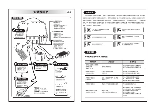
安装说明书
蓄电池管理参数 12V
15.0~17.0V 12.0V
8.0~13.0V 8.0~13.0V 提升充电压-0.2V或-0.4V(胶体) 13.0~15.0V 13.0~15.0V 过放保护电压+0.5V
浮充电压
24V ×2/24V ×2/24V ×2/24V ×2/24V ×2/24V ×2/24V ×2/24V ×2/24V ×2/24V
SDH系列产品参数介绍
产品名称 规格型号
输入电压
输出功率
交流单元参数
输出电压
输出电流
实用蓄电池系统电压
光电池参数
电池板最大输出电压 电池板最大输出电流
恒流源最大输出功率
输出电压
恒流源参数 (一体机)
输出电流 输出纹波 电流精度
典型效率
控制器负载 参数(控制器)
工作模式 输出电流 输出电压 过载保护 短路保护
解决方法
·检查太阳能电池板接线是否正确。 ·断开太阳能电池板连线,重新连接。
·检查LED灯头接线是否正确。 ·断开LED灯头连线,重新连接。
·灯头串数超出控制器的应用范 围,串数过高或过低。请参照 参数表,调整灯头的串并联数。
·降低控制器的输出电流。
·若经常出现此现象,则需要检查 充电是否正常,电池板有无遮挡 等可能影响光伏发电的问题。 ·蓄电池质量存在问题。 ·检查蓄电池连线是否过长,有无虚 接现象。
≤100W
14.5V/12V系统
29V/24V系统
7A12V
3.5A24V
12V
24V
55V
100W100W/24V
12V系统:15~55V; 24V系统:30~55V 150mA~3.3A (可定制至5A)
Eaton UL9540a电池柜顶部电缆套装安装说明书

Installation Instructionsp/n:P-164000934Revision01IMPORTANT SAFETY INSTRUCTIONS SAVE THESE INSTRUCTIONS This manual contains important instructions that should be followed during installation andmaintenance of the UPS system and batteries.Read all instructions before operating the equipmentand save this manual for future reference.CONSIGNES DE SÉCURITÉIMPORTANTES—CONSERVER CES INSTRUCTIONS Ce manuel comporte des instructions importantes que vousêtes invitéàsuivre lors de touteprocédure d'installation et de maintenance des batteries et de l'onduleur.Veuillez consulterentièrement ces instructions avant de faire fonctionner l'équipement et conserver ce manuel afin depouvoir vous y reporter ultérieurement.Eaton reserves the right to change specifications without prior notice.Eaton is a registered trademark of Eaton or its subsidiaries and affiliates.Samsung is a registered trademark of Samsung Electronics Co.,Ltd.VELCRO is a registered trademark of Velcro BVBA.All other trademarks are property of their respective companies.©Copyright2020Eaton,Raleigh,NC,USA.All rights reserved.No part of this document may be reproduced in any way without the express written approval of Eaton.Eaton Top Wiring Kit for UL9540a Battery Cabinet Installation Instructions P-164000934—Rev 011E a t o n T o p W i r i n g K i t f o r U L 9540A B a t t e r y C a b i n e t I n s t a l l a t i o n I n s t r u c t i o n s I n t r o d u c t i o nNOTE Startup and operational checks must be performed by an authorized Eaton CustomerService Engineer,or the warranty terms specified in the uninterrtuptible power supply(UPS)installation and operation manual become void.This service is offered as part ofthe sales contract for the UPS.Contact an Eaton service representative in advance (aminimum two-week notice is required)to reserve a preferred startup date.The Eaton top wiring kit provides an interface between an Eaton UPS and a Samsung®Type S lithium-ion battery cabinet (see Figure 1).The top wiring kit bolts to the top of the Samsung battery cabinet and provides customer landing terminals for DC power,an AC power terminal block for the battery cabinet battery monitoring system (BMS),and a terminal block for dry-contact wiring from the UPS (see Figure 2).Figure 1.Top Wiring KitFigure 2.Top Wiring Kit FeaturesR e f e r e n c e D o c u m e n t sThe following documents are required to complete the installation of the Eaton UPS,Samsung battery cabinet,and top wiring kit:Battery CabinetTop Wiring Kit2Eaton Top Wiring Kit for UL9540a Battery Cabinet Installation Instructions P-164000934—Rev 01•Eaton UPS Installation and Operation Manual –Installation and operation instructions for the Eaton UPS,including site preparation,installation planning,wiring and safety information,and detailed illustrations of the UPS with dimensional and connection point drawings•Part Number P-164000928—LIB System for UPS,Installation Manual –Installation instructions for the battery cabinet,including site preparation,installation planning,wiring and safety information,and detailed illustrations of the battery cabinet with dimensional and connection point drawings•Part number P-164000929—LIB System for UPS,Operation and Maintenance Manual –Operation and maintenance instructions for the battery cabinet Visit /powerquality or contact an Eaton service representative for information on how to obtain copies of these manuals.U s i n g T h i s M a n u a lThis manual describes how to install the top wiring kit.Read and understand the procedures described in this manual,as well as those listed in Reference Documents to ensure trouble-free installation and operation.Read through each procedure before beginning the procedure.Perform only those procedures that apply to the UPS system being installed or operated.C o n v e n t i o n s U s e d i n T h i s M a n u a lThis manual uses these type conventions:•Bold type highlights important concepts in discussions,key terms in procedures,and menu options,or represents a command or option that you type or enter at a prompt.•Italic type highlights notes and new terms where they are defined.IconDescription NoteInformation notes call attention to important features or instructions.[Keys]Brackets are used when referring to a specific key,such as [Enter]or [Ctrl].In this manual,the term UPS refers only to the UPS cabinet and its internal elements.The term UPS systemrefers to the entire power protection system –the UPS cabinet,an external battery system,and options or accessories installed.S ym b ol s ,C o n t r o l s ,a n d I n d i c a t o r sThe following are examples of symbols used on the UPS or accessories to alert you to important information:RISK OF ELECTRIC SHOCK - Observe the warning associated with the risk of electric shock symbol.CAUTION: REFER TO OPERATOR'S MANUAL - Refer to your operator's manual for additional information, such as important operating and maintenance instructions.This symbol indicates that you should not discard the UPS or the UPS batteries in the trash. This product contains sealed, lead‐acid batteries and must be disposed of properly. For more information, contact your local recycling/reuse or hazardous waste center.This symbol indicates that you should not discard waste electrical or electronic equipment (WEEE) in the trash. For proper disposal, contact your local recycling/reuse or hazardous waste center.RISK OF ELECTRIC SHOCK -Observe the warning associated with the risk of electric shock symbol.RISK OF ELECTRIC SHOCK - Observe the warning associated with the risk of electric shock symbol.CAUTION: REFER TO OPERATOR'S MANUAL - Refer to your operator's manual for additional information, such as important operating and maintenance instructions.This symbol indicates that you should not discard the UPS or the UPS batteries in the trash. This product contains sealed, lead‐acid batteries and must be disposed of properly. For more information, contact your local recycling/reuse or hazardous waste center.This symbol indicates that you should not discard waste electrical or electronic equipment (WEEE) in the trash. For proper disposal, contact your local recycling/reuse or hazardous waste center.CAUTION:REFER TO OPERATOR'S MANUAL -Refer to your operator's manual for additional information,such as important operating and maintenance instructions.RISK OF ELECTRIC SHOCK - Observe the warning associated with the risk of electric shock symbol.CAUTION: REFER TO OPERATOR'S MANUAL - Refer to your operator's manual for additional information, such as important operating and maintenanceinstructions.This symbol indicates that you should not discard the UPS or the UPS batteriesin the trash. This product contains sealed, lead‐acid batteries and must be disposed of properly. For more information, contact your local recycling/reuse or hazardous waste center.This symbol indicates that you should not discard waste electrical or electronic equipment (WEEE) in the trash. For proper disposal, contact your local recycling/reuse or hazardous waste center.This symbol indicates that you should not discard waste electrical or electronic equipment (WEEE)inthe trash.For proper disposal,contact your local recycling/reuse or hazardous waste center.IntroductionG e t t i n g H e l pIf help is needed with any of the following:•Scheduling initial startup•Regional locations and telephone numbers•A question about any of the information in this manual•A question this manual does not answerPlease call the Customer Reliability Center at:United States: Canada:All other countries:1-800-843-94331-800-461-9166ext260Call your local service representativePlease use the following e-mail address for manual comments,suggestions,or to report an error in thismanual:****************************S a f e t y W a r n i n g sThe manuals listed in the Reference Documents section contain important instructions that should be followedduring installation and maintenance of the UPS system,top wiring kit,and Type S lithium-ion battery cabinet.Read all instructions before installing or operating the equipment and save the manuals for future reference.The UPS system is designed for industrial or computer room applications,and contains safety shields behindthe door and front panels.However,the UPS system is a sophisticated power system and should be handledwith appropriatecare.This UPS and battery systems contain LETHAL VOLTAGES.All repairs and service should be performed byAUTHORIZED SERVICE PERSONNEL ONLY.There are NO USER SERVICEABLE PARTS inside the UPS orbattery cabinet.Safety WarningsEaton Top Wiring Kit for UL9540a Battery Cabinet Installation Instructions P-164000934—Rev013I n s t a l l a t i o nI n s t a l l a t i o n P l a nRefer to the manuals listed in the Reference Documents section for information on preparing an installationplan for the Eaton UPS and Samsung battery cabinet.In addition to the external wiring recommendations listedin those manuals,see Table1for recommendations specific to the top wiring kit installation.Table1.Customer Wiring Recommendations,Top Wiring KitConnections Recommended Minimum Wire Sizefor75°C Copper Stranded WireRecommended TorqueBattery Wires3/0AWG(2x per pole)519in-lb Ground Wires3/0AWG519in-lb Control Wires(TB1)18AWG5in-lbAC Auxiliary Power(TB2)–See thefollowing note14AWG10in-lbNOTE Each Type S battery system requires a minimum of one three-phase circuit to provideauxiliary power to the battery cabinet BMS.Battery cabinets are configured for400–500Vac or208–220Vac input at the time of order.These circuits must be provided from thecustomer’s electrical distribution and should be protected by a listed15A device(circuitbreaker or fuse),with a recommended wire size of14AWG.Source1(required)isprovided from the UPS output distribution;Source2(optional)is provided from the UPSbypass input.For parallel battery cabinets,the AC sources can be provided to the"master"cabinet top wiring kit and from there to the parallel cabinets using the suppliedinterconnect harnessing.P r e l i m i n a r y I n s t a l l a t i o n I n f o r m a t i o nInstallation should be performed only by qualified personnel knowledgeable of batteries and the requiredprecautions.Observe these precautions while installing the top wiring kit:•Wear the proper electrical and arc flash personal protective equipment(PPE)when voltages of50V or greater are present•Remove watches,rings,or other metal objects•Use tools with insulated handles•Wear rubber gloves and boots•Do not lay tools or metal parts on top of batteries or battery cabinets•Refer to the manuals listed in the Reference Documents section for cabinet dimensions and weight,wiring and terminal data,and installation notesI n s p e c t i n g a n d U n p a c k i n g t h e T o p W i r i n g K i tThe top wiring kit is packed in a shipping carton.1.Carefully inspect the outer packaging for evidence of damage during transit.Installation4Eaton Top Wiring Kit for UL9540a Battery Cabinet Installation Instructions P-164000934—Rev01Eaton Top Wiring Kit for UL9540a Battery Cabinet Installation Instructions P-164000934—Rev 015Do not install a damaged assembly.Report any damage to the carrier and contact your Eaton service representative immediately.2.Open the shipping carton and examine the contents.The carton should contain the items listed in Table 2.If anything is missing,contact your Eaton service representative immediately.3.Remove the top wiring kit,hardware kit,and pack kit from the carton.4.Remove all packaging materials and discard or recycle them in a responsible manner.Table 2.Top Wiring Kit Contents Part Number and Description Qty P-103003825–ASSEMBLY,TOP HAT INTERFACE BOX 1P-152001882–HARNESS,LI-ION TOP WIRING AC POWER 1P-152001883–HARNESS,LI-ION TOP WIRING AC INTERCONNECT 1P-152001884–HARNESS,LI-ION BREAKER AUX INTERCONNECT 1P-174000344–EDGE PROTECTOR,TOP HAT ASSY 1P-103003868–KIT,TOP HAT HARDWARE,CONTAINING:1180190078-107–BOLT HEX HEAD M12X 25180190078-110–BOLT HEX HEAD M12X 35180190109-030–BOLT HEX FL M8X 20180500036-120–WASHER FLAT M12HD 180500037-120–WASHER LK M12CONICAL SPRNG 4841212P-103003579–KIT,UL9540a TOP HAT PACK,CONTAINING:1152201081–TIE WRAP 0.19W X 7.4LG 152104034-037–BUSHING,1.0I.D.152104034-044–BUSHING,0.750I.D.1511P-164000934–Top Wiring Kit Installation Manual (this manual)1P-164000928–SAMSUNG Lithium Ion Battery System UL9540a Configuration Installation Manual 1P-164000929–SAMSUNG Lithium Ion Battery System UL9540a Configuration Operation and Maintenance Manual 1I n s t a l l a t i o n 1.Install the Eaton UPS as directed in the applicable installation and operation manual.2.Install the Samsung battery cabinet as directed up through Section3.9.1,Switchgear and SMPS AssemblyInstallation,of the Samsung battery cabinet installation manual.Do not continue to Section 3.9.2,Battery Module Installation.DO NOT install the battery modules until directed by thisprocedure.NOTE The Samsung battery cabinet door may need to be removed to install the switchgearassembly in the top of the cabinet.The door must be opened more than 90degrees forassembly.Installation6Eaton Top Wiring Kit for UL9540a Battery Cabinet Installation Instructions P-164000934—Rev 013.For a parallel system,repeat Step 2for each battery cabinet in the system.•Install a bushing (part number 152104034–044)between adjacent battery cabinets and route inter-cabinet connections through the bushing (see Figure 3)Figure 3.Install a Bushing Between Adjacent Battery Cabinets in a ParallelSystem4.Remove the seven M5screws along the front and sides of the top wiring kit front cover and loosen thetwo M5screws along the back edge.Remove the front cover (see Figure 4).Figure 4.Remove the Top Wiring Kit Front Cover5.Remove the two DC bus insulators,which are held in place using Velcro®brand fasteners (see Figure 5). Loosen M5 screws (2). Remove front cover.Remove M5 screws (7).InstallationInstallationFigure5.Remove the DC Bus InsulatorsRemove DC bus insulators.6.Remove the M12x40bolts,nuts,and washers that secure the two DC bus bar jumpers,then remove thejumpers(see Figure6).Figure6.Remove the DC Bus Bar JumpersRemove M12 x 40 bolts, washers,and DC bus bar jumpers.7.For a parallel system,remove the circular side cutouts as needed to route control cabling betweenadjacent parallel units(see Figure7).Eaton Top Wiring Kit for UL9540a Battery Cabinet Installation Instructions P-164000934—Rev0178Eaton Top Wiring Kit for UL9540a Battery Cabinet Installation Instructions P-164000934—Rev 01Figure 7.Remove Cutouts as Needed Between Parallel Units8.Place the top wiring kit on the battery cabinet (see Figure 8).Figure 8.Place the Top Wiring Kit on the Samsung Battery Cabinet Remove cutout as neededbetween parallel units.Remove cutout as neededbetween parallel units.InstallationInstallation 9.Install two hex flange M12x20bolts in each mounting tab of the top wiring kit to secure it to the batterycabinet(see Figure9).Figure9.Install Mounting BoltsHex Flange M8 X 20 Bolts10.For a parallel system:a.Repeat Step4through Step9for each top wiring kit in the installation.b.Install a bushing(part number152104034–037)between adjacent top wiring kits(see Figure10).Thebushing can be installed from either side.Figure10.Install a Bushing between Adjacent Top Wiring Kits in a Parallel SystemEaton Top Wiring Kit for UL9540a Battery Cabinet Installation Instructions P-164000934—Rev01910Eaton Top Wiring Kit for UL9540a Battery Cabinet Installation Instructions P-164000934—Rev 0111.Install all power supply and signal connections from the top wiring kit to the battery cabinet.•See Figure 13for wiring between an Eaton 93PM UPS,Samsung battery cabinet,and the top wiring kit.•See Figure 14for wiring between an Eaton 9395or 9395P UPS,Samsung battery cabinet,and the top wiring kit.•Table 3defines the connections for terminal blocks TB1andTB2.NOTEFor terminal block TB1connections to the battery cabinet,use the wire harness provided in the Samsung battery cabinet accessory kit.For terminal block TB2connections to the battery cabinet,use wire harness part number P-152001882provided in the top wiring kit pack kit.12.Install DC link connections from the UPS cabinet to the DC bus bars in the top wiring kit.Secure the two-hole lugs to the DC bus bars using M12x 35bolts,conical washers,and flat washers as shown in Figure 11.Figure 11.Connect UPS DC Link to DC Bus Bars13.For a parallel system:a.Repeat Step 11and Step 12for each top wiring kit and battery cabinet.b.Install all connections between parallel top wiring kits.Route cable harnesses through the inter-cabinet bushing(s)installed in Step 10.NOTEFor inter-cabinet connections to terminal blocks TB1and TB2,use the wire harnesses provided in the top wiring kit pack kit.For TB1connections,use wire harness part number P-152001884;for TB2connections,use wire harness part number P-152001883.14.Refer to the Samsung battery cabinet installation manual and complete Section 3.9.2,Battery ModuleInstallation,and Section 3.9.3,Busbar Installation.For a parallel system,repeat for each battery cabinet in the installation.InstallationEaton Top Wiring Kit for UL9540a Battery Cabinet Installation Instructions P-164000934—Rev 011115.Reinstall the DC bus bar jumpers as shown in Figure 12using the M12bolts,nuts,and washers removedin Step 6.Attach the DC bus bar jumpers to the battery cabinet switchgear terminals using hardware provided in the Samsung battery cabinet accessory kit.Figure 12.Reinstall the DC Bus Bar Jumpers16.Install the DC bus insulators removed in Step 5.17.For a parallel system,repeat Step 15and Step 16for each top wiring kit.18.Refer to the Samsung battery cabinet installation manual and complete the installation starting at Section3.9.4,Module and Switchgear Signal Cable Connection .For a parallel system,repeat for each battery cabinet in the installation.19.Install all customer connections to the top wiring kit.•See Figure 13for wiring between an Eaton 93PM UPS,Samsung battery cabinet,and the top wiring kit.•See Figure 14for wiring between an Eaton 9395or 9395P UPS,Samsung battery cabinet,and the top wiring kit.•Table 3defines the connections for terminal blocks TB1andTB2.NOTEWhen making connections to terminal block TB1,there are six wires from the molded case circuit breaker (MCCB)and dry contact plugs that are not used.Leave the additional wires disconnected,as they are not required for unit operation.Reinstall bus bar jumpers andattach to switchgear terminals.InstallationInstallation20.Reinstall the front cover using the M5screws removed in Step4.For a parallel system,repeat for eachtop wiring kit in the installation.I n i t i a l S t a r t u pStartup and operational checks must be performed by an authorized Eaton Customer Service Engineer,or thewarranty terms specified in the applicable UPS installation and operation manual become void.This service isoffered as part of the sales contract for the UPS.Contact an Eaton service representative in advance(aminimum two-week notice is required)to reserve a preferred startup date.Refer to the manuals listed in Reference Documents for instructions on performing initial startup andoperational checks of the UPS and battery cabinet.W i r i n g D i a g r a m sFigure13.Wiring Diagram,93PM UPS12Eaton Top Wiring Kit for UL9540a Battery Cabinet Installation Instructions P-164000934—Rev01Eaton Top Wiring Kit for UL9540a Battery Cabinet Installation Instructions P-164000934—Rev 0113Figure 14.Wiring Diagram,9395or 9395P UPSInstallationP-16400093401P-16400093401。
变压器安装使用说明书 正文英文)

Part One General首先,感谢您使用本公司的产品!本公司将竭诚为您服务!本说明书是针对本公司生产的110kV级油浸式电力变压器,包括无励磁调压和有载调压、自耦变压器等安装使用中的一些注意事项及有可能出现的现象加以说明。
使用本说明书时,若有疑问或出现本说明书未曾提及的问题请及时与本公司联系,本公司在此表示诚挚的感谢。
第二部分运输及起吊1 运输方式:本公司产品适合公路、铁路、水路等运输方式。
用户可以根据现场实际情况选择运输方式。
2带油运输带油运输的变压器在出厂时充入合格的变压器油,在常温下油面高度离油箱顶约100mm。
变压器运输时应检查有无渗漏现象,特别是箱顶无油部位有无渗漏。
有载调压变压器必须将有载开关内油放至离开关箱顶约100mm,或用专用联通管将变压器油箱与开关油箱联通。
3充氮运输充氮运输的变压器在出厂时充入纯度大于99.9%,露点不高于-40℃的纯氮气。
并在油箱顶上装置充氮设备和压力表。
运输前保持油箱内正压力在0.025~0.03MPa之间,运输过程中压力始终不应低于0.02MPa,否则应及时补气。
4运输装车、固定应严格按照有关运输部门规则执行,并在发运前得到运输部门检验认可。
5主体运输5.1整个运输过程中,(包括铁路、公路、船舶运输)变压器主体倾斜度,长轴方向不大于15°;短轴方向不大于10°。
5.2严禁溜放冲击,运输过程中变压器本体不应有明显位移。
5.3公路运输时,一级公路上速度不超过15km/h,二级公路上速度不超过10km/h。
6主体起吊6.1起吊设备、吊具及装卸地点地基,必须能承受变压器起吊重量(即运输重量),并能满足机械标准中规定的动载荷下必须具备的安全裕度之规定。
6.2起吊时应使用规定的吊攀起吊,并尽可能使每个吊拌同时受力。
吊索与垂直夹角不大于30°;无法满足时应当应采用吊梁起吊。
7主体牵引及起重7.1主体牵引时,牵引点应在变压器重心以下,钢丝绳应挂在下节油箱专用牵引孔上(或用钢丝绳捆绑在变压器油箱上)。
EATON 保险组合电源和 或区域锁定电源断路器的安装说明说明书

Installation Instructions for ND, HND, NDC, CND, CHND, CNDC Circuit Breakers with Digitrip OPTIM Trip Unit and Powernet, and/or Zone InterlockContentsDescription Page1.0 I ntroduction (2)2.0 Installation (3)3.0Manual Operation (5)4.0Inspection and Field Testing (5)2Instruction Leaflet IL29C109JE ective November 2013Installation Instructions for ND, HND, NDC, CND,CHND, CNDC Circuit Breakers with Digitrip OPTIMTrip Unit and Powernet, and/or Zone InterlockEATON CORPORATION CONTACT WITH ENERGIZED EQUIPMENT CANRESULT IN DEATH, SEVERE PERSONAL INJURY, OR SUBSTANTIAL PROPERTY DAMAGE. DO NOT NANCE ON EQUIPMENT WHILE IT IS ENERGIZED.ALWAYS VERIFY THAT NO VOLTAGE IS PRESENT BEFORE PROCEEDING WITH THE TASK, ANDTY PROCEDURES.ATTEMPT TO INSTALL OR PERFORM MAINTE -ALWAYS FOLLOW GENERALLY ACCEPTED SAFE -EATON IS NOT LIABLE FOR THE MISAPPLICATION MISINSTALLATION OF ITS PRODUCTS.The user is cautioned to observe all recommendations, warnings and cautions relating to the safety of person -nel and equipment as well as general and local health and safety laws, codes and procedures.The recommendations and information contained herein are based on Eaton experience and judgment, but should not be considered to be all -inclusive or covering every application or circumstance which may arise. If any que- stions arise, contact Eaton for further information or instructions.Figure 1-1N-Frame OPTIM Series C Circuit BreakerFrame(OPTIM 750,1050shown,the Model 550 has no Side Bracket)1.0INTRODUCTIONGeneral InformationThe N -frame OPTIM Series C circuit breaker (Figure 1-1)types ND, HND, and NDC are 600 VAC maximum rated devices with Digitrip OPTIM Models 550,750 or 1050 trip units rated 800A or 1200A maximum continu -ous current. They are for AC applications only and can be reverse fed. They are listed in accordance with Underwriters Laboratories, Inc. Standard UL 489 and satisfy the requirements of International Electrotechnical Commission Recommendations No. IEC 947-2. OPTIM 750and 1050 N -Frame circuit breakers are equipped with zone interlocking and an auxiliary switch and alarm (signal)/lockout switch for customer usage. Other inter -nal accessories are available but must be factoryinstalled since they are factory sealed. Model 550is not sealed and can accommodate field installed acces -sories, including an IMPACC communications kit.Contact Eaton for the following information and user manuals: N -Frame and Accessories Selection Data 29-120N Instructions and Overview of OPTIMTrip UnitsInstructions on the Operation of DigitripOPTIMIZER Hand Held Programmer Instructions on the Operation of DigitripBreaker Interface ModuleInstructions on the Operation of DigitripOPTIM Trip UnitsDigitrip OPTIM Wiring Diagrams 92a t a D n o i t a c i l p p A -167N 100 Percent Rated N -frame Circuit Breakers CND, CHND, and CNDC circuit breakers are suitable for continuous operation at 100percent of the frame rating in an enclosure which measures at least 42” height, 22.75” width and 11.5” depth. The 800A versionrequires no ventilation. The 1200A version requires 224 sq.in. of ventilation on the front face of the enclosure (72sq.in. top, 72 sq. in. bottom, 40 sq.in. left and 40sq.in. right). The 1200A version has to be used with the supplied conductor extensions and terminal barriers as shown in Figure 2-2. Use only 90°C rated wire withampacity based on 75°C rated conductors. Use Copperonly orterminals only. WARNING3Instruction Leaflet IL29C109JEive November 2013Installation Instructions for ND, HND, NDC, CND,CHND, CNDC Circuit Breakers with Digitrip OPTIMTrip Unit and Powernet, and/or Zone InterlockEATON CORPORATION 2.0INSTALLATIONThe installation procedure consists of inspecting the cir -cuit breaker and, as applicable, installing the rating plug and terminals; mounting the circuit breaker; connecting the line and load conductors; torquing terminals; and attaching terminal covers. Circuit breaker frames, rating plugs, accessories, mounting hardware, and unmounted terminals may be supplied in separate packages. To install the circuit breaker, perform the following steps. Compare nameplate data with existing equipment ratings and system requirements to make sure that the circuit breaker is suitable for the intended installation. Prior to mounting, confirm that the circuit breaker has not been damaged during transit or initial handling. Remove line and load end covers. Mount wire con -necting terminals as shown in Figure 2-1. Secure the terminals to the circuit breaker using two cap screws and lockwashers. Torque to 40 to 50 lb-ft.(54.2to 67.8N. m). With the circuit breaker mounted and before the conductors are installed and conductor clamping screws inserted,the terminal mounting screws may be checked for correct torque.THE VOLTAGES IN ENERGIZED EQUIPMENT CAN CAUSE DEATH OR SEVERE PERSONAL INJURY. BEFORE MOUNTING THE CIRCUIT BREAKER IN AN ELECTRICAL SYSTEM, MAKE SURE THERE IS NO FORMED. SPECIAL ATTENTION SHOULD BE PAID TO REVERSE FEED APPLICATIONS TO ENSURE NO VOLTAGE IS PRESENT.VOLTAGE PRESENT WHERE WORK IS TO BE PER -Depending on the equipment configuration, the cir -cuit breaker can be mounted using different styles of hardware. The following steps describe how to mount the circuit breaker using standard hardware. When special hardware is needed (for example, with the motor operator), the instruction leaflet describ -ing the accessory also describes the special mount -ing arrangements.2-3. To mount the circuit breaker, perform the following steps:a.For individual surface mounting, drill mounting panel using thedrilling plan shown in Figure 2-3. For front cover applications, cut out cover to correct escutcheon dimensions, see Figure 2-4. Make sure accessory wiring is accessible when the circuit breaker is mounted.Figure 2-1Terminal Installationb.Position circuit breaker on mounting surface.c. Install circuit breaker mounting screws and washers.Torque mounting screws to 30-35 Ib -ft. (41-47CAUTIONWHEN ALUMINUM CONDUCTORS ARE USED, THE APPLICATION OF A SUITABLE JOINT COMPOUND IS RECOMMENDED TO REDUCE THE POSSIBILITY OF TERMINAL OVERHEATING. OVERHEATING CAN CAUSE NUISANCE TRIPPING AND DAMAGE TOTHE CIRCUIT BREAKER.Connect line and load conductors and accessoryleads.Install the supplied neutral current sensor in the neutral pole of a four -wire system, see Figure 2-7andwiring diagram 29C894.After the circuit breaker is installed, check allmounting hardware and terminal connecting hardware for correct torque loading. Torque values for line/load terminals are given on thecircuit breaker nameplate. Re -install load end and line end covers and secure with pan head screws provided. Torque large screws to 35-45 Ib -in. (4.0- 5.0and small screws to 24-30in. (2.7- 3.4When using the terminals TA700NB1 or T700NB1,or when prospective fault currents ofcabled installations exceed 65kA (such as NDC applica -tions)the conductors are to be braced in accordancewith Figure 2-5.WARNING2.12.24Instruction Leaflet IL29C109JE ective November 2013Installation Instructions for ND, HND, NDC, CND,CHND, CNDC Circuit Breakers with Digitrip OPTIMTrip Unit and Powernet, and/or Zone InterlockEATON CORPORATIONFigure 2-2Conductor Extensions and Terminal Installation for 100%Rating31831825) Tap4-PlacesBreakerBreaker2-AND 3-4E L O P -POLEFigure 2-3Circuit Breaker Mounting Bolt Drilling Plan Table 2.11I5Instruction Leaflet IL29C109JE ective November 2013Installation Instructions for ND, HND, NDC, CND,CHND, CNDC Circuit Breakers with Digitrip OPTIM Trip Unit and Powernet, and/or Zone InterlockEATON CORPORATION 2 50 R (635R)1$06(4841)Handle188R5 587 (141 91)(8095)6375(161 92)FRONT COVER CUTOUTFigure 2-4Circuit Breaker Escutcheon DimensionsHAZARDOUS VOLTAGE CONDITIONS CAN CAUSE DEATH OR SEVERE PERSONAL INJURY. MAINTAIN AGE SPACINGS AT TERMINATIONS.ORIGINAL ELECTRICAL CLEARANCE AND CREEP-Connect the control wires and power wires to their appropriate locations on the male plug of the terminal block, see Figure 2-6.Control power is necessary if IMPACC communication isrequired.Install an appropriate rating plug, see Table 2.1.2-10.Plug in the hand held Digitrip OPTIMIZER into the programming port and set the INCOM address. Then set the various trip unit current settings using the OPTI -MIZER,or use the Breaker Interface Module when INCOM is available.If IMPACC Series software is part of the system, this too can be used to set the trip unit settings. Refer to the user manuals for details. 3.0MANUAL OPERATIONManual operation of the circuit breaker is controlled by the circuit breaker handle and the PUSH -TO -TRIP but -ton in the trip unit. The circuit breaker handle has three positions,two of which are shown on the cover with raised lettering to indicate ON and OFF. On the handle,ON,OFF,and trip are also shown by a color -coded strip for each circuit breaker handle position: red for ON, white for tripped, and green for OFF (see Figure 3-1).BreakerFigure 2-5Securement of Cable (See caution note for bracing instruction)Circuit Breaker ResetAfter a trip operation, the circuit breaker is reset by mov -ing the handle to the Reset (extreme OFF)position. It is not necessary to press the reset button before resetting the breaker. The reset button affects only the cause of trip indicator and trip information in the trip’s memory. It does not affect the operation of the circuit breaker itself.No circuit breaker should be until the cause of trip is known and the situation rectified. PUSH -TO -TRIP ButtonThe PUSH -TO -TRIP button operates the circuit breaker tripping function and may be used to periodically exer -cise the operating mechanism. The button is designed to be operated by a small screwdriver. 4.0INSPECTION AND FIELD TESTINGSeries C molded case circuit breakers are designed toprovide years of almost maintenance -freeo peration. The following procedure d escribes how to do a limitedamount of field inspection and testing of a circuit breaker. InspectionCircuit breakers in service should be inspected!WARNING6Instruction Leaflet IL29C109JE ective November 2013Installation Instructions for ND, HND, NDC, CND,CHND, CNDC Circuit Breakers with Digitrip OPTIMTrip Unit and Powernet, and/or Zone InterlockEATON CORPORATIONPos.TerminalWire ColorIICK Zone InterlockZone1GF AL GF Alarm X X 2Zone OUTShortOutput 3Zone INShort InputX X X X 4COMCommonInterlockXX XX X 5NEG Black*24V Cont ro I6+24VdcOrange*24Power Supply*Power16Bell N.C.Red Alarm N.C.IIII17ComBlack Common I I I I 18Red Switch N.O.I I I I 19BlueAux Switch N.C.20SpareIIIIIII Pos15AlarmAux.SwitchBLUThe combination Bell Alarm Auxiliary Switch is only available on the OPTIM 1050 units.If damaged,a terminal block cover can be purchased through Eaton. The part number is 4214844699NOTICE1.It is crucial to connect the +24 VDC power supply to the correct terminal. Improper connection can destroy theelectronic protection functions of the circuit breaker. The trip unit imposes a load of 45ma.2. The Optim 550Ground Fault Trip and Ground Fault Alarm units have “NS and NS*”wires. The Non -Ground FaultOptim 550units have no wires.3.Customer wiring connections are made on the removable male plug of the terminal block.4.If the customer requires the interlock feature in their system, then the removal of the jumper betweenpositions 23is required.Breaker is shipped as self interlocked from the factory.Figure 2-6OPTlM Wiring TerminationsBLU7Instruction Leaflet IL29C109JE ective November 2013Installation Instructions for ND, HND, NDC, CND,CHND, CNDC Circuit Breakers with Digitrip OPTIM Trip Unit and Powernet, and/or Zone InterlockEATON CORPORATIONPolarity 75Trapped HolesMarkingsFigure 2-7Neutral Sensor Outlinecally. The inspection should include the following checks 4-1 through 4-7.WARNINGTHE VOLTAGES IN ENERGIZED EQUIPMENT CAN CAUSE SEVERE PERSONAL INJURY OR DEATH. BEFORE INSPECTING THE CIRCUIT BREAKER IN AN ELECTRICAL SYSTEM, MAKE SURE THE CIR -CUIT BREAKER IS SWITCHED TO THE OFF POSI -TION AND THAT THERE IS NO VOLTAGE PRESENT WHERE WORK IS TO BE PERFORMED. SPECIAL ATTENTION SHOULD BE PAID TO REVERSE FEED SENT.APPLICATIONS TO ENSURE NO VOLTAGE IS PRE-CAUTIONSOME COMMERCIAL CLEANING AGENTS WILL DAMAGE THE NAMEPLATES OR MOLDED PARTS. VENTS USED TO CLEAN THE CIRCUIT BREAKER ARE SUITABLE FOR THE JOB.MAKE SURE THAT CLEANING AGENTS OR SOL-Remove dust, dirt, soot, grease, or moisture from the surface of the circuit breaker using a lint -free dry cloth, brush, or vacuum cleaner. Do not blow debris into circuit breaker. If contamination is found, look for the source and eliminate the problem.Red -On White -Trip ColorGreen -Off\IOnFigure 3-1CircuitBreakerSwitch circuit breaker to ON and OFF several times to be sure that the mechanism linkages operate freely and do not bind. If mechanical linkages do not operatefreely, replace circuit breaker.With the circuit breaker in the ON position, press the PUSH -TO -TRIP button to mechanically trip the cir -cuit breaker. Trip, reset, and switch circuit breaker ON several times. If mechanism does not reset each time the circuit breaker istripped, replace the circuit breaker. Check base, cover, operating handle, and handle barrier for cracks, chipping, and discoloration. Circuit breaker should be replaced if cracks or severe discol -oration is found.Check wire connecting terminals and other type bus bar connectors for looseness or signs of overheating.Overheating will show as discoloration, melting, orblistering of conductor insulation, or as pitting or melting of conductor surfaces due to arcing. If there is no evi -dence of overheating or looseness, do not disturb or tighten the connections. If there is evidence of overheat -ing, terminations should be cleaned or replaced. Before re -energizing the circuit breaker, all terminations and cable should be refurbished to the originally installedcondition.Check circuit breaker mounting hardware, and tight -enif necessary.Exposure to certain types of chemicals can cause8Instruction Leaflet IL29C109JE ective November 2013Installation Instructions for ND, HND, NDC, CND,CHND, CNDC Circuit Breakers with Digitrip OPTIMTrip Unit and Powernet, and/or Zone InterlockEATON CORPORATIONdeterioration of electrical connections. Check areawhere circuit breaker is installed for any safety hazards, including personal safety and fire hazards and take required precautionary actions. Field TestingAny field testing should be done in accordance with applicable NEMA Standard. The operation of circuit breakers with Digitrip OPTIM RMS trip units can be field tested periodically using the hand held OPTIMIZER.(See user manuals.)Performance Testing for Ground Fault Trip Units Code RequirementsThe National Electrical Code under Article 230-95-C requires that any ground -fault protection system be per -formance tested when first installed. The test shall be conducted in accordance with approved instructions provided with the equipment. A written record of this test shall be made and shall be available to the authority having inspection j urisdiction. Standards RequirementsAs a follow -up to the basic performance requirements stipulated by the N.E.C.as stated above, UL Standard No. 1053 requires that certain minimum instructionsGROUND FAULT TEST RECORD FORMround Fault Test Records should be Retained by Those in Charge of the Building's lectrical Installation in order to be available to the Authority having Jurisdiction Test DateCircuit Breaker NumberResultsTested Bymust accompany each ground fault protection system. These following statements plus a copy of the test record form illustrated in Figure 4-1are shipped with each Digitrip OPTIM RMS trip unit.General TestThe interconnected system shall be evaluated in accor -dance with the equipment assembler's detailed instruc -tions by qualified personnel.The polarity of the neutral sensor connections (if used)must agree with equipment assembler's detailed instruc -tions to avoid improper operations following apparently correct simulated test operations. Where a questionexists, consult the specifying engineer and/or equipment assembler.The grounding points of the system shall be verified to determine that ground paths do not exist that would bypass the sensors. The use of high -voltage testers and resistance bridges maybe used.WARNINGTHERE IS A HAZARD OF ELECTRICAL SHOCK OR BURN WHENEVER WORKING IN OR AROUND ELECTRICAL EQUIPMENT. ALWAYS TURN OFF DUCTING TESTS.POWER SUPPLYING BREAKER BEFORE CON -SourceNLoadCurrent Limiting Resistor (if required)Figure 4-1Typical Performance Test Record FormFigure 4-2Connections for Ground Fault Trip Test9Instruction Leaflet IL29C109JE ective November 2013Installation Instructions for ND, HND, NDC, CND,CHND, CNDC Circuit Breakers with Digitrip OPTIMTrip Unit and Powernet, and/or Zone InterlockEATON CORPORATION NOTICESince the Digitrip OPTIM RMS trip units derive their operating power from the phase currents, and not from the neutral current, passing current through the neutral sensor only will not properly test the ground fault feature.Using a low -voltage (0-24 volt), high current, ac source,apply a test current of 125%of the Digitrip OPTIM RMS Ground Fault Trip Unit pick -up setting through one phase of the circuit breaker, as shown in Figure 4-2. This should cause the breaker to trip in less than 1sec -ond, and if an alarm indicator is supplied, it should oper -ate. Reset the breaker and the alarm indicator. Repeat the test on the other two phases.If the system is a 4-wire system with a neutral current sensor, apply the same current as described above through one phase of the breaker, returning through the neutral sensor, as shown in Figure 4-3.The breaker should not trip,and the alarm indicator, if supplied, should not operate. Repeat the test on the other two phases.SourceLLowLoadCurrent Limiting Resistor (if required)Figure 4-3Connections for Ground Fault No-Trip Test with a Four- W ire System If the system is a 3-wire system with no neutral current sensor, apply the same current as described above through any two phases of the breaker, with the con -nections exactly as shown in Figure 4-4. The breaker should not trip,and the alarm indicator, if supplied, should not operate. Repeat the test using the other twocombinations of breaker phases.CAUTIONFIELD TESTING SHOULD BE USED FOR FUNC -TIONAL TESTING AND NOT FIELD CALIBRATIONOF THEOPTIM RMS GROUND FAULT TRIP UNIT.ANY TEMPORARY CONNECTION MADE FOR THE PURPOSE OF CONDUCTING TESTS SHOULD BE RESTORED TO PROPER OPERATING CONDITIONS BEFORE RETURNING THE BREAKER TO SERVICE. The results of the test are to be recorded on the test form provided with the equipment.Figure 4-4Connectionsfor Ground Fault No-Trip Testwith a Three-Wire SystemL o wV o l t a g e S o u r c eS o u r c e LCRC u r r e n t L i m i t i n g R e s i s t o r(i f r e q u i r e d )10Instruction Leaflet IL29C109JE ective November 2013Installation Instructions for ND, HND, NDC, CND,CHND, CNDC Circuit Breakers with Digitrip OPTIM Trip Unit and Powernet, and/or Zone InterlockEATON CORPORATION Notes:11Instruction Leaflet IL29C109JE ective November 2013Installation Instructions for ND, HND, NDC, CND,CHND, CNDC Circuit Breakers with Digitrip OPTIM Trip Unit and Powernet, and/or Zone Interlock EATON CORPORATION Notes:Eaton Corporation Electrical Group1000 Cherrington Parkway Moon Township, PA 15108 United States877-ETN-CARE (877-386-2273) © 2011 Eaton CorporationAll Rights ReservedPrinted in USAPublication No. IL29C109J / TBG000684 Part No. 6634C92H09November 2013Eaton is a registered trademark of Eaton Corporation.All other trademarks are property of their respective owners.Instruction Leaflet IL29C109J E ective November 2013Installation Instructions for ND, HND, NDC, CND, CHND, CNDC Circuit Breakers with Digitrip OPTIM Trip Unit and Powernet, and/or Zone InterlockThe instructions for installation, testing, maintenance, or repair herein are provided for the use of the product in general commercial applications and may not be appropriate for use in nuclear applica-tions. Additional instructions may be available upon speci c request to replace, amend, or supplement these instructions to qualify them for use with the product in safety-related applications in a nuclear facility.This Instruction Booklet is published solely for information purposes and should not be considered all-inclusive. If further information is required, you should consult an authorized Eaton sales representa-tive.The sale of the product shown in this literature is subject to the terms and conditions outlined in appropriate Eaton selling policiesor other contractual agreement between the parties. This literatureis not intended to and does not enlarge or add to any such contract. The sole source governing the rights and remedies of any purchaser of this equipment is the contract between the purchaser and Eaton. NO WARRANTIES, EXPRESSED OR IMPLIED, INCLUDING WARRANTIES OF FITNESS FOR A PARTICULAR PURPOSE OR MERCHANTABILITY, OR WARRANTIES ARISING FROM COURSE OF DEALING OR USAGE OF TRADE, ARE MADE REGARDING THE INFORMATION, RECOMMENDATIONS, AND DESCRIPTIONS CONTAINED HEREIN.In no event will Eaton be responsible to the purchaser or user in contract, in tort (including negligence), strict liability or otherwisefor any special, indirect, incidental or consequential damage or loss whatsoever, including but not limited to damage or loss of use of equipment, plant or power system, cost of capital, loss of power, additional expenses in the use of existing power facilities, or claims against the purchaser or user by its customers resulting from theuse of the information, recommendations and description contained herein.。