tut_DE2_sdram_verilog
SDRAM及DDR1、DDR2原理简介及设计规则_20150727

DDR差分时钟优势
All address and control input signals are sampled on the crossing of the positive edge of CK and negative edge of CK. Output (read) data is referenced to the crossings of CK and CK (both directions of crossing). 由于数据是在 CK 的上下沿触収,造成传输周期缩短了一半,因此必须要保证 传输周期的稳定以确保数据的正确传输,这就要求 CK 的上下沿 间距要有精确 的控制。但因为温度、电阻性能的改变等原因,CK上下沿间距可能収生变化, 此时不其反相的 CK#就起到纠正的作用(CK上升快下降慢,CK# 则是上升慢下 降快)。
CS#:Chip select,片选信号,低电平时则该信号连接芯片有效,反之无效
CS# enables (registered LOW) and disables (registered HIGH) the command decoder.
CAS#, RAS#,WE#:Command inputs,命令信号,均为低电平有效
等长规则(一般一对一,多颗SDRAM的情况优先选择T拓扑)
DQ DQM CLK ADDR/CTRL/CMD
尽量等长,以CLK为基 准,控制±200mil
内容
概述 SDRAM简介及设计规则 DDR1简介及设计规则 DDR2简介及设计规则 总结
14
DDR内部结构
CLK为差分信号; 增加了单端DQS; Data Mask为DM;
VDD:Power supply,芯片供电电源
SDRAM——3.3V ±0.3V.
零基础到看懂verilog程序以及调试成功(一步一个脚印)

零基础到看懂verilog程序以及调试成功(一步一个脚印)说来很失败,以前没有特意的去学过FPGA。
呆滞后来有许许多多的应用与自己擦肩而过。
觉得甚是遗憾,这一生我们听了太多的道理,却始终过不好这一世。
期初自己是做模拟的,对MCU之类的编程比较有兴趣,却忽略了FPGA之类。
以前总想着找个时间去学习VHDL。
当时记得看了一个星期书。
果断就放弃了。
觉得那个太肯跌了。
和之前学过的C还是有却别的。
但是还是几年前。
那个时候VERILOG的书比较少。
夏宇闻估计那个时候我也不怎么认识他。
知道这几日。
发现自己掌握的东西太少。
相当有必要来吧verilog搞懂。
好在手上有一黑金的板子。
今天做的工作很近单。
但这仅仅是个开始。
来点亮了一个流水灯。
并在基础上修改来修改去了好几回。
觉得有必要记录下来。
不废话了。
正文:相信大家都觉得quartus比ISE好用吧。
安装过程什么的就不具体说明了。
这个如果有必要的话可以传一篇文档上来。
先建立工程。
每个软件的必要!打开软件。
file->new project rezard之后弹出界面。
点击NEXT。
出现下图第一个是保存的文件夹名称。
第二是新建的文件名。
第三和第二个会自动填写上去的。
然后提示是否创建。
点击是。
点击next,然后再在next!填出如下界面。
这里是设置选用的芯片。
由于自己的黑金石该芯片。
所以选择cyclone II.然后一直点击next直到finish。
然后点击新建填出一个对话框。
选择verilog HDL file 点击OK。
保存之后然后进行编程。
这里我的程序是让流水灯循环点亮。
然后在重复,如此生生不息。
这里是自己的代码。
这里后面每句都解释了。
只要你稍微花点时间。
绝对能看懂,楼主自己也是新手。
对于verilog真的以前不怎么懂的。
但是楼主相信。
只要花了时间。
自己笨就笨点。
大方向对了。
还怕不会成功吗。
另外这里的脚包括了时钟,复位脚还有8个LED。
之后还需要管脚配置!!这个是必须的。
DDR2-SDRAM操作时序规范
注意 : 要谨慎使用此图.此图只是提供了所有可能的状态和状态见转换的控制命令 ,而非全部细节.实际使用过程中可能出现的包括不止一 个簇,激活或禁止片内终结电阻,进入或结束断电状态等情况,这些情况的细节并没有全部列入上面的状态转换图 。
2
Device Operations
DDR2 SDRAM
基本功能
*1 : A13现在保留,以后备用,设置模式寄存器时要设为0。 BA2 和 A14 对于 512Mb DDR2不使用,但对于 1Gb 和2Gb DDR2 SDRAMs使用. A15 保留,以被后用
*2 : WR(自动预充电的写恢复时间 )的最小值由 tCK的最大值决定,而WR最大值由 tCK 最小值决定. WR 的计算方法是看tWR 有几个时钟 周期,如果是小数,则进位为大一的整数(WR[cycles] = tWR(ns)/tCK(ns)). 模式寄存器必须编程为这个值 . 同样的方法用 tRP决定 tDAL.
3
Device Operations
DDR2 SDRAM
上电后的初始化时序图
tCHtCL
CK
/CK
tIS
CKE
ODT
Command
NOP
PRE ALL
EMRS
MRS
PRE ALL
REF
400ns
tRP
tMRD
tMRD
tRP
DLL EN AB LE
DLL RESET
tRFC
REF
tRFC
min. 200 Cycle
Device Operations
DDR2 SDRAM
DDR2 SDRAM 扩展模式寄存器设定
EMRS(1)
扩展模式寄存器(1) 存储着激活或禁止DLL的控制信息, 输出驱动强度, ODT 值的选择 和附加延迟等信息. 扩展寄存器(1)的默认值没有被定义, 因此, 上电之后,扩展模式寄存器 (1)的值必须按正确的步骤来设定 。 写扩展模式寄存器(1)是通过拉低CS, RAS, CAS, WE ,置袄 BA0, 同时控制地址线 A0 ~ A13的状态。 在写扩展模式寄存器(1)之前,DDR2 SDRAM 应该通过将 CKE拉高完成所有簇的预充电。扩展模式寄存器(1)设定命令的命令周 期 (tMRD)必须满足完成对扩展模式寄存器 (1)的写操作。在进行正常操作时,只要所有的簇都已经处于预充电完成状态 ,扩展模式寄存器(1)都可以使 用同一命令重新设定.. A0控制着DLL 激活或禁止。 A1被用于激活数据输出驱动能力为一半 。A3~A5 决定着附加延迟, A2和 A6 用语 ODT 值的选定, A7~A9 用于控制 OCD, A10 被用于禁止 DQS#, A11 被用于 RDQS 的激活。
altera-ddr2-sdram-ip核参数设置及读写时序
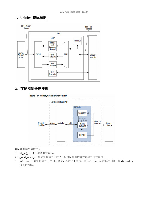
1、Uniphy 整体框图:2、存储控制器连接图PHY的时钟与复位信号1、pll_ref_clk:PLL参考时钟输入。
2、global_reset_n:全局复位信号,对PLL和PHY里的所有逻辑单元进行复位。
3、soft_reset_n:软复位信号,对phy复位,不对PLL复位。
当soft_reset_n为低时,输出的afi_reset_n信号也为低。
3、各个模块间的接口信号3、1控制器与用户接口间使用的Avalon相关信号线:下表是本地接口信号,在altera例化的IP核里,本地用户接口使用的是avalon总线➢Local_addr:指的是用户接口端的地址线,位宽计算方法如下:1)当只使用1pcs 外部存储器时:位宽=bank位宽+行位宽+列位宽-1;2)当使用多片片外存储器时:位宽=芯片位宽+bank位宽+行位宽+列位宽-1;计算位宽时减1 是因为用户数据接口宽度是memory侧数据宽度的两倍(memory侧是在时钟的上升和下降沿都收发数据,而用户侧只在时钟的上升沿收发数据,假如用户读写数据的时钟频率与memory侧的数据频率相同,那么,在时钟上升沿来时,用户侧发送的数据位宽应是memory 侧数据位宽的两倍)。
➢local_be:字节使能信号(用于向控制器写数据时),与memory侧的DM(data mask )信号作用一样,比如,当想使local_data的某8位数据无效,将local_be的对应位置0即可。
➢local_burstbegin:本地突发开始信号,当avalon总线开始突发读写时,将此信号置位‘1’。
(使用条件:本地接口是avalon总线,且memory侧的突发长度大于2)➢local_size:本地突发长度,即连续读或写的local_data个数。
长度不能超过ddr ip核里配置的maximum avalon- mm burst length的长度。
➢local_wdata:本地写数据。
基于FPGA的Verilog语言描述的SDRAM接口电路设计
基于FPGA的SDRAM存储器接口实现摘要随着信息科学的飞速发展,人们面临的信号处理任务越来越繁重,对数据采集处理系统的要求也越来越高。
单片机、DSP等微处理器内部RAM 有限,这就需要在微处理器的外部扩展存储器。
同步动态随机访问存储器具有价格低廉、密度高、数据读写速度快的优点,从而成为数据缓存的首选存储介质,在数据采集系统和图像处理系统等方面中有着重要和广泛的应用。
SDRAM 的读写逻辑复杂,最高时钟频率达100MHz 以上,普通单片机无法实现复杂的SDRAM 控制操作。
复杂可编程逻辑器件CPLD具有编程方便,集成度高,速度快,价格低等优点。
因此选用CPLD 设计SDRAM 接口控制模块, 简化主机对SDRAM 的读写控制。
通过设计基于CPLD 的SDRAM 控制器接口,可以在STM系列、ARM系列、STC系列等单片机和DSP等微处理器的外部连接SDRAM,增加系统的存储空间。
论文开始介绍了SDRAM接口设计研究的背景和研究的目的及意义,引出对SDRAM的研究,详细介绍了SDRAM的基本原理、内部结构、基本操作和工作时序,以及设计的重点及难点。
在这些理论基础上对SDRAM 接口进行模块化设计,了解设计中所使用的硬件和软件。
最后用Verilog语言在软件QuartusⅡ设计CPLD芯片,通过在硬件和软件上的调试基本实现了SDRAM接口的设计。
关键词SDRAM;接口;Verilog;CPLDThe Implementation of SDRAM MemoryInterface Based on the EPM570AbstractWith the rapid development of information science, people face more and more onerous task of signal processing, the requirements of data acquisition and processing system are getting higher and higher. Microprocessor such as single-chip microprocessor, DSP etc, their RAM is limited, which requires external expansion in the microprocessor memory. Synchronous Dynamic Random Access Memory has a low cost, high density, fast read and write data on the merits, thereby becoming the first choice for data cache storage medium, which paly an important role and widely used in the data acquisition system and image processing systems.SDRAM read and write logic is complex, the maximum clock frequency reaches above 100MHz, the ordinary microcontroller can not achieve complex SDRAM control operation. Complex programmable logic device has advantages such as programming convenience, high integrity, high speed and low cost etc. Therefore select CPLD to design control module of SDRAM interface , to simplify the host to read and write control of the SDRAM. Through the design of SDRAM controller interface based on CPLD, you can connect SDRAM in the external of STM series, ARM series, STC series single chip microprocessor and the DSP, increase system storage space.At the beginning of paper introduces the research background, research purpose and significance of the study of SDRAM interface design, leads to the study of SDRAM, detailed introduces information of SDRAM about the basic principles, the internal structure, the basic operation and timing of work, and the design emphasis and difficulty. Based on these theories, modularing the designof SDRAM interface, understanding hardware and software used in the design. Finally, it uses Verilog language in Quartus Ⅱsoftware to design CPLD chip, Through the hardware and the software realization SDRAM the commissioning of the basic design of the interface.Keywords SDRAM; Interface; Verilog; CPLD目录摘要 (I)Abstract (II)第1章绪论 (1)1.1 课题背景 (1)1.2 课题研究的目的及意义 (1)1.3 同步动态随机存储器简介 (2)1.4 论文的结构和框架 (3)第2章SDRAM的工作原理 (4)2.1 存储器的概述 (4)2.1.1 存储器的分类 (4)2.1.2 存储器的技术指标 (5)2.1.3 存储器的比较 (5)2.2 SDRAM的工作原理 (6)2.2.1 SDRAM存储的基本原理 (6)2.2.2 SDRAM的内部结构 (7)2.3 本章小结 (8)第3章SDRAM的基本操作 (9)3.1 SDRAM的基本操作 (9)3.1.1 芯片初始化 (9)3.1.2 行有效 (9)3.1.3 列读写 (10)3.1.4 读操作 (11)3.1.5 写操作 (12)3.2 SDRAM的工作特性 (13)3.2.1 模式寄存器的设置 (13)3.2.2 预充电 (14)3.2.3 刷新 (15)3.3 SDRAM接口设计的要求 (16)3.3.1 存储器接口解决数据存取的难点 (17)3.3.2 存储器接口在工作方式上的初步优化 (17)3.4 本章小结 (18)第4章系统结构及硬件设计 (19)4.1 SDRAM接口设计的整体结构 (19)4.1.1 控制接口模块 (19)4.1.2 CAS延迟模块 (20)4.1.3 突发长度模块 (22)4.1.4 地址转换模块 (22)4.2 EPM570芯片简介 (23)4.2.1 MAXⅡ系列芯片功能简介 (24)4.2.2 逻辑阵列 (25)4.2.3 全局时钟 (25)4.2.4 I/O端口结构 (26)4.3 MT48LC系列芯片简介 (26)4.4 本章小结 (28)第5章软件设计与实现 (30)5.1 利用QuartusⅡ进行设计的流程 (30)5.2 软件的设计 (31)5.2.1 Verilog语言的特点 (31)5.2.2 采用Verilog设计综合的过程 (32)5.2.3 SDRAM接口设计的仿真 (34)5.3 本章小结 (36)结论 (37)致谢 (38)参考文献 (39)附录A (41)附录B (46)附录C (51)第1章绪论1.1课题背景数据采集处理技术是现代信号处理的基础,广泛应用于雷达、声纳、软件无线电、瞬态信号测试等领域。
sdram工作原理

sdram工作原理
SDRAM,即同步动态随机存取存储器(Synchronous Dynamic Random Access Memory),是一种高速存储器。
它的工作原理基于许多相互关联
的电子电路组件,例如纠错代码、行/列地址选择逻辑、内部预取逻辑等。
SDRAM的主要特点是它同步工作。
这意味着SDRAM能够在内存总线时
钟信号的约束下进行工作。
SDRAM存在内部时钟,并在总线时钟的相应边
沿进行数据传输。
这种同步特性使得SDRAM能够以非常高的速度进行数据
传输。
SDRAM还具有被动刷新功能。
因为存储器中的数据不断地流失,因此SDRAM需要定期刷新它的内容以保持数据的正确性。
这个刷新过程可以通
过内部预取逻辑来完成。
即SDRAM会按照预定的规则自动预取一些数据,
以便在它们被访问时能够保持内部各种状态的正确性。
最后,SDRAM支持多通道技术,它能够同时处理多个数据包。
具体而言,SDRAM可以分为若干通道,每个通道可以同时进行一部分数据的读写
操作,从而提高存储器的带宽和吞吐量。
总之,SDRAM是一种高速存储器,它通过同步工作、被动刷新和多通
道技术来实现高效的数据传输和存储。
VHDL工具实现SDRAM控制器的要点分享

VHDL工具实现SDRAM控制器的要点分享在高速实时或者非实时信号处理系统当中,使用大容量存储器实现数据缓存是一个必不可少的环节,也是系统实现中的重点和难点之一。
SDRAM(同步动态随机访问存储器)具有价格低廉、密度高、数据读写速度快的优点,从而成为数据缓存的首选存储介制裁。
但是SDRAM存储体结构与RAM有较大差异,其控制时序和机制也较复杂,限制了SDRAM的使用。
目前,虽然一些能家长微处理器提供了和SDRAM的透明接口,但其可扩展性和灵活性不够,难以满足现实系统的要求,限制了SDRAM的使用。
在详细阐读SDRAM数据文档的前提下,参考ALTERA公司的IP core,利用可编程器件(CPLD,FPGA)设计了一种通用的SDRAM控制器。
它具有很高的灵活性,可以方便地和其它数据采集分析系统中,如图1所示。
在该系统中,以SDRAM存储阵列缓存中频来的高速数据。
存满后,数据被慢速读出至数据处理模块。
下面将对SDRAM控制模块的设计进行详细的描述。
1 SDRAM内存条的结构SDRAM内存条由SDRAM内存芯片构成,根据内存条的容量大小决定内存条上内存芯片的个数。
现以MICRON公司生产的TIM16LSDT6464A型SDRAM内存条为例,简要介绍SDRAM的结构。
MIT16LSDT6464A内存条容量为512M Byte,由16片容量为32M Byte的内存芯片MT46LC32M8A2构成。
16片内存芯片被分为两级,每个芯片的数据位宽为8bit.8片一组,64bit数据宽度。
每个内存芯片的数据线和控制均是复用的。
对内存条的读写操作,是以内存芯片组为单位的,通过内存条的片选信号S0、S1、S2、S3决定组号。
S0、S2控制芯片组1,S1、S3控制芯片组2.SDRAM内存芯片的主要信号有控制信号、控制信号、数据信号,均为工作时钟同步输入、输出信号。
控制信号主要有:CS(片选信号),CKE(时钟使能信号),DQM(输入、输出使能信号),。
altera-ddr2-sdram-ip核参数设置及读写时序(汇编)

1、Uniphy 整体框图:2、存储控制器连接图PHY的时钟与复位信号1、pll_ref_clk:PLL参考时钟输入。
2、global_reset_n:全局复位信号,对PLL和PHY里的所有逻辑单元进行复位。
3、soft_reset_n:软复位信号,对phy复位,不对PLL复位。
当soft_reset_n为低时,输出的afi_reset_n信号也为低。
3、各个模块间的接口信号3、1控制器与用户接口间使用的Avalon相关信号线:下表是本地接口信号,在altera例化的IP核里,本地用户接口使用的是avalon总线 Local_addr:指的是用户接口端的地址线,位宽计算方法如下:1)当只使用1pcs 外部存储器时:位宽=bank位宽+行位宽+列位宽-1;2)当使用多片片外存储器时:位宽=芯片位宽+bank位宽+行位宽+列位宽-1;计算位宽时减1 是因为用户数据接口宽度是memory侧数据宽度的两倍(memory 侧是在时钟的上升和下降沿都收发数据,而用户侧只在时钟的上升沿收发数据,假如用户读写数据的时钟频率与memory侧的数据频率相同,那么,在时钟上升沿来时,用户侧发送的数据位宽应是memory侧数据位宽的两倍)。
local_be:字节使能信号(用于向控制器写数据时),与memory侧的DM(data mask )信号作用一样,比如,当想使local_data的某8位数据无效,将local_be的对应位置0即可。
local_burstbegin:本地突发开始信号,当avalon总线开始突发读写时,将此信号置位‘1’。
(使用条件:本地接口是avalon总线,且memory侧的突发长度大于2)local_size:本地突发长度,即连续读或写的local_data个数。
长度不能超过ddr ip 核里配置的maximum avalon- mm burst length的长度。
local_wdata:本地写数据。
SDRAM控制器软核的Verilog设计

目前,在很多通信芯片及系统的开发中,常常需要用到存储容量大、读写速度高的存储器。
在各种随机存储器件中,SDRAM 的价格低、体积小、速度快、容量大,是比较理想的器件。
但是,与SRAM相比较,SDRAM的控制逻辑复杂,使用很不方便。
为了解决这个矛盾,需要设计专用的SDRAM控制器,使系统用户象使用SRAM一样方便的使用SDRAM 是十分必要的。
考虑到控制器的通用性,本文提出了一种通用的SDRAM控制器的Verilo g设计,并给出了实现结果。
1 SDRAM的工作原理通常一个SDRAM中包含2个或4个BANK,每个BANK的存储单元是按行和列寻址的。
由于这种特殊的存储结构,与SRAM比较而言,SDRAM在工作的原理上有以下几个特点:第一,SDRAM在上电100us-200us 后,必须由一个初始化过程来配置SDRAM的工作模式。
初始化过程是由启动指令流完成:首先由一个Precharge all bank指令完成对所有BANK的预充,然后是两个或多个Auto Refresh指令,最后在模式配置指令下完成SDRAM内部模式设置寄存器的配置。
模式寄存器的值控制着SDRAM的工作方式,详细描述如表1所示。
SDRAM模式寄存器:第二,SDRAM行列地址采用复用的方式减少了地址总线的密度。
这样以来,SDRAM 在每次读写操作时,行列地址要锁存。
具体的,由ACTIVE命令激活要读写BANK,并锁存行地址,然后在读写指令有效时锁存列地址。
第三,SDRAM的操作是通过AP信号的组合指令字完成的。
由于特殊的存储结构,SDRAM操作指令比较多,不像SRAM一样只有简单的读写,其主要的指令字见表2。
2 通用SDRAM控制器的设计2.1 总体设计框图SDRAM控制器的内部结构如图1所示,包括控制寄存器、初始化请求产生、刷新请求产生、指令仲裁器、指令译码、数据通路六个模块。
控制寄存器控制SDRAM的各种工作模式,其值可以通过MCU接口配置。
DE2 Nios II SDRAM调试总结

DE2 Nios II SDRAM调试总结首先定制CPU,由于是对SDRAM读写进行测试,添加了onchip-memory。
(测试正常之后便可重新建立工程在SDRAM中运行程序)DE2平台上的SDRAM时序,要求将DE2所提供的50MHz时钟延迟3ns或者延迟60度之后作为SDRAM的输入时钟(此处延迟3ns即可),可以用锁相环来产生这个时钟延迟。
按下列步骤生锁相环的代码:(1)用Tools>MegaWizard Plug-In Manager菜单建立一个新的Megafunction。
(2)在Installed Plug-Inz中的I/O中选中ALTPLL,并将输入的文件命名为SDRAM_CLK.(3)在向导的第3页中将inclock0的输入频率改为50MHz。
(4)取消向导第4页的所有选项。
(5)将向导第6页中的Clock Phase Shift项设为-3ns,其余参数保持不变,完成生成锁相环的配置。
最后生成的图如下:用来进行测试的程序(书上的参考程序):#include "system.h"#include "altera_avalon_pio_regs.h" int main(){IOWR(SDRAM_BASE,0,3);IOWR_ALTERA_AVALON_PIO_DATA(LED_BASE,IORD(SDRAM_BASE,0));return 0;}编译总是出错:**** Build of configuration Debug for project blank_project_0 **** make -s allCompiling SDRAM.c...../SDRAM.c: In function `main':../SDRAM.c:6: error: `SDRAM' undeclared (first use in this function) ../SDRAM.c:6: error: (Each undeclared identifier is reported only once ../SDRAM.c:6: error: for each function it appears in.)make: *** [obj/SDRAM.o] Error 1Build completed in 182.172 seconds即SDRAM未定义,但CPU中定义的名字是SDRAM。
DDR2 SDRAM仿真分析概要

DDR2 SDRAM仿真分析概要2008-11-28 13:27随着存储器接口的数据速率越来越高,在接收端保证信号完整性和满足时序要求变得更加困难。
尤其是DDR2 SDRAM。
DDR2 SDRAM的数据传输高,延迟和设计容差少,建立时间、保持时间和偏移(Skew)时间都仅有几十皮秒。
本文介绍DDR2 SDRAM设计的简单原理,并讨论如何使用Cadence公司的Allegro工具对DDR2 SDRAM设计进行板级仿真。
DDR SDRAM的出现使传统的同步时钟方式转变成在时钟的上升沿和下降沿同时进行数据采样(图1)。
这种方式能够提供数据的传输速率,但对设计的延迟和时序提出了更严格的要求。
根据Micron公司的资料,数据率为533Mbps的DDR2 SDRAM大约允许585ps左右的板级设计容差。
如果扣除信号完整性和电源完整性的容差后,允许线路延迟的容差仅有30ps左右,因此仅采用数据线等长设计方法已无法符合要求。
图1:DDR SDRAM的源同步方式。
此外,DDR2 SDRAM采用ODT(On-Die Termination)工作模式(图2),即DDR2 SDRAM 内部有终端电阻。
ODT模式在活动状态下启动,在待机状态下关闭,以便降低信号的反射,提高信号质量,降低功耗。
不过,有必要对终端电阻是否适合进行验证。
图2:DDR2 SDRAM的ODT的结构。
DDR设计流程图3为DDR2 SDRAM应用的PCB设计流程,它表明了信号完整性和电源完整性的分析和布局布线之间的关系。
图3:DDR2 SDRAM的PCB设计和仿真流程。
DDR2 SDRAM应用的板级仿真高速电路的板级仿真包括板前仿真和板后仿真两部分。
板前仿真对电路的拓扑结构进行分析,先利用Allegro仿真工具对设计的层叠进行设计来满足阻抗要求,然后对整个电路板的电源噪声问题进行评估,选择合适的去耦电容来稳定电源信号,减少噪声。
对关键网络的拓扑结构采用Allegro SigXp空间解析功能来分析信号反射和串扰的影响,并依据分析的结果,总结相应的设计规则,比如最大导线长度、最大并行线路长度、最小导线间距、导线间的长度误差等设计规则。
零基础学FPGA (二十三) SDR SDRAM(架构篇)

零基础学FPGA (二十三)SDR SDRAM(架构篇)今日我们来讲的是SDRAM的架构以及设计,这也是小墨第一次接触架构,也谈不上给大家讲,就是把我理解的当做一个笔记共享给大家,有什么错误也请乐观指正,究竟我也是没有教师教,也是自己试探的,难免有些不合理的地方。
一、SDRAM 工作部分1、上电初始化我们先来看第一部分,上电初始化。
上电初始化我们知道,上电之后我们需要等待200us的稳定期,这段时光我们可以用一个定时器来计数,这没什么问题,然后进入的是预充电部分,这个时候,预充电的时候,sdram_cmd模块会检测此时的初始化状态机的状态,若处于预充电状态,那么sdram_cmd模块向SDRAM发指令,详细指令sdram的datasheet 里面有,发的是一个precharge,即预充电,发完指令之后,需要等待一段时光,来确保这个指令被SDRAM捕捉,这等待的时光,特权教师用的方式我觉得很好用一个宏定义,当计数器计数到相应的时光后,预充电完成参数置位即end_trp 置位,下面的使用也是一样,即当时始化状态机进入预充电状态i_pre时,计数器开启,开头计数,计数完成,也就是预充电结束的时候,计数器复位,这个复位的控制,可以用case语句来检测初始化状态机的状态,在相应的状态赋予相应的复位与置位接下来是8个自刷新,操作和预充电一样到了模式寄存器的配置阶段,我们需要选定L_bank,以及SDRAM工作模式的配置,当sdram_cmd模块检测到初始化状态机到达模式寄存器配置阶段时,我们的给SDRAM的sdram_bank端口赋相应的值,并且设置地址当时始化结束的时候,标记位init_done置位,告知工作状态机,初始化状态机已经结束,进入工作状态。
下面是我用word做的上电初始化的状态转移图2、自刷新初始化结束之后,SDRAM为了防止数据走失,要举行自刷新,上一篇文章已经讲过了,刷新2^12行需要64ms,也就是每15us刷新一行,也就是我们需要每15us发送一次自刷新哀求给SDRAM工作状态机,状态机一旦检测到自刷新哀求信号,就告知sdram工作模块,然后工作模块就向SDRAM发送自刷新指令,即CMD_A_PEF下面是自刷新的状态转移图3、读写状态初始化结束以后,SDRAM就处于工作状态,每15us举行一次自刷新,这个时候,假如想要读或写数据的话,即向工作状态机sdram_work_FSM 发送读写哀求,假如是读哀求,那么工作状态机进入行有效状态,也即激活状态w_active,此时,sdram_cmd模块会发送行有效指令,即CMD_ACTIVEA同时,我们需要将我们的12位行地址送给我们的sdram地址总线sdram_addr,然后便是一个等待时光段,TRCD,这个时光段里我们是不需要做什么工作的,只需等待TRCD结束TRCD结束的时候,工作状态机进入读状态,此时,我们需要发送列地址选中我们的存储单元,并告知sdram_cmd模块发送读指令,这个过程是读指令和列地址同时发送的。
使用Verilog实现基于FPGA的SDRAM控制器
使用Verilog实现基于FPGA的SDRAM控制器摘要:介绍了SDRAM的特点和工作原理,提出了一种基于FPGA的SDRAM控制器的设计方法,使用该方法实现的控制器可非常方便地对SDRAM进行控制。
关键词:SDRAM;控制器;Verilog;状态机引言--- 在基于FPGA的图象采集显示系统中,常常需要用到大容量、高速度的存储器。
而在各种随机存储器件中,SDRAM的价格低、体积小、速度快、容量大,是比较理想的器件。
但SDRAM的控制逻辑比较复杂,对时序要求也十分严格,使用很不方便,这就要求有一个专门的控制器,使系统用户能很方便地操作SDRAM。
为此,本文提出了一种基于FPGA 的SDRAM控制器的设计方法,并用Verilog给于实现,仿真结果表明通过该方法设计实现的控制器可以在FPGA芯片内组成如图1所示的SDRAM接口,从而使得系统用户对SDRAM的操作非常方便。
SDRAM简介--- SDRAM器件的管脚分为控制信号、地址和数据三类。
通常一个SDRAM中包含几个BANK,每个BANK的存储单元是按行和列寻址的。
由于这种特殊的存储结构,SDRAM有以下几个工作特性。
●SDRAM的初始化--- SDRAM在上电100~200μs后,必须由一个初始化进程来配置SDRAM的模式寄存器,模式寄存器的值决定着SDRAM的工作模式。
●访问存储单元--- 为减少I/O引脚数量,SDRAM复用地址线,所以在读写SDRAM时,先由ACTIVE命令激活要读写的BANK,并锁存行地址,然后在读写指令有效时锁存列地址。
一旦BANK被激活后只有执行一次预充命令后才能再次激活同一BANK。
●刷新和预充--- SDRAM的存储单元可以理解为一个电容,总是倾向于放电,因此必须有定时的刷新周期以避免数据丢失。
刷新周期可由(最小刷新周期÷时钟周期)计算获得。
对BANK预充电或者关闭已激活的BANK,可预充特定BANK也可同时作用于所有BANK,A10、BA0和BA1用于选择BANK。
如何使用DDR2_SDRAM(全集)【范本模板】
如何使用DDR2 SDRAM(一)Elpida Memory Inc。
本文面向使用DDR2 SDRAM进行系统设计的应用工程师,介绍有关现有SDRAM和双倍数据率同步DRAM(DDR SDRAM)的一些知识,如电气工程参数、逻辑电路,以及详细的功能及使用要点,帮助他们了解DDR2 SDRAM的基本功能和使用。
请注意,本文是一个严格意义上的演示指导文件,所出现的数据未经证实,只供大家学习参考。
如果欲了解有关个别产品的详细资料,请参考相关的数据手册。
一、片上端接(ODT)ODT即片上端接,它是一个不久前才增加到DDR2 SDRAM上的新功能。
通过将端接电阻包含於DRAM内,有效地降低了信号的反射。
对於每一个数据I/O,管脚信号(DQ)、差分数据选通信号(DQS and /DQS)、写数据屏蔽信号(RDQS and /RDQS),DRAM控制器能够使用ODT功能同时设定端接电阻的ON和OFF.由於减少了信号的反射(一个主要的噪音源),这个功能可以使信号质量大幅度提高,从而实现比较快速的数据传输。
由於消除了端接电阻的布局和布线工序,ODT功能还简化了系统的设计。
同时,这还意味著主板上元器件数量的减少,降低了与元器件相关的费用。
图1—1。
使用主板端接时的信号反射1.1 信号反射将一个球抛向墙壁将会被反弹回来。
同样地,当电气信号达成传输路径的末尾的时候,将会被反涉回来。
电信号经过阻抗不一致的传输点时,例如总线和DRAM 的连接点,也可能被反射。
信号反射将引起噪声,从而降低信号质量。
高速数据传输系统要求高质量的信号,甚至一些细微的噪声也可能成为一个主要问题。
1.2 主板终接主板终接是一种能够减少信号反射的终接方式,具体方法是将具有适当阻值的电阻器(端接电阻)附著在每一个传输线路的终端.然而,在DDR2 SDRAM的运行频率范围内,这个方法不能充分地减少信号的反射。
另外,在主板上增加端接电阻还增加了元件的数目,并且可能增加成本。
verilog_二进制_fread__概述说明以及解释
verilog 二进制fread 概述说明以及解释1. 引言1.1 概述这篇文章旨在介绍Verilog中的二进制文件读取(fread)方法,并提供相关的概述、解释和应用举例。
通过本文的阅读,读者将能够了解fread函数的使用方法以及它在Verilog中处理二进制文件的实际应用。
1.2 研究背景在现代数字电路设计领域,Verilog已成为一种广泛使用的硬件描述语言。
由于其高效、灵活以及良好的可重复性,Verilog在各种应用场景中得到了广泛运用。
然而,在一些特定的应用中,需要对二进制文件进行读取和处理,这对于硬件工程师来说可能是一个挑战。
1.3 目的本文旨在提供关于Verilog中二进制文件读取(fread)方法的全面说明。
我们将介绍该方法的基本原理和使用方法,并给出具体的示例以加深理解。
同时,我们还会进行实验验证和性能比较,以评估该方法在不同情况下的表现。
最后,我们将总结研究成果并展望未来可能开展的相关工作。
以上是“引言”部分内容。
请您根据需要进行修改和完善。
2. Verilog 二进制文件读取(fread)2.1 Verilog简介Verilog是一种硬件描述语言,用于描述和设计数字电路和系统。
它是一种建模语言,允许设计者通过声明性的方式来描述他们想要实现的功能和行为。
2.2 二进制文件读取概述在Verilog中,二进制文件读取是指从磁盘或其他存储设备中加载二进制数据到Verilog代码中的过程。
这些数据可以包含不同类型的信息,例如图像、音频、视频以及其他任何需要处理的数据。
在进行二进制文件读取之前,需要使用fopen函数来打开一个文件,并将其与一个逻辑文件变量关联起来。
逻辑文件变量用于表示已打开的文件,并作为后续操作的参数。
2.3 fread函数详解fread函数是Verilog中用于从逻辑文件变量中读取二进制数据的函数。
它接受以下参数:- 数据目标:指定将数据读入哪个变量。
- 数据类型:指定要读取的数据类型,如整数、浮点数等。
SDRAM的verilog代码

module sdr_test(clk,rst_n,sdram_clk,sdram_cke,sdram_cs_n,sdram_ras_n,sdram_cas_n,sdram_we_n,sdram_ba,sdram_addr,sdram_data,//sdram_udqm,sdram_ldqmrs232_tx,/* sdram_rd_req,sdram_wr_ack,sdram_rd_ack,sys_data_out,sdram_busy,sys_data_in,sys_dout_rdy,*/ rdf_dout/*,rdf_rdreq*/);input clk; //系统时钟,100MHzinput rst_n; //复位信号,低电平有效// FPGA与SDRAM硬件接口output sdram_clk; // SDRAM时钟信号output sdram_cke; // SDRAM时钟有效信号output sdram_cs_n; // SDRAM片选信号output sdram_ras_n; // SDRAM行地址选通脉冲output sdram_cas_n; // SDRAM列地址选通脉冲output sdram_we_n; // SDRAM写允许位output[1:0] sdram_ba; // SDRAM的L-Bank地址线output[11:0] sdram_addr; // SDRAM地址总线//output sdram_udqm; // SDRAM高字节屏蔽//output sdram_ldqm; // SDRAM低字节屏蔽inout[15:0] sdram_data; // SDRAM数据总线output rs232_tx; //RS232发送数据信号////////////////////////////////////////////////// SDRAM的封装接口测试引出/*output sdram_rd_req; //系统读SDRAM请求信号output sdram_wr_ack; //系统写SDRAM响应信号output sdram_rd_ack; //系统读SDRAM响应信号output[15:0] sys_data_in; //写SDRAM时数据暂存器,4个突发读写字数据,默认为00地址bit15-0;01地址bit31-16;10地址bit47-32;11地址bit63-48output[15:0] sys_data_out; //读SDRAM时数据暂存器,(格式同上)output sdram_busy; // SDRAM忙标志,高表示SDRAM处于工作中output sys_dout_rdy; // SDRAM数据输出完成标志*/output[15:0] rdf_dout; //sdram数据读出缓存FIFO输出数据总线//output rdf_rdreq; //sdram数据读出缓存FIFO数据输出请求,高有效////////////////////////////////////////////////// SDRAM的封装接口wire sdram_wr_req; //系统写SDRAM请求信号wire sdram_rd_req; //系统读SDRAM请求信号wire sdram_wr_ack; //系统写SDRAM响应信号,作为wrFIFO的输出有效信号wire sdram_rd_ack; //系统读SDRAM响应信号,作为rdFIFO的输写有效信号wire[21:0] sys_addr; //读写SDRAM时地址暂存器,(bit21-20)L-Bank地址:(bit19-8)为行地址,(bit7-0)为列地址wire[15:0] sys_data_in; //写SDRAM时数据暂存器wire[15:0] sys_data_out; //sdram数据读出缓存FIFO输入数据总线wire sdram_busy; // SDRAM忙标志,高表示SDRAM处于工作中wire sys_dout_rdy; // SDRAM数据输出完成标志//wrFIFO输入控制接口wire[15:0] wrf_din; //sdram数据写入缓存FIFO输入数据总线wire wrf_wrreq; //sdram数据写入缓存FIFO数据输入请求,高有效//rdFIFO输出控制接口wire[15:0] rdf_dout; //sdram数据读出缓存FIFO输出数据总线wire rdf_rdreq; //sdram数据读出缓存FIFO数据输出请求,高有效//系统控制相关信号接口wire clk_25m; //PLL输出25MHz时钟wire clk_100m; //PLL输出100MHz时钟wire sys_rst_n; //系统复位信号,低有效//------------------------------------------------//例化系统复位信号和PLL控制模块sys_ctrl uut_sysctrl(.clk(clk),.rst_n(rst_n),.sys_rst_n(sys_rst_n),.clk_25m(clk_25m),.clk_100m(clk_100m),.sdram_clk(sdram_clk));//------------------------------------------------//例化SDRAM封装控制模块sdram_top uut_sdramtop( // SDRAM.clk(clk_100m),.rst_n(sys_rst_n),.sdram_wr_req(sdram_wr_req),.sdram_rd_req(sdram_rd_req),.sdram_wr_ack(sdram_wr_ack),.sdram_rd_ack(sdram_rd_ack),.sys_addr(sys_addr),.sys_data_in(sys_data_in),.sys_data_out(sys_data_out),.sys_dout_rdy(sys_dout_rdy),//.sdram_clk(sdram_clk),.sdram_busy(sdram_busy),.sdram_cke(sdram_cke),.sdram_cs_n(sdram_cs_n),.sdram_ras_n(sdram_ras_n),.sdram_cas_n(sdram_cas_n),.sdram_we_n(sdram_we_n),.sdram_ba(sdram_ba),.sdram_addr(sdram_addr),.sdram_data(sdram_data)// .sdram_udqm(sdram_udqm),// .sdram_ldqm(sdram_ldqm));//------------------------------------------------//读写SDRAM数据缓存FIFO模块例化sdfifo_ctrl uut_sdffifoctrl(.clk_25m(clk_25m),.clk_100m(clk_100m),.wrf_din(wrf_din),.wrf_wrreq(wrf_wrreq),.sdram_wr_ack(sdram_wr_ack),//.sys_addr(sys_addr),.sys_data_in(sys_data_in),.sdram_wr_req(sdram_wr_req),.sys_data_out(sys_data_out),.rdf_rdreq(rdf_rdreq),.sdram_rd_ack(sdram_rd_ack),.rdf_dout(rdf_dout),.sdram_rd_req(sdram_rd_req),.syswr_done(syswr_done),.tx_start(tx_start));//------------------------------------------------//例化模拟写入数据到sdram模块wire syswr_done; //所有数据写入sdram完成标志位datagene uut_datagene(.clk(clk_25m),.rst_n(sys_rst_n),.wrf_din(wrf_din),.wrf_wrreq(wrf_wrreq),.moni_addr(sys_addr),.syswr_done(syswr_done),.sdram_rd_ack(sdram_rd_ack));//------------------------------------------------//例化串口数据发送控制模块wire tx_start; //串口发送数据启动标志位,高有效uart_ctrl uut_uartctrl(.clk(clk_25m),.rst_n(sys_rst_n),.tx_data(rdf_dout[7:0]),.tx_start(tx_start), ///////////.fifo232_rdreq(rdf_rdreq),.rs232_tx(rs232_tx));Endmodulemodule datagene(clk,rst_n,wrf_din,wrf_wrreq,moni_addr,syswr_done,sdram_rd_ack);input clk; //FPAG输入时钟信号25MHzinput rst_n; //FPGA输入复位信号//wrFIFO输入控制接口output[15:0] wrf_din; //sdram数据写入缓存FIFO输入数据总线output wrf_wrreq; //sdram数据写入缓存FIFO数据输入请求,高有效output[21:0] moni_addr; //sdram读写地址产生output syswr_done; //所有数据写入sdram完成标志位input sdram_rd_ack; //系统读SDRAM响应信号,作为rdFIFO的输写有效信号,这里捕获它的下降沿作为读地址自增加标志位reg sdr_rdackr1,sdr_rdackr2;//------------------------------------------//捕获sdram_rd_ack下降沿标志位always @(posedge clk or negedge rst_n)if(!rst_n) beginsdr_rdackr1 <= 1'b0;sdr_rdackr2 <= 1'b0;endelse beginsdr_rdackr1 <= sdram_rd_ack;sdr_rdackr2 <= sdr_rdackr1;endwire neg_rdack = ~sdr_rdackr1 & sdr_rdackr2;//------------------------------------------//上电500us延时等待sdram就绪reg[13:0] delay; //500us延时计数器always @(posedge clk or negedge rst_n)if(!rst_n) delay <= 14'd0;else if(delay < 14'd12500) delay <= delay+1'b1;wire delay_done = (delay == 14'd12500); //1ms延时结束//------------------------------------------//每640ns写入8个16bit数据到sdram,//上电后所有地址写入完毕时间需要不到360ms时间reg[5:0] cntwr; //写sdram定时计数器always @(posedge clk or negedge rst_n)if(!rst_n) cntwr <= 6'd0;else if(delay_done) cntwr <= cntwr+1'b1;//------------------------------------------//读写sdram地址产生reg[18:0] addr; //sdram地址寄存器always @(posedge clk or negedge rst_n)if(!rst_n) addr <= 19'd0;else if(!wr_done && cntwr == 6'h3f) addr <= addr+1'b1;//写地址产生else if(wr_done && neg_rdack) addr <= addr+1'b1; //读地址产生////////////testassign moni_addr = {addr,3'b000};reg wr_done; //所有数据写入sdram完成标志位always @(posedge clk or negedge rst_n)if(!rst_n) wr_done <= 1'b0;else if(addr == 19'h7ffff) wr_done <= 1'b1;assign syswr_done = wr_done;//------------------------------------------//写sdram请求信号产生,即wrfifo的写入有效信号reg wrf_wrreqr; //wrfifo的写入有效信号reg[15:0] wrf_dinr; //wrfifo的写入数据always @(posedge clk or negedge rst_n)if(!rst_n) wrf_wrreqr <= 1'b0;else if(!wr_done) begin //上电0.5ms延时完成if(cntwr == 6'h05) wrf_wrreqr <= 1'b1; //写请求信号产生else if(cntwr == 6'h0d) wrf_wrreqr <= 1'b0; //请求信号撤销endalways @(posedge clk or negedge rst_n)if(!rst_n) wrf_dinr <= 16'd0;else if(!wr_done && ((cntwr > 6'h05) && (cntwr <= 6'h0d))) begin //上电0.5ms延时完成wrf_dinr <= wrf_dinr+1'b1; //写入数据递增endassign wrf_wrreq = wrf_wrreqr;assign wrf_din = wrf_dinr;endmodulemodule sdram_ctrl(clk,rst_n,/*sdram_udqm,sdram_ldqm,*/sdram_wr_req,sdram_rd_req,sdram_wr_ack,sdram_rd_ack,sdram_busy,sys_dout_rdy,init_state,work_state,cnt_clk);//系统信号接口input clk; //系统时钟,50MHzinput rst_n; //复位信号,低电平有效// SDRAM硬件接口//output sdram_udqm; // SDRAM高字节屏蔽//output sdram_ldqm; // SDRAM低字节屏蔽// SDRAM封装接口input sdram_wr_req; //系统写SDRAM请求信号input sdram_rd_req; //系统读SDRAM请求信号output sdram_wr_ack; //系统写SDRAM响应信号,作为wrFIFO的输出有效信号output sdram_rd_ack; //系统读SDRAM响应信号//output sdram_ref_w; // SDRAM自刷新请求信号output sdram_busy; // SDRAM忙标志位,高表示忙output sys_dout_rdy; // SDRAM数据输出完成标志// SDRAM内部接口output[4:0] init_state; // SDRAM初始化寄存器output[3:0] work_state; // SDRAM工作状态寄存器output[8:0] cnt_clk; //时钟计数wire done_200us; //上电后200us输入稳定期结束标志位wire sdram_init_done; // SDRAM初始化完成标志,高表示完成wire sdram_busy; // SDRAM忙标志,高表示SDRAM处于工作中reg sdram_ref_req; // SDRAM自刷新请求信号wire sdram_ref_ack; // SDRAM自刷新请求应答信号`include "sdr_para.v" // 包含SDRAM参数定义模块// SDRAM时序延时参数parameter TRP_CLK = 9'd4,//1, //TRP=18ns预充电有效周期TRFC_CLK = 9'd6,//3, //TRC=60ns自动预刷新周期TMRD_CLK = 9'd6,//2, //模式寄存器设置等待时钟周期TRCD_CLK = 9'd2,//1, //TRCD=18ns行选通周期TCL_CLK = 9'd3, //潜伏期TCL_CLK=3个CLK,在初始化模式寄存器中可设置TREAD_CLK = 9'd8, //突发读数据周期256CLKTWRITE_CLK = 9'd8, //突发写数据256CLKTDAL_CLK = 9'd3; //写入等待//------------------------------------------------------------------------------//assign sdram_udqm = 1'b0; // SDRAM数据高字节有效//assign sdram_ldqm = 1'b0; // SDRAM数据低字节有效//------------------------------------------------------------------------------//上电后200us计时,计时时间到,则done_200us=1//------------------------------------------------------------------------------reg[14:0] cnt_200us;always @ (posedge clk or negedge rst_n)if(!rst_n) cnt_200us <= 15'd0;else if(cnt_200us < 15'd20_000) cnt_200us <= cnt_200us+1'b1; //计数assign done_200us = (cnt_200us == 15'd20_000); //条件满足则done_200us=1//------------------------------------------------------------------------------//SDRAM的初始化操作状态机//------------------------------------------------------------------------------reg[4:0] init_state_r; // SDRAM初始化状态always @ (posedge clk or negedge rst_n)if(!rst_n) init_state_r <= `I_NOP;elsecase (init_state_r)`I_NOP: i nit_state_r <= done_200us ? `I_PRE:`I_NOP; //上电复位后200us结束则进入下一状态`I_PRE: init_state_r <= (TRP_CLK == 0) ? `I_AR1:`I_TRP; //预充电状态`I_TRP: init_state_r <= (`end_trp) ? `I_AR1:`I_TRP; //预充电等待TRP_CLK个时钟周期`I_AR1: init_state_r <= (TRFC_CLK == 0) ? `I_AR2:`I_TRF1; //第1次自刷新`I_TRF1: init_state_r <= (`end_trfc) ? `I_AR2:`I_TRF1; //等待第1次自刷新结束,TRFC_CLK个时钟周期`I_AR2: init_state_r <= (TRFC_CLK == 0) ? `I_AR3:`I_TRF2; //第2次自刷新`I_TRF2: init_state_r <= (`end_trfc) ? `I_AR3:`I_TRF2; //等待第2次自刷新结束,TRFC_CLK个时钟周期`I_AR3: init_state_r <= (TRFC_CLK == 0) ? `I_AR4:`I_TRF3; //第3次自刷新`I_TRF3: init_state_r <= (`end_trfc) ? `I_AR4:`I_TRF3; //等待第3次自刷新结束,TRFC_CLK个时钟周期`I_AR4: init_state_r <= (TRFC_CLK == 0) ? `I_AR5:`I_TRF4; //第4次自刷新`I_TRF4: init_state_r <= (`end_trfc) ? `I_AR5:`I_TRF4; //等待第4次自刷新结束,TRFC_CLK个时钟周期`I_AR5: init_state_r <= (TRFC_CLK == 0) ? `I_AR6:`I_TRF5; //第5次自刷新`I_TRF5: init_state_r <= (`end_trfc) ? `I_AR6:`I_TRF5; //等待第5次自刷新结束,TRFC_CLK个时钟周期`I_AR6: init_state_r <= (TRFC_CLK == 0) ? `I_AR7:`I_TRF6; //第6次自刷新`I_TRF6: init_state_r <= (`end_trfc) ? `I_AR7:`I_TRF6; //等待第6次自刷新结束,TRFC_CLK个时钟周期`I_AR7: init_state_r <= (TRFC_CLK == 0) ? `I_AR8:`I_TRF7; //第7次自刷新`I_TRF7: init_state_r <= (`end_trfc) ? `I_AR8:`I_TRF7; //等待第7次自刷新结束,TRFC_CLK个时钟周期`I_AR8: init_state_r <= (TRFC_CLK == 0) ? `I_MRS:`I_TRF8; //第8次自刷新`I_TRF8: init_state_r <= (`end_trfc) ? `I_MRS:`I_TRF8; //等待第8次自刷新结束,TRFC_CLK个时钟周期`I_MRS: init_state_r <= (TMRD_CLK == 0) ? `I_DONE:`I_TMRD;//模式寄存器设置(MRS)`I_TMRD: init_state_r <= (`end_tmrd) ? `I_DONE:`I_TMRD; //等待模式寄存器设置完成,TMRD_CLK个时钟周期`I_DONE: init_state_r <= `I_DONE; // SDRAM的初始化设置完成标志default: init_state_r <= `I_NOP;endcaseassign init_state = init_state_r;assign sdram_init_done = (init_state_r == `I_DONE); // SDRAM初始化完成标志//------------------------------------------------------------------------------//15us计时,每60ms全部4096行存储区进行一次自刷新// ( 存储体中电容的数据有效保存期上限是64ms )//------------------------------------------------------------------------------reg[10:0] cnt_15us; //计数寄存器always @ (posedge clk or negedge rst_n)if(!rst_n) cnt_15us <= 11'd0;else if(cnt_15us < 11'd1499) cnt_15us <= cnt_15us+1'b1; // 60ms(64ms)/4096=15us循环计数else cnt_15us <= 11'd0;always @ (posedge clk or negedge rst_n)if(!rst_n) sdram_ref_req <= 1'b0;else if(cnt_15us == 11'd1498) sdram_ref_req <= 1'b1; //产生自刷新请求else if(sdram_ref_ack) sdram_ref_req <= 1'b0; //已响应自刷新//------------------------------------------------------------------------------//SDRAM的读写以及自刷新操作状态机//------------------------------------------------------------------------------reg[3:0] work_state_r; // SDRAM读写状态reg sys_r_wn; // SDRAM读/写控制信号always @ (posedge clk or negedge rst_n) beginif(!rst_n) work_state_r <= `W_IDLE;elsecase (work_state_r)`W_IDLE: if(sdram_ref_req & sdram_init_done) beginwork_state_r <= `W_AR; //定时自刷新请求sys_r_wn <= 1'b1;endelse if(sdram_wr_req & sdram_init_done) beginwork_state_r <= `W_ACTIVE;//写SDRAMsys_r_wn <= 1'b0;endelse if(sdram_rd_req && sdram_init_done) beginwork_state_r <= `W_ACTIVE;//读SDRAMsys_r_wn <= 1'b1;endelse beginwork_state_r <= `W_IDLE;sys_r_wn <= 1'b1;end//行有效状态`W_ACTIVE: if(TRCD_CLK == 0)if(sys_r_wn) work_state_r <= `W_READ;else work_state_r <= `W_WRITE;else work_state_r <= `W_TRCD;`W_TRCD: if(`end_trcd)if(sys_r_wn) work_state_r <= `W_READ;else work_state_r <= `W_WRITE;else work_state_r <= `W_TRCD;// SDRAM读数据状态`W_READ: work_state_r <= `W_CL;`W_CL: work_state_r <= (`end_tcl) ? `W_RD:`W_CL;`W_RD: work_state_r <= (`end_tread) ? `W_RW AIT:`W_RD; //后面需要添加一个读完成后的预充电等待状态`W_RWAIT: work_state_r <= (`end_trwait) ? `W_IDLE:`W_RWAIT;// SDRAM写数据状态`W_WRITE: work_state_r <= `W_WD;`W_WD: work_state_r <= (`end_twrite) ? `W_TDAL:`W_WD;`W_TDAL: work_state_r <= (`end_tdal) ? `W_IDLE:`W_TDAL;// SDRAM自动刷新状态`W_AR: work_state_r <= (TRFC_CLK == 0) ? `W_IDLE:`W_TRFC;`W_TRFC: work_state_r <= (`end_trfc) ? `W_IDLE:`W_TRFC;default: work_state_r <= `W_IDLE;endcaseendassign work_state = work_state_r; // SDRAM工作状态寄存器assign sdram_busy = (sdram_init_done && work_state_r == `W_IDLE) ? 1'b0:1'b1; // SDRAM忙标志位assign sdram_ref_ack = (work_state_r == `W_AR); // SDRAM自刷新应答信号assign sdram_wr_ack = ((work_state == `W_TRCD) & ~sys_r_wn) | (work_state == `W_WRITE)| ((work_state == `W_WD) & (cnt_clk_r < 9'd6)); //写SDRAM 响应信号,作为wrFIFO的输出有效信号assign sdram_rd_ack = (work_state_r == `W_RD) & (cnt_clk_r > 9'd1) & (cnt_clk_r < 9'd10);//读SDRAM响应信号assign sys_dout_rdy = (work_state_r == `W_RD && `end_tread); // SDRAM数据输出完成标志//------------------------------------------------------------------------------//产生SDRAM时序操作的延时//------------------------------------------------------------------------------reg[8:0] cnt_clk_r; //时钟计数reg cnt_rst_n; //时钟计数复位信号always @ (posedge clk or negedge rst_n)if(!rst_n) cnt_clk_r <= 9'd0; //计数寄存器复位else if(!cnt_rst_n) cnt_clk_r <= 9'd0; //计数寄存器清零else cnt_clk_r <= cnt_clk_r+1'b1; //启动计数延时assign cnt_clk = cnt_clk_r; //计数寄存器引出,内部`define中使用//计数器控制逻辑always @ (init_state_r or work_state_r or cnt_clk_r) begincase (init_state_r)`I_NOP: cnt_rst_n <= 1'b0;`I_PRE: cnt_rst_n <= (TRP_CLK != 0);//预充电延时计数启动`I_TRP: cnt_rst_n <= (`end_trp) ? 1'b0:1'b1; //等待预充电延时计数结束后,清零计数器`I_AR1,`I_AR2,`I_AR3,`I_AR4,`I_AR5,`I_AR6,`I_AR7,`I_AR8:cnt_rst_n <= (TRFC_CLK != 0); //自刷新延时计数启动`I_TRF1,`I_TRF2,`I_TRF3,`I_TRF4,`I_TRF5,`I_TRF6,`I_TRF7,`I_TRF8:cnt_rst_n <= (`end_trfc) ? 1'b0:1'b1; //等待自刷新延时计数结束后,清零计数器`I_MRS: cnt_rst_n <= (TMRD_CLK != 0); //模式寄存器设置延时计数启动`I_TMRD: cnt_rst_n <= (`end_tmrd) ? 1'b0:1'b1; //等待自刷新延时计数结束后,清零计数器`I_DONE:case (work_state_r)`W_IDLE: cnt_rst_n <= 1'b0;`W_ACTIVE: cnt_rst_n <= (TRCD_CLK == 0) ? 1'b0:1'b1;`W_TRCD: cnt_rst_n <= (`end_trcd) ? 1'b0:1'b1;`W_CL: cnt_rst_n <= (`end_tcl) ? 1'b0:1'b1;`W_RD: cnt_rst_n <= (`end_tread) ? 1'b0:1'b1;`W_RWAIT: cnt_rst_n <= (`end_trwait) ? 1'b0:1'b1;`W_WD: cnt_rst_n <= (`end_twrite) ? 1'b0:1'b1;`W_TDAL: cnt_rst_n <= (`end_tdal) ? 1'b0:1'b1;`W_TRFC: cnt_rst_n <= (`end_trfc) ? 1'b0:1'b1;default: cnt_rst_n <= 1'b0;endcasedefault: cnt_rst_n <= 1'b0;endcaseendendmodulemodule sdram_cmd(clk,rst_n,sdram_cke,sdram_cs_n,sdram_ras_n,sdram_cas_n,sdram_we_n,sdram_ba,sdram_addr,sys_addr,init_state,work_state);//系统信号input clk; //50MHzinput rst_n; //低电平复位信号// SDRAM硬件接口output sdram_cke; // SDRAM时钟有效信号output sdram_cs_n; // SDRAM片选信号output sdram_ras_n; // SDRAM行地址选通脉冲output sdram_cas_n; // SDRAM列地址选通脉冲output sdram_we_n; // SDRAM写允许位output[1:0] sdram_ba; // SDRAM的L-Bank地址线output[11:0] sdram_addr; // SDRAM地址总线// SDRAM封装接口input[21:0] sys_addr; // 读写SDRAM时地址暂存器,(bit21-20)L-Bank地址:(bit19-8)为行地址,(bit7-0)为列地址// SDRAM内部接口input[4:0] init_state; // SDRAM初始化状态寄存器input[3:0] work_state; // SDRAM读写状态寄存器`include "sdr_para.v" // 包含SDRAM参数定义模块//-------------------------------------------------------------------------------//-------------------------------------------------------------------------------reg[4:0] sdram_cmd_r; // SDRAM操作命令reg[1:0] sdram_ba_r;reg[11:0] sdram_addr_r;assign {sdram_cke,sdram_cs_n,sdram_ras_n,sdram_cas_n,sdram_we_n} = sdram_cmd_r; assign sdram_ba = sdram_ba_r;assign sdram_addr = sdram_addr_r;//-------------------------------------------------------------------------------//SDRAM命令参数赋值always @ (posedge clk or negedge rst_n) beginif(!rst_n) beginsdram_cmd_r <= `CMD_INIT;sdram_ba_r <= 2'b11;sdram_addr_r <= 12'hfff;endelsecase (init_state)`I_NOP,`I_TRP,`I_TRF1,`I_TRF2,`I_TRF3,`I_TRF4,`I_TRF5,`I_TRF6,`I_TRF7,`I_TRF8,`I _TMRD: beginsdram_cmd_r <= `CMD_NOP;sdram_ba_r <= 2'b11;sdram_addr_r <= 12'hfff;end`I_PRE: beginsdram_cmd_r <= `CMD_PRGE;sdram_ba_r <= 2'b11;sdram_addr_r <= 12'hfff;end`I_AR1,`I_AR2,`I_AR3,`I_AR4,`I_AR5,`I_AR6,`I_AR7,`I_AR8: beginsdram_cmd_r <= `CMD_A_REF;sdram_ba_r <= 2'b11;sdram_addr_r <= 12'hfff;end`I_MRS: begin //模式寄存器设置,可根据实际需要进行设置sdram_cmd_r <= `CMD_LMR;sdram_ba_r <= 2'b00; //操作模式设置sdram_addr_r <= {2'b00, //操作模式设置1'b0, //操作模式设置(这里设置为A9=0,即突发读/突发写)2'b00, //操作模式设置({A8,A7}=00),当前操作为模式寄存器设置3'b011, // CAS潜伏期设置(这里设置为3,{A6,A5,A4}=011)1'b0, //突发传输方式(这里设置为顺序,A3=b0)3'b011 //突发长度(这里设置为8,{A2,A1,A0}=011)};end`I_DONE:case (work_state)`W_IDLE,`W_TRCD,`W_CL,`W_TRFC,`W_RD,`W_WD,`W_TDAL: beginsdram_cmd_r <= `CMD_NOP;sdram_ba_r <= 2'b11;sdram_addr_r <= 12'hfff;end`W_ACTIVE: beginsdram_cmd_r <= `CMD_ACTIVE;sdram_ba_r <= sys_addr[21:20]; //L-Bank地址sdram_addr_r <= sys_addr[19:8]; //行地址end`W_READ: beginsdram_cmd_r <= `CMD_READ;sdram_ba_r <= sys_addr[21:20]; //L-Bank地址sdram_addr_r <= {4'b0100, // A10=1,设置写完成允许预充电sys_addr[7:0] //列地址};end`W_WRITE: beginsdram_cmd_r <= `CMD_WRITE;sdram_ba_r <= sys_addr[21:20]; //L-Bank地址sdram_addr_r <= {4'b0100, // A10=1,设置写完成允许预充电sys_addr[7:0] //列地址};end`W_AR: beginsdram_cmd_r <= `CMD_A_REF;sdram_ba_r <= 2'b11;sdram_addr_r <= 12'hfff;enddefault: beginsdram_cmd_r <= `CMD_NOP;sdram_ba_r <= 2'b11;sdram_addr_r <= 12'hfff;endendcasedefault: beginsdram_cmd_r <= `CMD_NOP;sdram_ba_r <= 2'b11;sdram_addr_r <= 12'hfff;endendcaseendendmodulemodule sdram_wr_data(clk,rst_n,/*sdram_clk,*/sdram_data,sys_data_in,sys_data_out,work_state,cnt_clk);//系统信号input clk; //系统时钟,100MHzinput rst_n; //复位信号,低电平有效// SDRAM硬件接口//output sdram_clk; // SDRAM时钟信号inout[15:0] sdram_data; // SDRAM数据总线// SDRAM封装接口input[15:0] sys_data_in; //写SDRAM时数据暂存器output[15:0] sys_data_out; //读SDRAM时数据暂存器// SDRAM内部接口input[3:0] work_state; //读写SDRAM时数据状态寄存器input[8:0] cnt_clk; //时钟计数`include "sdr_para.v" // 包含SDRAM参数定义模块//assign sdram_clk = ~clk; // SDRAM时钟信号//------------------------------------------------------------------------------//数据写入控制//------------------------------------------------------------------------------reg[15:0] sdr_din; //突发数据写寄存器reg sdr_dlink; // SDRAM数据总线输入输出控制//将待写入数据送到SDRAM数据总线上always @ (posedge clk or negedge rst_n)if(!rst_n) sdr_din <= 16'd0; //突发数据写寄存器复位else if((work_state == `W_WRITE) | (work_state == `W_WD)) sdr_din <= sys_data_in;//连续写入存储在wrFIFO中的256个16bit数据//产生双向数据线方向控制逻辑always @ (posedge clk or negedge rst_n)if(!rst_n) sdr_dlink <= 1'b0;else if((work_state == `W_WRITE) | (work_state == `W_WD)) sdr_dlink <= 1'b1;else sdr_dlink <= 1'b0;assign sdram_data = sdr_dlink ? sdr_din:16'hzzzz;//------------------------------------------------------------------------------//数据读出控制//------------------------------------------------------------------------------reg[15:0] sdr_dout; //突发数据读寄存器//将数据从SDRAM读出always @ (posedge clk or negedge rst_n)if(!rst_n) sdr_dout <= 16'd0; //突发数据读寄存器复位else if((work_state == `W_RD) & (cnt_clk > 9'd0) & (cnt_clk < 9'd10)) sdr_dout <= sdram_data; //连续读出256B的16bit数据存储到rdFIFO中assign sys_data_out = sdr_dout;//------------------------------------------------------------------------------Endmodulemodule sys_ctrl(clk,rst_n,sys_rst_n,clk_25m,clk_100m,sdram_clk);input clk; //FPAG输入时钟信号25MHzinput rst_n; //FPGA输入复位信号output sys_rst_n; //系统复位信号,低有效output clk_25m; //PLL输出25MHz时钟output clk_100m; //PLL输出100MHz时钟output sdram_clk; //用于外部SDAM的时钟100Mwire locked; //PLL输出有效标志位,高表示PLL输出有效//----------------------------------------------//PLL复位信号产生,高有效//异步复位,同步释放wire pll_rst; //PLL复位信号,高有效reg rst_r1,rst_r2;always @(posedge clk or negedge rst_n)if(!rst_n) rst_r1 <= 1'b1;else rst_r1 <= 1'b0;always @(posedge clk or negedge rst_n)if(!rst_n) rst_r2 <= 1'b1;else rst_r2 <= rst_r1;assign pll_rst = rst_r2;//----------------------------------------------//系统复位信号产生,低有效//异步复位,同步释放wire sys_rst_n; //系统复位信号,低有效wire sysrst_nr0;reg sysrst_nr1,sysrst_nr2;assign sysrst_nr0 = rst_n & locked; //系统复位直到PLL有效输出always @(posedge clk_100m or negedge sysrst_nr0)if(!sysrst_nr0) sysrst_nr1 <= 1'b0;else sysrst_nr1 <= 1'b1;always @(posedge clk_100m or negedge sysrst_nr0)if(!sysrst_nr0) sysrst_nr2 <= 1'b0;else sysrst_nr2 <= sysrst_nr1;assign sys_rst_n = sysrst_nr2;//----------------------------------------------//例化PLL产生模块PLL_ctrl uut_PLL_ctrl(.areset(pll_rst), //PLL复位信号,高电平复位.inclk0(clk), //PLL输入时钟,25MHz.c0(clk_25m), //PLL输出25MHz时钟.c1(clk_100m), //PLL输出100MHz时钟.e0(sdram_clk), //用于外部SDAM的时钟100M.locked(locked) //PLL输出有效标志位,高表示PLL输出有效);endmodulemodule uart_ctrl(clk,rst_n,tx_data,tx_start,fifo232_rdreq,rs232_tx);input clk; // 25MHz主时钟input rst_n; //低电平复位信号input[7:0] tx_data; //待发送数据input tx_start; //串口发送数据启动标志位,高有效output fifo232_rdreq; //FIFO读请求信号,高有效output rs232_tx; //RS232发送数据信号//----------------------------------------------------------------//串口发送底层模块和串口波特率选择模块接口wire clk_bps; //发送数据标志位,高有效wire bps_start; //波特率时钟计数器启动信号,高有效//----------------------------------------------------------------//例化串口数据发送底层模块uart_tx uut_tx(.clk(clk),.rst_n(rst_n),.tx_data(tx_data),.tx_start(tx_start),.clk_bps(clk_bps),.rs232_tx(rs232_tx),.bps_start(bps_start),.fifo232_rdreq(fifo232_rdreq));//例化串口数据发送波特率控制模块uart_speed_select uut_ss(.clk(clk),.rst_n(rst_n),.bps_start(bps_start),.clk_bps(clk_bps));Endmodulemodule sdfifo_ctrl(clk_25m,clk_100m,wrf_din,wrf_wrreq,sdram_wr_ack,/*sys_addr,*/sys_data_in,sdram_wr_req,sys_data_out,rdf_rdreq,sdram_rd_ack,rdf_dout,sdram_rd_req,syswr_done,tx_start);input clk_25m; //PLL输出25MHz时钟input clk_100m; //PLL输出100MHz时钟//wrfifoinput[15:0] wrf_din; //sdram数据写入缓存FIFO输入数据总线input wrf_wrreq; //sdram数据写入缓存FIFO数据输入请求,高有效input sdram_wr_ack; //系统写SDRAM响应信号,作为wrFIFO的输出有效信号//output[21:0] sys_addr; //读写SDRAM时地址暂存器,(bit21-20)L-Bank地址:(bit19-8)为行地址,(bit7-0)为列地址output[15:0] sys_data_in; //sdram数据写入缓存FIFO输出数据总线,即写SDRAM时数据暂存器output sdram_wr_req; //系统写SDRAM请求信号//rdfifoinput[15:0] sys_data_out; //sdram数据读出缓存FIFO输入数据总线input rdf_rdreq; //sdram数据读出缓存FIFO数据输出请求,高有效input sdram_rd_ack; //系统读SDRAM响应信号,作为rdFIFO的输写有效信号output[15:0] rdf_dout; //sdram数据读出缓存FIFO输出数据总线output sdram_rd_req; //系统读SDRAM请求信号input syswr_done; //所有数据写入sdram完成标志位output tx_start; //串口发送数据启动标志位,高有效//------------------------------------------------wire[8:0] wrf_use; //sdram数据写入缓存FIFO已用存储空间数量wire[8:0] rdf_use; //sdram数据读出缓存FIFO已用存储空间数量//assign sys_addr = 22'h1a9e21; //测试用assign sdram_wr_req = ((wrf_use >= 9'd8) & ~syswr_done); //FIFO(8个16bit数据)即发出写SDRAM请求信号assign sdram_rd_req = ((rdf_use <= 9'd256) & syswr_done); //sdram写入完成且FIFO半空(256个16bit数据)即发出读SDRAM请求信号assign tx_start = ((rdf_use != 9'd0) & syswr_done); //启动串口发送数据//------------------------------------------------//例化SDRAM写入数据缓存FIFO模块wrfifo uut_wrfifo(.data(wrf_din),.rdclk(clk_100m),.rdreq(sdram_wr_ack),.wrclk(clk_25m),.wrreq(wrf_wrreq),.q(sys_data_in),.wrusedw(wrf_use));//------------------------------------------------//例化SDRAM读出数据缓存FIFO模块rdfifo uut_rdfifo(.data(sys_data_out),.rdclk(clk_25m),.rdreq(rdf_rdreq),.wrclk(clk_100m),.wrreq(/*rdf_wrreq*/sdram_rd_ack),.q(rdf_dout),.wrusedw(rdf_use));endmodule。
基于Verilog HDL的DDR2 SDRAM控制器设计

基于Verilog HDL的DDR2 SDRAM控制器设计周亮;王娟;胡畅华;杨明武;高挺挺【摘要】文章对适用DDR2 SDRAM控制器的结构、接口和时序进行了深入研究与分析,总结出一些控制器的关键技术特性,然后采用了自顶向下(TOP-DOWN)的设计方法,用Verilog硬件描述语言实现控制器,随后在Modelsim 6.1上通过软件功能仿真,用Synopsys公司的DC进行综合,通过Altera公司的FPGA进行硬件验证,结果表明控制器能完全胜任对DDR2 SDRAM的控制.【期刊名称】《合肥工业大学学报(自然科学版)》【年(卷),期】2010(033)008【总页数】4页(P1253-1256)【关键词】DDR2 SDRAM;控制器;Verilog HDL;FPGA【作者】周亮;王娟;胡畅华;杨明武;高挺挺【作者单位】合肥工业大学,电子科学与应用物理学院,安徽,合肥,230009;合肥工业大学,电子科学与应用物理学院,安徽,合肥,230009;合肥工业大学,电子科学与应用物理学院,安徽,合肥,230009;合肥工业大学,电子科学与应用物理学院,安徽,合肥,230009;合肥工业大学,电子科学与应用物理学院,安徽,合肥,230009【正文语种】中文【中图分类】TN430 引言随着处理器性能的不断提高,半导体技术与超大规模集成电路的飞速发展,越来越多的应用将需要更大容量、更高速率的存储器来满足其数据存储的需求,因此高性价比的DDR2存储器将得到越来越广泛的应用,与其相对应的控制器以其灵活的适应性、高可靠性、良好的可复用性必将成为硬件设计的主流。
本文结合FPGA与ASIC 2种设计的长处,提出了一种基于Verilog HDL硬件描述语言的DDR2 SDRAM的控制器设计方法,并且攻克了控制器结构复杂性与流片后芯片验证测试2个难题。
1 DDR2 SDRAM的特点DDR2是由JEDEC定义全新的下一代DDR内存技术标准,是DDR内存的换代产品。
Sdram控制器的Verilog的实现

Sdram控制器的Verilog的实现⽬前,在很多通信芯⽚及系统的开发中,常常需要⽤到存储容量⼤、读写速度⾼的存储器。
在各种随机存储器件中,SDRAM 的价格低、体积⼩、速度快、容量⼤,是⽐较理想的器件。
但是,与SRAM相⽐较,SDRAM的控制逻辑复杂,使⽤很不⽅便。
为了解决这个⽭盾,需要设计专⽤的SDRAM控制器,使系统⽤户象使⽤SRAM⼀样⽅便的使⽤SDRAM是⼗分必要的。
本⽂介绍了SDRAM控制器的Verilog设计,并给出了实现结果。
⼀、 Sdram简介1、 Sdram的接⼝信号2、 Sdram启动和初始化系统商上电后,Sdram 必须经过初始化才能使⽤,初始化过程必须经过以下⼏个步骤:(1)发出NOP指令,等待1ms(2)执⾏PreChargeAll命令(3)执⾏8次AutoRefresh命令(4)设置模式寄存器(Mode Register)(5)等待Tmrd时钟,Sdram就可以正常读写了。
3、 Sdram的模式寄存器Mode Register ⽤于定义Sdram的运⾏模式。
在PC133规范中,Mode Register中包括了突发长度(Burst Length)、突发类型(Burst Type)和CASs延迟(CAS Latency)。
⽤过Mode Register Set 命令进⾏编程,这组信息将会保存知道Sdram掉电为⽌(具体的Mode Register定义和SDRAM的命令看对应Sdram的数据⼿册)。
⼆、 Sdram的命令解析1、 Bank Active 命令在进⾏任何的Read和Write 命令之前,Sdram⾸先要选择进⾏操作的Bank,并且还要打开这个Bank中相应的⾏,这个通过Bank Active 命令来实现,Bank Active打开BA指定的Bank,同时锁存⾏地址信号。
每个Bank 最长激活时间位 Tras,当Bank Active命令执⾏完毕以后,需要进⾏操作的的Bank中的⾏就会被打开,经过Trcd的延时之后,才可以进⾏Read或Write命令。
小梅哥FPGA学习笔记之Quartus II 15.0中仿真DDR2 IP核

小梅哥FPGA学习笔记之Quartus II 15.0中仿真DDR2 IP核虽然近期用不上DDR2的控制器,但是昨天成功仿真Altera 三速以太网IP核又确实让我兴奋了一把,趁着这个兴奋劲儿,再一举拿下DDR2的IP核仿真。
仿真还是在Altera 最新的开发套件Quartus II 15.0中进行。
首先创建工程,我将工程命名为DDR2_SIM,器件选择我比较熟悉的EP4CE10F17C8,仿真工具选择modelsim – altera ,语言为Verilog。
最后,整个工程建立完毕后的Summary如下图所示:工程创建好后,在右侧的IPCatlog中,搜索栏处输入DDR2,然后在搜索结果中选择DDR2 SDRAM Controller with ALTMEMPHY,如下图所示:双击DDR2 SDRAM Controller with ALTMEMPHY,会弹出如下所示的对话框:将该IP命名为DDR2,语言选择Verilog,然后点击OK,就会开始加载参数设置对话框,整个加载过程大约需要等待20到30秒左右才会弹出GUI界面,请大家耐心等待。
弹出的GUI 界面如下所示:很遗憾,整个界面还是显示不全,上半部分无法看到,也无法拖动窗口,原本右下侧的finish和cancel按钮也没有显露出来,这个问题我从使用Quartus II11.0的时候就发现了(没有用过10.x版本,据说是从10.x版本开始出现这个问题的),到了Quartus II 15.0中这个问题依然没有得到解决,还是希望Altera能够尽快修复这个Bug。
虽然界面默认没有完全显示,但是我们还是有办法来让他显示的。
如果你不需要移动这个配置窗口的位置,或者说对界面最上方未显示的部分内容已知或者不关心(实际我们也真的不用去关心)那么简单的解决方法就是单击系统右下角的显示桌面按钮(win7),然后再在任务栏中点击该配置界面,就能够成功加载右下角的finish和cancel按钮了,但是界面上半部分依旧无法看到。
- 1、下载文档前请自行甄别文档内容的完整性,平台不提供额外的编辑、内容补充、找答案等附加服务。
- 2、"仅部分预览"的文档,不可在线预览部分如存在完整性等问题,可反馈申请退款(可完整预览的文档不适用该条件!)。
- 3、如文档侵犯您的权益,请联系客服反馈,我们会尽快为您处理(人工客服工作时间:9:00-18:30)。
Using the SDRAM Memory on Altera’s DE2Board This tutorial explains how the SDRAM chip on Altera’s DE2Development and Education board can be used with a Nios II system implemented by using the Altera SOPC Builder.The discussion is based on the assumption that the reader has access to a DE2board and is familiar with the material in the tutorial Introduction to the Altera SOPC Builder.The screen captures in the tutorial were obtained using the Quartus II version5.1;if other versions of the software are used,some of the images may be slightly different.Contents:Example Nios II SystemThe SDRAM InterfaceUsing the SOPC Builder to Generate the Nios II SystemIntegration of the Nios II System into the Quartus II ProjectUsing a Phase-Locked LoopThe introductory tutorial Introduction to the Altera SOPC Builder explains how the memory in the Cyclone II FPGA chip can be used in the context of a simple Nios II system.For practical applications it is necessary to have a much larger memory.The Altera DE2board contains an SDRAM chip that can store8Mbytes of data.This memory is organized as1M x16bits x4banks.The SDRAM chip requires careful timing control.To provide access to the SDRAM chip,the SOPC Builder implements an SDRAM Controller circuit.This circuit generates the signals needed to deal with the SDRAM chip.1Example Nios II SystemAs an illustrative example,we will add the SDRAM to the Nios II system described in the Introduction to the Altera SOPC Builder tutorial.Figure1gives the block diagram of our example system.Figure1.Example Nios II system implemented on the DE2board.The system realizes a trivial task.Eight toggle switches on the DE2board,SW7−0,are used to turn on or off the eight green LEDs,LEDG7−0.The switches are connected to the Nios II system by means of a parallel I/Ointerface configured to act as an input port.The LEDs are driven by the signals from another parallel I/O interface configured to act as an output port.To achieve the desired operation,the eight-bit pattern corresponding to the state of the switches has to be sent to the output port to activate the LEDs.This will be done by having the Nios II processor execute an application program.Continuous operation is required,such that as the switches are toggled the lights change accordingly.The introductory tutorial showed how we can use the SOPC Builder to design the hardware needed to imple-ment this task,assuming that the application program which reads the state of the toggle switches and sets the green LEDs accordingly is loaded into a memory block in the FPGA chip.In this tutorial,we will explain how the SDRAM chip on the DE2board can be included in the system in Figure1,so that our application program can be run from the SDRAM rather than from the on-chip memory.Doing this tutorial,the reader will learn about:•Using the SOPC Builder to include an SDRAM interface for a Nios II-based system•Timing issues with respect to the SDRAM on the DE2board•Using a phase-locked loop(PLL)to control the clock timing2The SDRAM InterfaceThe SDRAM chip on the DE2board has the capacity of64Mbits(8Mbytes).It is organized as1M x16bits x 4banks.The signals needed to communicate with this chip are shown in Figure2.All of the signals,except the clock,can be provided by the SDRAM Controller that can be generated by using the SOPC Builder.The clock signal is provided separately.It has to meet the clock-skew requirements as explained in section5.Note that some signals are active low,which is denoted by the suffix N.ClockFigure2.The SDRAM signals.3Using the SOPC Builder to Generate the Nios II SystemOur starting point will be the Nios II system discussed in the Introduction to the Altera SOPC Builder tutorial, which we implemented in a project called lights.We specified the system shown in Figure3.Figure3.The Nios II system defined in the introductory tutorial.If you saved the lights project,then open this project in the Quartus II software and then open the SOPC Builder.Otherwise,you need to create and implement the project,as explained in the introductory tutorial,to obtain the system shown in thefigure.To add the SDRAM,in the window of Figure3select Avalon Components>Memory>SDRAM Con-troller and click Add.A window depicted in Figure4appears.Set the Data Width parameter to16bits and leave the default values for the rest.Since we will not simulate the system in this tutorial,do not select the option Include a functional memory model in the system testbench.Click Finish.Now,in the window of Figure3, there will be an sdram_0module added to the design.Since there is only one SDRAM on the DE2board,change the name of this module to simply sdram.Then,the expanded system is defined as indicated in Figure5.Observe that the SOPC Builder assigned the base address0x00800000to the SDRAM.Leave the addresses of all modules as assigned in thefigure and regenerate the system.Figure4.Add the SDRAM Controller.Figure5.The expanded Nios II system.The augmented Verilog module generated by the SOPC Builder is in thefile nios_system.v in the directory of the project.Figure6depicts the portion of the code that defines the input and output signals for the mod-ule nios_system.As in our initial system that we developed in the introductory tutorial,the8-bit vector that is the input to the parallel port Switches is called in_port_to_the_Switches.The8-bit output vector is called out_port_from_the_LEDs.The clock and reset signals are called clk and reset_n,respectively.A new module, called sdram,is included.It involves the signals indicated in Figure2.For example,the address lines are re-ferred to as the output vector zs_addr_from_the_sdram[11:0].The data lines are referred to as the inout vector zs_dq_to_and_from_the_sdram[15:0].This is a vector of the inout type because the data lines are bidirectional.Figure6.A part of the generated Verilog module.4Integration of the Nios II System into the Quartus II ProjectNow,we have to instantiate the expanded Nios II system in the top-level Verilog module,as we have done in the tutorial Introduction to the Altera SOPC Builder.The module is named lights,because this is the name of the top-level design entity in our Quartus II project.Afirst attempt at creating the new module is presented in Figure7.The input and output ports of the mod-ule use the pin names for the50-MHz clock,CLOCK_50,pushbutton switches,KEY,toggle switches,SW,and green LEDs,LEDG,as used in our original design.They also use the pin names DRAM_CLK,DRAM_CKE_N, DRAM_ADDR,DRAM_BA_1,DRAM_BA_0,DRAM_CS_N,DRAM_CAS_N,DRAM_RAS_N,DRAM_WE_N, DRAM_DQ,DRAM_UDQM,and DRAM_LDQM,which correspond to the SDRAM signals indicated in Figure2. All of these names are those specified in the DE2User Manual,which allows us to make the pin assignments by importing them from thefile called DE2_pin_assignments.csv in the directory DE2_tutorials\design_files,which is included on the CD-ROM that accompanies the DE2board and can also be found on Altera’s DE2web pages.Observe that the two Bank Address signals are treated by the SOPC Builder as a two-bit vector called zs_ba_from_the_sdram[1:0],as seen in Figure6.However,in the DE2_pin_assignments.csvfile these signals are given as scalars DRAM_BA_1and DRAM_BA_0.Therefore,in our Verilog module,we concatenated these signals as{DRAM_BA_1,DRAM_BA_0}.Similarly,the vector zs_dqm_from_the_sdram[1:0]corresponds to {DRAM_UDQM,DRAM_LDQM}.Finally,note that we tried an obvious approach of using the50-MHz system clock,CLOCK_50,as the clock signal,DRAM_CLK,for the SDRAM chip.This is specified by the assign statement in the code.This approach leads to a potential timing problem caused by the clock skew on the DE2board,which can befixed as explained in section5.//Implements the augmented Nios II system for the DE2board.//Inputs:SW7−0are parallel port inputs to the Nios II system.//CLOCK_50is the system clock.//KEY0is the active-low system reset.//Outputs:LEDG7−0are parallel port outputs from the Nios II system.//SDRAM ports correspond to the signals in Figure2;their names are those//used in the DE2User Manual.module lights(SW,KEY,CLOCK_50,LEDG,DRAM_CLK,DRAM_CKE_N,DRAM_ADDR,DRAM_BA_1,DRAM_BA_0,DRAM_CS_N,DRAM_CAS_N,DRAM_RAS_N,DRAM_WE_N,DRAM_DQ,DRAM_UDQM,DRAM_LDQM);input[7:0]SW;input[0:0]KEY;input CLOCK_50;output[7:0]LEDG;output[11:0]DRAM_ADDR;output DRAM_BA_1,DRAM_BA_0,DRAM_CAS_N,DRAM_RAS_N,DRAM_CLK;output DRAM_CKE,DRAM_CS_N,DRAM_WE_N,DRAM_UDQM,DRAM_LDQM;inout[15:0]DRAM_DQ;//Instantiate the Nios II system module generated by the SOPC Buildernios_system NiosII(CLOCK_50,KEY[0],LEDG,SW,DRAM_ADDR,{DRAM_BA_1,DRAM_BA_0},DRAM_CAS_N,DRAM_CKE,DRAM_CS_N,DRAM_DQ,{DRAM_UDQM,DRAM_LDQM},DRAM_RAS_N,DRAM_WE_N);assign DRAM_CLK=CLOCK_50;endmoduleFigure7.Afirst attempt at instantiating the expanded Nios II system.As an experiment,you can enter the code in Figure7into afile called lights.v.Add thisfile and all the*.v files produced by the SOPC Builder to your Quartus II pile the code and download the design into the Cyclone II FPGA on the e the application program from the tutorial Introduction to the Altera SOPC Builder,which is shown in Figure8..include"nios_macros.s".equ Switches,0x00001800.equ LEDs,0x00001810GFUNC_startmovia r2,Switchesmovia r3,LEDsloop:ldbio r4,0(r2)stbio r4,0(r3)br loopBREAKFigure8.Assembly language code to control the lights.Use the Nios II Debug Client,which is described in the tutorial Nios II Debug Client,to assemble,download, and run this application program.If successful,the lights on the DE2board will respond to the operation of the toggle switches.Due to the clock skew problem mentioned above,the Nios II processor may be unable to properly access the SDRAM chip.A possible indication of this may be given by the Nios II Debug Client,which may display the message depicted in Figure9.To solve the problem,it is necessary to modify the design as indicated in the next section.Figure9.An error message.5Using a Phase-Locked LoopThe clock skew depends on physical characteristics of the DE2board.For proper operation of the SDRAM chip, it is necessary that its clock signal,DRAM_CLK,leads the Nios II system clock,CLOCK_50,by3nanoseconds. This can be accomplished by using a phase-locked loop(PLL)circuit.There exists a Quartus II Megafunction, called ALTPLL,which can be used to generate the desired circuit.The circuit can be created,by using the Quartus II MegaWizard Plug-In Manager,as follows:1.Select Tools>MegaWizard Plug-In Manager.This leads to the window in Figure10.Choose the actionCreate a new custom megafunction variation and click Next.Figure10.The MegaWizard.2.In the window in Figure11,specify that Cyclone II is the device family used and that the circuit should bedefined in Verilog HDL.Also,specify that the generated output(Verilog)file should be called sdram_pll.v.From the list of megafunctions in the left box select I/O>ALTPLL.Click Next.Figure11.Select the megafunction and name the outputfile.3.In Figure12,specify that the frequency of the inclock0input is50MHz.Leave the other parameters asgiven by default.Click Next to reach the window in Figure13.Figure12.Define the clock frequency.Figure13.Remove unnecessary signals.4.We are interested only in the input signal inclock0and the output signal c0.Remove the other two signalsshown in the block diagram in thefigure by de-selecting the optional input areset as well as the locked output,as indicated in thefigure.Click Next on this page as well as on page5,until you reach page6which is shown in Figure14.Figure14.Specify the phase shift.5.The shifted clock signal is called c0.Specify that a phase shift of−3ns is required,as indicated in thefigure.Click Finish,which advances to page9.6.In the summary window in Figure15click Finish to complete the process.Figure15.The summary page.The desired PLL circuit is now defined as a Verilog module in thefile sdram_pll.v,which is placed in the project directory.Add thisfile to the lights project.Figure16shows the module ports,consisting of signals inclk0 and c0.Figure16.The generated PLL module.Next,we have tofix the top-level Verilog module,given in Figure7,to include the PLL circuit.The desired code is shown in Figure17.The PLL circuit connects the shifted clock output c0to the pin DRAM_CLK.//Implements the augmented Nios II system for the DE2board.//Inputs:SW7−0are parallel port inputs to the Nios II system.//CLOCK_50is the system clock.//KEY0is the active-low system reset.//Outputs:LEDG7−0are parallel port outputs from the Nios II system.//SDRAM ports correspond to the signals in Figure2;their names are those//used in the DE2User Manual.module lights(SW,KEY,CLOCK_50,LEDG,DRAM_CLK,DRAM_CKE_N,DRAM_ADDR,DRAM_BA_1,DRAM_BA_0,DRAM_CS_N,DRAM_CAS_N,DRAM_RAS_N,DRAM_WE_N,DRAM_DQ,DRAM_UDQM,DRAM_LDQM);input[7:0]SW;input[0:0]KEY;input CLOCK_50;output[7:0]LEDG;output[11:0]DRAM_ADDR;output DRAM_BA_1,DRAM_BA_0,DRAM_CAS_N,DRAM_RAS_N,DRAM_CLK;output DRAM_CKE,DRAM_CS_N,DRAM_WE_N,DRAM_UDQM,DRAM_LDQM;inout[15:0]DRAM_DQ;//Instantiate the Nios II system module generated by the SOPC Buildernios_system NiosII(CLOCK_50,KEY[0],LEDG,SW,DRAM_ADDR,{DRAM_BA_1,DRAM_BA_0},DRAM_CAS_N,DRAM_CKE,DRAM_CS_N,DRAM_DQ,{DRAM_UDQM,DRAM_LDQM},DRAM_RAS_N,DRAM_WE_N);//Instantiate the module sdram_pll(inclk0,c0)sdram_pll neg_3ns(CLOCK_50,DRAM_CLK);endmoduleFigure17.Proper instantiation of the expanded Nios II system.Compile the code and download the design into the Cyclone II FPGA on the e the application program in Figure8to test the circuit.Copyright c 2006Altera Corporation.All rights reserved.Altera,The Programmable Solutions Company,the stylized Altera logo,specific device designations,and all other words and logos that are identified as trademarks and/or service marks are,unless noted otherwise,the trademarks and service marks of Altera Corporation in the U.S.and other countries.All other product or service names are the property of their respective holders. Altera products are protected under numerous U.S.and foreign patents and pending applications,mask work rights,and copyrights.Altera warrants performance of its semiconductor products to current specifications in accordance with Altera’s standard warranty,but reserves the right to make changes to any products and services at any time without notice.Altera assumes no responsibility or liability arising out of the application or use of any information,product,or service described herein except as expressly agreed to in writing by Altera Corporation. Altera customers are advised to obtain the latest version of device specifications before relying on any published information and before placing orders for products or services.This document is being provided on an“as-is”basis and as an accommodation and therefore all warranties,rep-resentations or guarantees of any kind(whether express,implied or statutory)including,without limitation,war-ranties of merchantability,non-infringement,orfitness for a particular purpose,are specifically disclaimed.。
