FPC150A075中文资料
低中高压瓷片陶瓷电容器资料规格书
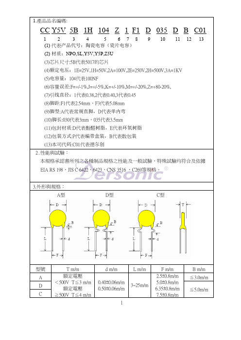
4.0
9.0
5.0 / 7.5
4.0
10.0
5.0 / 7.5
4.0
11.0
5.0 / 7.5
4.0
12.0
5.0 / 7.5
4.0
13.0
5.0 / 7.5
4.0
14.0
5.0 / 7.5
4.0
15.0
5.0 / 7.5
4.0
16.0
5.0 / 7.5
4.0
17.0
5.0 / 7.5
4.0
6.0
5.0 / 7.5
3. Stable capacitance change over the specified temperature.
Product Type
3. ( S - C ) 682PF ~ 224PF measured at 1KHz±10%, 0.1V rms, 25℃
Temp. Range
- 25 ℃ to + 85 ℃
Taping (Radial) -- Lead Spaciபைடு நூலகம்g F = 2.5 / 5.0 / 6.35 / 7.5 ± 0.8
D
s
s
D
H1 Ho
I
P P2
P1
Do Po
b
F
W2 d
W1 Wo w
t
P H1
P2 P1 Ho
Do
I
Po
W2 W1 Wo
s
s
F
d w
t
H1 Ho
I
Straoghe
≦7.0%
≦7.0%
+22% ~ -56% +22% ~ -82%
ZXDU58_W121(V1.0)30A系列组合电源用户手册
3. 《ZXD1500(V4.0)30A 开关整流器用户手册》
该手册介绍 ZXD1500(V4.0)整流器的功能特点、性能参数、工作原理、 外形结构、安装调试、使用操作、日常维护和运输存储。本手册适用于安 装人员和操作维护人员。
请在安装、操作和维护前仔细阅读以上手册,并注意设备上的各种警示牌及警示 语句。所有的随机资料阅读完毕后请妥善保存,以便日后查阅。
ACS750LCA-075中文资料

NOTE: For detailed information on purchasing options, contact your local Allegro field applications engineer or sales representative.Allegro MicroSystems, Inc. reserves the right to make, from time to time, revisions to the anticipated product life cycle plan for a product to accommodate changes in production capabilities, alternative product availabilities, or market demand. The information included herein is believed to be accurate and reliable. However, Allegro MicroSystems, Inc. assumes no respon-sibility for its use; nor for any infringements of patents or other rights of third parties which may result from its use.Recommended Substitutions:For existing customer transition, and for new customers or new appli-cations, refer to the ACS756.Fully Integrated, Hall Effect-Based Linear Current Sensorwith High V oltage Isolation and a Low-Resistance Current ConductorACS750xCA-075Date of status change: November 1, 2008These parts are no longer in production The device should not bepurchased for new design applications. Samples are no longer available.Discontinued ProductACS750xCA-75Selection GuidePart Number T OP (°C)Primary Sensed Current, I P(A)Sensitivity Sens (Typ.)(mV/A)Packing 1ACS750LCA-0752–40 to 150±7519.75170 pieces per bulk bag ACS750SCA-0752–20 to 85±7519.75170 pieces per bulk bag1Contact Allegro for additional packing options.2Variant is in production but has been determined to be LAST TIME BUY . This classification indicates that the variant is obsolete and noticehas been given. Sale of the variant is currently restricted to existing customer applications. The variant should not be purchased for new de-sign applications because of obsolescence in the near future. Samples are no longer available. Status date change: April 28, 2008. Deadline for receipt of LAST TIME BUY orders is October 31, 2008.5× overcurrent conditions. The terminals of the conductive path are electrically isolated from the sensor leads (pins 1 through 3). This allows the ACS75x family of sensors to be used in applications requiring electrical isolation without the use of opto-isolators or other costly isolation techniques.The device is fully calibrated prior to shipment from the factory. The ACS75x family is lead (Pb) free. All pins are coated with 100% matte tin, and there is no lead inside the package. The heavy gauge leadframe is made of oxygen-free copper.Description (continued)Absolute Maximum RatingsCharacteristicSymbol NotesRating Units Supply Voltage V CC 16V Reverse Supply Voltage V RCC –16V Output VoltageV IOUT 16V Reverse Output VoltageV RIOUT –0.1V Maximum Basic Isolation Voltage V ISO 353 VAC, 500 VDC, or V pkV Maximum Rated Input Current I IN 100A Output Current Source I OUT(Source) 3mA Output Current SinkI OUT(Sink)10mA Nominal Operating Ambient Temperature T A Range L –40 to 150ºC Range S–20 to 85ºC Maximum Junction T J (max)165ºC Storage TemperatureT stg–65 to 170ºCTÜV AmericaCertificate Number:U8V 04 11 54214 001Fire and Electric Shock EN60950-1:2001IP+IP–VIOUT GND VCCFunctional Block DiagramPin-out Diagram0.1 μFTerminal List TableNumberName Description1VCC Device power supply pin 2GND Signal ground pin 3VIOUT Analog output signal pin4IP+Terminal for current being sensed 5IP–Terminal for current being sensedELECTRICAL CHARACTERISTICS, over temperature range unless otherwise indicatedCharacteristic Symbol Test Conditions Min.Typ.Max.Units Primary Sensed Current I P–75–75A Supply Voltage V CC 4.5 5.0 5.5V Supply Current I CC V CC = 5.0 V, output open–710mA Output Resistance R OUT I OUT = 1.2 mA–12ΩOutput Capacitance Load C LOAD VOUT to GND––10nF Output Resistive Load R LOAD VOUT to GND 4.7––kΩPrimary Conductor Resistance R PRIMARY I P = ±100A, T A = +25°C–130–μΩIsolation Voltage V ISO Pins 1-3 and 4-5, 60 Hz, 1 minute 3.0––kV PERFORMANCE CHARACTERISTICS, –20°C to +85°C, V CC = 5 V unless otherwise specifiedPropagation time t PROP I P = ±50 A, T A = +25°C–4–μs Response time t RESPONSE I P = ±50 A, T A = +25°C–27–μs Rise time t r I P = ±50 A, T A = +25°C–26–μs Frequency Bandwidth f–3 dB, T A = +25°C –13–kHzSensitivity Sens Over full range of I P , T A = +25°C18.7519.7520.75mV/A Over full range of I P 17.5–21.5mV/ANoise V NOISE Peak-to-peak, T A = +25°CExternal filter BW = 24 kHz–7–mVLinearity E LIN Over full range of I P ––±5% Symmetry E SYM Over full range of I P 97100103% Zero Current Output Voltage V OUT(Q)I = 0 A, T A = +25°C–V CC / 2–VElectrical Offset Voltage (Magnetic error not included)V OEI = 0 A, T A = +25°C–40–40mVI = 0 A–50–50mVMagnetic Offset Error I ERROM I = 0 A, after excursion of 100 A–±0.3±0.8ATotal Output Error (Including all offsets)E TOTOver full range of I P , T A = +25°C–±1–%Over full range of I P––±13%PERFORMANCE CHARACTERISTICS, –40°C to +85°C, V CC = 5 V unless otherwise specifiedPropagation time t PROP I P = ±50 A, T A = +25°C–4–μs Response time t RESPONSE I P = ±50 A, T A = +25°C–27–μs Rise time t r I P = ±50 A, T A = +25°C–26–μs Frequency Bandwidth f–3 dB , T A = +25°C–13–kHzSensitivity Sens Over full range of I P , T A = +25°C18.7519.7520.75mV/A Over full range of I P 16.5–23mV/ANoise V NOISE Peak-to-peak; T A = +25°CExternal filter BW = 40 kHz–7–mVLinearity E LIN Over full range of I P ––±5% Symmetry E SYM Over full range of I P9*******% Zero Current Output Voltage V OUT(Q)I = 0 A, T A = +25°C–V CC / 2–VElectrical Offset Voltage (Magnetic error not included)V OEI = 0 A, T A = +25°C–40–40mVI = 0 A–60–60mVMagnetic Offset Error I ERROM I = 0 A, after excursion of 100 A–0.3±0.8ATotal Output Error (Including all offsets)E TOTOver full range of I P , T A = +25°C–±1–%Over full range of I P ––±15%Sensitivity (Sens). The change in sensor output in response to a 1 A change through the primary conductor. The sensitivity is the product of the magnetic circuit sensitivity (G / A ) and the linear IC amplifier gain (mV/G). The linear IC amplifier gain is pro-grammed at the factory to optimize the sensitivity (mV/A) for the full-scale current of the device.Noise (V NOISE ). The product of the linear IC amplifier gain (mV/G) and the noise floor for the Allegro Hall effect linear IC (≈1 G). The noise floor is derived from the thermal and shot noise observed in Hall elements. Dividing the noise (mV) by the sensitivity (mV/A) provides the smallest current that the device is able to resolve.Linearity (E LIN ). The degree to which the voltage output fromthe sensor varies in direct proportion to the primary currentthrough its full-scale amplitude. Nonlinearity in the output can be attributed to the saturation of the flux concentrator approachingthe full-scale current. The following equation is used to derive the linearity: where∆ gain = the gain variation as a function of temperaturechanges from 25ºC,% sat = the percentage of saturation of the flux concentra-tor, which becomes significant as the current being sensed approaches full-scale ±I P , andV IOUT_full-scale amperes = the output voltage (V) when the sensed current approximates full-scale ±I P .Symmetry (E SYM ). The degree to which the absolute voltage output from the sensor varies in proportion to either a positive or negative full-scale primary current. The following equation is used to derive symmetry:Quiescent output voltage (V IOUT(Q)). The output of the sensor when the primary current is zero. For a unipolar supply voltage, it nominally remains at V CC ⁄ 2. Thus, V CC = 5 V translates into V IOUT(Q) = 2.5 V . Variation in V OUT(Q) can be attributed to the res-olution of the Allegro linear IC quiescent voltage trim, magnetic hysteresis, and thermal drift.Electrical offset voltage (V OE ). The deviation of the device out-put from its ideal quiescent value of V CC ⁄ 2 due to nonmagnetic causes.Magnetic offset error (I ERROM ). The magnetic offset is due to the residual magnetism (remnant field) of the core material. Themagnetic offset error is highest when the magnetic circuit has been saturated, usually when the device has been subjected to afull-scale or high-current overload condition. The magnetic offset is largely dependent on the material used as a flux concentrator. The larger magnetic offsets are observed at the lower operatingtemperatures.Accuracy (E TOT ). The accuracy represents the maximum devia-tion of the actual output from its ideal value. This is also knownas the total ouput error. The accuracy is illustrated graphically in the output voltage versus current chart on the following page.Accuracy is divided into four areas:• 0 A at 25°C. Accuracy of sensing zero current flow at 25°C, without the effects of temperature.• 0 A over Δ temperature. Accuracy of sensing zero current flow including temperature effects.• Full-scale current at 25°C. Accuracy of sensing the full-scale current at 25°C, without the effects of temperature.• Full-scale current over Δ temperature. Accuracy of sensing full-scale current flow including temperature effects.Definitions of Accuracy Characteristics1001–[{[{V IOUT _full-scale amperes –V IOUT(Q)Δ gain × % sat ()2 (V IOUT _half-scale amperes – V IOUT(Q))100V IOUT _+ full-scale amperes – V IOUT(Q)V IOUT(Q) –V IOUT _–full-scale amperesOutput Voltage versus Sensed CurrentDefinitions of Dynamic Response CharacteristicsPropagation delay (t PROP ). The time required for the sensor output to reflect a change in the primary current signal. Propaga-tion delay is attributed to inductive loading within the linear IC package, as well as in the inductive loop formed by the primary conductor geometry. Propagation delay can be considered as a fixed time offset and may be compensated.Rise time (t r ). The time interval between a) when the sensor reaches 10% of its full scale value, and b) when it reaches 90% of its full scale value. The rise time to a step response is used to derive the bandwidth of the current sensor, in which ƒ(–3 dB) = 0.35 / t r . Both t r and t RESPONSE are detrimentally affected by eddy current losses observed in the conductive IC ground plane.Response time (t RESPONSE ). The time interval between a) when the primary current signal reaches 90% of its final value, and b) when the sensor reaches 90% of its output corresponding to the applied current.Step Response 50 A I P Excitation SignalOutput (mV)ExcitationSignalACS750R CA PPP YYWWAACS Allegro Current Sensor 750Device family numberR Operating ambient temperature range code CA Package type designator PPP Primary sensed currentYY Date code: Calendar year (last two digits)WW Date code: Calendar week ADate code: Shift codeACS750R CA PPP L...L YYWWACS Allegro Current Sensor 750Device family numberR Operating ambient temperature range code CA Package type designator PPP Primary sensed current L...L Lot codeYY Date code: Calendar year (last two digits)WWDate code: Calendar weekPackage BrandingTwo alternative patterns are usedPackage CA, 5-pin module, leadform PFFCreepage distance, current terminals to sensor pins: 7.25 mm Clearance distance, current terminals to sensor pins: 7.25 mm Package mass: 4.63 g typicalCopyright ©2004-2008, Allegro MicroSystems, Inc.The products described herein are manufactured under one or more of the following U.S. patents: 5,045,920; 5,264,783; 5,442,283; 5,389,889; 5,581,179; 5,517,112; 5,619,137; 5,621,319; 5,650,719; 5,686,894; 5,694,038; 5,729,130; 5,917,320; and other patents pending.Allegro MicroSystems, Inc. reserves the right to make, from time to time, such de p ar t ures from the detail spec i f i c a t ions as may be required to per-mit improvements in the per f or m ance, reliability, or manufacturability of its products. Before placing an order, the user is cautioned to verify that the information being relied upon is current.Allegro’s products are not to be used in life support devices or systems, if a failure of an Allegro product can reasonably be expected to cause the failure of that life support device or system, or to affect the safety or effectiveness of that device or system.The in f or m a t ion in c lud e d herein is believed to be ac c u r ate and reliable. How e v e r, Allegro MicroSystems, Inc. assumes no re s pon s i b il i t y for its use; nor for any in f ringe m ent of patents or other rights of third parties which may result from its use.For the latest version of this document, visit our website:。
继电器_EVR150CI_150A_800V-产品规格书说明书

EVR150CI继电器规格书1、技术参数注)①.在微小负载水平下能够通断的下限目标值。
该值有时会根据通断频率、环境条件、所期待的可靠水准发生改变,因此在使用时,推荐在实际负载下进行确认②. 寿命测试通断时间:通0.3s,断2.7s,使用二极管时,触点复位时间可能会延迟,电寿命可能会下降,敬请注意。
2、外形尺寸图技术要求:1、未注公差按公差列表。
2、外观无脏污、划伤等不良,标签需正确。
3、安装底部平面度要求:≤0.5mm。
4、出货包装满足功率继电器出货包装标准要求。
※配套连接器信息(选配)母端品牌:矢崎护套:7283-1020金属端子:7116-4020※配套螺丝(选配)规格:GB9074.13十字槽凹穴六角头螺栓组合件_M4×10_8.8级3、标贴信息4、出货检验项目(at 23℃)● 外观检查 ● 尺寸检查 ● 吸合电压 ● 释放电压 ● 额定动作电流 ● 接触电阻 ● 耐电压 ●绝缘电阻5、 正确使用注意事项:⏹ 工作电压1) 吸合电压、释放电压会随着环境温度和使用条件而发生变化,因此敬请注意。
2) 施加的电压超过最大施加电压时,线圈中的异常升温会缩短绝缘涂层的寿命而发生线圈烧损和层间短路,因此请务必注意。
另外,使用环境温度的范围也请注意不要超过使用范围。
3) 对于这款继电器,如果额定电压(或电流)长时间施加到线圈和接点上,然后关闭并立即打开,则线圈温度和线圈电阻将比平时高。
这意味着操作电压也比平时高,超过了额定值(“热启动”)。
在这种情况下,应采取适当措施,例如降低负载电流和通电时间或限制使用环境温度,防止施加额定操作电压以上的线圈电压等。
4) 线圈长期连续通电时,受线圈自身发热的影响,会促使线圈的绝缘发生劣化。
5) 额定值中的主触点额定值均为电阻负载时的数值。
使用L/R>1ms 的感性负载(L 负载)的情况下,请与感性负载并行采取浪涌吸收措施。
未采取措施的情况下,可能会造成电气寿命下降、发生切断不良。
PMC150, PMS150 datasheet V005_CN

PMC150/PMS150 系列
8 位 IO 类型单片机
重要声明
应广科技保留权利在任何时候变更或终止产品,建议客户在使用或下单前与应广科技或代理商 联系以取得最新、最正确的产品信息。
应广科技不担保本产品适用于保障生命安全或紧急安全的应用,应广科技不为此类应用产品承 担任何责任。关键应用产品包括,但不仅限于,可能涉及的潜在风险的死亡,人身伤害,火灾或严 重财产损失。
2. 系统概述和方框图 ................................................................................................................................. 7 3. 引脚功能说明 ........................................................................................................................................ 8
4. 器件电气特性 ...................................................................................................................................... 10 4.1 直流交流电气特性 ........................................................................................................................ 10 4.2 绝对最大值 ................................................................................................................................... 11 4.3 IHRC 频率与 VDD 关系曲线图 .................................................................................................... 12 4.4 ILRC 频率与 VDD 关系曲线图..................................................................................................... 12 4.5 IHRC 频率与温度关系曲线图 ...................................................................................................... 13 4.6 工作电流与 VDD、系统时钟 CLK=IHRC/n 曲线图 ....................................................................... 13 4.7 工作电流与 VDD、系统时钟 CLK=ILRC/n 曲线图........................................................................ 14 4.8 最低工作电流与 VDD、系统时钟 CLK=ILRC/n 曲线图 ................................................................ 15 4.9 引脚拉高电阻曲线图..................................................................................................................... 15 4.10 引脚输出驱电流(Ioh)与灌电流(Iol) 曲线图 ................................................................................. 16 4.11 引脚输出输入高电压与低电压(VIH / VIL) 曲线图 ......................................................................... 16
HBS075ZH-AG中文资料

Technical SpecificationsHBS single output dc-dc converters provide up to 75 watts of output power in an industry-standard half-brick package and footprint. These units feature excellent efficiency, Class A conducted noise specs, and fixed switching frequency. The HBS features open-frame packaging, along with planar magnetics to provide maximum useable power with minimal thermal constraints. The HBS converters are especially suited to telecom, networking, and industrial applications, and are fully compatible with production board-washing processes.•RoHS lead solder exemption compliant •Industry-standard half-brick •Open-frame packaging•100 °C base plate operation •Water washable •True-trim option •1500 V isolation•Positive or negative logicDescriptionFeaturesVoltage Range24 VDC Nominal 18 - 36 VDC 48 VDC Nominal34 - 75 VDC Reflected Ripple20% I in Max. Input Reverse Voltage ProtectionShunt DiodeInputTurn-On Time 10 msRemote ShutdownPositive Or Negative LogicRemote Shutdown Reference V in NegativeSwitching Frequency 500 kHz Isolation, Input - Output 1500 VDC Isolation, Input - Case 1050 VDC Isolation, Output - Case 500 VDC Temperature Coefficient 0.002%/°CCase Temperature Operating Range -40 To +100 °C Storage Range-40 To +125 °C Thermal Shutdown Range 105 To 115 °C Vibration, 3 Axes, 5 Min Each5 g, 10 - 55 Hz MTBF †(Bellcore TR-NWT-000332) 2.1 x 10⁶hrs SafetyUL, cUL, VDEWeight (approx.)2.5 ozGeneralSetpoint Accuracy±1%Line Regulation V in Min. - V in Max., I out Rated 0.2% V out Load Regulation I out Min. - I out Max., V in Nom.0.2% V out Remote Sense Headroom 0.5 VDCMinimum Output Current10 % I out RatedDynamic Regulation, Loadstep 25% I out Pk Deviation 4% V out Settling Time 500 μs Voltage Trim Range±10%Short Circuit / Overcurrent ProtectionHiccup Current Limit Threshold Range, % of I out Rated 110 - 140%OVP Trip Range 115 - 140% V out Nom.OVPHiccupOutputNotes†MTBF predictions may vary slightly from model to model.Specifications typically at 25 °C, normal line, and full load, unless otherwise stated.Soldering Conditions: I/O pins, 260 °C, ten seconds; fully compatible with commercial wave-soldering equipment.Units are water-washable and fully compatible with commercial spray orimmersion post wave-solder washing equipment.* Maximum input current at minimum input voltage, maximum rated output power.** At nominal V in , rated output.Thermal Impedance Natural Convection 6.6 °C/W 100 LFM 5.7 °C/W 200 LFM 4.2 °C/W 300 LFM 3.1 °C/W 400 LFM2.6 °C/WTolerancesNote:Thermal impedance data is dependent on many environmental factors. The exact thermal performance should be validated for specific application.Mechanical Drawing1-V in 2Case 3On/Off 4+V in 5-V out 6-Sense 7Trim 8+Sense 9+V outInches: (Millimeters).XX ± 0.020 .X ± 0.5.XXX ± 0.010 .XX ± 0.25 Pin:± 0.002 ± 0.05(Dimensions as listed unless otherwise specified.)PinFunctionModel numbers highlighted in yellow or shaded are not recommended for new designs.Model SelectionOPTIONSOrdering InformationSuffix Code Identification:Series Applicability:HAS, HBD, HBS, HES, QBS, QES, TES, TQDFeatures & Options Descriptions Suffix CodeRemote ON/OFF Positive Logic NoneNegative Logic NTrim Standard Power-One (Negative)NoneIndustry-standard (Positive)TPin Length0.18” (4.6mm), standard model length None0.145” (3.68mm)70.110” (2.8mm)8Special Options Customer-specific models S#NOTE: Contact factory for availability of specific options.NUCLEAR AND MEDICAL APPLICATIONS - Power-One products are not designed, intended for use in, or authorized for use as critical components in life support systems, equipment used in hazardous environments, or nuclear control systems without the express written consent of the respective divisional president of Power-One, Inc.TECHNICAL REVISIONS - The appearance of products, including safety agency certifications pictured on labels, may change depending on the date manufactured. Specifications are subject to change without notice.。
ADP150_cn中文PDF
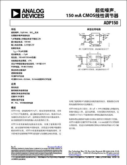
移动电话 数码相机和音频设备 便携式和电池供电设备 后置DC-DC调节 便携式医疗设备 RF、PLL、VCO和时钟电源
概述
ADP150是一款超低噪声(9 μV)、低压差线性调节器,采用 2.2 V至5.5 V电源供电,最大输出电流为150 mA。驱动150 mA 负载时压差仅为105 mV,这种低压差特性不仅可提高效率, 而且能使器件在很宽的输入电压范围内工作。
特性
超低噪声:9 μV rms,与VOUT无关 无需额外噪声旁路电容 1 μF陶瓷输入和输出电容下稳定工作 最大输出电流:150 mA 输入电压范围:2.2 V至5.5 V 低静态电流
IGND = 10 μA(空载) 低关断电流:< 1 μA 低压差:105 mV(150 mA负载) 初始输出电压精度:±1% 多达14种固定输出电压选项:1.8 V至3.3 V PSRR性能:70 dB (10 kHz) 限流和热过载保护 逻辑控制使能 5引脚TSOT封装 4引脚0.8 mm × 0.8 mm、0.4 mm间距WLCSP封装
VOUT = 1.8V
A
COUT
1µF
EN
GND B
图2. 4引脚WLCSP封装,固定输出电压1.8 V
08343-002
实现了超低噪声与低静态功耗的最佳组合,使便式应用 的电池使用时间可达到最长。
ADP150经过专门设计,在1 μF ± 30%小陶瓷输入和输出电 容便可稳定工作,适合高性能、空间受限应用的要求。它 可提供1.8 V至3.3 V范围内的14种固定输出电压选项。
ON
OFF
1 VIN VOUT 5 2 GND
VOUT = 1.8V
COUT 1µF
3 EN
NC 4
JW075A资料
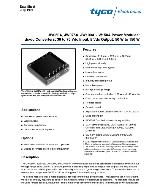
Small size: 61.0 mm x 57.9 mm x 12.7 mm (2.40 in. x 2.28 in. x 0.50 in.) High power density High efficiency: 84% typical Low output noise Constant frequency Industry-standard pinout Metal baseplate 2:1 input voltage range Overtemperature protection (100 W and 150 W only) Overcurrent and overvoltage protection Remote sense Remote on/off Adjustable output voltage: 60% to 110% of VO, nom Case ground pin ISO9001 Certified manufacturing facilities
s s s s s s s s s s s
The JW050A, JW075A, JW100A, and JW150A Power Modules use advanced, surface-mount technology and deliver highquality, efficient, and compact dc-dc conversion.
II, max II, max II, max II, max i2t II
— — — — — —
— — — — — 5
1.7 2.6 3.5 5.2 1.0 —
A A A A A2s mAp-p
—
—
60
—
dB
最全的 电子产品拆分电子元件中英文对照表

COVER CUSHION DATE LABEL D S TAPE D P PLATE DC CONVERTER DIGITAL PRINTER DIGITAL TRANSISTOR DIGITAL LABEL DIODE DISPLAY HOLDER DISPLAY SPACER DISPLAY FILTER DISPLAY FILTER
電子廠常用部品中英文對照表
NO. 英文名
001 AD SEAL 002 AD TAPE 003 ADDENDUM CARD 004 ADHESIVE GLUE 005 AL SHEET 006 ALUMINUM WIRE 007 ANTI STATIC BAG 008 B CARD 009 B COVER 010 B PLATE 011 BAR SOLDER 012 BAR-CODE NO. 013 BAR-CODE LABEL 014 BAT I LABEL 015 BATTERY COVER 016 BATTERY PLATE 017 BATTERY COVER 018 BATTERY ELECTRICAL WIRE 019 BATTERY INSULATING SEAL 020 BATTERY PLATE 021 BATTERY SPACER 022 BATTERY SPRING 023 B CARD 024 BC CARD 025 BIND TAPPING SCREW 026 BIND TP SCREW
EEE-HBA151UAP中文资料(panasonic)中文数据手册「EasyDatasheet - 矽搜」

500
(7)
500
(7)
500
(5)
2000
(5)
2000
(5)
1000
(5)
1000
(5)
1000
(5)
1000
(5)
900
(5)
1000
(7)
500
(7)
500
(7)
500
(7)
500
(7)
500
(7)
500
(5)
2000
(5)
2000
(5)
2000
(5)
1000
(5)
1000
(5)
1000
(5)
波纹
tan d
当前
(120赫兹)(120赫兹)
型号
(RoHS:合规)
(+105°C) (+20 °C)
(毫安均方根)
26
0.30 EEEHB0J220AR
29
0.30 EEEHB0J330AR
26
0.50 EEEHBJ470UAR
46
0.30 EEEHB0J470AR
42
0.50 EEEHBJ101UAR
100
0.16 EEEHBE101UAP
130
0.16 EEEHB1E101AP
130
0.30 EEEHBE221UAP
190
0.16 EEEHB1E221AP
130
0.30 EEEHBE331UAP
220
0.16 EEEHB1E331AP
230
0.30 EEEHBE471UAP
耐力:105℃,2000 ^ h
PA150使用说明书2007-11
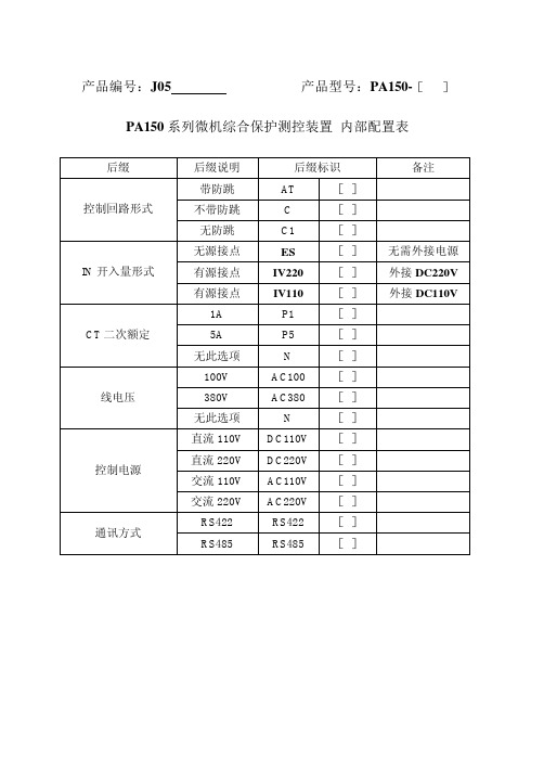
产品编号:J05 产品型号:PA150-[]PA150系列微机综合保护测控装置内部配置表后缀后缀说明后缀标识备注带防跳AT []控制回路形式不带防跳 C []无防跳C1 []无源接点ES []无需外接电源IN开入量形式有源接点IV220 []外接DC220V有源接点IV110 []外接DC110V1A P1 []CT二次额定5A P5 []无此选项N []100V AC100 []线电压380V AC380 []无此选项N []直流110V DC110V []直流220V DC220V []控制电源交流110V AC110V []交流220V AC220V []RS422 RS422 []通讯方式RS485 RS485 []亲爱的用户:注意事项:l 装置外壳可靠接地。
l 装置严禁带电拔插通讯接头。
l 装置的开入量为有源还是无源接点输入。
l 现场调试时应注意大电流通电时间不能过长,本装置交流回路2倍额定电流时刻连续工作,10倍额定电流时允许10s, 40倍额定电流时允许1s。
l 装置工作电源为交直流两用电源。
l 电流输入极性是否正确,电压输入相序是否正确。
目录一、主要用途及适用范围二、使用条件要求三、前面板布置及操作简介四、后面板布置及简介五、通讯接口定义及连接方式六、安装调试七、菜单介绍八、其他一、 概述1.1主要用途及适用范围PA150系列微机保护测控装置是南京因泰莱电器股份有限公司(INT)在吸收国内外先进技术基础上,根据中国电力系统的需求而研制和生产的产品。
该系列装置具有强大的功能集成,外观时尚、结构精巧、大屏幕液晶显示,图形化中文菜单,四位方向导航盘,操作快捷方便。
该系列装置集保护、测量、控制、监测、通讯、故障录波、事件记录等多种功能于一体。
高精度测量电流、电压、功率、功率因数、频率、零序电流、零序电压、计算电度;在线记录事件量达64条,先进先出(FIFO)动态刷新,带有时间标记,掉电不丢失。
GKP150说明书

目录1简介 (2)1.1应用范围 (2)1.2主要特点 (2)2安装 (3)2.1开孔和固定 (3)2.2接线 (4)2.3现场服务注意事项 (5)3操作说明 (6)3.1面板功能 (6)3.2页面浏览简明结构图 (7)3.3页面说明 (8)4保护原理 (14)4.1CT断线告警 (14)4.2电流速断保护 (14)4.3定时限过流保护 (14)4.4反时限过流保护 (15)4.5过负荷保护 (16)4.6零序电流保护 (16)4.7非电量保护 (16)5调试大纲 (17)5.1通电前检查 (17)5.2通电检查 (17)5.3投运前检查 (18)5.4投运后注意事项 (18)5.5运行维护注意事项 (18)附录A技术参数表 (19)附录B系统参数整定表 (21)附录C典型电气接线图 (22)声明:我公司保留对所有产品技术参数更新的权利,最新资料请登录公司网站查询(),若有变动恕不另行通知。
1简介1.1应用范围GKP150系列数字式多功能继电器是我公司推出的以电流电压保护为基本配置的数字式保护单元,适用于我国10kV及以下电压等级的工矿企业,民用建筑配电的小电流接地系统,作为各类电气设备和线路的主保护或后备保护。
GKP150采用微处理器,运用数字处理技术,实现各种保护,以替代传统电磁继电器,实现保护的数字化,智能化。
GKP150的主要功能:1)电流测量:IA、IB、IC、I02)开关量监测:IN1~IN8,8路开关量监测3)电流保护功能:1.电流速断保护2.定时限过电流保护3.反时限过电流保护4.过负荷保护5.零序电流保护4)非电量保护:1.高温告警2.超温跳闸3.轻瓦斯告警4.重瓦斯跳闸5)CT断线告警6)信号继电器输出1.故障跳闸信号2.预告报警信号3.装置故障信号:装置工作正常时线圈通电,节点85闭合,节点86打开。
1.2主要特点◆GKP150系列数字式多功能继电器不仅拥有继电保护完整的保护功能,而且对所有测量量进行数字化的处理和计算,保证了继电保护的可靠性和安全性。
Z15GQB7K中文资料(omron)中文数据手册「EasyDatasheet - 矽搜」

H (0.25 mm) Model Z-15H Z-15H-B Z-15HS Z-15HS-B Z-15HD Z-15HD-B --Z-15HQ Z-15HQ-B --Z-15HQ22 Z-15HQ22-B Z-15HQ21 Z-15HQ21-B ------Z-15HW Z-15HW-B
H2 (0.20 mm) Model Z-15H2 Z-15H2-B -----
H (0.25 mm) Model -----------
H2 (0.20 mm) Model -----------
E (1.8 mm) Model -----------
H (0.25 mm) Model -----------
lever
单向 短铰链滚轮 并行
lever
反向铰链杆
Z-15GW2277-B Z-15GM Z-15GM-B Z-15GM22 Z-15GM22-B Z-15GM2 Z-15GM2-B
Model --Z-15GA55-B5V ------Z-15GK3A55-B5V --Z-15GQA55-B5V --Z-15GQ22A55-B5V --Z-15GQ21A55-B5V --------Z-15GW44A55-B5V --Z-15GWA55-B5V --Z-15GW22A55-B5V --Z-15GW2A55-B5V --Z-15GW2277A55B5V -------
E (1.8 mm) Model Z-15E Z-15E-B --Z-15ED Z-15ED-B ---
H (0.25 mm) Model Z-01H Z-01H-B Z-01HS Z-01HS-B Z-01HD Z-01HD-B --Z-01HQ Z-01HQ-B -------------
鼎阳科技射频产品手册说明书
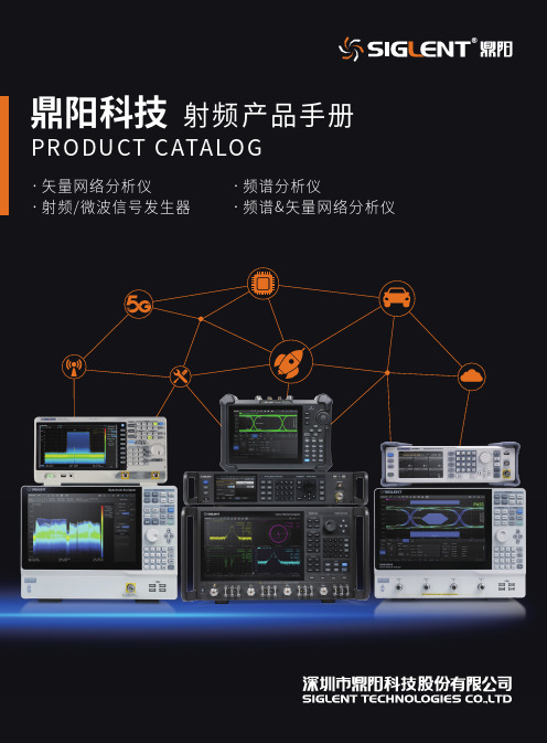
1目 录CONTENTS02 06 08 12 15 19 24 28 32 34 38 41 43 4649 56公司简介.......................................................................................................................................................................................................... 频谱分析仪SSA5000A 系列频谱分析仪................................................................................................................................................................... SSA3000X-R 系列实时频谱分析仪.................................................................................................................................................... SSA3000X PLUS 系列频谱分析仪..................................................................................................................................................... SHA850A 系列手持频谱分析仪.......................................................................................................................................................... 频谱&矢量网络分析仪SVA1000X 系列频谱&矢量网络分析仪........................................................................................................................................ 矢量网络分析仪SNA6000A 系列矢量网络分析仪....................................................................................................................................................... SNA5000A 系列矢量网络分析仪....................................................................................................................................................... SNA5000X 系列矢量网络分析仪....................................................................................................................................................... SHN900A 系列手持矢量网络分析仪.............................................................................................................................................. 射频/微波信号发生器SSG6000A 系列微波信号发生器....................................................................................................................................................... SSG5000A 系列微波信号发生器....................................................................................................................................................... SSG5000X 系列射频模拟/矢量信号发生器............................................................................................................................. SSG3000X 系列射频信号发生器....................................................................................................................................................... 探头及附件 其他探头及配件........................................................................................................................................................................................... 售后承诺........................................................................................................................................................................................................... 2通用电子测试测量仪器领域的行业领军企业公司战略Every Bench. Every Engineer. Every Day.深圳市鼎阳科技股份有限公司(简称“鼎阳科技”,股票代码:688112)是通用电子测试测量仪器领域的行业领军企业,A 股上市公司。
FA-150中文操作说明书

FA-150中文操作说明书拓洋无线电设备市番禺区市桥镇富华东路82号番安综合市场32-34号:8 传真:81.1 按键控制的描述盘①显示屏幕②光标键③菜单键④确认键⑥调节亮度⑤显示键⑦导航状况键⑧开关键1.2 开机/关机①按[POWER]键开机/关机按[POWER]键开机/关机。
当开机时, 设备会哔哔几秒钟,然后显示如下:设备确认屏幕开始屏幕图表显示1.3 调节面板的对比度和亮度面板的对比度和亮度调节如下:①按DIM]键就会出现以下对话框②使用▼或▲键调节面板亮度; ▼或▲键调节对比度③按[ENT]键,关闭对话框1.4 菜单概述你可以从设备中选择功能菜单,如果你不会操作,按[MENU]键,直到你进入主菜单为止,所有的菜单都在菜单列表中1、按下[MENU]键打开主菜单2、使用[CURSORPAD]键选择你想要菜单,然后按[ENT]键3、使用[CURSORPAD]键选择附属菜单,再按[ENT]键,这里有两种类型可供选择,选项和数据登记。
下面的例子就是其中一种选择的类型4、使用▼或▲键,选择你想要的加工项目,按[ENT]键确认5、利用附属菜单选择选项或文字数字的数据选择选项下面的例子就是如何从使用者设置菜单中选择选项A、使用▼或▲键选择想要的项目菜单,按[ENT]键确认就会出现以下窗口选择窗口B、按▼或▲键选择你想要的选择按[ENT]键确认输入文字数字的数据A)选择[DRAUGHT]项,按[ENT]键确认游标B)使用▼或▲键选择适当的数字C)使用键将光标移移到附近的地方,同时按▼或▲键选择数字D)重复C)这一步完成数据输入E)按[ENT]键记录数据6、按[DISP]键关闭菜单1.5 设置航程1、按下[NAV STATUS]键打开航行状态菜单2、如果你照旧航行就会展示以下步骤,如果展示相同就可以直接跳到第3步A、按下[ENT]键B、按▼或▲键选择适当的情况并按[ENT]键,涉及的数据可以根据下面选择适当的导航情况3、按键就会显示NAV状态菜单的第2页NAV状态菜单第2页4、 [NEW]项已选择;[按[ENT]键5、按下[ENT]键,使用[CURSORPAD]键输入目的地并按[ENT]键,你可以输入20个字母、数字、符号,和你可以输入20个目的地目的地处理如果您已经登记一些目的地, NAV状态菜单第2页下面如下。
贴片电容容量范围
4.7
ACCCG GGG J J J J J J J J J J J
5.6
ACCCG GGG J J J J J J J J J J J
6.8
ACCCG GGG J J J J J J J J J J J
8.2
ACCCG GGG J J J J J J J J J J J
10
ACCCG GGG J J J J J J J J J J J
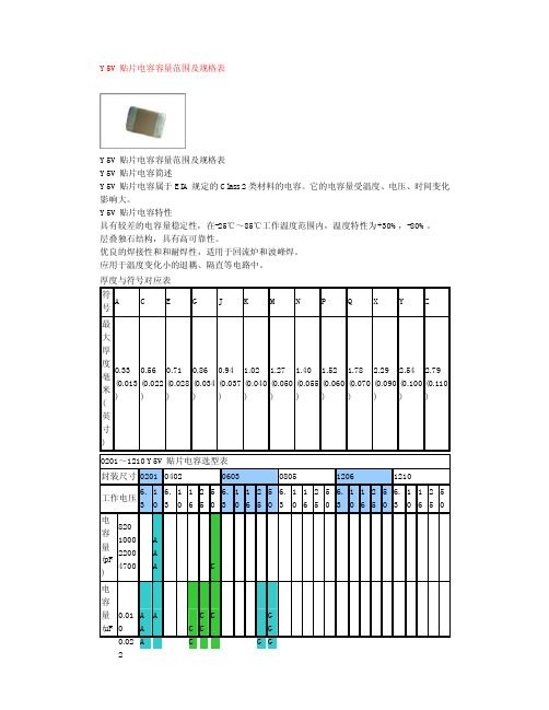
Y5V 贴片电容容量范围及规格表
Y5V 贴片电容容量范围及规格表 Y5V 贴片电容简述 Y5V 贴片电容属于 EIA 规定的 Class 2 类材料的电容。它的电容量受温度、电压、时间变化 影响大。 Y5V 贴片电容特性 具有较差的电容量稳定性,在-25℃~85℃工作温度范围内,温度特性为+30%,-80%。 层叠独石结构,具有高可靠性。 优良的焊接性和和耐焊性,适用于回流炉和波峰焊。 应用于温度变化小的退耦、隔直等电路中。
K K K P Q MM M K K K P Q MM M K K K P Q MM M
MM P MM P MM P
5600 J J M 6800 J J 8200 J J
K K M P X MM M
MM P
KKM X
MM M P MM P
K MM X
MM
P MM P
0.010 N N 0.012 N N 0.015
厚度与符号对应表
符
号A
C
E
G
J
K MN P
QXYZ
最 大
厚
度 0.33 0.56 0.71 0.86 0.94 1.02 1.27 1.40 1.52 1.78 2.29 2.54 2.79
- 1、下载文档前请自行甄别文档内容的完整性,平台不提供额外的编辑、内容补充、找答案等附加服务。
- 2、"仅部分预览"的文档,不可在线预览部分如存在完整性等问题,可反馈申请退款(可完整预览的文档不适用该条件!)。
- 3、如文档侵犯您的权益,请联系客服反馈,我们会尽快为您处理(人工客服工作时间:9:00-18:30)。
© Faraday Technology. As part of continual product improvement the specifications, details and dimensions shown in this publication are subject to change without notice
• Suitable for 1.5 Gb/s or 540 Mb/s operation • Robust construction
• Simulates up to 150 metres of Belden 8281• Cross reference to other cables • Known, accurate loss vs frequency characteristic • >15 dB return loss to 750 MHz • Resolution down to 10 metres of Belden 8281• Shielded metal case size
• Convenient, patchable cable lengths • 75 ohm Female BNC’s
In bit-serial digital coaxial interfaces for HDTV component signal data rates of 1.5 Gb/s are common. It is known that a signal adhering to SMPTE 292M will ensure correct operation of automatic cable equalisers provided a coaxial cable with a 1/f frequency response from 1 MHz to the clock frequency is used.
The Faraday HDTV cable clone has a known, accurate loss vs frequency characteristic against cable over the significant frequency spectrum of the serial digital signal. It can therefore be used as a more convenient substitute for actual cable when installing or testing HDTV serial digital equipment to ensure sufficient margin (head room) is available, or to establish the maximum length of cable over which the serial digital signal will remain usable. The individual cable lengths may be patched together to simulate a maximum length of 150 metres. The use of switches has been avoided as they introduce unacceptable errors into the simulation.
Order code
FPC150A075Impedance
75 ohms Cable type
Belden 8281 (cross reference for BBC PSF 1/2M, 1/3M and RG59)Cable lengths simulated
10m + 20m + 40m + 80m Amplitude variation wrt 8281
300 kHz to 750 MHz 300 kHz to 1.5 GHz 10m section
< 1 dB < 2 dB 20m section
< 1 dB < 2 dB 40m section
< 1 dB < 4 dB 80m section
< 1 dB < 4 dB Total
< 4 dB < 10 dB
Return loss to 750 MHz > 15 dB Other cable types and lengths may be simulated, please contact Faraday for availability.
FPC150A075
HDTV CABLE CLONE
PACKAGE DETAIL
Faraday Technology Ltd.Tel:+ 44 (0)1782 661501 Croft Road Industrial Estate,Fax:+ 44 (0)1782 630101 Newcastle, Staffordshire Email:sales@ ST5 0QZ. England.Web site:。
