STK672-040驱动芯片产品使用手册
Agilent EPM 和 EPM-P 系列电源计及 E-系列功率传感器配置指南说明书

Agilent EPM and EPM-P SeriesPower MetersE-Series Power SensorsConfi guration GuideIntroductionThis configuration guide describesstandard configurations, optionsand compatible accessories. For fullspecifications, see EPM Series PowerMeters and E-Series Power SensorsTechnical Specifications (Agilentliterature number 5965-6382E), orEPM-P Series Power Meters andE9320 Power Sensors TechnicalSpecifications (Agilent literaturenumber 5980-1469E). Contact yourlocal Agilent Technologiesrepresentative at the offices listedon the back of this guide if you needmore information.EPM Series Power Meters•E4418B Power Meter (single channel)•E4419B Power Meter (dual channel)EPM-P Series Power Meters•E4416A Power Meter (single channel)•E4417A Power Meter (dual channel)E-Series Power Sensors•E441XA CW Power Sensors(10 MHz to 26.5 GHz, sensor dependent)•E9300 Average Power Sensors(9 kHz to 18 GHz, sensor dependent)•E9320 Peak and Average Power Sensors(50 MHz to 18 GHz, sensor dependent)EPM-P Series Power MetersThe EPM-P Series power meters provide peak, peak-to-average ratio, average, and time-gated power measurements. For peak, peak-to-average ratio, and time-gated measurements, the EPM-P Series power meters must operate with the E-Series E9320 power sensors. For average power measurements only, the EPM-P Series power meters are compatible with all the 8480 Series power sensors, the E-Series CW, the E-Series E9300 average power sensors, and the E-Series E9320 power sensors.The standard EPM-P Series power meters include:Single-channel power meter, order• E4416Aor dual-channel power meter, order E4417A•Input sensor connector(s) on the front panelReference calibrator connector on the front panel•• Installations GuidePrinted copy of English-language• User’s Guide (Option ABA)Printed copy of English-language• User’s Guide, English-CD-ROM, contains the English-language and localizedlanguage Programming Guide and Agilent EPM-P analyzer software•Supplied accessories:• E9288A), one per E4416A and two per Power sensor cable (1.5 meter (5 ft)E4417A•Power cord (plug matches destination requirements)EPM Series Power MetersThe EPM Series power meters provide average power measurements.The standard E4418B and E4419B power meters include:• E4418B, Single-channel power meter, orderor dual-channel power meter, order E4419B•Input sensor connector(s) on the front panel•Reference calibrator connector on the front panelPrinted copy of English-language• User’s Guide (Option ABA)•Supplied accessories:Power sensor cable (1.5 meter (5 ft)• 11730A), one per E4418B and two per E4419B•Power cord (plug matches destination requirements)E-Series Power SensorsThe standard E4412A and E4413A CW power sensors include:• E4412A, Power sensor 10 MHz to 18 GHz, orderor power sensor 50 MHz to 26.5 GHz, order E4413A • Operating and Service GuideEnglish-languageThe standard E9300 average power sensors include:+20 to –60 dBm:• E9300APower sensor 10 MHz to 18 GHz, order• E9301APower sensor 10 MHz to 6 GHz, order• E9304APower sensor 9 kHz to 6 GHz, order• E9304A Option H18Power sensor 9 kHz to 18 GHz, order• E9304A Option H20 Power sensor 9 kHz to 18 GHz, order(APC 3.5 mm connector)+30 to –50 dBm:Power sensor 10 MHz to 18 GHz, order• E9300HPower sensor 9 kHz to 18 GHz, order• E9300H Option H19Power sensor 10 MHz to 6 GHz, order• E9301H+44 to –30 dBm:Power sensor 10 MHz to 18 GHz, order• E9300BPower sensor 10 MHz to 6 GHz, order• E9301BEnglish-language• Operating and Service Guide(part number E9300-90009)The standard E9320 peak and average power sensors include:Power sensor, 50 MHz to 6 GHz, 300 kHz bandwidth, order• E9321APower sensor, 50 MHz to 6 GHz, 1.5 MHz bandwidth, order• E9322APower sensor, 50 MHz to 6 GHz, 5 MHz bandwidth, order• E9323APower sensor, 50 MHz to 18 GHz, 300 kHz bandwidth, order• E9325APower sensor, 50 MHz to 18 GHz, 1.5 MHz bandwidth, order• E9326APower sensor, 50 MHz to 18 GHz, 5 MHz bandwidth, order• E9327AEnglish-language• Operating and Service GuideCompatibilityPower sensor compatibilityFor compatibility of power meters, power sensors, and power sensor cables, please refer to the table below.Power Sensors Power Meters Power Sensor CablesEPM-P Series EPM Series 11730 (grey)E9288 (blue) E441X family Yes Yes Yes YesE9300 family Yes Yes1Yes YesE9320 family Yes No No Yes8480 Series Yes Yes Yes YesFirmware compatibilityThe table below shows the required revision of firmware for operation of theE9300 power sensors as well as the part number of the required hardware upgrade kit.E4418A/E4419AFirmware Hardware E4418B/E4419B FirmwareE9300A/01A/04A Rev A1.04.00/A2.04.00E4418-60021Rev A1.04.00/A2.04.00 E9300H/01H Rev A1.06.00/A2.06.00E4418-60021Rev A1.06.00/A2.06.00 E9300B/01B Rev A1.06.00/A2.06.00E4418-60021Rev A1.06.00/A2.06.00Please refer to the fi rmware compatibility table to ensure compatibility for this combination.1.Firmware upgrade information can be accessed from the World Wide Web, free of charge. It can also be purchased as a firmware upgrade kit, Agilent part num-ber E4418-61035. The hardware upgrade is a simple upgrade and the kit provides the parts required. The upgrade can be performed at any local Service Center or at a customer site.Hardware OptionsThe following options are available on the EPM and EPM-P Series power meters.Option Description EPM-P SeriesPower Meter EPM Series Power MeterE441xA/B-001Internal rechargeable battery No YesE441xA/B-002Parallel rear panel sensor inputconnector(s) and front panelreference calibrator connectorYes YesE441xA/B-003Parallel rear panel sensor inputconnector(s) and rear panelreference calibrator connectorYes YesE441xA/B-004Delete power sensor cable Yes YesE441xA/B-908Rack mount kit (one instrument)Yes YesE441xA/B-909Rack mount kit (two instruments)Yes Yes Service and Support OptionsWarrantyA standard 12 months, return to Agilent warranty and service plan is included with each EPM and EPM-P Series power meter.Calibration1Order 36 months of the appropriate calibration plan as shown below.R-50C-001 Standard calibration planR-50C-002 Standard compliant calibration planSpecial OptionsSpecial options for EPM-P Series power meters, EPM Series power meters, and E-Series sensors are available. Contact your local Agilent representative for more information.Options are not available in all countries.1.DocumentationThe EPM power meters are supplied with a printed copy of English-language •User’s Guide (Option ABA).The EPM-P power meters are supplied with a printed copy of• Installation Guide which includes all languages, a printed copy of English-language User’s Guide (Option ABA), and a CD-ROM which contains Agilent EPM-P analyzer software, User’s Guide and Programming Guide, and the localized versions of User’s Guide.Documentation EPM-P SeriesPower Meter EPM Series Power MeterEnglish-languageProgramming GuideE441xA-0BF E441xB-0BFService Guide E441xA-0B3E441xB-915Delete manual set E441xA-0B0E441xB-0B0Add manual set (English),User’s Guide andProgramming GuideE441xA-0BK E441xB-916Documentation E4412/3A E9300E9320AAdd manual set E4412/3A-0B1E930xx-0B1E932xA-0B1 Localization OptionsThe following table shows the option number to order the documentation.The following options provide a printed copy of localized User’s Guide. For the EPM-P, the localized manuals are all available on the CD-ROM supplied with the product. The localized options for the EPM-P provide a printed copy of localized User’s Guide and a printed copy of English-language Programming Guide.Language EPM-P SeriesPower Meter EPM SeriesPower MeterE4412/3ASensorsE9300SensorsGerman E441xA-ABD E441xA-ABD E4412/3A-ABD E930xx-ABD Spanish E441xA-ABE E441xA-ABE E4412/3A-ABE E930xx-ABE French E441xA-ABF E441xA-ABF E4412/3A-ABF E930xx-ABF Japanese E441xA-ABJ E441xA-ABJ E4412/3A-ABJ E930xx-ABJ Italian E441xA-ABZ E441xA-ABZ E4412/3A-ABZ E930xx-ABZ Korean Not available Not available Not available E930xx-ABICalibration OptionsOption E441xA/B-A6J - Supplies ANSI Z540 certificate of calibration with data. Option E93xxA/B/H-A6J - Supplies ANSI Z540 certificate of calibration with data.Available Accessories•E9288A-C power sensor cables (refer to the compatibility section):• E9288A1.5 meters (5 ft)• E9288B3 meters (10 ft)• E9288C10 meters (31 ft)•11730A-F power sensor cables (refer to the compatibility section):1.5 meters (5 ft)• 11730A• 11730B3 meters (10 ft)• 11730C6.1 meters (20 ft)15.2 meters (50 ft)• 11730D• 11730E30.5 meters (100 ft)• 61 meters (200 ft) 11730F• 34161AAccessory pouch,Holds accessories supplied or orderedBasic instrument transit case,• 34131AProtects the power meter during transit• 34141ASoft carry/operating case,Power meter with battery option can be operated in soft carry case• E9287ASpare battery,Extra battery for EPM Series power meters with Option 001 Auxiliary EquipmentThe 11683A range calibrator verifi es the accuracy and linearity of the EPM-P and EPM Series power meters. Outputs corresponding to the meter readings of 3, 10, 30, 100, and 300 μW and 1, 3, 10, 30 and 100 mW are provided. Calibration uncertainty is ±0.25% on all ranges.Literature References• , EPM-P Series Power Meters and E9320 Sensors, Product Overview literature number 5980-1471EEPM-P Series Power Meters and E9320 Sensors, Technical Specifications • , literature number 5980-1469E• , EPM-P Series Single and Dual Channel Power Meters, Demo Guide literature number 5988-1605EN• , EPM-P Series Power Meters, CD-ROMpart number E4416-90032• , Choosing the Right Power Meter and Sensor, Product Noteliterature number 5968-7150E•EPM Series Power Meter and E-Series Power Sensors, Technical Specifications, literature number 5965-6382EEPM Series Power Meter and E-Series Power Sensors, Brochure• , literature number 5965-6380E• , Fundamentals of RF and Microwave Power Measurements, Application Note 64-1 literature number 5965-6630E• , 4 Steps for better Power Measurements, Application Note 64-4literature number 5965-8167E•E-Series E9300 Power Sensors, Product Overview,literature number 5968-4960ERemove all doubt Our repair and calibration services willget your equipment back to you, per-forming like new, when promised. You will get full value out of your Agilent equipment through-out its lifetime. Your equipment will be serviced by Agilent-trained technicians using the latest factory calibration procedures, automated repair diagnostics and genuine parts. You will always have the utmost confidence in your measure-ments. For information regarding self maintenance of this product, please contact your Agilent office.Agilent offers a wide range of addi-tional expert test and measurement services for your equipment, including initial start-up assistance, onsite edu-cation and training, as well as design, system integration, and project man-agement.For more information on repair and calibration services, go to:/find/removealldoubt Agilent Email Updates /find/emailupdates Get the latest information on the products and applications you select.Agilent Direct LXI is the LAN-based successor to GPIB, providing faster, more efficient connectivity. Agilent is a founding member of the LXI consortium.Agilent Channel Partners w w w /find/channelpartners Get the best of both worlds: Agilent’s measurement expertise and product breadth, combined with channel partner convenience.For more information on AgilentTechnologies’ products, applications or services, please contact your local Agilent office. The complete list is available at:/find/contactus Americas Canada (877) 894 4414 Latin America 305 269 7500United States (800) 829 4444Asia Pacifi c Australia 1 800 629 485China 800 810 0189Hong Kong 800 938 693India 1 800 112 929Japan 0120 (421) 345Korea 080 769 0800Malaysia 1 800 888 848Singapore 180****8100Taiwan 0800 047 866Thailand 1 800 226 008 Europe & Middle East Belgium 32 (0) 2 404 93 40 Denmark 45 70 13 15 15Finland 358 (0) 10 855 2100France 0825 010 700* *0.125 €/minuteGermany 49 (0) 7031 464 6333 Ireland 1890 924 204Israel 972-3-9288-504/544Italy 39 02 92 60 8484Netherlands 31 (0) 20 547 2111Spain 34 (91) 631 3300Sweden 0200-88 22 55Switzerland 0800 80 53 53United Kingdom 44 (0) 118 9276201Other European Countries:/fi nd/contactus Revised: October 1, 2009Product specifications and descriptions in this document subject to change without notice.© Agilent Technologies, Inc. 2009Printed in USA, October 27, 20095965-6381E /find/powermeters。
STK672-080电机驱动使用说明

STK672—0801图中:(1)LM317稳压块,是专门给555和STK672-080电路供电.电压为5伏。
(2,3,4)是可通过三个输入(M1,M2和M3)选择五种激励(通电)方式,包括:2相通电方式、1-2通电方式、W1-2相退方式、2W1-2相通电方式、4W1-2相通电方式等;(5)ENABLE:ON/OFF状态控制输出端。
当ENABLE端的电压为高或开路时,为正常状态。
当ENABLE为低时,电路处于维持状态,此时相激励输出(电动机电流)强制关闭。
在这个模态中,系统时钟和其它输入均无效。
(6)CWB:转向设定端。
当CWB为高时,电动机旋转方向为顺时针;当CWB为低时,电动机旋转方向为逆时针。
(7)MOI:原点监视引脚;(8)CLK:时钟输入。
输入频率范围可从直流到50kHz,最小脉冲宽度为10μs,占空比范围为40~60%。
此外,该端内部具有上拉电阻(典型值为20kΩ)、CMOS施密特触发器电路和多级噪声抑制电路。
当M3为高或开路时,电路会在每个CLK上升沿使相激励前进一步;而当M3为低时,CLK信号的上升和下降沿都可使相激励前进步,因此每一个CLK周期可使相激励前进两步。
(9)Vref:PWM恒流环控制参考电压,用于根据需要控制负载电流的大小,通常Vref应限制在2.5V以下。
此参考电压对应于100%的电机激励电流Ioh,其关系如下:Ioh=Vref/(kRS)式中,k可取4.7,Rs的值为0.15Ω时,Ioh为Vref/0.705。
(10)555调频电位器,给驱动器供工作频率的(11)GND(12) VCC(13) VCC(14 ,15 ,16 ,17) 输出四路信号接电机(18)555脉冲产生芯片2单片机控制:通过单片机给驱动器CLK端加入一个信号,通过单片机改变频率来控制电机,(注:必须得共地)。
STK672-080应用
•””•5国外电子元器件6’••“年第™期’••“年™月p新特器件应用四相步进电机正弦波驱动器³´«–—’••˜•及其应用谭建成ˆ广州电器科学研究院Œ广东广州•‘•“•’‰A St e pp in g M otor Sine Wav e Dr i v e r ST K672-080and I t s A pp l i ca t i on´¡®ªÉÁΕÃÈÅÎÇ摘要š³´«–—’••˜•是³¡®¹¯公司生产的一种”相步进电动机驱动器厚膜混合集成电路Œ它的输出电流很大Œ且有五种激励方式Œ利用³´«–—’••˜•内部的微步距正弦波控制器可使电动机运行在低振动和低噪音的工作状态"关键词š步进电动机›厚膜混合集成电路›³´«–—’••˜•›微步距分类号š´-“˜“Ž–文献标识码š¢文章编号š‘••–•–™——ˆ’••“‰•™•••””••“••向µ³¢主机写数据ÁÌ×ÁÙÓ ˆÐÏÓÅÄÇÅÃÌËÏÒÎÅÇÅÄÇÅÒÅÓÅÔ‰ÂÅÇÉÎÉƈÒÅÓÅÔ••‘c•‰ÔØÄÁÔÁœ•˜cÈ••›ÅÌÓÅÉƈÃÎÔ»•½••‘c‘‰ÔØÄÁÔÁœ•ÄÁÔÁ”’™›ÅÎÄ•••••••••••••••••••••••••¦´’”•¡-与¥°-—‘’˜³的数据三态接口ÁÓÓÉÇÎÕÓÂÄÁÔÁ•ˆÃÎÔ»‘½••‘c‘‰ŸÔØÄÁÔÁš˜cÈÚÚ›•••••••••••••••••••••••“结束语本文介绍了µ³¢接口芯片¦´’”•¡-的原理和在航空¡²©®£”’™总线测试仪中的具体应用实例方法"笔者将¥°-—‘’˜与¦´’”•¡-的接口逻辑在-¡¸ÐÌÕÓÒ环境下进行了仿真Œ结果表明š使用该设计完全可满足实际要求Œ因此Œ使用µ³¢通信接口的航空¡²©®£”’™总线测试仪Œ大大便利了”’™总线设备与计算机的通信Œ有效提高了”’™总线设备的检测效率"参考文献»‘½徐志军Œ徐光辉Ž£°¬¤•¦°§¡的开发与应用»-½Ž北京š电子工业出版社Œ’••’Ž»’½µÎÉÖÅÒÓÁ̳ÅÒÉÁÌ¢ÕÓ³ÐÅÃÉÆÉÃÁÔÉÏÎŽ£ÏÍÐÁÑ©ÎÔÅÌ-ÉÃÒÏÓÏÆÔ®¥£Œ‘™™˜Ž»“½¦´’”•¡-¤ÁÔÁ³ÈÅÅÔŽ¦¤´©Œ‘™™™Ž»”½-¡¸—•••°ÒÏÇÒÁÍÍÁÂÌŬÏÇÉäÅÖÉÃŦÁÍÉÌÙ¤ÁÔÁ³ÈÅÅÔŽ¡ÌÔÅÒÁŒ’••‘Ž收稿日期š’••“••”•‘•咨询编号š•“•™‘•‘³´«–—’••˜•的主要特点³´«–—’••˜•是³¡®¹¯公司生产的一种步进电动机驱动器厚膜混合集成电路Œ它的输出级使用功率-¯³¦¥´组成Œ同时包含一个内部的微步距控制器和一个单极性的恒流°·-系统"³´«–—’••˜•内部提供的”相步进电动机分配控制器可获得准正弦波驱动电流Œ从而使用户应用更简单方便"它有五种激励ˆ通电‰方式Œ可提供微步距控制以使步进电动机的基本步距角的最大细分为‘•‘–"³´«–—’••˜•步进电机控制器的速度由时钟信号控制"通过它可使用户方便地实现高转!低振动水平!低噪音!快速响应和高效驱动的电动机控制系统"³´«–—’••˜•的典型应用包括传真机发送与接收步进电动机驱动!复印机送纸和光学系统步进电动机驱动!激光打印机鼓驱动!打印机台架步进电动机驱动!¸•¹绘图仪笔驱动!工业机械手以及其它步进电动的应用方面Œ其主要特点如下šp只需外加一个直流电源和一个时钟脉冲发生器即可完成一个四相步进电机正弦波电流驱动"p可通过三个输入ˆ-‘Œ-’和-“‰选择五种激励ˆ通电‰方式Œ包括š’相通电方式!‘•’通电方式!·‘•’相退方式!’·‘•’相通电方式!”·‘•’相通电方式等›•”••p在相通电方式切换时可保持原相电流不变›p可用-¯©脚作原点监视›p利用-“端的逻辑电平可选择时钟信号上升沿起作用或时钟信号上升沿和下降沿都起作用›p£¬«输入端内含对外部脉冲噪音的故障防止线路›p用参考电压¶ÒÅÆ能设置•*¶££’•’之间的任何数值Œ即使低电流下也支持微步距操作›p电源电压范围宽ˆ¶££‘•‘•*”•¶‰›p内部带有电流传感电阻ˆ•Ž‘•8‰›p内含最小驱动损耗的-¯³¦¥´Œ耐压为‘••¶›p电动机输出最大驱动电流I OH为’Ž˜¡ˆ结温T C•‘••e‰›p采用特殊的³©°‘•单列直插式形式"’结构原理与引脚功能³´«–—’••˜•内部由控制和功率部分组成"功率级有”个-¯³¦¥´Œ并按低侧驱动方式工作Œ其中¡相和¢相内部有电流传感内阻和比较器Œ可用来实现相电流的°·-控制"控制部分的关键是有电流分配比开关和准正弦波发生电路"³´«–—’••˜•可由三个输入逻辑来选择通电方式Œ并由外接参考电压V r ef来设定最大电流值Œ以便在相电流°·-控制下得到相应的输出电流波形"图‘所示是³´«–—’••˜•内部结构"现将其各主要引脚的功能说明如下š£¬«š时钟输入"输入频率范围可从直流到••Ë¨ÚŒ最小脉冲宽度为‘•LÓŒ占空比范围为”•*–•…"此外Œ该端内部具有上拉电阻ˆ典型值为’•Ë8‰!£-¯³施密特触发器电路和多级噪声抑制电路"当-“为高或开路时Œ电路会在每个£¬«上升沿使相激励前进一步›而当-“为低时Œ£¬«信号的上升和下降沿都可使相激励前进一步Œ因此每一个£¬«周期可使相激励前进两步"£·¢š转向设定端"当£·¢为高时Œ电动机旋转方向为顺时针›当£·¢为低时Œ电动机旋转方向为逆时针"¥®¡¢¬¥š¯®•¯¦¦状态控制输出端"当¥®¡¢¬¥端的电压为高或开路时Œ为正常状态"当¥®¡¢¬¥为低时Œ电路处于维持状态Œ此时相激励输出ˆ电动机电流‰强制关闭"在这个模态中Œ系统时钟和其它输入均无效"-‘Œ-’和-“š用于选择激励方式和£¬«输入边缘作用Œ内有上拉电阻ˆ典型值’•Ë8‰和£-¯³施密特触发器电路"表‘是-‘!-’和-“的操作真值表"图’为其操作时序"²¥³¥´š复位端Œ低电平有效"²¥³¥´脚为低电平时Œ所有电路复位到它们的起始状态"此时Œ不管通电方式如何Œ输出¡和¢相都置于它们的原点Œ即输出电流约在—‘…处"¶ÒÅÆš°·-恒流环控制参考电压Œ用于根据需要控制负载电流的大小Œ通常¶ÒÅÆ应限制在’Ž•¶以下"此参考电压对应于‘••…的电机激励电流I OHŒ其关系如下š四相步进电机正弦波驱动器³´«–—’••˜•及其应用•”–•5国外电子元器件6’••“年第™期’••“年™月。
AT6720 直流程控电源 用户手册说明书

Rev.A1固件说明:适用于主程序RevA1.0及以上的版本AT6720 直流程控电源@安柏®是常州安柏精密仪器有限公司的商标或注册商标。
常州安柏精密仪器有限公司Applent Instruments Ltd.江苏省常州市武进区漕溪路9号联东U谷14栋电话:*************传真:*************销售服务电子邮件:*****************技术支持电子邮件:****************©2005-2021 Applent Instruments.声明根据国际版权法,未经常州安柏精密仪器有限公司(Applent Instruments Inc.)事先允许和书面同意,不得以任何形式复制本文内容。
安全信息为避免可能的电击和人身安全,请遵循以下指南进行操作。
免责声明用户在开始使用仪器前请仔细阅读以下安全信息,对于用户由于未遵守下列条款而造成的人身安全和财产损失,安柏仪器将不承担任何责任。
仪器接地为防止电击危险,请连接好电源地线。
不可在爆炸性气体环境使用仪器不可在易燃易爆气体、蒸汽或多灰尘的环境下使用仪器。
在此类环境使用任何电子设备,都是对人身安全的冒险。
不可打开仪器外壳非专业维护人员不可打开仪器外壳,以试图维修仪器。
仪器在关机后一段时间内仍存在未释放干净的电荷,这可能对人身造成电击危险。
不要使用工作异常的仪器如果仪器工作不正常,其危险不可预知,请断开电源线,不可再使用,也不要试图自行维修。
不要超出本说明书指定的方式使用仪器超出范围,仪器所提供的保护措施将失效。
安全标志:设备由双重绝缘或加强绝缘保护废弃电气和电子设备(WEEE) 指令2002/96/EC切勿丢弃在垃圾桶内声明:!,$,#,安柏标志和文字是常州安柏精密仪器有限公司的商标或注册商标。
有限担保和责任范围常州安柏精密仪器有限公司(以下简称安柏)保证您购买的每一台仪器在质量和计量上都是完全合格的。
此项保证不包括保险丝以及因疏忽、误用、污染、意外或非正常状况使用造成的损坏。
华硕 HSTH-44000 系列灵敏温度传感器说明书

Conectores OSTW-U-MF
29
Termómetro manual de alta precisión 450-ATH.
C1⁄8onDtIrNolsaedroiereDsP/m25e-dTiHdomr edteerte/cromnitsrtoolrledres.precisión
HSTH-44034-80
5000 Ω @ 25 °C
HSTH-44034-120
5000 Ω @ 25 °C
HSTH-44031-40
10.000 Ω @ 25 °C
HSTH-44031-80
10.000 Ω @ 25 °C
HSTH-44031-120
10.000 Ω @ 25 °C
Intercambiabilidad @ 0 a 70 °C Longitud del cable
SENSORES DE TEMPERATURA SANITARIA
Sensores de termistor flexibles herméticos con revestimiento de PFA para utilizar en entornos húmedos y corrosivos
Termistor sellado en la primera 1” del sensor.
±0,1 °C
Conductores pelados de 2 m (80")
±0,1 °C
Conductores pelados de 3 m (120")
±0,1 °C
Conductores pelados de 1 m (40")
±0,1 °C
Conductoreቤተ መጻሕፍቲ ባይዱ pelados de 2 m (80")
Hemisphere 系列北斗高精度板卡P307用户手册2104-v1.0
第三章 连接与设置 ...............................................................ห้องสมุดไป่ตู้........................... 9
3.1 加电启动 .................................................................................................................... 9 3.2 设置接收机数据输出 ................................................................................................. 9 3.2.1 THIS 端口 和 OTHER 端口 ........................................................................ 10
I
3.2.2 保存当前配置 ................................................................................................ 10 3.3 配置端口 D 接收 RTCM 信息(信标或 L-BAND 功能) .................................... 11
1.1 产品概述 .................................................................................................................... 1 1.2 产品主要特点 ............................................................................................................ 1 1.3 技术规格 ..................................................................................................................... 2
1-2毕业设计(论文)任务步进电机

毕业设计任务书学 专院:电气信息学院业:电气工程及其自动化学生姓名:孙强学号:070801305设计(论文)题目:基于 STK672-040 芯片的步进电机控制系统 起 迄 日 期: 2011 年 1 月 22 日~2011 年 6 月 10 日设计(论文) 地点: 河北科技大学 指 导 教 师: 杨国福(副教授)任务书下达日期: 2011 年 1 月 22 日毕 业 设 计 任 务 书1.本毕业设计课题应达到的目的:本课题利用单片机及其外围电路完成步进电机控制器的设计。
通过本课题设计, 学生熟悉步进电机控制器的功能,掌握单片机及其编程语言,设计控制电路,编制功 能齐全的软件。
2.本毕业设计课题任务的内容和要求 系统设计技术指标: 系统设计技术指标 (1)实现步进电机正反方向、不同速度的转动; (2)控制对象为四相步进电机; (3)也可实现步进电机不同细分的控制; (4)可控制电机转动速率; 工作要求: 工作要求: (1)完成翻译与题目相关的内容,并达到 3500 左右的汉字。
(2)按期完成技术要求。
(3)用 protel 绘制硬件电路图。
(4)完成软件编程。
(5)在开发系统进行仿真测试。
毕 业 设 计 任 务 书3.本毕业设计课题工作进度计划: 起 迄 日 期 2011 年 1 月 22 日 ~ 2 月 10 日 查阅资料,并完成前期材料 工 作 内 容2 月 11 日 ~ 3 月 11 日系统硬件设计3 月 12 日 ~ 4 月 12 日系统软件设计4 月 13 日 ~ 5 月 31 日完成仿真,并完成论文说明书6月1日 ~6月5日准备答辩6 月 6 日 ~ 6 月 10 日答辩所在专业审查意见:负责人: 年 月 日。
继保之星软件操作部分说明书

第一章使用前请阅读第一节试验注意事项●测试仪装置内置了工控机和Windows操作系统,请勿过于频繁地开关主机电源。
●装置面板或背板装有USB插口,允许热拔插USB口设备(如U盘等),但注意拔插时一定要在数据传输结束后进行。
●为了保证工控机内置的Windows操作系统能稳定可靠运行,请不要随意删除或修改硬盘上的文件和桌面上的图标,请不要随意操作、更改、增加、删除、使用内置Windows系统,以免导致操作系统损坏。
使用USB盘拷贝数据时请一定保证U盘干净无病毒,也请不要利用U盘在本系统中安装其它软件程序。
●外接键盘或鼠标时,请勿插错端口,否则Windows操作系统不能正常启动。
●请勿在输出状态直接关闭电源,以免因关闭时输出错误导致保护误动作。
●开入量兼容空接点和电位(0~DC250V),使用带电接点时,接点电位高端(正极)应接入公共端子+KM。
●使用本仪器时,请勿堵住或封闭机身的通风口,一般将仪器站立放置或打开支撑脚稍倾斜放置。
●禁止将外部的交直流电源引入到测试仪的电压、电流输出插孔。
●如果现场干扰较强或安全要求较高,试验之前,请将电源线(3芯)的接地端可靠接地或装置接地孔接地。
●如果在使用过程中出现界面数据出错或无法正确输入等问题,可以这样解决:将windows系统中“D: \ 继保之星\”下面的“para”文件夹删除,再启动运行程序,则界面所有数据均恢复至默认值。
第二节开/关机步骤开机步骤●将测试仪电源线插入AC220V电源插座上,如使用外接计算机则将串行通讯线与计算机串口和测试仪的底部通讯口连接好。
检查接线,确认无误后分别打开测试仪电源(若要外接键盘或鼠标请在开电源前插上,当使用外接鼠标时面板的轨迹球将无效),以及外接计算机电源,稍等片刻后将进入“继保之星”软件主界面。
在主界面上,使用轨迹球鼠标或外接鼠标的左键单击主界面上的各种功能试验模块图标,可进行各种试验工作。
关机步骤关机时请勿直接关闭面板电源开关,应先关闭计算机的Windows操作系统,等待屏幕上提示可以安全关机时,再关电源开关。
Kinco CD2(S)系列伺服驱动器使用手册20181224
四相步进电机全教程
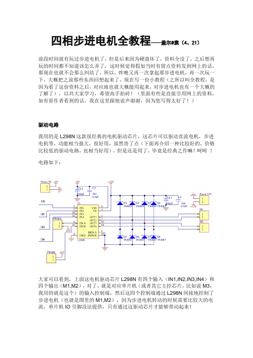
四相步进电机全教程——盖尔@袁(4、21)前段时间就有玩过步进电机了,但是后来因为硬盘坏了,资料全没了,之后想再玩的时间都不知道该怎么弄了,这时候觉得假如当时有留点资料发到网上的话,那现在也就不会那么纠结了,所以,昨晚又再一次拿起那步进电机,再一次玩一下,大概把之前那些东西回想起来了,现在写一份小教程(之所以叫全教程,是因为看了这份资料之后,对应地也就大概能用起来,对步进电机也有一个大概的了解了),以共大家学习,希望高手拍砖!(里面有些是直接引用网上的资料,如有原作者看到的话,我在这里跟他说声谢谢,因为您写得太好了!)驱动电路我用的是L298N这款很经典的电机驱动芯片,这芯片可以驱动直流电机,步进电机等,功能相当强大,很好用,虽然贵了点(下面再介绍一种比较好的,价格比较低的驱动电路,也相当好用),但是还是用了,毕竟是经典之作嘛!呵呵!电路如下:大家可以看到,上面这电机驱动芯片L298N有四个输入(IN1,IN2,IN3,IN4)和四个输出(M1,M2),对了,就是对应单片机(或者其它主控芯片,比如说M3,我用的就是这个)的输入控制端,然后这四个控制端通过L298N间接地控制了步进电机(也就是图里的M1,M2),因为步进电机转动的时候需要比较大的电流,单片机IO引脚没法提供,只有通过这驱动芯片才能够带动起来!电路里面还有PWMA和PWMB,这是使能端,用于使能M1和M2是否被输入控制的,高电平有效!一般我们假如需要控制的话,这个就接单片机的IO引脚上,假如不需要独立控制的话那直接接高电平就行了!另外,大家可以看到电路里面还有一个5V的输入,具体这个是做什么的我也不是很清楚,不过照给就是了,没问题的!好,首先先把这电路焊出来,记得,因为L298N工作的时候电流比较大,所以要求必需加上一个散热片,这样有利于保护电路不会因为过热而烧了!这里有一个小知识跟大家说一下,焊电路最好是加上一个电源指示灯,这样的好处多多,可以防止电源接反而完全不知!OK,这个方案介绍完了,下面介绍另一种成本比较低的驱动方案!假如手头上有ULN2003的话,也可以用来当成驱动电路用,我们只要知道驱动电路的作用就是放大那个电流,那任何一种能够放大电流的方法都可以拿过来用,包括你用三极管都行!下面提供一个三极管的驱动电路!至于ULN2003,具体电路我就不说了!很简单的,看下芯片的PDF就知道了。
STK672-040-E;中文规格书,Datasheet资料

STK672-040-EOverviewThe STK672-040-E is a stepping motor driver hybrid IC that uses power MOSFETs in the output stage. It includes a built-in microstepping controller and is based on a unipolar constant-current PWM system. The STK672-040-E supports application simplification and standardization by providing a built-in 4 phase distribution stepping motor controller. It supports five excitation methods: 2 phase, 1-2 phase, W1-2 phase, 2W1-2 phase, and 4W1-2 phase excitations, and can provide control of the basic stepping angle of the stepping motor divided into 1/16 step units. It also allows the motor speed to be controlled with only a clock signal.The use of this hybrid IC allows designers to implement systems that provide high motor torques, low vibration levels, low noise, fast response, and high-efficiency drive.Applications• Facsimile stepping motor drive (send and receive)• Paper feed and optical system stepping motor drive in copiers • Laser printer drum drive• Printer carriage stepping motor drive • X-Y plotter pen drive• Other stepping motor applicationsNote*: Conditions: V CC 1 = 24V, I OH = 1.5A, 2W1-2 excitation mode.Thick-Film Hybrid ICUnipolar Constant-current Chopper (external excitation PWM) Circuit with Built-in Microstepping ControllerStepping Motor Driver (sine wave drive) Output Current 1.5A (no heat sink*)Features• Can implement stepping motor drive systems simply by providing a DC power supply and a clock pulse generator.<Control Block Features>• One of five drive types can be selected with the drive mode settings (M1, M2, and M3)1) 2 phase excitation drive2) 1-2 phase excitation drive3) W1-2 phase excitation drive4) 2W1-2 phase excitation drive5) 4W1-2 phase excitation drive• Provides four freely selectable modes for the vector locus during microstepping drive: circular mode, one inside mode, and two outside modes.• Phase retention even if excitation is switched.• The excitation phase state can be verified in real time using the MO1, MO2, and MOI signal output pins.• The CLK input counter block can be selected to be one of the following by the high/low setting of the M3 input pin.1) Rising edge only2) Both rising and falling edgesElectrical Characteristics at Tc = 25°C, V CC 1 = 24V, V CC 2 = 5VRatingParameters SymbolsConditionsmin typ maxunitControl supply current I CC Pin 7, with ENABLE pin held low. 4.5 15 mA Output saturation voltage Vsat R L= 15Ω (I ≈ 1.5 A) 1.4 1.9 V Average output current Ioave Load: R = 3.5Ω / L = 3.8mH For each phase, Vref ≈ 1V 0.465 0.517 0.569 AFET diode forward voltage VdfIf = 1A1.2 1.8 V[Control Inputs] V IH Except for the Vref pin 4VInput voltageV IL Except for the Vref pin 1 V I IH Except for the Vref pin 0 1 10 μA Input current I IL Except for the Vref pin125250510μA[Vref Input Pin] Input voltage V I Pin 8 0 2.5 V Input current I I Pin 81μA[Control Outputs] V OH I = –3mA, pins MOI, MO1, MO2 2.4 VOutput voltageV OL I = +3mA, pins MOI, MO1, MO20.4 V[Current Distribution Ratio (A·B)] 2W1-2, W1-2, 1-2 Vref θ = 1/8 100 % 2W1-2, W1-2 Vref θ = 2/8 92 % 2W1-2Vref θ = 3/8 83 % 2W1-2, W1-2, 1-2 Vref θ = 4/8 71 % 2W1-2 Vref θ = 5/8 55 % 2W1-2, W1-2 Vref θ = 6/8 40 % 2W1-2 Vref θ = 7/8 20 % 2Vref 100 % PWM frequencyfc374757kHzNote: A constant-voltage power supply must be used.The design target value is shown for the current distribution ratio.Package Dimensionsunit:mm (typ) 4161STK672-040-EInternal Block DiagramM 1M 2C W B C L K M 3R E T U R N R E S E T M O I M O 1M O 2E N A B L E S G P GBB A A V r e f M 5M 4V 2ITF02366Test Circuit DiagramsVsat VdfI IH , I IL Ioave, I CC , fcWhen measuring Ioave: With SW1 set to ‘a’, Vref = 1V When measuring fc: With SW1 set to ‘b’, Vref = 0V When measuring I CC : Set ENABLE lowV 2ITF02369measuring I ITF02370Power-on ResetThe application must perform a power-on reset operation when V CC 2 power is first applied to this hybrid IC. Application circuit that used 2W1-2 phase excitation (microstepping operation) mode.Setting the Motor CurrentThe motor current I OH is set by the Vref voltage on the hybrid IC pin 8. The following formula gives the relationship between I OH and Vref.I OH = × Vref/Rs, Rs: The hybrid IC internal current detection resistor (0.33Ω ±3%)Applications can use motor currents from the current (0.05 to 0.1A) set by the duty of the frequency set by the oscillator up to the limit of the allowable operating range, I OH = 1.5A31V 2=5VSGPG ITF023710AMotor current waveform A12395Printed Circuit Board Design RecommendationsThis hybrid IC has two grounds, the PG pins (pins 3 and 4) and the SG pin (pin 22). These are connected internally in the hybrid IC.Two power supplies are required: a motor drive supply and a 5V supply for the hybrid IC itself. If the ground connections for these supplies are not good, the motor current waveforms may become unstable, motor noise mayincrease, and vibration levels may increase. Use appropriate wiring for these grounds. Here we present two methods for implementing these ground connections.If the grounds for the motor drive supply and the hybrid IC 5V supply are connected in the immediate vicinity of the power supplies:• If PG and SG are shorted at the power supply, connect only the PG line to pins 3 and 4 on the hybrid IC. Also, be sure that no problems occur due to voltage drops due to common impedances. In the specifications, this must be V CC 2 ±5%.• The current waveforms will be more stable if the Vref ground is connected to pin 22. • For initial values, use 100μF or over for C1 and 10μF or over for C2.Locate C1 as close to the hybrid IC as possible, and the capacitor ground line must be as short as possible.If the grounds for the motor drive supply and the hybrid IC 5V supply are separated:• Insert a capacitor (C1) of 100μF or over as close as possible to the hybrid IC. The capacitor ground line must be as short as possible.The capacitor C2 may be included if necessary. Its ground line should also be as short as possible.ITF02372ITF02373SeparationFunctional DescriptionExternal Excitation Chopper Drive Block DescriptionV1Driver Block Basic Circuit StructureSince this hybrid IC adopts an external excitation method, no external oscillator circuit is required.When a high level is input to φA in the basic driver block circuit shown in the figure and the MOSFET is turned on, the comparator + input will go low and the comparator output will go low. Since a set signal with the PWM period will be input, the Q output will go high, and the MOSFET will be turned on as its initial value.The current I ON flowing in the MOSFET passes through L1 and generates a potential difference in Rs. Then, when the Rs potential and the Vref potential become the same, the comparator output will invert, and the reset signal Q output will invert to the low level. Then, the MOSFET will be turned off and the energy stored in L1 will be induced in L2 and the current I OFF will be regenerated to the power supply. This state will be maintained until the time when an input to the latch circuit set pin occurs.In this manner, the Q output is turned off and on repeatedly by the reset and set signals, thus implementing constant current control. The resistor and capacitor on the comparator input are spike removal circuit elements and synchronize with the PWM frequency. Since this hybrid IC uses a fixed frequency due to the external excitation method and at the same time also adopts a synchronized PWM technique, it can suppress the noise associated with holding a position when the motor is locked.Input Pin FunctionsInput Signal Functions and Timing• CLK (phase switching clock)1) Input frequency range: DC to 50kHz 2) Minimum pulse width: 10μs3) Duty: 40 to 60% (However, the minimum pulse width takes precedence when M3 is high.) 4) Pin circuit type: Built-in pull-up resistor (20k Ω, typical) CMOS Schmitt trigger structure 5) Built-in multi-stage noise rejection circuit 6) Function:- When M3 is high or open: The phase excited (driven) is advanced one step on each CLK rising edge.- When M3 is low: The phase is advanced one step by both rising and falling edges, for a total of two steps per cycle.CLK Input Acquisition Timing (M3 = Low)• CWB (Method for setting the rotation direction)1) Pin circuit type: Built-in pull-up resistor (20k Ω, typical) CMOS Schmitt trigger structure 2) Function:- When CWB is low: The motor turns in the clockwise direction.- When CWB is high: The motor turns in the counterclockwise direction.3) Notes: When M3 is low, the CWB input must not be changed for about 6.25μs before or after a rising or fallingedge on the CLK input.• RETURN (Forcible return to the origin for the currently excited phase)1) Pin circuit type: Built-in pull-up resistor (20k Ω, typical) CMOS Schmitt trigger structure 2) Built-in noise rejection circuit3) Notes: The currently excited (driven) phase can be forcibly moved to the origin by switching this input from low tohigh. Normally, if this input is unused, it must be left open or connected to V CC 2.• ENABLE (Controls the on/off state of the A, A, B, and B excitation drive outputs and selects either operating or hold as the internal state of this hybrid IC.)1) Pin circuit type: Built-in pull-up resistor (20k Ω, typical) CMOS Schmitt trigger structure 2) Function:- When ENABLE is high or open: Normal operating state- When ENABLE is low: This hybrid IC goes to the hold state and excitation drive output (motor current) isforcibly turned off. In this mode, the hybrid IC system clock is stopped and no inputs other than the reset input have any effect on the hybrid IC state.Excitation counter up/down Control output switching timingCLK input System clock Phase excitation counter clockControl output timing A06845• M1, M2, and M3 (Excitation mode and CLK input edge timing selection)1) Pin circuit type: Built-in pull-up resistor (20k Ω, typical) CMOS Schmitt trigger structurerising or falling edge.Mode Setting Acquisition Timing• M4 and M5 (Microstepping mode rotation vector locus setting)M4 1 0 1 0 M5 1 01ModeCircular1 2 3See page 11 for details on the current division ratio.• RESET (Resets all parts of the system.)1) Pin circuit type: Built-in pull-up resistor (20k Ω, typical) CMOS Schmitt trigger structure 2) Function:- All circuit states are set to their initial values by setting the RESET pin low. (Note that the pulse width must be at least 10μs.)goes to about 71% after the reset is released.3) Notes: When power is first applied to this hybrid IC, Vref must be established by applying a reset. Applicationsmust apply a power on reset when the V CC 2 power supply is first applied.• Vref (Sets the current level used as the reference for constant-current detection.) 1) Pin circuit type: Analog input structure 2) Function:- Constant-current control can be applied to the motor excitation current at 100% of the rated current by applying a voltage less than the control system power supply voltage V CC 2 minus 2.5V.- Applications can apply constant-current control proportional to the Vref voltage, with this value of 2.5V as the upper limit.Mode switching timingExcitation counter up/downCLK input System clock Mode setting M1 to M3Mode switching clock Hybrid IC internal setting state Phase excitation clock A06846ITF02273分销商库存信息: ONSEMISTK672-040-E。
STK672-040中文资料
The motor current IOH is determined by the reference voltage on pin 8 (Vref). The relationship between IOH and Vref is given by the following equation.
1 1 0 Phase 4W1-2
001
Phase 2
0 1 1 Phase W1-2 1 0 1 Phase 1-2
Rising edge only
1 1 1 Phase 2W1-2
Input ENABLE RESET
Mo1 0 0 1 1
CWB
Direction
0
Forward
1
Reverse
Active level Low Low
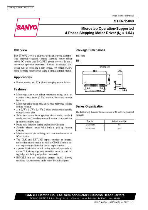
Package Dimensions
The STK672-040 is a unipolar constant-current choppertype externally-excited 4-phase stepping motor driver hybrid IC which uses MOSFET power devices. It has a microstep operation-supported 4-phase distributed controller built-in to realize a high torque, low vibration, low noise stepping motor driver using a simple control circuit.
Vref θ = 6/8
2W1-2
Vref θ = 7/8
pse0400使用手册

pse0400使用手册PSE0400是一款高品质的电子产品,为用户提供了方便实用的功能和操作方式。
本使用手册将详细介绍如何正确操作、维护和解决常见问题,以确保您能充分利用PSE0400的全部功能。
1. 基本操作:- 打开/关闭电源:按下电源按钮(位于设备的顶部/后侧)可打开或关闭电源。
- 屏幕:通过触摸屏幕上的图标来选择和操作各个功能。
- 音量调节:通过侧面的音量按钮或设置菜单中的音量选项,可调整设备的音量。
- 菜单导航:使用设备上的导航按钮或滑动屏幕,可浏览和选择不同的菜单选项。
2. 功能特点:- 多媒体播放:PSE0400支持多种音频和视频格式的播放,可通过USB接口或无线连接进行文件传输。
- 网络连接:通过Wi-Fi或移动数据网络,PSE0400可以上网浏览、下载和共享文件。
- 蓝牙连接:可以通过蓝牙与其他设备进行无线连接,如音箱、耳机、键盘等。
- 摄像功能:PSE0400内置摄像头,可拍摄照片和录制视频,并支持后期编辑和分享。
3. 维护与保养:- 清洁:定期使用干净、柔软的布将设备擦拭干净,避免使用化学溶剂。
- 保护:使用保护套和屏幕保护膜,可有效防止意外划痕和碰撞损坏。
- 更新:及时下载并安装PSE0400的软件更新,以获得最新的功能和修复错误。
4. 常见问题与故障解决:- 电池寿命较短:尝试降低屏幕亮度、关闭不必要的背景应用,以延长电池寿命。
- 触控无效:重启设备或校准屏幕触控功能。
- 无法连接到网络:检查网络设置、重新启动路由器或联系网络服务提供商等。
请按照以上内容操作和使用PSE0400,以获取最佳的使用体验。
如有更多问题或需进一步的技术支持,请参阅随附的使用手册或联系我们的客户服务部门。
祝您使用愉快!。
MOSFET、IGBT驱动芯片1TX-K D204产品手册 说明书

具备自给电源的双正激MOSFET、IGBT驱动芯片TX-KD204产品手册 V3.0 2013-06-目录一、概述 (3)二、原理框图 (3)三、电气参数 (3)3.1 极限参数 (3)3.2 驱动特性 (3)3.3 工作条件 (4)3.4 前级信号电源 (4)四、结构和尺寸 (4)4.1 外形尺寸 (4)4.2 引脚定义 (4)五、应用参考电路 (5)5.1 驱动器低压侧信号的连接 (5)5.1.1 输入信号 (5)5.1.2 前级信号电源Vc (5)5.2 驱动器高压输出侧的连接 (5)5.2.1 驱动输出功率的计算 (5)5.2.2 与IGBT的连接 (5)5.3 输出波形的测试 (6)5.4 典型应用图 (6)六、相关产品信息 (6)6.1 TX-KD202 (6)6.2 TX-KD301 (6)6.3 TX-KD (6)七、常见问题 (7)八、其它说明 (7) V3.0 2013-06-V3.0 2013-06-TX-KD204 中小功率MOSFET (IGBT )驱动器一、概述∙ 采用本公司的分时式自给电源发明专利技术 ∙ MOSFET ( IGBT)双正激隔离驱动器,卧式封装 ∙ 无需隔离电源 ∙ 工作占空比10%~90% ∙关断时输出负电平,可靠关断二、原理框图只画出单路输出三、电气参数 3.1 极限参数3.2 驱动特性除另有指定外,均为在以下条件时测得:Ta=25℃,Vdd=12V ,Fop=40kHz 。
V3.0 2013-06-3.4 前级信号电源四、结构和尺寸 4.1 外形尺寸4.2 引脚定义V3.0 2013-06- 五、应用参考电路5.1 驱动器低压侧信号的连接 5.1.1 输入信号采用自给电源技术,PWM 信号和驱动需要的能量是从同一通道送入驱动器的,因此要求前级电路的输出级具有较大的瞬时输出能力。
一般IC 无法满足要求,需要接入电流缓冲级T1和T2。
T1、T 2可用>=1.5A/40V/60MHz 的三极管,D1和D2是续流二极管,可用1N4148。
LGA-4100半导体激光气体分析仪用户手册讲解
FOCUSED PHOTONICS INC阅读说明用户须知非常感谢您选择使用本公司的LGA-4100半导体激光在线气体分析产品(以下简称:LGA-4100激光气体分析仪)。
在使用本产品前,请仔细阅读本用户手册。
本手册涵盖产品使用的各项重要信息及数据,用户必须严格遵守其规定,方可保证LGA-4100激光气体分析仪的正常运行。
同时,相关信息可帮助用户正确使用该产品,并获得准确的分析结果,节省由咨询等服务产生的额外成本。
概况本手册所介绍的产品在离厂前均经过严格的检验,以确保产品具有一流品质。
同时为了保证其安全、优质的运行,获得正确的分析结果,用户必须严格按照制造商所述使用方法进行系统操作。
另外,恰当的运输、仓储和安装及合理的操作和维护都有助于系统的安全和正常运行。
本手册详细介绍了正确使用LGA-4100激光气体分析仪的所有信息。
它为受过专门培训或具有仪器操作控制相关知识(例如自动化技术)的技术人员提供了准确的使用参考。
了解本手册所涉及的安全信息和警告信息,以及如何从技术上对错误进行修正,是对所述产品顺利进行“零危险”安装、试运转和安全运行、维护的先决条件。
只有合格的、具有专业知识的操作人员才能正确理解本手册所提到的安全信息和警告信息,并将他们运用到实际操作当中去。
由于各种原因,该手册不可能对每一产品型号都进行细节性的描述,若用户需要进一步了解相关信息,或解决本手册涉及尚浅的问题,请与当地代理商联系并要求帮助解决。
注意和警示信息本手册介绍了LGA-4100激光气体分析仪的具体应用,以及如何启动、操作和维护,可以指导用户正确地安装和操作LGA-4100激光气体分析仪,并对LGA-4100激光气体分析仪进行预防性的维护工作,以保障该系统的连续可靠运行。
需特别指出的是,本手册中的注意和警示信息至关重要(在接下来的各个章节中被强调显示,并加有适当的图标),能有效地避免不恰当的操作。
本手册所述产品的开发、制造、测试都把适当的安全标准放在首位。
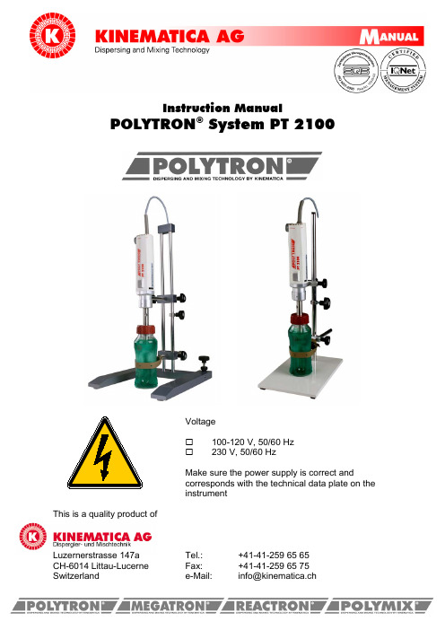
Kinematica Polytron PT 2100 说明书
Instruction ManualPOLYTRON® System PT 2100Voltage☐100-120 V, 50/60 Hz☐230 V, 50/60 HzMake sure the power supply is correct andcorresponds with the technical data plate on theinstrumentThis is a quality product ofLuzernerstrasse 147a Tel.: +41-41-259 65 65CH-6014 Littau-Lucerne Fax: +41-41-259 65 75CONTENTS: ____________PAGE:1 DESCRIPTION (4)1.1 SCOPE (4)1.2 PURPOSE (4)DRIVE UNIT PT-MR 2100 .....................................................................................................2 POLYTRON 42.1 SPECIFICATIONS/TECHNICAL DATA (4)2.2 TAKING INTO OPERATION (5)2.3 CONNECTION OF POLYTRON-AGGREGATES (6)3 POLYTRON-DISPERSING AGGREGATES (7)3.1 WORKING WITH POLYTRON 8-AGGREGATES ...................................................................................4 APPLICATION (9)4.1 WORKING AND SPEED CONTROL (9)4.2 OVERLOAD PROTECTION (10)5 MAINTENANCE (10)5.1 MAINTENANCE OF THE DRIVE MOTOR PT2100 (10)5.2 REPLACEMENT OF CARBON BRUSHES (10)-AGGREGATES ................................................. 5.3 MAINTENANCE AND CLEANING OF POLYTRON 11-AGGREGATES .............................................................................. 5.3.1 CLEANING OF POLYTRON 12 5.3.2 CORROSION (12)5.3.3 CLEANING WITHOUT DISASSEMBLY (13)5.3.4 STERILISATION WITHOUT DISASSEMBLY (13)5.3.5 CLEANING AND STERILISATION WITH DISASSEMBLY (13)5.4 DISASSEMBLY INSTRUCTIONS (14)5.5 ASSEMBLY INSTRUCTIONS (16)6 GENERAL ACCESSORY (16)6.1 STANDS (17)6.2 ASSEMBLY OF STANDS (17)6.3 ACCESSORIES TO STANDS (18)7 WARRANTY (19)With this POLYTRON ® dispersing instrument you have bought a product of highest quality - we congratulate you on this choice.To insure greatest satisfaction with your new POLYTRON ® instrument we kindly ask you to read the instruction manual before putting the unit in operation. This will help you to avoid mistakes and thus damages. POLYTRON ®instruments need little maintenance - however do not dispense you from certain checks and, especially, good cleaning.1 Description1.1 ScopeThis manual describes operation of the KINEMATICA POLYTRON PT 2100 Homogenizer and provides information on installation, maintenance, parts and accessories.1.2 PurposePOLYTRON PT 2100 units are designed to homogenise, emulsify, blend and mix small to medium quantities of organic and inorganic materials. Thanks to their small-aggregates can even reach to bottom of small test tubes. diameter, POLYTRON2 POLYTRON Drive Unit PT-MR 21002.1 Specifications / Technical DataPOLYTRON PT 2100 systems are consisting of:•Motor drive PT-MR 2100•Support rod with motor holder (not yet mounted)•Cable with plug (CH,EU or US)Motor and speed controller are one unit. This consists of:•speed controller and stabiliser•control for soft-start•fuse protection (approx. 75 – 85 dB (A) at max. speed)•safety quick coupling for POLYTRON dispersing aggregates2.2 Taking into operation• Make sure that the electric voltage of the instrument and the power supply correspond• Do not use this instrument in hazardous area• The POLYTRON PT 2100 is not designed for continous working• The recommended maximal uninterrupted working time should not exceed 20 minutes• POLYTRON dispersion aggregates must never run without liquid – the lower slide bearing is cooled and lubricated by the liquid phase of the treated medium• Make sure that the dispersion aggregates are properly cleaned after every use• Never touch a spinning rotor, nor shaft, nor the motor side coupling parts• Working with high speeds makes it possible that a noise of 85 dB A is exceeded. The user shall undertake necessary steps for protection.Before taking the instrument into operation the separately supplied support rod has to be installed on the backside of the drive motor. The necessary key is supplied as well. Make sure that the rod is properly fixed.It is recommended to run new aggregates in water for approx. 15 min.2.3 Connection of POLYTRON-AggregatesThe connection of aggregates is effected without tools by a safety quick-coupling.The aggregate has to be inserted into the motor-side coupling and slightly turn into istcorrect position only – until you hear a clear “click”.For de-connection of the aggregate simply press the coupling ring towards the frontand pull the aggregate off.When moving the coupling ring the Array aggregate can fall off the coupling. Hold thedispersing tool when de-coupling and avoidinjury of recipients, stand or working bench.3 POLYTRON-Dispersing aggregatesKINEMATICA dispersion tools are called POLYTRON aggregates. They are manufactured in a variety of different forms and recommended according the dispersion problem.The POLYTRON PT 2100 is designed to work with all POLYTRON D-Coupling aggregates with diameters of 5 to 20 mm. Please see the actually valid price list for detailed order codes.•POLYTRON -EC-Aggregate are based on the Rotor/Stator-Technology and are classic KINEMATICA products.•EC-Aggregate, EC stand for EasyClean, can be disassembled for cleaning very easily. In addition to that, they can be sterilised as per all standardmethods, also autoclaved.•The are double beared be means of RULON-slide bearings. This material convinces by ist extraordinary chemical resistance and mechanicalcharacteristics.•All aggregate are equipped with saw-teeth which efficiently accelerate the pre-cutting out your sample material.•The stator teeth are connected to each-other by a safety ring what avoids their bending also if working with hard and high viscous materials.3.1 Working with POLYTRON -AggregatesThe optimal immersion depth of the aggregate is approx. 2/3 below the liquid surface and 1/3 above the bottom of the beaker. The lower edge of the lower cleaning hole has to be immersed. B inclined immersion in an angle of approx. 15° the efficiency of the aggregate can be further improved.The maximum immersion depth is approx. 30 mm below the coupling flange.• POLYTRON dispersion aggregates must not be used dry – the lower slide bearing is cooled and lubricated by the liquid phase of the treated medium• At certain rotor speeds, depending on viscosity and volume of the treated medium, resonances and vibrations may appear. Please avoid these delicate speeds.• Working with high speeds makes it possible that a noise above 70 (<85) dB (A) is exceeded. The user shall undertake necessary steps for protection.• Make sure that the dispersion aggregates are properly cleaned after every use• Never touch a spinning rotor, nor shaft, nor the motor side coupling parts• Never let a POLYTRON -aggregate touch the bottom of the vessel4 Application4.1 Working and Speed controlDrive and control electronics are in the same housing. As first step please check the mains and run a test with no aggregate by switching ON the main switch on the front of the drive. The speed is selected by the control knob on the left side (from front) of the drive motor.For reaching the best possible effects of a POLYTRON PT 2100 the rotor speed should be adapted to the dispersion problem. Depending on product different individual speeds are optimal.IMPORTANT:The maximum rotor speed depends on the kind of sample andist viscosity. The speed is reduced in case of increasingviscosity in order to protect the drive from overload. Is theviscosity to high, the motor is stopping automatically. Anelectronic control system avoids injury of the motor drive.4.2 Overload ProtectionIs the motor overloaded the power supply is cut-off automatically. In this case switch off the main switch to “0”, disconnect the aggregate and re-start the instrument as fast as possible, without load, in order to accelerate cooling by the built-in fan. Often release of the overload fuse indicated a general overload of the instrument.5 Maintenance5.1 Maintenance of the drive motor PT 2100The motor needs no maintenance. There are no serviceable parts inside which can be repaired by the user. The only exceptions are the carbon brushes. In case of failure, please contact KINEMATICA or your supplier.by specialised staff of our “Authorised ServiceCentres” only•Use approved original spare parts only5.2 Replacement of Carbon BrushesThe replacement of the carbon brushes can be effected after disconnection of all electric supplies.•disconnet main power supplyThe motor housing has to be opened.♦Remove control knob (1/2) with cross-slotted screw driver. Fix the knob with one hand and carefully release the centric screw.♦Remove the upper part of the housing (3) by relaeasing the Philips screw (4)♦Remove the carbon brushes (5) with adequate tool and replace both. Use approved original spare parts only and exchange carbon brushes pair-wise ♦Remount housing part and control knob♦Take the drive into operation as per this instruction manual and let it run at low speed during approx. 10 minWeak sparking of brushes is a sign for well run in or flawless carbon brushes. If strong sparking occurs, relieve or switch off motor and exchange carbon brushes, otherwise the collector can be damaged.5.3 Maintenance and Cleaning of POLYTRON -Aggregates•Please carefully read the instructions regarding cleaning, disassembly and assembly in chapter 5.5 and 5.6 of this manualThe POLYTRON -Aggregates are precision built instruments and with proper care and maintenance they will provide years of trouble free operation.All POLYTRON PT-DA 21../2EC dispersion tools are EasyClean models. The can be autoclaved as a complete assembly and need not to be disassembled. However, if it is necessary to the aggregate for special cleaning or replacement of the bearings, then follow the disassembly instructions.5.3.1 Cleaning of POLYTRON -aggregatesPOLYTRON dispersion aggregates are producted especially for the application in food industry, chemistry, pharmacy, for colours and varnishes etc. and made of resistant material.All parts which are in contact with the product are generally made of fine steel in the quality of V4A, 316L, 1.4531 or the like. KINEMATICA also supplies aggregates of high-alloyed material, e.g. titanium, Hastelloy etc.Both parts of the double bearing consist of PTFE resp. RULON, besides, it does without a shaft seal. For cleaning and sterilisation we suggest to take those aggregates off.5.3.2 CorrosionUnfortunately, stainless fine steel (1.4435, 1.4571, 316L) does not mean that the material is corrosion proof. Certain chemicals can seriously attack this material.For further relevant information please check with steel keys or contact KINEMATICA AG.•All corrosive agents should be only for a very shorttime in contact with the fine steel. Make sure theydo not dry out on the metal.always properly cleaned after every use. Neutraliselye solutions and acids.•Always clean your POLYTRON -aggregateimmediaately after every use. Only well maintainedand cleaned instruments guarantee a trouble-freeservie•Protect the ball bearing in the coupling flange andall coupling parts from contact with aggressiveagents5.3.3 Cleaning without disassemblyThe easiest way of cleaning is by running the aggregate in an adequate solvent, water or a rinsing solution, using a suitable vessel or under a stream.Likewise, cleaning in an ultrasonic bath is often used and very effective. KINEMATICA offers special POLYMIX -ultrasonic baths, which are designed to clean four aggregates at the same time. Please ask for the respective brochures. 5.3.4 Sterilisation without disassembly•Wet-sterilisationAll POLYTRON aggregates can be sterilised by running them in the corresponding medium.•AutoclavingAutoclaving can be effected in assembled state, too.5.3.5 Cleaning and sterilisation with disassemblyEasyClean-Aggregates are specially designed for this method.This is easiest done with the POLYTRON EC aggregates. Disassembly is possible with a few manipulations; all parts can be cleaned resp. sterilised in the ultrasonic cleaning baths, autoclaves etc.5.4 Disassembly InstructionsThe only parts of the aggregate which have to be replaced from time to time are the bearings. The need to replace the bearings can be easily checked by the following procedure. Turn the aggregate upside down so the rotor/stator part faces up. If the inner part of the aggregate, the rotor shaft with the rotor, falls out of the outer shaft tube with stator, the bearings have to be replaced.Do not use the aggregate until new bearings are installed.5.5 Assembly Instructions6 General AccessoryIn the actual price list you will find a complete overview on available accessories and tools.Specially recommended are the clover-leaf shaped homogenizing vessels – an exclusivity of KINEMATICA. Thanks to their extraordinary flow geometric they help saving time and can further improve the efficiency.6.1 StandsThe POLYTRON PT 2100 is normally supplied with a stand as per our choice. It is important that the instruments is safely fixed to an adequate stand as ist centre of gravity is relatively high.•Please make sure that stable and safe stands andfixations are used onlyand cannot move downwards. Insufficient fixation maycause damage of the instrument and injure the user, thesample, the bench or other instruments•Fix the safety positioning ring (Option) prior to use in orderto avoid moving of the motor-drive6.2 Assembly of standsSee enclosed assembly instruction.6.3 Accessories to standsOrder. Nr. Type Description11040015 ST-P11/600Plate stand (one rod design)11040020 ST-F20/600H-shape feet stand11040051 ST-P20/600Plate stand (two rod design)Options:11045010 V essel holder with boss head for ST-P11/600 11045011 Vessel holder with boss head forST-F20/600 / ST-P20/60011045030 Safety positioning ring for ST-P11/600 11045031 Safety positioning ring for ST-F20/600 / ST-P20/600SliderBoss headSafety ringColumn/RodVessel holderH-shaped footStand plate7 WarrantyThis KINEMATICA AG instrument is warranted to be free from defects in material and workmanship for a period of 12 months from the date of delivery.KINEMATICA AG will repair or replace free of charge the defect parts which were found defective upon receipt if an inspection finds that the defect is due to materials or workmanship.This warranty does not include normal wear from use; it does not apply to any instrument or part which has been altered by anyone other than an employee of KINEMATICA AG or its designated representative nor to any instrument which has been damaged through accident, negligence, failure to follow operating instructions, the use of electric currents or circuits other than those specified in this manual, misuse or abuse.KINEMATICA AG reserves the right to change, alter, modify or improve any of its instruments without obligation to make corresponding changes to any instrument previously sold.In case of technical problems, in need of spare parts or advice please contact our regional appointed agent or directly ourselves at:KINEMATICA AGLuzernerstr. 147a Tel.: +41-41-259 65 65CH-6014 Littau-Lucerne Fax: +41-41-259 65 75Switzerland e-mail: ************************。
HA0050S HT672A使用程序
HT672A 使用程序文件编码:HA0050s简介:适用于所有的HOLTEK复杂口系列单片机。
功能说明:接收射频信号进行解码及校验。
DRIVE程序使用说明:1. 按选定的控制IC的情况进行资源分配,在rfdrive.inc文件中做修改。
在子程序CRC_CHECK中已对供应商、代理商、客户代码进行了检测。
用户必须在.inc文件中将已知的数据修改进去。
在该例程中其数据为:01H、04H、07H.2. 在自己的MAIN程序中可直接调用两个子程序及两个宏程序(参考例程MAIN.ASM)3. 将RFDRIVE.ASM程序加入到项目中4. 在调用子程序之前必须对相关寄存器进行初始化5. initial子程序用户必须针对实际情况进行编写6. 子程序CRC_CHECK只能与DECODE_RF配合使用资源占用:DECODE_RF子程序:1. ROM空间882. RAM空间25.3(其中有16个为与CRC_CHECK子程序复用)3.一个外部中断4.一个16位的计数器5.一层堆栈6.入口参数无7.出口参数YCARD(有无卡标志位)、寄存器card_no0~card_noF(存放卡号)CRC_CHECK子程序:1. ROM空间1022. RAM空间22(其中有16个为与DECODE_RF子程序复用)3. MP指针4.入口参数无5.出口参数R_CRC(CRC校验是否正确标志位)、寄存器card_no0~card_noF(存放排序正确的卡号)使用情况:1.调用子程序INCEPTANDDECODE_RF进行收卡及解码所花的时间T与信号数据的频率F成反比。
当接收的信号频率在3K左右时需要耗时6ms左右。
2.在进行CRC校验时,需要耗时1.2ms~6ms左右。
3.另注本案是在Oscillator为4MHz的情况下调试的结果;--------------------------------------------------------------; FILENAME : MAIN.ASM; AUTHOR : KELVEN; DATE : 2001/8/20; OBJECTIVE : lead the way to use the driver; CONTROLLER: HT48R50A-1; 控制线接线 :; RF PB.3;------#define main_asminclude ht48r50a-1.incinclude drive.inccode .section at 0000 'code'00horgstartjmp;中断入口地址04horgdo_waijmp08horgreti0chorgjmpdo_int ;有time1中断发生start:;程序初始化callinitRFenable_rf;enable;调用收接码程序inceptanddecode_rfcall;判断是否有卡进入,有卡去执行one程序段,j_sign ycard,one,two;无则去two程序段one:jmp start ;无卡进入;此处重新开始two:crc_check ;有卡进入,进入CRC校验步骤callj_sign r_crc,three,four ;卡号正确去执行three程序段,反之则去four程序段three:;CRC校验不正确;此处重新开始jmpagaafour:clr pcc.3clr pc.3agaa:startjmp;主程序结束;-------------------------------------------------;--------------------------------------------------------------; FILENAME: RFDRIVE.ASM; AUTHOR: KELVEN; DATE: 2002/6/19; USAGE: PUT THIS PROGRAM IN YOUR PROJECT ; ;-------------------------#define decode_asminclude ht48r50a-1.incinclude drive.incpublic inceptanddecode_rfpublic crc_checkpublic decode_1public initpublic do_intpublic do_waiht48code .section 'code'inceptanddecode_rf procclr ycardmov a, 06fhmov ccard, afintcsetmov a, 03h ;外部中断、主中断开放mov intcc, aa,80h ;TMR1采用内部计数movtimerc,amoviddatac ;DATA的入口set;------------------;如果两个中断信号时间差超过874us,则视为无效中断;程序跳出循环,由缓存器ccard来做判断。
STK672-040驱动芯片产品使用手册

STK672-040四相五线步进电机驱动器产品使用手册【简要说明】一、尺寸:长86mmX宽52mmX高23mm二、主要器件:STK672-040四相步进电动机驱动器电压:输入电源直流5V ,控制电压由负载电机决定电压范围10V~45V电流:最大输出电流2.2A三、特点:1、接线方式简单。
2、可由单片机直接控制。
3、抗干扰能力强4、大散热片散热效率高5、可单独控制一台四相五线步进电机6、可以实现最高16细分7、外部连线采用旋转压接端子,使接线更牢固。
8、具有指示灯。
适用场合:单片机学习、电子竞赛、产品开发、毕业设计。
注意啦:本产品提供例程。
【标注图片】【接线图】【原理图】【PCB图】【元件清单】【真值表】【细分调节表】【步进电机测试程序】说明:以AT89S52单片机控制单元,C语言编程!【接线图】【测试程序】/********************************************************************汇诚科技实现功能:STK672-040四相步进电机驱动测试程序使用芯片:AT89S52 或者 STC89C52晶振:11.0592MHZ编译环境:Keil作者:zhangxinchunleo淘宝店:汇诚科技【声明】此程序仅用于学习与参考,引用请注明版权和作者信息!*********************************************************************/ /******************************************************************** 程序说明:当单片机P2.0口得到一个低电平信号时,步进电机正转;当单片机P2.1口得到一个低电平信号时,步进电机反转;当单片机P2.2口得到一个低电平信号时,步进电机加速运转;当单片机P2.3口得到一个低电平信号时,步进电机减速运转;*********************************************************************/#include<reg52.h>#define uchar unsigned char#define uint unsigned intuchar Y=10; //初始化速度/********************************************************控制位定义********************************************************/sbit shi_neng=P1^0; // 使能控制位sbit fang_xiang=P1^1;// 旋转方向控制位sbit mai_chong=P1^2; // 脉冲控制位sbit zheng_zhuan=P2^0; // 正转sbit fan_zhuan=P2^1; // 反转sbit jia_su=P2^2; // 加速sbit jian_su=P2^3; // 减速/********************************************************延时函数********************************************************/ void delay(uchar i)//延时函数{uchar j,k;for(j=0;j<i;j++)for(k=0;k<180;k++);}/********************************************************加速函数********************************************************/ void jia(){Y=Y-1;if(Y<=1){Y=1;}//如果速度值小于等于1,值保持不变}/********************************************************减速函数********************************************************/ void jian(){Y=Y+1;if(Y>=100){Y=100;}}/********************************************************主函数********************************************************/main(){shi_neng=0; // 使能控制位fang_xiang=1;// 旋转方向控制位mai_chong=1; // 脉冲控制位while(1){if(zheng_zhuan==0){shi_neng=1;fang_xiang=1;}if(fan_zhuan==0){shi_neng=1;fang_xiang=0;}if(jia_su==0){delay(10);while(!jia_su);jia();}if(jian_su==0){delay(10);while(!jian_su);jian();}mai_chong=~mai_chong; //输出时钟脉冲delay(Y); //延时(括号内数值越小,电机转动速度越快)}}/********************************************************结束********************************************************/【图片展示】。
- 1、下载文档前请自行甄别文档内容的完整性,平台不提供额外的编辑、内容补充、找答案等附加服务。
- 2、"仅部分预览"的文档,不可在线预览部分如存在完整性等问题,可反馈申请退款(可完整预览的文档不适用该条件!)。
- 3、如文档侵犯您的权益,请联系客服反馈,我们会尽快为您处理(人工客服工作时间:9:00-18:30)。
STK672-040四相五线步进电机驱动器产品使用手册
【简要说明】
一、尺寸:长86mmX宽52mmX高23mm
二、主要器件:STK672-040四相步进电动机驱动器
电压:输入电源直流5V ,控制电压由负载电机决定电压范围10V~45V
电流:最大输出电流2.2A
三、特点:
1、接线方式简单。
2、可由单片机直接控制。
3、抗干扰能力强
4、大散热片散热效率高
5、可单独控制一台四相五线步进电机
6、可以实现最高16细分
7、外部连线采用旋转压接端子,使接线更牢固。
8、具有指示灯。
适用场合:单片机学习、电子竞赛、产品开发、毕业设计。
注意啦:本产品提供例程。
【标注图片】
【接线图】
【原理图】
【PCB图】
【元件清单】
【真值表】
【细分调节表】
【步进电机测试程序】
说明:以AT89S52单片机控制单元,C语言编程!
【接线图】
【测试程序】
/********************************************************************
汇诚科技
实现功能:STK672-040四相步进电机驱动测试程序
使用芯片:AT89S52 或者 STC89C52
晶振:11.0592MHZ
编译环境:Keil
作者:zhangxinchunleo
淘宝店:汇诚科技
【声明】此程序仅用于学习与参考,引用请注明版权和作者信息!
*********************************************************************/ /******************************************************************** 程序说明:
当单片机P2.0口得到一个低电平信号时,步进电机正转;
当单片机P2.1口得到一个低电平信号时,步进电机反转;
当单片机P2.2口得到一个低电平信号时,步进电机加速运转;
当单片机P2.3口得到一个低电平信号时,步进电机减速运转;
*********************************************************************/
#include<reg52.h>
#define uchar unsigned char
#define uint unsigned int
uchar Y=10; //初始化速度
/********************************************************
控制位定义
********************************************************/
sbit shi_neng=P1^0; // 使能控制位
sbit fang_xiang=P1^1;// 旋转方向控制位
sbit mai_chong=P1^2; // 脉冲控制位
sbit zheng_zhuan=P2^0; // 正转
sbit fan_zhuan=P2^1; // 反转
sbit jia_su=P2^2; // 加速
sbit jian_su=P2^3; // 减速
/********************************************************
延时函数
********************************************************/ void delay(uchar i)//延时函数
{
uchar j,k;
for(j=0;j<i;j++)
for(k=0;k<180;k++);
}
/********************************************************
加速函数
********************************************************/ void jia()
{
Y=Y-1;
if(Y<=1){Y=1;}//如果速度值小于等于1,值保持不变
}
/********************************************************
减速函数
********************************************************/ void jian()
{
Y=Y+1;
if(Y>=100){Y=100;}
}
/********************************************************
主函数
********************************************************/
main()
{
shi_neng=0; // 使能控制位
fang_xiang=1;// 旋转方向控制位
mai_chong=1; // 脉冲控制位
while(1)
{
if(zheng_zhuan==0){shi_neng=1;fang_xiang=1;}
if(fan_zhuan==0){shi_neng=1;fang_xiang=0;}
if(jia_su==0){delay(10);while(!jia_su);jia();}
if(jian_su==0){delay(10);while(!jian_su);jian();}
mai_chong=~mai_chong; //输出时钟脉冲
delay(Y); //延时(括号内数值越小,电机转动速度越快)
}
}
/********************************************************
结束
********************************************************/
【图片展示】。
