(完整版)建筑毕业设计-英文翻译
毕业设计中英文翻译【范本模板】
英文The road (highway)The road is one kind of linear construction used for travel。
It is made of the roadbed,the road surface, the bridge, the culvert and the tunnel. In addition, it also has the crossing of lines, the protective project and the traffic engineering and the route facility。
The roadbed is the base of road surface, road shoulder,side slope, side ditch foundations. It is stone material structure, which is designed according to route's plane position .The roadbed, as the base of travel, must guarantee that it has the enough intensity and the stability that can prevent the water and other natural disaster from corroding.The road surface is the surface of road. It is single or complex structure built with mixture。
The road surface require being smooth,having enough intensity,good stability and anti—slippery function. The quality of road surface directly affects the safe, comfort and the traffic。
(完整版)建筑外文翻译毕业设计论文

随着我国经济的发展,建筑行业已经朝着多元化方向发展,建筑行业在我国经济发展中起着非常重要的作用。
而建筑工程管理工作直接关系到工程的质量、成本管理、人员的安全、企业的经营效益,甚至关系到企业的生死存亡,但是我国建筑工程管理在现阶段存在许多的不足:管理体制不健全。
我国大部分的建筑工程为了节约人员开支,减少了建筑工程管理机构的人员数量和质量。
管理制度深入性不足。
建筑行业的相关管理制度都是由一些著名的建筑行业专家等共同研究制定的,但是在各建筑单位中就只是一张纸,他们也都只是为了应付上级的检查,并不能应用到建筑工程管理上。
在我国建筑工程管理工作中,难以全面确立我国建筑工程管理思路体系,主要是因为我国缺乏管理理论和经验。
建立建筑工程管理思路体系是专业性较强的问题,其实施必须由资深的建筑学科专家和具有丰富工作经验的管理人员来组织,只有这样才能实现。
国外建筑行业无论是技术还是理论都比较先进,因此我国在建筑工程管理思路体系的建立过程中,必须借鉴国外的先进理念,另外,还必须吸取先进的建筑工程管理方法,并对各方面的资料加以综合和整体。
总之,要想确保我国建筑工程管理工作的有序进行,必须以健全的工程管理思路体系作为建筑工程总体管理水平提升的基本保障。
加强施工质量管理,建立合理可行的质量保证体系,将工程的质量工作落到实处。
工程施工企业要根据质量保证体系,形成行之有效的质量保证系统,树立质量方针,从而让其更加有指令性、系统性及可操作性。
要将人、材料和机械各个要素有效结合起来。
首先,人是质量控制的核心,要把人作为控制的推动力,充分调动人的积极性,树立工程质量第一的观念。
其次,施工材料作为建筑产品的主体,对材料质量的控制是工程质量控制的关键。
最后,工程施工的机械是进行施工机械化的主要标志,对现代化项目施工起到不可缺少的作用,它直接影响了施工项目的进度和质量,所以,选好用好工程机械设备非常重要。
所以,应该根据工程项目的具体特点,综合考虑各种环境因素,实施有效的施工现场控制,为保证施工质量及安全创造良好的外部条件。
建筑学毕业外文翻译

(2016届)毕业设计文献翻译题目:姓名:学院:专业:建筑学班级:学号:指导教师:导师学科:导师职称:教务处制年月日嘉兴学院外文文献翻译译文1外文题目:Analysis of and Study on the Difficulties in the Fire ProtectionDesign of Large Commercial Complex专业班级:学生姓名:学号:一、外文原文AbstractFire properties of the large commercial complex has been summarized. Based on the fact that there are contradictions between what is required for the large commercial complex in the fire code and the real application in practice, difficulties in fire protection of designing large commercial complex have been analyzed.Key words:large commercial complex; fire protection design; difficulty; research status 1. IntroductionIn recent years, more and more large commercial complexes have appeared in China. These complexes integrate different businesses into on large building, where customers can do shopping, eat or enjoy themselves. According to the statistics, nearly 200 large complexes in China now have indoor walking street, with different kinds of shops standing along both sides. And what’s more, the indoor walking street shares the large space with the atrium.Generally speaking, the large commercial complex is multi-functional with high fire load and large assembly of people. The mechanism of the occurrence of fire is different from that of the ordinary buildings and the fire loss is also heavier. As a result, this kind of commercial complex needs higher fire safety. However, the current national fire code only gives the minimum requirements. No specific fire safety objectives are provided. Therefore, it is quite important to understand the design and research status of the large commercial complex and to provide safe, reasonable and economical fire design method.2.Characteristics of large commercial complex fire2.1 High fire occurrenceThere are heavy fire loads inside the large commercial complex, which include merchandises like clothes, shoes, hats and combustible decorations. It is widely recognized that electricity is the important factor to cause fire hazard. Therefore, to provide electricity among these combustibles is very dangerous. However, in the large commercial complex, electric systems and equipment are installed to provide electricity for lighting, ventilating and air conditioning. If there is short circuit, spark, poor contact or long time electrifying of the lights or electric heater, fire may be caused. In addition, other factors like improper welding, lighted cigarette ends or arson can cause fire too. 2.2 Quick spread of fire and smokeIf fire occurs in a large commercial complex, it can spread very quickly and grow into a large fire in a short time, while the shelter of the rack usually decrease the sensitivity of the fire detection system and cause delay. As a result, fire can’t be detected and controlled timely. The other reason for quick fire spreading is that the vertical space formed by the atrium and escalators in the complex may help fire and smoke to spread to the whole building.2.3 Large casualties and property lossThe large commercial complex usually accommodates valuable merchandises and facilities. Once there is a fire, big property loss is inevitable. And what’s more fatal is that there are usually large assemblies present. The heavy smoke with CO, CO2, NOx, HCN not only affects the safe and quick evacuation of the people, but also put them in danger. According to the statistics of Japan and UK, the percentage of deaths caused by suffocation in the fire can be as high as 78.9%. As a result of a complicated layout, large assembly of people, long time to evacuate, the large commercial complex is susceptible to fatal fire accidents which usually suffer heavy casualties. For example, on Sept. 30, 1997, a fire occurred in a supermarket on the third floor of a shopping mall in Changchun, Jilin province. It caused 11 deaths and 2 injuries. The burning area reached 4500m2 andmost of the commodities inside the supermarket were burnt. The direct property loss was RMB 14,611,000 Yuan.3.Analysis of difficulties in fire protection design of large commercial complexComparing with the ordinary building, the commercial complex is large and usually multi-functional. During the construction, new materials, technologies and structures are employed, which often bring about difficulties in its fire protection design.3.1 There are no applicable requirements for the fire protection design of the complex in the current national fire codeFor the fire protection design of a large commercial complex, the current national standard has covered the following points:(1)the building style and the distribution of business operations inside the complex; (2 )the style of the indoor walking street;(3 )how to determine the fire load of the complex;(4)if the walking street inside the complex can be used as a safe evacuation area? If yes, what kind of conditions should be provided;(5)the occupancy density, fire fighting equipment, smoke control pattern as well as other important design parameters;(6)the size and separation of the shops along the both sides of the walking street.3.2 There are limitations in the fire code for the fire designing of the large commercial complexHere just gives an example to illustrate the limitation. The requirements for the evacuation of the people in “Code for design of shop buildings”JGJ48-88 can’t meet the need of the evacuation system of the large commercial complex. Personnel convert quantity in JGJ48-88 is based on the business area and the area of the storage, which is totally unfit for the new layout of a complex with modern ideas and novelties. The evacuation width calculated according to the method given in JGJ48-88 is usually too big. As a result, more staircases will be required, which not only brings great difficulties in the designing of the evacuation system, but also create enormous waste. At the sametime, the layout, structure as well as the aesthetic quality of the complex will be affected too.[68~70] Therefore, it is improper to determine the evacuation width or other parameters according to the calculation method given in the current standard.3.3 Some of the requirements in the current code can’t be implemented easily in the fire protection design of large commercial complex(1)Fire compartmenttion.It is required in the current fire code that the fire compartment of the commercial buildings shall not be larger than 5000m2. However, the building area of a large commercial complex is usually as big as hundreds of thousands of square meters. If the fire compartment is divided strictly according to the requirements of the fire code, many many fire compartments, staircases and exits will be provided. The result of this is that the arrangements of the business area will be greatly affected and the function of the complex will be completely limited.(2)Fire separation.The typical problem for the fire protection design of large commercial complex is that its travel distance and evacuatio n width can’t meet the requirements of the code.“Code for design of building fire protection and prevention” GB 50016-2006 requires that the linear distance between any point in the shopping areas inside the Class A and Class B buildings and the nearest exit should not be larger than 30m; when the building is protected completely by sprinkler system, the maximum safe travel distance shall be 37.5m; the end of the staircase on the first floor shall be provided with exit directly leading to outdoor or shall be enlarged. When the building is not more than 4 stories, the exit directly leading to outdoor can be located at the place that is not more than 15m away from the staircase. But in practice, it is not enough for large commercial complex to provide emergency staircases only at the periphery of the building because the complex is usually quite long and deep. Therefore, more staircases shall be provided in the middle. According to the requirements of the fire code, these staircases in the middle part of the building must have exits directly leading to the outdoor, which is completely out of the question.“Code for fire protection design of tall buildings” GB 50045-95(2005 edition) requires that the linear distance between any point in the shopping areas and the nearest exit should not be larger than 30m. In practice, the emergency staircases of the high-rise commercial buildings are also provided at the periphery of the building. The linear distance between the least favorable point to the nearest staircase is often larger than 30m. But in order to meet the requirement of the tall building code, staircases in the middle of the building must be provided. However, the staircases in the middle of the building can’t directly lead to outside.(3)Fire fighting.Both “Code for design of building fire protection and prevention” and “Code for fire protection design of tall buildings” require that where the length of the building along the street is more that 150m or the total length of the building is more than 220m, a well situated fire vehicle access shall be provided to cross the building. For large commercial complex, it is quite difficult to provide fire vehicle access to cut the building apart. Therefore, in practice, many designers propose to use the walking street as the fire vehicle access, but it can’t meet the fire fighting need of the fire vehicles.4.Current research status at home and abroadCurrently in China, the researches on the fire protection design of large commercial complex mainly focus on the analysis of some fire protection system.Zhao Hualiang analyzed the commonly used index and parameters of evacuation design. Parameters used for design of evacuation system of large commercial complex such as number of people, evacuation width, travel distance as well as emergency lighting have been discussed.Aim at the difficulties in designing of the fire partition in commercial construction, Zheng Yanqiu analyzed the general requirements for the design of the sunk plaza, fire compartment, protected evacuation passage and atrium. The application of cesium and kalium fire protection glass and toughened glass protected by water sprinkler as the fire partition was also studied.Guo Jinjun and Zhao Lijun introduced the difficulties in the designing of water based fire fighting systems as well as the solution.Guo Xiaolong and Wang Lingjian introduced a method to solve the problem of fire separation of a large commercial complex as well as atrium smoke extraction by separating inner atrium and horizontal sliding skylight.“Code for fire protection design of large commercial complex in Chongqing” provides a method to calculate the width of exit and series of parameters that are applicable for Chongqing city. In the code, the concept of calculating the width of the exit based on the fire compartment was put forward for the first time. The requirements that the exit can be borrowed or shared by the adjoining fire compartments are provided and the calculation method to calculate this kind of exit is given. For the shopping malls with quite many stories above ground, this local code of Chongqing introduces the concept of “refuge space”, which provides favorable conditions for the emergent evacuation of the people.Aiming at the problems in the requirement of the fire code-“if the building area of an underground shopping mall is larger than 20000m2, fire wall shall be used to separate it and there shall be no openings in the fire wall”, Kang Dasheng and Wang Jinling suggested to provide a so-called “open fire isolating area” (sunk space) and “closed fire isolating area” . They also suggested to provide an emergency passageway less than 55m long on the first underground floor to directly lead to the outside of the building. For those large space areas like the atrium and indoor walking street, they suggested to install intelligent sprinkler system especially for large space areas.The above mentioned researches mainly focus on the problems in the design of the commercial buildings. Solutions from the experiences during design, review and construction have been proposed, but they are not complete and thorough. The results can’t be generalized.Some foreign building and fire codes have some requirements for the fire protection of commercial buildings. For example, building code of Canada, fire code of Singapore, building code of New Zealand and the “Uniform Building Code” of NFPA etc. However,these requirements are mainly applicable to ordinary shops, not the large commercial complexes in China.5.ConclusionIn order to solve so many practical problems encountered in the fire protection design of the large commercial complex, to evaluate the fire safety performance of this kind of building scientifically, and to define the scientific, reasonable and economic fire safety system, it is necessary to study the key technology of fire protection based on the practical fire loads and occupant density in the large commercial complex in China. Through this research, the related technical requirements of fire protection design were determined, and the scientific, reasonable and economical method of fire protection design was proposed. It is very important to understand the method and to prevent the occurrence of fire so as to safeguard the life safety and reduce property loss.References[1]Fire Bureau of MPS. Anthology of disastrous fire cases of China,2008.[2]LI Yin-qing. Performance Design for Building Fire Protection. Beijing: Chemical Industry Press.2005.141~171.[3]LI Yu. Study on Performance-based Fire Protection Design of Large Sho pping Centre. MA thesis of Xi’an University of Architecture & Technology,2005.[4]ZOU He. The key technology research for performance-based design of underground commercial building. Engineering Master Degree Dissertation of Chongqing University,2007.[5]LI Xin, GU Yu. Discussion on the problems in the evacuation design of large commercial complex.. Fire Technology and Products Information,2007,12,31~33.[6]Chongqing Construction Committee. DBJ 50-054-2006 Code for fire protection design of large-scale commercial buildings of Chongqing,2006.[7]HUO Ran, YUAN Hong-yong. Performance-based Fire Protection Design and Analysis.Hefei:Anhui Science & Technology Publishing House, 2003.[8]ZHAO Wei. Evaluation of performance-based design on giant commercial building.Fire Science and Technology, 2009,28(11),817~819.[9]The Ministry of Public Security of the People’s Republic of China. GB50016-2006 Code of Design on Building Fire Protection and Prevention. Beijing: China Planning Press,2006.[10]The Ministry of Public Security of the People’s Republic of China. GB50045-95 Code for fire protection design of tall buildings(2005Edition).Beijing: China Planning Press,2005.[11]Civil Air Defence Office of China, The Ministry of Public Security of the People’s Republic of Chi na. GB 50098-2009 Code for fire protection design of civil air defense works. Beijing:China Planning Press,2009.[12]Central-south Architectural Design Institute. Code for Design of Shop Buildings(draft) JGJ 48-88. Beijing:China Architecture & Building Press,1988.[13]LIN Feng. Studies on the Fire Safe of Large-scale Commercial Buildings. MA thesis of Xi’an University of Architecture & Technology,2009.[14]ZHAO Hua-liang. Discussion on Safe Evacuation from Commercial Buildings.Fire Technology and roducts Information,2005,2,9~11.[15]JING Jian-sheng, NI Zhao-peng, ZHUANG Jing-yi. Calculation method of the number of safe egress occupants in commercial building.Fire Science and Technology,2003,22(5),351~353.[16]ZHANG Shu-ping, JING Ya-jie. Research of evacuation crowd in the business hall of large department stores. Fire Science and Technology,2004,23(2),133~136.[17]QI Xiao-xia, PAN Jing. Research of evacuation crowd in the large specialized stores. Fire Science and Technology,2005,24(1),60~64.[18]YAN Xiao-long,WANG Ling-jian. Fire protection design of large-scale commercial building. Fire Science and Technology,2007.26(5),523~525.[19]ZHENG Yan-qiu. Analysis of fire protection separate design in commercial construction [J]. Fire Science and Technology,2009,28(1),43~46.[20]GUO Jin-jun, ZHAO Li-jun. Design difficulties and solutions for water fire-extinguishing system in the mall [J]. Water & Wastewater Engineering,2008,7(34),86~88.[21]GUO Sheng-you, LIU Mei-mei. Idea and characteristic of code for the fire prevention design of large-scale commercial buildings of Chongqing [J]. Fire Science and Technology, 2007, 26(1), 49~51.[22]KANG Da-sheng, WANG Jin-ling. The Measures of Large-Scale Shop Fire Prevention Designing [J]. Journal of Chinese People's Armed Police Force Academy,2008,24(10),15~17.[23]National Research Council of Canada.National Building Code of Canada[S].2005ˈVolume 1.[24]Singapore Civil Defence Force.Singapore Fire Code[S].[25]NFPA. NFPA1 Fire Code 2009 Edition[S],2009.[26]R.L.P. Custer & B. J. Meacham. Introduction To Performance based Fire Safety. National Fire Protection Association, Quincy, MA, 1997.[27]SFPE engineering guide to performance–based fire protection:analysis and design of buildings.First Edition,National Fire Protection Association,Society of Fire Protection Engineers,USA,2000.[28]British Standards Institution. Draft British standard BSDD240 fire safety engineering in building,Part l: Guide to the application office safety engineering Principles,1997.[29]Building Code of Australia, Australia Building Code Board, October 1996.[30]Hadjisophocleous GV,Benichou N.Development of performance-based codes, performance criteria and fire safety engineering methods.International Journal on Engineering Performance-based Fire Code, 2000, 2(4), 127~142.二、翻译结果分析与研究大型商业综合体中消防难点的设计摘要总结了大型商业综合体的火灾特性。
建环毕业翻译(中英文对照)

本科毕业设计(论文)外文翻译专业名称:建筑环境与设备工程年级班级:xxx学生姓名:xx指导教师:xxxx河南理工大学土木工程学院二○一二年六月十日毕业设计外文翻译英文:How Air Conditioners Work and energy conservationtechnology researchAbstract:An air conditioner is basically a refrigerator without the insulated box. It uses the evaporation of a refrigerant, like Freon, to provide cooling. The mechanics of the Freon evaporation cycle are the same in a refrigerator as in an air conditioner.Keywords:water towers 、weather-resistant、compressor、energy conservation When the temperature outside begins to climb, many people seek the cool comfort of indoor air conditioning. Like water towers and power lines, air conditioners are one of those things that we see every day but seldom pay much attention to. Wouldn't it be nice to know how these indispensable machines work their magic? In this article, we will examine air conditioners -- from small to huge -- so you know more about what you're seeing!The Many Faces of CoolAir conditioners come in various sizes, cooling capacities and prices. One type that we see all the time is the window air conditioner.Window air conditioners are an easy and economical way to cool a small area. Most people who live in suburban areas usually have one of these in their backyard: If you live in an apartment complex, this is probably a familiar sight: Most businesses and office buildings have condensing units on their roofs, and as you fly into any airport you notice that warehouses and malls may have 10 or 20 condensing units hidden on their roofs:And then if you go around back at many hospitals, universities and office complexes, you find large cooling towers that are connected to the air conditioning system:Even though each of these machines has a pretty distinct look, they all work on the same principles. Let's take a closer look.The Basic IdeaAn air conditioner is basically a refrigerator without the insulated box. It uses the evaporation of a refrigerant, like Freon, to provide cooling. The mechanics of the Freon evaporation cycle are the same in a refrigerator as in an air conditioner. According to the Merriam-Webster Dictionary Online, the term Freon is generically "used for any of various conditioner. According to the Merriam-Webster Dictionary Online, the term Freon is generically "used for any of various nonflammable fluorocarbons used as refrigerants and as propellants for aerosols."This is how the evaporation cycle in an air conditioner works (See How Refrigerators Work for complete details on this cycle):1.The compressor compresses cool Freon gas, causing it to become hot,high-pressure Freon gas (red in the diagram above).2.This hot gas runs through a set of coils so it can dissipate its heat, and it condenses into a liquid.3.The Freon liquid runs through an expansion valve, and in the process it evaporates to become cold, low-pressure Freon gas (light blue in the diagram above).4.This cold gas runs through a set of coils that allow the gas to absorb heat and cool down the air inside the building.Mixed in with the Freon is a small amount of a light weight oil. This oil lubricates the compressor.Window UnitsA window air conditioner unit implements a complete air conditioner in a small space. The units are made small enough to fit into a standard window frame. Youclose the window down on the unit, plug the unit in and turn it on to get cool air. If you take the cover off of an unplugged window unit, you will find that it contains:A compressorAn expansion valveA hot coil (on the outside)A chilled coil (on the inside)A control unitThe fans blow air over the coils to improve their ability to dissipate heat (to the outside air) and cold (to the room being cooled).BTU and EERMost air conditioners have their capacity rated in British thermal units (BTU). Generally speaking, a BTU is the amount of heat required to raise the temperature of one pound (0.45 kg) of water 1 degree Fahrenheit (0.56 degrees Celsius). Specifically, 1 BTU equals 1,055 joules. In heating and cooling terms, 1 "ton" equals 12,000 BTU.A typical window air conditioner might be rated at 10,000 BTU. For comparison, a typical 2,000-square-foot (185.8 m2) house might have a 5-ton (60,000-BTU) air conditioning system, implying that you might need perhaps 30 BTU per square foot. (Keep in mind that these are rough estimates. To size an air conditioner for your specific needs, contact an HV AC contractor.)The energy efficiency rating (EER) of an air conditioner is its BTU rating over its wattage. For example, if a 10,000-BTU air conditioner consumes 1,200 watts, its EER is 8.3 (10,000 BTU/1,200 watts). Obviously, you would like the EER to be as high as possible, but normally a higher EER is accompanied by a higher price.Is the higher EER is worth it?Let's say that you have a choice between two 10,000-BTU units. One has an EER of 8.3 and consumes 1,200 watts, and the other has an EER of 10 and consumes 1,000 watts. Let's also say that the price difference is $100. To understand what thepayback period is on the more expensive unit, you need to know:1.Approximately how many hours per year you will be operating the unit2.How much a kilowatt-hour (kWh) costs in your areaLet's say that you plan to use the air conditioner in the summer (four months a year) and it will be operating about six hours a day. Let's also imagine that the cost in your area is $0.10/kWh. The difference in energy consumption between the two units is 200 watts, which means that every five hours the less expensive unit will consume 1 additional kWh (and therefore $0.10 more) than the more expensive unit.Assuming that there are 30 days in a month, you find that during the summer you are operating the air conditioner:Since the more expensive unit costs $100 more that means that it will take about seven years for the more expensive unit to break even.See this page for a great explanation of seasonal energy efficiency rating (SEER).Split-system UnitsA split-system air conditioner splits the hot side from the cold side of the system。
建筑学毕业设计英文翻译

建筑学毕业设计英文翻译Graduation Design of ArchitectureIntroductionThe key focus of the graduation design project is urban renewal, and the project site is located in a rundown area of the city center. The overall goal of the project is to provide a comprehensive plan for the urban renewal of this area, which is currently occupied by old and deteriorating buildings, and to create a vibrant and sustainable neighborhood.Research BackgroundUrban renewal is an ongoing challenge for many cities around the world, with a significant proportion of city centers struggling with abandoned and aging buildings. This not only results in negative visual impacts but also poses potential safety and health risks to residents. Furthermore, such areas are often perceived as unsafe, deterring investors from establishing businesses in the neighborhood. Thus, urban renewal projects are perceived not only as social projects but also as an economic tool to attract enterprises and create jobs.Design ApproachIn addressing the urban renewal challenge, the graduation design project adopts a multidisciplinary approach, which combines architecture, sustainability, and urban planning principles. The core idea is to revitalize the area and provide a multifunctional and harmonious living and working environment for residents and businesses.Design ProposalThe proposed urban renewal comprises three major components: revitalization of buildings, improvement of public spaces, and promotion of sustainable strategies.Revitalization of BuildingsThe renovation of old and deteriorating buildings and the conversion of redundant buildings into new commercial, cultural, and residential spaces is one of the main objectives of the project. These buildings will be transformed into modern, energy-efficient, and trendy spaces. The overall aim is to bring a fresh and exciting look to the area, which will enhance the liveability and attractiveness of the neighborhood.Improvement of Public SpacesPublic spaces are vital in creating a sense of community, socializing, and promoting physical activity. The project will include the creation of new parks, squares, and green spaces, which are designed to provide a balanced mix of recreational and functional spaces. This approach will encourage social interaction and physical activity while providing a safe environment for children to play.Promotion of Sustainable StrategiesSustainability is a critical aspect of the project. The proposals will include the use of renewable energy sources, the implementation of rainwater harvesting systems, green roofs, and the recycling of waste materials. These strategies are expected to contribute to the reduction of the neighborhood's carbon footprint, increasing the ecological value of the urban environment, and promoting social responsibility.ConclusionThe proposed urban renewal design for the project site addresses the challenges of a deteriorating urban center while ensuring social, economic, and environmental sustainability. This design proposal provides a comprehensive and holistic solution to urban renewal, creating a vibrant, functional, and sustainable neighborhood.。
建筑学毕业设计外文翻译

本科生毕业设计外文资料翻译专业建筑学班级092班姓名XXX指导教师XXX所在学院XXX附件 1.外文资料翻译译文;2.外文原文学校建筑规划设计漫谈在校园内的功能和各种需求亦趋向于多元化,在规划、设计中必须要找出一种合适的方法来适应、符合现在及未来的世界潮流需要。
1、学校的功能和秩序学校特别是高等学校的功能相对来说是比较复杂的,在规划设计中要充分考虑到学校中的功能分区和教学的秩序,才能做到有合理的设计和良好的规划。
教学区是校园的核心,是校园建设中的最关键的部分。
学校中的一切其它功能均是围绕其进行的。
教学区的布局主要有组团式与网络式两种主要设计方法。
组团式便于院系相对独立地组织教学活动与进行管理,更能适应建校周期较长而分期施工的现实。
“院落”是是中国传统的建筑布局形式,由建筑所围成的庭院形成社交性的公共空间,也有利于学校中的交流。
网络式的发展规划有利于不同的科系在今后的发展中专业更新与规模调整,并可灵活调节教学用房的使用性质,因此被现代的新型校园规划布局所偏爱,它利于目前国内的大学院校、院系合并和学科调整的教学改革大趋势。
学生宿舍生活区是大学校园内又一个重要的组成部分,无论改革后学生生活区社会化管理落实的力度有多大,还是由于扩招形式的“不是数着床板招生”的局面到何种程度,在目前的实际情况下,新建的大学校园仍然需要规划好学生生活区的建设。
当然要充分考虑到如何便于社会化的管理,有利于形成独立的管理系统,为以后的发展留有可能性。
2、学校的交通组织高等学校交通组织中,首要的是要体现以人为本的思想。
根据教师、学生的心理及行为方式研究各种道路组织、形态和层次,创造一个满足校园使用者的物质和精神上要求的校园环境。
现代校园要求建筑物之间能联络方便、尽量通畅、便捷。
为此,各类建筑物的设计,多采用集中式的布局,建筑群体也多以成团的方式组合,尽量减少楼间的距离几交通路线。
各个相对独立的区域之间,也尽量打通分割界限,室内外都设有方便的连廊和通道,使建筑群体在整体上能联络通畅,达到提高和保证交通、交流、传递、沟通之最佳的效率。
绿色建筑毕业设计外文翻译中英文对照(可编辑)

绿色建筑毕业设计外文翻译中英文对照(可编辑)########## 大学本科毕业设计外文资料译文年级: 2008级学号: 20087221姓名: 朱莉专业: 铁道工程指导老师:2012年6月原文:Green BuildingAbstract: Green building refers to doing its best to imizeconservation of resources energy, land, water, and wood,protecting the environment and reducing pollution in its life cycle. Providing people with healthy, appropriate and efficient use of space, and nature in harmony symbiosis buildings. I described more details of green building design’ notion, green building’ de sign, as well as the significance of the concept of green building and improving the effectivenessanalysis of the external effects of green building measures, Key words: green buildings; protect the ecology; signification ; analysing the effectsWhat is a green buildingGreen building refers to building life cycle,the imum conservation of resources energy, land, water and materials, protecting the environment and reducing pollution, providing people with healthy, appropriate and efficient use of space, and nature harmony of the buildingThe so-called green building "green" does not mean a general sense of three-dimensional green, roof garden, but represents a concept or symbol, refers to building environmentally and friendly, makes full use of natural resources, environment and basic ecological damage to the environment without balance of a building under construction, but also known as sustainable building, eco-building, back into the wild construction, energy saving construction Green building interior layout is very reasonable, to minimize the use of synthetic materials, full use of the sun, saves energy for the residents and creates almost-natural feeling People, architectures and the natural environment for the harmonious development goals, in the use of natural and artificial means to create good conditions and healthy living environment, as much as possible to control and reduce the use and destruction of the natural environment, to fully reflect the nature obtain and return balance2. the meaning of green buildingThe basic connotation of green building can be summarized as: to reduce the load on the environment architecture, which saves energy and resources; provides a safe, healthy, comfortable living space with goods; affinity with the natural environment, so that people and building's coexistence with the environment and sustainable development becomes harmonious3.Development of the significance of green building rating systemEstablish green building rating system is a revolution in the fieldof architecture and the Enlightenment, its far more than energy savings. It is innovative in many ways and organic synthesis, thereby building in harmony with nature, full utilization of resources and energy, create healthy, comfortable and beautiful living space. It's revolutionary for the field of architecture from the technical, social and economicangles3.1 Technical SignificanceGreen building study of early technical problems of individual-based, technology is isolated and one-sided, not formed an organic whole, the integration of design and economic study of consciousness is far fromthe only strategy of economic analysis phase of the subsidiary's knowledgeHowever, individual technical research results of early modern green building techniques for the multi-dimensional development and systems integration will lay a solid foundation. Since the nineties of the 20th century, with the understanding of green building gradually deepen and mature, people give up way too utopian thinking environmental consciousness and moral constraints and spontaneous green behavior, turned to explore more workable environmental philosophy, environmental and capital combined into the future world with the new direction of development of environmental protection, green building has entereda result of ecological ethics from the practice of promoting ecological research to deepen the new stage. Green Building Technology takes on the natural science, social science, humanities, computer science,information science and other subjects the trend of integration of research results, making green building design into the multi-dimensional stage of development strategy study. The deepening of green building technology strategy and development in materials, equipment, morphology and so on. Various advanced fields, in technology development, technology and other design elements of the integration is also starting from the past the simple addition, more attention to the periphery ofthe retaining structure itself design technology and architecture to combine the overall system change, gradually becoming green building systems. Green building rating system was established green building technologies gradually improve and systematize the inevitable result, it is the organic integration of green building technology, a platformbuilt to green building technology, information technology, computer technology and many other subjects can be a unified platform in their respective roles, the establishment of a comprehensive evaluation system for designers, planners, engineers and managers a more simple, Guizhangmingque green building assessment tools and design guidelines with clear rule3.2 The social significanceGreen building rating system reflects the socialsignificance of the main advocates of the new way of life,heightened awareness and public participation in the continuation oflocal culture are two aspects To promote a healthy lifestyle. Green building rating system, the social significance of the primary advocatea healthy lifestyle, which is based on the design and construction ofgreen buildings as a community education process. The principles of green building rating system is the effective use of resources and ecological rules to follow, based on the health of building space to create and maintain sustainable development. The concept of the past to correct people's misconceptions about consumer lifestyles, that can not blindly pursue material luxury, but should keep the environment under the premise of sustainable use of modest comfort to pursue life. From the fundamental terms, construction is to meet human needs built up of material goods as people's lifestyle is not sustainable when, the value of green building itself will be reduced, but only had a real social need When the requirements of sustainable development and way of life that matches the green building to achieve the best results Enhanced awareness of public participation. Green Building Rating system is not a monopoly for the design staff of professional tools, but for planners, designers, engineers, managers, developers, property owners, jointly owned by the public and other assessment tools. It brokes the previous professional development of the monopoly to encourage the participation of the publicand other public officers. Through public participation, the introduction of architects and other building users, the construction of dialogue participants, making the original design process dominated by the architect becomes more open. Proved the involvement of various views and a good help to create a dynamic culture, embody social justice community3.3 The economic significanceGreen building rating system, theeconomic significance can be divided into macro and micro levels. At the macro level, the green building rating system from the system life-cycle perspective, the green building design integrated into the economic issues involved in the production from the building materials, design, construction, operation, resource use, waste disposal, recycling of demolition until the natural resources the whole process. Economic considerations of green building is no longer limited to the design process itself, while the policy extended to the design of the narrow role to play to support the policy level, including the establishment of "green labeling" system, improving the construction environmental audit and management system, increase and construction-related energy consumption, pollutant emissions and other acts of tax efforts, improve the legal system of environmental protection, from the increase in government construction projects on the sustainability of economic support and raise the cost to the construction of polluting the environment acts as the costs for green buildings design and construction to create a favorable externalenvironment. This goal is not entirely the responsibility of government agencies, as the architects involved in design work as a sound system of responsibility for recommendations obligations, because only the most from the practice of the need is real and urgent. The related policy issues in green building design strategies, building a system to solve the economic problems facing the important aspects. At the micro level, the current from the economic point of Design Strategyis more fully consider the economic operation of the project, and specific technical strategies accordingly adjusted3.4 Ethical SignificanceGreen building rating system, the theoretical basis of the concept of sustainable development, therefore, whether the evaluation system of each country how much difference in structure, they all have one thing in common: To reduce the burden of ecological environment, improve construction quality of the environment for future generations to remain the development of room. This radically changes the long-sought human blindly to the natural attitude, reflecting people's understanding of the relationship between man and nature by the opposition to the uniform change. According to the current global energy reserves and resources distribution, the Earth's natural environment is also far from the edge of exhaustion, enough people enjoy the luxury of contemporary material life. But now we have to consume a resource, it means that future generations will be less of a living space. More importantly, if we consume the natural environment more than it can limit self-renewal, then the future of the younger generation is facing the planet's ecosystems can not recover the risk into a real crisis. Therefore we can say, the development of green buildings and their corresponding evaluation system, for more contemporary people is the responsibility and obligations. For more the interests of future generations and advantages for green building design.4.Green building design include the followings:Saving energy: full use of solar energy, using energy-efficient building reducing heating and air conditioning use. Set according to the principle of natural ventilation cooling system that allows efficient use of building to the dominant wind direction in summer. Adapted to local climatic conditions, building use form and general layout of the plane Resource conservation: in the building design, construction and selection of construction materials, are considered fair use and disposal of resources. To reduce the use of resources, strive to make the use of renewable resources. Conserve water resources, including water conservation and greeningReturn to Nature: Green Building exterior to emphasize integration with the surrounding environment, harmony, movement each other so that the protection of natural ecological environment5 .Effects of green building5.1 Effects of the composition of green buildingEffects of green building, including internal effects and external effects, direct benefits and direct costs as the internal effect, known as the indirect benefits and indirect costs of external effects, according to engineering economics point of view: the internal effects can be financial evaluation, external effects should be economic evaluation, economic evaluation is based on the so-called rational allocation of scarce resources and socio-economic principles of sustainable development, from the perspective of the overall national economy, study projects spending of social resources and contributions to the community to evaluate the project's economic and reasonable andexternal effects generally include industry effects, environmental and ecological effects, technology diffusion effect, the external effectwill cause the private costs internal costs or indirect costs and social costs inconsistent, leading to the actual price is different from the best price. From the perspective of sustainable development, green building assessment effects of the main indicators of external effectsSince beginning the development of green building, unity of quantitative indicators system is still not established, I believe that the following aspects should be analyzed: 1 strictly control the construction industry, size, limit the number of employees. Extensive growth model epitomized by the struggle over the construction project, the construction process using human wave tactics, once the state limit the scale of construction, will form the "adequate", which will not reduce the degree of mechanization, labor, thelow level. 2 more investments in upgrade technology, establish and perfect the mechanism for scientific and technical equipment. Focus on the development and application of building technology, combined with the project, the characteristics of future construction, a planned way scientific and technological research and development of new machinery, new processes, new materials, and actively introduction, absorb and assimilate the advanced scientific and technological achievements of science and technology to improve the level of mechanization. 3 in urban planning, survey and design through the "green building" ideas. Family housing and urban construction or alteration must remain in the room,from lighting, ventilation, drainage and control the damages to the environment. 4 construction work, reduced resource consumption, the production process in construction, energy saving measures should be adopted to prevent the excessive consumption of land resources, water resources, power resources5.2 External effects of the challenges to building the economyUnder the control of the government's intervention, to a certain extent on the efficient allocation of resources to strengthen the implementation of energy conservation mandatory standards for construction supervision. To further improve the building energy monitoring system, and strengthen the mandatory building energy efficiency standards in order to carry out the implementation of the project as the main content of the whole process of monitoring, particularly for large public buildings to enhance the building energy regulation, reflected in the project cost on the part of internal costs, making the "non-green building" project's internal costs, internal efficiency and reducing the external costs of green building, the external efficiency increasing, so that effective economic resources to the rational flow of green building6. to improve the external effects of green building measuresEnterprise architecture in the new economy to obtain a competitive advantage, improve the external effects only continually tap the ways and means to improve the external efficiency, reduce external costs, the basic ideas and principles: 1 Construction of natural resources in thelife cycle and minimized energy consumption; 2 reducing building life cycle emissions; 3 protecting the ecological natural environment; 4 to form a healthy, comfortable and safe indoor space; 5 the quality of construction, functionality, performance and environmental unitySummary described above, the meaning of green building design and analysisof its effectiveness and improve the external effects of green building measures. But how does the future design of green buildings need a degree in practice we try to figure out, I believe that green building will become the trend of future construction.译文:绿色建筑摘要: 绿色建筑是指在建筑的全寿命周期内,最大限度地节约资源节能、节地、节水、节材、保护环境和减少污染,为人们提供健康、适用和高效的使用空间,与自然和谐共生的建筑。
建筑学毕业设计外文翻译

毕业设计----翻译论文玻璃纤维时代超耐用的框架使如今的窗户可持续发展、高能源效率及美观过去木制窗户几乎无处不在,但随着技术的进步,产生了一系列有更好的替代品。
在1980年代后期的开发中,为满足更高性能和更低维护的需求,玻璃纤维窗户逐渐成为人们关注的重点。
由AAMA/WDMA 2009/2010美国工业市场研究显示,在2005年至2009年,经济从高峰到低谷的经济不景气时期,对窗户种类的需求下降了惊人的44.8%,但与此同时玻璃纤维窗户种类增长了近一倍,市场份额从1.6%的达到3.1%。
随着全球的建筑运动带动对可持续产品的全生命周期低消耗的需求越来越多,预计市场份额到2013年将达到4.3%。
随着越来越多的主流门窗制造商为了建筑的新建或改建,引入建筑玻璃纤维生产线,产品在一系列节能细节上越来越齐全,包括低辐射氩填充中空玻璃及各种可单扇或双挂窗扇窗户及到多种复杂的可选择配置的窗户。
本文将讨论玻璃窗户的未来,并且对玻璃纤维窗户和其他材料窗户提供了一个比较与分析。
还包括将对指定相应的玻璃纤维窗户做专门和设计考虑的总结。
玻璃纤维窗户细节据(一个非盈利网站,其唯一的使命是鼓励用可持续材料精心打造建筑)的调查“在某些情况下,使用玻璃纤维作为窗户结构材料,比其他材料更好,诸如木材,塑料或金属。
”作为一个相对新生的产品,玻璃纤维窗框有很多类型。
其中主要有全玻璃纤维结构,包含了传统的木结构的强度、稳定性和玻璃纤维低维护的特点。
这些窗户使用工业用的外观颜色,使之与传统涂色木窗类似。
最近,制造商也引进了一种窗户生产线,通过玻璃纤维的生产过程,其复杂轮廓的不仅满足窗户外观需要的,而且与内部天然木材相结合。
对家具的档次、洁净度、垂直纹理的道格拉斯冷杉、红木或其他材料用钉子或短孔连接、电涂层表面光洁度和内置系统,这一系列在细节上的把握,能提高能源效率和窗户使用寿命。
玻璃纤维:它是什么及它是怎样制作的?玻璃纤维是一种强化纤维的复合结构材料,而一般玻璃,只是由树脂基体束缚在一起组成的。
建筑学毕业设计的外文文献及译文

建筑学毕业设计的外文文献及译文文献、资料题目:《Advanced Encryption Standard》文献、资料发表(出版)日期:2004.10.25系(部):建筑工程系生:陆总LYY外文文献:Modern ArchitectureModern architecture, not to be confused with Contemporary architecture1, is a term given to a number of building styles with similar characteristics, primarily the simplification of form and the elimination of ornament. While the style was conceived early in the 20th century and heavily promoted by a few architects, architectural educators and exhibits, very few Modern buildings were built in the first half of the century. For three decades after the Second World War, however, it became the dominant architectural style for institutional and corporate building.1. OriginsSome historians see the evolution of Modern architecture as a social matter, closely tied to the project of Modernity and hence to the Enlightenment, a result of social and political revolutions.Others see Modern architecture as primarily driven by technological and engineering developments, and it is true that the availability of new building materials such as iron, steel, concrete and glass drove the invention of new building techniques as part of the Industrial Revolution. In 1796, Shrewsbury mill owner Charles Bage first used his "fireproof design, which relied on cast iron and brick with flag stone floors. Such construction greatly strengthened the structure of mills, which enabled them to accommodate much bigger machines. Due to poor knowledge of iron's properties as a construction material, a number of early mills collapsed. It was not until the early 1830s that Eaton Hodgkinson introduced the section beam, leading to widespread use of iron construction, this kind of austere industrial architecture utterly transformed the landscape of northern Britain, leading to the description, πDark satanic millsπof places like Manchester and parts of West Yorkshire. The Crystal Palace by Joseph Paxton at the Great Exhibition of 1851 was an early example of iron and glass construction; possibly the best example is the development of the tall steel skyscraper in Chicago around 1890 by William Le Baron Jenney and Louis Sullivan∙ Early structures to employ concrete as the chief means of architectural expression (rather than for purely utilitarian structure) include Frank Lloyd Wright,s Unity Temple, built in 1906 near Chicago, and Rudolf Steiner,s Second Goetheanum, built from1926 near Basel, Switzerland.Other historians regard Modernism as a matter of taste, a reaction against eclecticism and the lavish stylistic excesses of Victorian Era and Edwardian Art Nouveau.Whatever the cause, around 1900 a number of architects around the world began developing new architectural solutions to integrate traditional precedents (Gothic, for instance) with new technological possibilities- The work of Louis Sullivan and Frank Lloyd Wright in Chicago, Victor Horta in Brussels, Antoni Gaudi in Barcelona, Otto Wagner in Vienna and Charles Rennie Mackintosh in Glasgow, among many others, can be seen as a common struggle between old and new.2. Modernism as Dominant StyleBy the 1920s the most important figures in Modern architecture had established their reputations. The big three are commonly recognized as Le Corbusier in France, and Ludwig Mies van der Rohe and Walter Gropius in Germany. Mies van der Rohe and Gropius were both directors of the Bauhaus, one of a number of European schools and associations concerned with reconciling craft tradition and industrial technology.Frank Lloyd Wright r s career parallels and influences the work of the European modernists, particularly via the Wasmuth Portfolio, but he refused to be categorized with them. Wright was a major influence on both Gropius and van der Rohe, however, as well as on the whole of organic architecture.In 1932 came the important MOMA exhibition, the International Exhibition of Modem Architecture, curated by Philip Johnson. Johnson and collaborator Henry-Russell Hitchcock drew together many distinct threads and trends, identified them as stylistically similar and having a common purpose, and consolidated them into the International Style.This was an important turning point. With World War II the important figures of the Bauhaus fled to the United States, to Chicago, to the Harvard Graduate School of Design, and to Black Mountain College. While Modern architectural design never became a dominant style in single-dwelling residential buildings, in institutional and commercial architecture Modernism became the pre-eminent, and in the schools (for leaders of the profession) the only acceptable, design solution from about 1932 to about 1984.Architects who worked in the international style wanted to break with architectural tradition and design simple, unornamented buildings. The most commonly used materials are glass for the facade, steel for exterior support, and concrete for the floors and interior supports; floor plans were functional and logical. The style became most evident in the design of skyscrapers. Perhaps its most famous manifestations include the United Nations headquarters (Le Corbusier, Oscar Niemeyer, Sir Howard Robertson), the Seagram Building (Ludwig Mies van der Rohe), and Lever House (Skidmore, Owings, and Merrill), all in New York. A prominent residential example is the Lovell House (Richard Neutra) in Los Angeles.Detractors of the international style claim that its stark, uncompromisingly rectangular geometry is dehumanising. Le Corbusier once described buildings as πmachines for living,∖but people are not machines and it was suggested that they do not want to live in machines- Even Philip Johnson admitted he was πbored with the box∕,Since the early 1980s many architects have deliberately sought to move away from rectilinear designs, towards more eclectic styles. During the middle of the century, some architects began experimenting in organic forms that they felt were more human and accessible. Mid-century modernism, or organic modernism, was very popular, due to its democratic and playful nature. Alvar Aalto and Eero Saarinen were two of the most prolific architects and designers in this movement, which has influenced contemporary modernism.Although there is debate as to when and why the decline of the modern movement occurred, criticism of Modern architecture began in the 1960s on the grounds that it was universal, sterile, elitist and lacked meaning. Its approach had become ossified in a πstyleπthat threatened to degenerate into a set of mannerisms. Siegfried Giedion in the 1961 introduction to his evolving text, Space, Time and Architecture (first written in 1941), could begin ,,At the moment a certain confusion exists in contemporary architecture, as in painting; a kind of pause, even a kind of exhaustion/1At the Metropolitan Museum of Art, a 1961 symposium discussed the question πModern Architecture: Death or Metamorphosis?11In New York, the coup d r etat appeared to materialize in controversy around the Pan Am Building that loomed over Grand Central Station, taking advantage of the modernist real estate concept of πair rights,∖[l] In criticism by Ada Louise Huxtable and Douglas Haskell it was seen to ,,severπthe Park Avenue streetscape and πtarnishπthe reputations of its consortium of architects: Walter Gropius, Pietro Belluschi and thebuilders Emery Roth & Sons. The rise of postmodernism was attributed to disenchantment with Modern architecture. By the 1980s, postmodern architecture appeared triumphant over modernism, including the temple of the Light of the World, a futuristic design for its time Guadalajara Jalisco La Luz del Mundo Sede International; however, postmodern aesthetics lacked traction and by the mid-1990s, a neo-modern (or hypermodern) architecture had once again established international pre-eminence. As part of this revival, much of the criticism of the modernists has been revisited, refuted, and re-evaluated; and a modernistic idiom once again dominates in institutional and commercial contemporary practice, but must now compete with the revival of traditional architectural design in commercial and institutional architecture; residential design continues to be dominated by a traditional aesthetic.中文译文:现代建筑现代建筑,不被混淆与‘当代建筑’,是一个词给了一些建筑风格有类似的特点,主要的简化形式,消除装饰等.虽然风格的设想早在20世纪,并大量造就了一些建筑师、建筑教育家和展品,很少有现代的建筑物,建于20世纪上半叶.第二次大战后的三十年,但最终却成为主导建筑风格的机构和公司建设.1起源一些历史学家认为进化的现代建筑作为一个社会问题,息息相关的工程中的现代性, 从而影响了启蒙运动,导致社会和政治革命.另一些人认为现代建筑主要是靠技术和工程学的发展,那就是获得新的建筑材料,如钢铁,混凝土和玻璃驱车发明新的建筑技术,它作为工业革命的一部分.1796年,Shrewsbury查尔斯bage首先用他的‘火’的设计,后者则依靠铸铁及砖与石材地板.这些建设大大加强了结构,使它们能够容纳更大的机器.由于作为建筑材料特性知识缺乏,一些早期建筑失败.直到1830年初,伊顿Hodgkinson预计推出了型钢梁,导致广泛使用钢架建设,工业结构完全改变了这种窘迫的面貌,英国北部领导的描述,〃黑暗魔鬼作坊〃的地方如曼彻斯特和西约克郡.水晶宫由约瑟夫paxton的重大展览,1851年,是一个早期的例子, 钢铁及玻璃施工;可能是一个最好的例子,就是1890年由William乐男爵延长和路易沙利文在芝加哥附近发展的高层钢结构摩天楼.早期结构采用混凝土作为行政手段的建筑表达(而非纯粹功利结构),包括建于1906年在芝加哥附近,劳埃德赖特的统一宫,建于1926 年瑞士巴塞尔附近的鲁道夫斯坦纳的第二哥特堂,.但无论原因为何,约有1900多位建筑师,在世界各地开始制定新的建筑方法,将传统的先例(比如哥特式)与新的技术相结合的可能性.路易沙利文和赖特在芝加哥工作,维克多奥尔塔在布鲁塞尔,安东尼高迪在巴塞罗那,奥托瓦格纳和查尔斯景mackintosh格拉斯哥在维也纳,其中之一可以看作是一个新与旧的共同斗争.2现代主义风格由1920年代的最重要人物,在现代建筑里确立了自己的名声.三个是公认的柯布西耶在法国,密斯范德尔德罗和瓦尔特格罗皮乌斯在德国.密斯范德尔德罗和格罗皮乌斯为董事的包豪斯,其中欧洲有不少学校和有关团体学习调和工艺和传统工业技术.赖特的建筑生涯中,也影响了欧洲建筑的现代艺术,特别是通过瓦斯穆特组合但他拒绝被归类与他们.赖特与格罗皮乌斯和Van der德罗对整个有机体系有重大的影响.在1932年来到的重要moma展览,是现代建筑艺术的国际展览,艺术家菲利普约翰逊. 约翰逊和合作者亨利-罗素阁纠集许多鲜明的线索和趋势,内容相似,有一个共同的目的, 巩固了他们融入国际化风格这是一个重要的转折点.在二战的时间包豪斯的代表人物逃到美国,芝加哥,到哈佛大学设计黑山书院.当现代建筑设计从未成为主导风格单一的住宅楼,在成为现代卓越的体制和商业建筑,是学校(专业领导)的唯一可接受的,设计解决方案,从约1932年至约1984 年.那些从事国际风格的建筑师想要打破传统建筑和简单的没有装饰的建筑物。
建筑土木毕业设计中英文翻译6

AN EXPERIMENTAL STUDY ON FLEXURAL BEHAVIOR OF RC BEAMS STRENGTHENED WITH NSM REINFORCEMENTWoo-Tai JUNG1, Young-Hwan PARK2, Jong-SupABSTRACT: This study presents the results of experiments performed on RC (Reinforced Concrete) beams strengthened with NSM(Near Surface Mounted) reinforcement. A total of 6 specimens have been tested. The specimens can be classified into EBR(Externally Bonded Reinforcement) specimen and NSM reinforcements specimens. Two NSM specimens with space variables were strengthened with 2 CFRP(Carbon Fiber Reinforced Polymer) strips. Experimental results revealed that NSMspecimens used CFRP reinforcements moreefficiently than the EBR specimens. Even if CFRP crosssection areas of NSM specimens have 30%,50% of EBR Specimen, the strengthening effect of NSMspecimens is superior to EBR specimen. NSM specimens with space variables showed that thstrengthening effect of the specimen with narrow space is slightly increased as compared to thespecimen with wide spaceu KEYWORDS: carbon fiber reinforced polymer, externally bonded CFRP reinforcements, nearsurface mounted CFRP reinforcements, strengthening1. INTRODUCTIONAmong the various strengthening techniques that have been developed and applied to strengthendeteriorated RC structures, a number of applications using FRP reinforcements have significantly increased recently. FRP reinforcements are bonded to concrete surfaces by adhesives but frequently experience debonding failure at the interface between FRP reinforcements and concrete. Most research, to date, has focused on investigating the strengthening effects and failure modes of EBR systemThe problem of premature failure of EBR system may be solved by increasing the interface between FRP and concrete. Using this principle, the NSM system has been introduced recently. The NSM system for concrete structure using steel reinforcement already began in 1940s. However, the corrosion of the steel reinforcement and the poor bonding performance of the grouting material largely impaired its application. The development of improved epoxy and the adoption of FRP reinforcement offered the opportunity to implement NSM system (Hassan and Rizkalla 2003; Täljsten and Carolin 2001). Because of their light weight, ease of installation, minimal labor costs and site constraints, high strength-to-weight ratios, and durability, FRP repair systems can provide an economically viable alternative to traditional repair systems and materials(Mirmiran et al. 2004). Rizkalla and Hassan (2002) have compared EBR and NSM system in terms of cost, including costs of materials and labor,and strengthening effect. They concluded that the NSM system was more cost-effective than the EBR system using CFRP strips.This experimental study investigates the applicability and strengthening performances of NSM using CFRP strips. For comparison, flexural tests on RC beams strengthened by EBR and by NSM have been performed. In addition, specimens with space variables have been tested to compare the strengthening performance by cross section with wide and narrow space.2. EXPERIMENTAL PROGRAM2.1 MANUFACTURE OF SPECIMENSA total of 6 specimens of simply supported RC beams with span of 3m have been cast.The details andcross-section of the specimens are illustrated in Figure 1. A concrete with compressive strength of31.3 MPa at 28 days has been used. Steel reinforcements D10(φ9.53mm) of SD40 have been arrangedwith steel ratio of 0.0041 and a layer of three D13(φ12.7mm) has been arranged as compressionreinforcements. Shear reinforcements of D10 have been located every 10 cm in the shear zone to avoidshear failure. Table 1 summarizes the material properties used for the test beams.2.2 EXPERIMENTAL PARAMETERSTable 2 lists the experimental parameters. The control specimen, an unstrengthened specimen, has been cast to compare the strengthening performances of the various systems. CPL-50-BOND, EBR specimen, has been strengthened with CFRP strip. The remaining 4 specimens were strengthened with NSM CFRP strips. Among the specimens strengthened with NSM reinforcements, an embedding64 depth of NSM-PL-15 and NSM-PL-25 is 15mm and 25mm, respectively. A space between grooves of NSM-PL-25*2 and NSM-PL-2S is 60mm and 120mm, respectively. The strengthened length of all thespecimens has been fixed to 2,700 mm2.3 INSTALLATION OF THE FRP REINFORCEMENTSFigure 2 shows the details of cross-sections of the specimens. The strengthening process of EBR specimen (CPL-50-BOND) was proceeded by the surface treatment using a grinder, followed by the bonding of the CFRP strip. The strengthened beams were cured at ambient temperature for 7 days for the curing of epoxy adhesive. The process for NSM strengthening progressed by cutting the grooves at the bottom of the beams using a grinder, cleaning the debris, and embedding the CFRP strip after application of the adhesive. The strengthenedbeams were cured for 3 days so that the epoxy adhesive achieves its design strength.2.4 LOADING AND MEASUREMENT METHODSAll specimens were subjected to 4-point bending tests to failure by means of UTM (Universal Testing Machine) with capacity of 980 kN. The loading was applied under displacement control at a speed of 0.02 mm/sec until the first 15 mm and 0.05 mm/sec from15 mm until failure. The measurement of alltest data was recorded by a static data logger anda computer at intervals of 1 second. Electrical resistance strain gauges were fixed at mid-span and L/4 to measure the strain of steel reinforcements.Strain gauges to measure the strain of concrete were located at the top, 5 cm and 10 cm away from the top on one side at mid-span. Strain gauges were also placed on the FRP reinforcement located at the bottom of the mid-span and loaded points to measure the strain according to the loading process.3. EXPERIMENTAL RESULTS3.1 FAILURE MODESBefore cracking, all the strengthened specimens exhibited bending behavior similar to the unstrengthened specimen. This shows that the CFRP reinforcement is unable to contribute to the increase of the stiffness and strength in the elastic domain. However, after cracking, thebending stiffness and strength of the strengthened specimens were seen to increase significantly until failure compared to the unstrengthened specimens.Examining the final failure, the unstrengthened control specimen presented typical bending failure mode which proceeds by the yielding of steel reinforcement followed by compression failure of concrete. The failure of CPL-50-BOND, EBR specimen, began with the separation of CFRP reinforcement and concrete at mid-span to exhibit finally brittle debonding failure (Figure 3). Failure of NSM-PL-15, NSM specimen, occurred with the rupture of the FRP reinforcement. Failure of the remaining NSM specimens(NSM-PL-25, NSM-PL25*2, and NSM-PL-2S) occurred through the simultaneous separation of the CFRP reinforcement and epoxy from concrete (Figure 4, 5, and 6).Table 3 summarizes the failure modes.3.2 STRENGTHENING EFFECTFigure 7 ploted the load-deflection curves of EBR and NSM specimens. The specimens with EBR,CPL-50-BOND, presented ultimate load increased by 30% compared to the unstrengthened specimen, while NSM specimens (NSM-PL-15, NSM-PL-25) increased the ultimate load by 40 to 53%.Observation of Figure 7 reveals that even if CPL-50-BOND with relatively large cross-sectional areaof CFRP reinforcement developed larger initial stiffness, premature debonding failure occurred because its bonding area is much smaller than NSM-PL-15, NSM-PL-25. EBR specimen behaved similarly to the unstrengthened control specimen after debonding failure. In Figure 7, the stiffness of NSM specimens before yielding of steel reinforcement was smaller than the stiffness developed by EBR specimen because NSM specimens have the smaller cross-sectional area of CFRP reinforcement than EBR specimen. The ultimate load and yield load are seen to increasewith the cross-sectional area of NSM reinforcement.Examining the ultimate strain of FRP summarized in Table 3, the maximum strain for EBR specimenappears to attain 30% of the ultimate strain, and 80 to 100% for NSM specimens. This proves that the NSM system is utilizing CFRP reinforcement efficiently(2S with the same cross-sectional area as CPL-50-Bond resented ultimate load increased by 95%, 90% compared to the unstrengthened specimen,respectively. Considering the same cross-sectional area, the strengthening effect of NSM specimens issuperior to the EBR specimen.In Figure 8,NSM-PL-25*2 and NSM-PL-2S, NSM specimens with space variables,showed that the strengthening effect of the specimen with narrow spaceis slightly increased by 2.5%as compared to the specimen with wide space.4. CONCLUSIONSPerformance tests have been carried out on RC beams strengthened with NSM systems. The followingconclusions were derived from the experimental results.It has been seen that NSM specimens utilized the CFRP reinforcement more efficiently than the EBR specimen. According to the static loading test results, the strengthening performances were improvedin NSM specimens compared with EBR specimen. However, the specimens NSM-PL-25, NSM-PL-25*2 and NSM-PL-2S failed by the separation of the CFRP reinforcements and epoxy adhesive from the concrete. Consequently, it is necessary to take somecountermeasures to prevent debonding failure for NSM specimens.Considering the same cross-sectional area, the strengthening effect of NSM specimens is superior to EBR specimen. NSM-PL-25*2 and NSM-PL-2S, NSM specimens with space variables, showed that the strengthening effect ofthe specimen with narrow space is slightly increased as compared to the specimen with wide space.5. REFERENCES1. Hassan, T. and Rizkalla, S. (2003), Investigation of Bond in Concrete Structures Strengthenedwith Near Surface Mounted Carbon Fiber Reinforced Polymer Strips”, Journal of Composites for Construction, Vol 7, No. 3, pp. 248-2572. Täljsten, B. and Carolin, A. (2001), “Concrete Beams Strengthened with Near Surface MountedCFRP Laminates”, Proceeding of the fifth international conference of ibre-reinforced plastics forreinforced concrete structures (FRPRCS-5), Cambridge, UK, 16-18 July 2001, pp. 107-1163. Mirmiran, A., Shahawy, M., Nanni, A., and Karbhari, V. (2004), “Bonded Repair and Retrofit ofConcrete Structures Using FRP Composites”, Recommended Construction Specifications andProcess Control Manual, NCHRP Report 514, Transportation Research Board4. Rizkalla, S., and Hassan, T. (2002), “Effectiveness of FRP for Strengthening Concrete Bridges”,Structural Engineering International, Vol. 12, No. 2, pp. 89-95近表面埋置加固的钢筋混凝土梁抗弯性能实验研究Woo-Tai JUNG1, Young-Hwan PARK2, Jong-Sup PARK3摘要:本研究介绍了近表面贴埋置加固钢筋混凝土(RC)实验结果。
办公楼毕业设计英文翻译(外文翻译)

In 1980 the Level House, designed by Skidmore, Owings and Merril1 (SOM) received the 25-year award from the American Institute of Architects “in recognition of architectural design of enduring significance”. This award is given once a year for a building between 25and 35 years old .Lewis Mumford described the Lever House as “the first office building in which modern materials, modern construction, modern functions have been combined with a modern plan”. At the time, this daring concept could only be achieved by visionary men like Gordon Bunshaft , the designer , and Charles Luckman , the owner and then-president of Lever Brothers . The project also included a few “first” : (1) it was the first sealed glass tower ever built ; (2) it was the first office building designed by SOM ;and (3) it was the first office building on Park Avenue to omit retail space on the first floor. Today, after hundreds of look-alike and variations on the grid design, we have reached what may be the epitome of tall building design: the nondescript building. Except for a few recently completed buildings that seem to be people-oriented in their lower floors, most tall buildings seem to be a repletion of the dull, graph-paper-like monoliths in many of our cities. Can this be the end of the design-line for tall buildings? Probably not. There are definite signs that are most encouraging. Architects and owners have recently begun to discuss the design problem publicly. Perhaps we are at the threshold of a new era. The 1980s may bring forth some new visionaries like Bunshaft and Luckman. If so, what kinds of restrictions or challenges do they face? 译文: 来自高层建筑展望及建筑结构
建筑学专业毕业设计外文翻译---建筑物防雷设计
Building anti-radar designThe widespread usage of electricity promoted to defend the development of thunder product and be a high pressure power grid to provide motive and illuminate for the thousand 10000, thunder and lightning also a great deal of bane high pressure lose to change to give or get an electric shock an equipments.The high pressure line installs Gao, be apart from long, cross geography complications, is strike by lightning easily medium.The protection scope shortage of the lightning rod with protect up to thousand power lines, so avoid thunder line as to protect high pressure line of new connect a Shan machine to emerge with the tide of the times.After the high pressure line acquire a protection, the hair linked with high pressure line, go together with electricity equipments to be still conduct electricity to press damage, people discover this is because"respond thunder" is play tricks.(Respond the thunder is to respond the metals conductor of neighborhood because of keeping shot thunder to turn on electricity in, respond the thunder can pass 2 kinds to differently respond way incursion conductor, one is an electrostatic induction:When the electric charge in thunder cloud accumulates to gather, neighborhood of the conductor will also respond up the contrary electric charge and be a thunder to turn on electricity, the electric charge in thunder cloud quickly releases, and the conductor Central plains come to is tie up by thunder cloud electric field of the static electricity will also follow conductor fluxion to look for to release passage, will become electricity pulse in the electric circuit. The widespread usage of electricity promoted to defend the development of thunder product and be a high pressure power grid to provide motive and illuminate for the thousand 10000, thunder and lightning also a great deal of bane high pressure lose to change to give or get an electric shock an equipments.First, the building anti-radar classifies the anti-radar building category which pointed out explicitly to the standard, may apply mechanically directly. In the standard to some buildings only pointed out that is bigger than estimate thunder stroke number of times XX/every year, but belongs to two kinds or three kind of anti-radar buildings. Regarding these stipulations, only depends on the direct-viewing feeling and the experience in the design, cannot determine explicitly its building respective anti-radar category, causes to make two kinds anti-radar to make three kinds by mistake, should make three kinds anti-radar, but has not done, the result is to the building which completes creates certain hidden danger. This has the necessity according to the local annual mean thunderstorm day and the building locus geography, the geological soil, the meteorological environment and so on conducts the detailed research and makes the corresponding computation, determines the anti-radar rank.For example: Under Jinan area Td=26.3 K=2 environment according to formula: N=0.024k · Td1.3 · Ae in the formula: N- building estimate thunder stroke number of times (/year) The K- correction factor (according to newly built building locus's geography, environment decides) Td- annual mean thunderstorm day Ae- and the building truncation receives the same thunder stroke number of times equivalent area (km2)Calculates the length 100 meters, the width 25 meters, above two (H≥9 rice) theprovincial level work building must make two kind of anti-radar. If through the computation, this kind of building actual does not make three kinds anti-radar or does not do is possible. From this sees, carries on the overall evaluation to some peculiar circumstance's building and makes the corresponding computation is very essential. the two, anti-radar electric inductions and the thunder electric waves invade the against long jab thunder the measure, the general layout personnel are very explicit. But, along with the technical development, electronic installation's popularization, the anti-radar electric induction and the thunder electric wave invasion must be clear in the design, and consummates gradually forms an anti-radar network. when the 1. thunder and lightning induces - the thunder discharge, has the electrostatic induction and the electromagnetic induction on the nearby conductor, it possibly causes between the metal part to produce the spark. Therefore is protected in building's metal earth, is the anti-radar electric induction key measure. First, completes the equipotential joint. To one, two kind of anti-radar buildings in parallel or overlapping placing metal pipeline, when its clear distance is smaller than 100mm, should use Jin Shuxian to bridge, is prevents the potential difference which the electromagnetic induction creates to be able the small gap breakdown, but produces the electric spark, every other ≤30m completes the earth. the 2. thunder electric wave invasion - as a result of the thunder and lightning to the air line either the metal pipeline's function, the thunder electric wave possibly along these pipeline invasion room, endangers the personal safety or damages the equipment. Therefore, completes the terminal the anti-radar protection, completes the equalizing ring and against flank attack thunder is the anti-radar electric wave invasion key measure. First, two kind of anti-radar construction low pressure coil in entire line uses buries straight said that is built on stilts the line introduces when the indoors many in a 15m section should trade the electric cable (metal armoring electric cable to bury straight, protective covering electric cable puts on steel pipe) the buyer, and is being built on stilts with the electric cable trades meets place completes the lightning protection protection. Two kind of anti-radar constructions work as the air line direct introduction, besides in the residence place addition arrester, and completes the buyer installment iron stock the earth, approaches on building's two telephone pole's iron stock also to complete the earth, and the impact earth resistance ≤30Ω, all weak electricity coil in's protection should with the strong electricity coil. The anti-radar building must complete the equalizing ring and against flank attack thunder protection. Equalizing ring from three starts, between link vertical range ≤12m, all downleads, building's metal structure and the hardware reliably connects with the link, the equalizing ring may use in the structure grid's steel bar (steel bar to link up ring circuit). A kind anti-radar constructs above 30m, two kinds anti-radar construct above 45m, three kinds anti-radar construct above 60m, must complete against flank attack thunder protection, makes one week level along the building outer wall to evade the mine belt, between the belt and the belt the vertical range ≤6m, in the outer wall all metal parapet, the windows and doors with evade the mine belt to connect reliably, evade the mine belt to connect reliably again with the downlead. The vertical placing's metal pipeline and the metal peak and the bottom end and the antimine device reliable connection, the goal lies inthe equipotential, because and the both sides connection causes it to form the parallel with the downlead, causes the thunder electric current news fast to enter. three, anti-radar electric currents after downlead and when grounding has the high electric potential completes against long jab thunder, the thunder electric wave invasion and the thunder and lightning to the hardware or electrical line counter-attack measure induces, is not a complete anti-radar design. Because, in the building mostly uses together the grounding at present, when thunder long jab in this building antimine device, the supposition flows through approaches the low pressure electric installation place grounding the thunder electric current is 20KA, when impact earth resistance =1Ω, in the grounding the electric potential elevates is 20KV, but the general indoor low pressure installment bears the striking potential most to be high is 8KV. Its result causes the low pressure electric installation insulation to be weak place is possibly penetrated creates the short circuit, has the fire, to damage the equipment, this is very dangerous. Therefore, gives the enough value in the design, realizes omni-directionally, the multi-level anti-radar networks to the anti-radar building, causes the thunder and lightning the influence to reduce to the building is smallest.when building for high-pressured coil, high-pressured, the low pressure side each on supposes the arrester, with protects by the high-pressured coil in thunder and lightning and the operation (circuit breaker movement, throws cuts big electric motor and condenser bank and so on) the overvoltage. The electronic installation are many and the important construction, installs the overvoltage protection again in the low pressure power distribution branch, does for the reserve protection, mainly uses in further suppressing after the pretage protection limit on the surplus overvoltage and the power line the overvoltage which produces by the induction or the coupling.when building for low pressure coil, installs the overvoltage protector in the power source total coil in place. four, about meet dodges to meet dodges - the direct truncation the lightning rod which is struck by lightning, to evade the mine belt (line), the lightning protection network, as well as serves as the metal roofing which and the steel work meets dodges and so on. In many buildings, the roofing for on person roofing, is high to the artistic request, according to the conventional procedure, clearly spreads the lightning protection network with the garden steel to do meets dodges is artistic on the influence, this standard to two kind of anti-radar buildings in two, three, eight, nine section of building pointed out that with in the reinforced concrete roofing, Liang, column's steel bar achievement meets suitably dodges, in the practical application, may use in the roofing parapet wall the capping steel bar to do meets dodges, is higher than the roofing each kind of iron stock to with the capping steel bar reliable welding (when construction must pay attention to coordination), the capping steel bar with makes in downlead's column four corner postsThe muscle completes the reliable electrical connection. This procedure must have the concretes fragment which regularly to the thunder stroke the possibility creates or withdraw carries on the service. five, earth body - bury in the soil or the concrete foundation does drifts with the conductor about earth body the . In the practical application, the big project uses in the foundation the steel bar to make the earth body generally, and uses the union earth body, the earth resistance value to request slightly ≤1Ω. But in some have thebasement, in half basement construction, at the construction uses the waterproofing material to construct the ledger wall to make waterproof processing. At present, uses the waterproofing material has the very good insulating property, therefore, makes the earthed pole directly to this kind of building using the foundation steel bar, had the possibility not to be able to satisfy the project docking earth resistance request, must direct from the column muscle downlead place, one week made in the closed artificial earth body and the foundation along the building slope protection outside the steel bar and uses, like this could achieve the satisfactory earth resistance value.The intelligence mansion is generally and all a type of building, should build up comprehensive connect a ground of system, connect a ground of electric resistance to be no bigger than o ne Ω .Design in the building crest from avoid thunder to take, lightning rod or mixture constitute of connect a Shan machine, make use of steel pillar or sign the reinforcing bar in the pillar as to defend thunder to lead to log out, and and the foundation reinforcing bar of building, beam reinforcing bar, the metals frame conjunction gets up, become to shut to match good farad cage and construct inside the Shu toward the metals piping should each time all press of the 3 F and turn beam wreath connect with each other, all press wreath should with defend thunder device ad hoc lead to log out connect with each other.When building is more than 30 meters high, in response to 30 meters and the railing on above part of outside walls, the metals doors and windows wait a bigger metal direct or through metals doors and windows cover up an iron with defend thunder device a conjunction.The intelligence is various exchanges inside the mansion, the direct current equipments is numerous, the circuit maneuvers interleave, should exchanges work in the building ground, safe protection ground, direct current work ground, defend thunder to connect ground and the cage good conjunction of the building farad, become an etc. electric potential body, avoid connecting the existence potential difference of the of a ground of line, respond to conduct electricity reason of press the creation by cancellation.建筑物防雷设计当人们知道,雷电是一种电力的现象后,向崇拜的雷电与恐惧感逐渐消失,并开始与品味,科学来自新观察自然现象,这魔术,希望使使用或控制雷电活动,以造福人类.超过二百年以来几乎富兰克林为首的小康就技术开始挑战对雷电,他发明的避雷针可能被视为向在最早现阶段维护雷声大的产品和产品名称,今天这几乎由全体人民已知道.事实上,富兰克林发明避雷针是认为金属避雷针的角度谈谈对电力的功能,可合成电荷在积雨云,使积雨云和电场的地球一样低的水平,不能突破的空气中,避免罢工,因此,闪电发生时,当时的避雷针,必须要求尖利.但是事后研究阐述证明:闪电控制棒是发生不可避免的打雷的,因为它可以证明雷声大,是因为建筑物较高,是矗立在签署的避雷针改变了大气电场,使积雨云的一定范围内始终把对电力对闪电棒,也就是说,避雷针只是比它周围其他物体更容易连接山雷电,避雷针是罢工的闪电,但是它可以对其他物体加以保护,这是捍卫建筑物的一种方式,避雷针防雷更加深刻的研究表示,连接避雷针山的功能,几乎有一些建筑物不是很高,但没有形状,可说是避雷针不一定是雷声大,技术的境界,将会知道一起像现在这种类型的防雷装置。
建筑专业毕业设计外文翻译---英国建筑公司的知识管理

英文翻译2外文原文出处:Reza Esmi.Richard Ennals,Knowledge management inconstructioncompanies inthe UK. AI &Soc, 2009, 24:197–203英国建筑公司的知识管理1.前言:英国建筑行业的性质第一个作者是一位在建筑业有丰富经验的设计师和管理者,他和阿富汗流浪的工人在一起工作。
没有知识管理系统的管理是特别的。
假设英国的建筑业非常发达的:它是有竞争性的,伴随着高风险和低利润。
大多数的建筑项目都是独特的和快速发展的:组织是动态的,而且常常需要重组(Oglesby .1989;Sauer .2001)。
高资本投资在直到项目结束还没有回报也是必要的。
建筑行业都采用那些职业背景和文化多样化的劳动力。
“人是他们最大资产”(Carillo.2004),在这一技术含量低,劳动力密集的行业,他们是很难管理的(Pathirage.2007)。
在过去的20年里,很多大型建筑公司都经历了一个时期的重大变革,在施工过程中成为了管理者而不成为那些劳工的雇主。
(Langford .1995)。
Luu(2008)表明越南和其他发展中国家建筑事务所的人力资源管理和现场管理是“Achilles’ heel”。
英国的建筑公司正在失去知识。
在项目结束时更能改变他们的工作和公司的是工人的诚实而不是公司的诚信。
项目是暂时的,那些工人会项目结束后获得经验教训,在一个项目中改变,分割那些有组织的知识。
英国建筑工程行业包括房屋建筑的总产量保持稳定是有助于维护工作得到进一步的发展。
自申奥以来建筑业在蓬勃发展,其中有改造旧建筑,兴建新建筑和交通运输。
信贷紧缩和经济衰退将会影响奥运交付管理局(ODA)方案的财政可行性。
Lawrence Waterman,ODA中头部的健康和安全,指出“政府花钱建造基础设施,和基础设施的长期施工周期,意味着一年的信贷紧缩对建筑公司几乎没有任何影响,因为他的工程可以持续数年”(Waterman)。
建筑工程毕业设计外文翻译英文原文

建筑工程毕业设计外文翻译英文原文The effects of surface preparation on the fracture behavior ofECC/concrete repair systemToshiro Kamada a,*, Victor C. Li ba Department of Civil Engineering, Gifu University, Yanagido, Gifu 501-1193, Japanb Advanced Civil Engineering Materials Research Laboratory, Department of Civil and Environmental Engineering,University of Michigan, Ann Arbor, Michigan, MI 48109-2125, USAReceived 7 July 1999; accepted 15 May 2000AbstractThis paper presents the influence of surface preparation on thekink-crack trapping mechanism of engineered cementitious composite (ECC)/concrete repair system. In general,surfacepreparation of the substrate concrete is considered essential to achieve a durable repair. In thisexperiment, the ``smooth sur face’’ system showed more desirable behavior in the crack pattern and the crack widths than the ``rough surface’’ system. This demonstrates that the smooth surface system is preferable to the rough surface system, from the view point of obtaining durable repair structure. The special phenomenon of kink-crack trapping which prevents the typical failuremodes of delamination or spalling in repaired systems is best revealed when the substrate concrete is prepared to have a smooth surface prior to repair. This is in contrast to the standard approach when the substrate concrete is deliberately roughened to create better bonding to the new concrete. Ó 2000 Elsevier Science Ltd. All rights reserved.Keywords: ECC repair system; Kink-crack trapping mechanism; Surface preparation; Durable repair1. IntroductionEngineered cementitious composites (ECCs) [1,2] are high performance fiber-reinforced cement based composite materials designed with micromechanical principles. Micromechanicalparameters associated with fiber, matrix and interface are combined to satisfy a pair of criteria, the first crack stress criterion and steady state cracking criterion [3] to achieve the strain hardening behavior. Micromechanics allows optimization of the composite for high performance while minimizing the amount of reinforcing fibers (generally less than 2-3%). ECC has a tensile strain capacity of up to 6% and exhibits pseudo-strain hardening behavior accompanied by multiple cracking. It also has high ultimate tensile strength (5-10 MPa), modulus of rupture (8-25 MPa), fracture toughness (25-30 kJ/m2) and compressive strength (up to 80 MPa) and strain (0.6%). A typical tensile stress-strain curve is shown in Fig. 1. ECC has its uniqueness not only insuperior mechanical properties in tension or in relatively small amount ofchopped fiber usage but also in micromechanical methodology in material design.The use of ECC for concrete repair was proposed by Li et al. [4], and Lim and Li [5]. In theseexperiments, specimens representative of an actual repair system - bonded overlay of a concrete pavement above a joint, were used. It was shown that the common failure phenomenona ofspalling or delamination in repaired concrete systems were eliminated. Instead, microcracksemanated from the tips of defects on the ECC/concrete interface, kinked into and subsequently were arrested in the ECC material (see Fig. 2, [5]). The tendency for the interface crack to kink into the ECC material depends on the competing driving force for crack extension at differentorientations, and on the competing crack extension resistance along the interface and into the ECC material. A low initial toughness of ECC combined with a high Mode II loading configuration tends to favor kinking. However, if the toughness of ECC remains low after crack kinking, this crack will propagate unstably to the surface, forming a surface spall. This is the typically observed phenomenon associated with brittle concrete and even fiber-reinforced concrete (FRC). In the case of ECC, the kinked crack is trapped or arrested in the ECC material, dueto the rapidly rising toughness of the ECC material. Conceptually, the ECC behaves like a material with strong R-curve behavior, with lowinitial toughness similar to that of cement (0.01 kJ/m2) and high plateau toughness (25-30 kJ/m2). After kinked crack arrest,additional load can drive further crackextension into the interface, followed by subsequent kinking and arrest.Details of the energetics of kink-crack trapping mechanism can befound in [5]. It was pointed out that this kink-crack trapping mechanism could serve as a means for enhancing repaired concrete system durability.In standard concrete repair, surface preparation of the substrate concrete is considered critical in achieving a durable repair [6]. Inthe study of Lim and Li [5], the ECC is cast onto a diamond saw cut surface of the concrete. Hence, the concrete surface is smooth and is expected as a result to produce a low toughness interface. Higherinterface roughness has been associated with higher interface toughnessin bi-material systems [7].In this paper, this particular aspect of the influence of surface preparation on the kink-crack trapping phenomenon is investigated. Specifically, the base concrete surfaces were prepared by threedifferent methods. The first surface was obtained as cut surface byusing a diamond saw (smooth surface), similar to that used in theprevious study [5]. The second one was obtained by applying a lubricanton the smooth surface of the concrete to decrease the bond between thebase concrete and the repair material. This surface was applied only in one test case to examine the effect of weak bond of interface on the fracture behavior of the repaired specimen. The third surface was prepared with a portable scarifier to produce a roughened surface (rough surface) from a diamond saw-cut surface.Regarding the repair materials, the water/cement ratio of ECC was varied to control its toughness and strength. Thus, two different mixtures of ECC were used for the comparison of fracture behavior in both smooth and rough surface case. Concrete and steel fiber-reinforced concrete (SFRC) were also used as control repair materials instead of ECC.2. Experimental procedure2.1. Specimens and test methodsThe specimens in this experiment were designed to induce a defect in the form of aninterfacial crack between the repair material and the base concrete, as well as a joint in thesubstrate. Fig. 3 shows the dimensions of the designed specimen and the loading configuration, and these were the same as those of the previous experiment [5]. This loading condition can provide a stable interface crack propagation condition, when the crack propagates along the interface [8].In this experiment, concrete, SFRC and ECC (with two different W/C ratios) were used as therepair materials. Table 1 illustrates the combinations of the repair material and the surface condition of test specimens. The numbers of specimens are also shown in Table 1. Only in the concrete overlay specimens, a special case where lubricant was smeared on the concrete smooth surface was used.The mix proportions of materials are shown in Table 2. Ordinary mixture proportions wereadopted in concrete and SFRC as controls for comparisons with ECC overlay specimens. The steel fiber for SFRC was ``I.S fiber’’, straight with indented surfaceand rectangular cross-section (0.5* 0.5 mm2), 30 mm in length. An investigation using a steel fiber with hooked ends had already been performed in the previous study [5]. Polyethylene fiber (Trade name Spectra 900) with 19 mm length and 0.038 mm diameter was used for ECC. The elastic modulus, the tensile strength and the fiber density of Spectra 900 were 120 GPa, 2700 MPa and 0.98 g/cm3, respectively. Two different ECCs were used with different water/cement ratios. The mechanical properties of the base concrete and the repair materials are shown in Table 3. The tensile strain capacity of the ECC materials are not measured, but are estimated to be in excess of 3% based on test results of similar materials [2].An MTS machine was used for loading. Load and load point displacement were recorded. The loading rate in this experiment was0.005 mm/s. After the final failure of specimens, interface crack (extension) lengths were measured at both (left and right) sides of a specimen as the distance from a initial notch tip to a propagated crack tip along the interface between the base concrete and the repair material.2.2. Specimen preparationMost of the specimen preparation procedures followed those of the previous work [5]. The base concrete was prepared by cutting a concrete block (see Fig. 4(a)) into four pieces (see Fig. 4(b)) using a diamond saw. Two out of the four pieces were usedfor one smooth surface repairspecimen. In order to make a rough surface, a cut surface was roughened uniformly with ascarifier for 30 s. To prepare a repair specimen in the form of an overlay system, a repair material was cast against either the smooth surface or the rough surface of the base concrete blocks (see Fig. 5). Special attention was paid both to maintain cleanliness and to provide adequate moisture on the base concrete surface just before the casting. In two of the concrete overlay specimens, lubricant was sprayed on the smooth surface just before concrete casting. The initial notch and joint were made by applying a smooth tape on the base concrete before casting the repair materials(see Fig. 4(c)).The specimens were cured for 4 weeks in water. Eventually, the base concrete was cured for a total of 8 weeks, and repair materials were cured for 4 weeks in water. The specimens were dried for 24 h before testing.3. Results and discussion3.1. Comparison of the ECC overlay system with the control systemsFig. 6 shows the representative load-deflection curves in each test case. The overall peak load and deflection at peak load are recorded in Table 4. In the ECC overlay system, the deflections at peak load, which reflect the system ductility, are considerably larger than those of both theconcrete overlay (about one order of magnitude higher) and the SFRC overlay system (over five times). These results show good agreement with the previous results [5]. Moreover, it is clear fromFig. 6 that the energy absorption capacity in the ECC overlay system is much enhanced when it is compared with the other systems. This significant improvement in ductility and in energyabsorption capacity of the ECC overlay system is expected to enhance the durability of repaired structures by resisting brittle failure. The ECC overlay system failed without spalling ordelamination of the interface, whereas, both the concrete and SFRC overlay systems failed by spalling in these experiments (Fig. 7).3.2. Influence of surface preparationBoth in the concrete overlay system and the SFRC overlay system, the peak load and thedeflection at peak load do not show significant differences between smooth surface specimen and rough surface specimen (Table 4). Thetypical failure mode for both overlay systems (for smooth surface) is shown in Fig. 7. In the concrete overlay specimen with lubricant on the interface, delamination between repair concrete and substrate occurred first, followed by a kinked crack which propagates unstably to the surface of the repair concrete. On the other hand, in the concrete overlay system without lubricant, the initial interface crack kinked out from the interface into the repair concrete with a sudden load drop, without any interface delamination. The fractured halves of the specimens separated completely in both smooth surface specimens and rough surfacespecimens. In the SFRC overlay system, the initial interface crack also kinked out into the SFRC and the load decreased gradually in both surface conditions of specimen. In all these repairsystems, a single kink-crack always leads to final failure, and the influence of surface preparation is not reflected in the experimental data. Instead, only the fracture behavior of the repair material (concrete versus SFRC) are revealed in the test data. These specimen failures are characterized bya single kinked crack with immediate softening following elastic response.。
建筑专业毕业设计外文资料翻译
Title:The Poetics of City and Nature:T oward a New Aesthetic for Urban DesignJournal Issue:Places, 6(1)Author:Spirn,Anne WhistonPublication Date:10-01—1989Publication Info:Places,College of Environmental Design, UC BerkeleyCitation:Spirn,AnneWhiston.(1989).ThePoeticsofCityandNature:T owardaNewAestheticforUrban Design。
Places,6(1),82。
Keywords:places,placemaking,architecture,environment,landscape,urbandesign,publicrealm,planning, design,aesthetic, poetics,Anne Whiston SpirnThe city has been compared to a poem, a sculpture, a machine. But the city is more than a text,and more than an artistic or technological. It is a place where natural forces pulse and millions of people live—thinking,feeling,dreaming,doing。
An aesthetic of urban design must therefore be rooted in the normal processes of nature and of living.I want to describe the dimensions of such an aesthetic。
毕业设计英文翻译(英文)
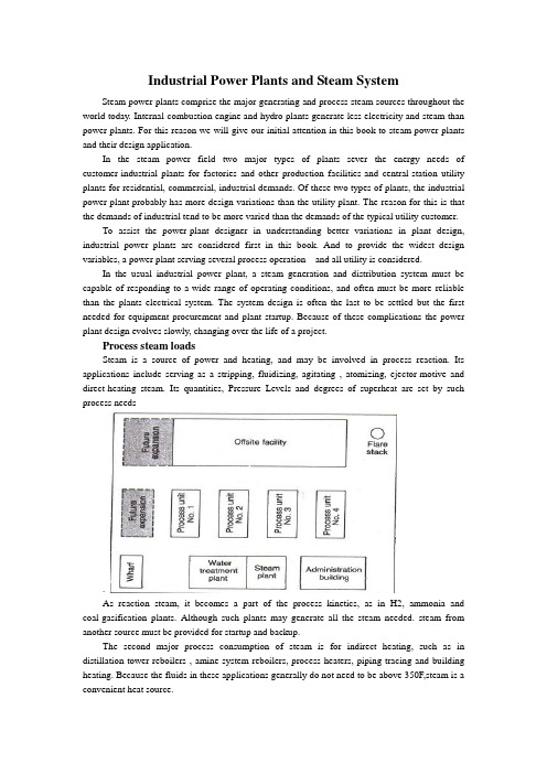
Industrial Power Plants and Steam SystemSteam power plants comprise the major generating and process steam sources throughout the world today. Internal-combustion engine and hydro plants generate less electricity and steam than power plants. For this reason we will give our initial attention in this book to steam power plants and their design application.In the steam power field two major types of plants sever the energy needs of customer-industrial plants for factories and other production facilities-and central-station utility plants for residential, commercial, industrial demands. Of these two types of plants, the industrial power plant probably has more design variations than the utility plant. The reason for this is that the demands of industrial tend to be more varied than the demands of the typical utility customer.To assist the power-plant designer in understanding better variations in plant design, industrial power plants are considered first in this book. And to provide the widest design variables, a power plant serving several process operation and all utility is considered.In the usual industrial power plant, a steam generation and distribution system must be capable of responding to a wide range of operating conditions, and often must be more reliable than the plants electrical system. The system design is often the last to be settled but the first needed for equipment procurement and plant startup. Because of these complications the power plant design evolves slowly, changing over the life of a project.Process steam loadsSteam is a source of power and heating, and may be involved in process reaction. Its applications include serving as a stripping, fluidizing, agitating , atomizing, ejector-motive and direct-heating steam. Its quantities, Pressure Levels and degrees of superheat are set by such process needs.As reaction steam, it becomes a part of the process kinetics, as in H2, ammonia and coal-gasification plants. Although such plants may generate all the steam needed. steam from another source must be provided for startup and backup.The second major process consumption of steam is for indirect heating, such as in distillation-tower reboilers , amine-system reboilers, process heaters, piping tracing and building heating. Because the fluids in these applications generally do not need to be above 350F,steam is a convenient heat source.Again, the quantities of steam required for the services are set by the process design of the facility. There are many options available to the process designer in supplying some of these low-level heat requirements, including heat-exchange system , and circulating heat-transfer-fluid systems, as well as system and electricity. The selection of an option is made early in the design stage and is based predominantly on economic trade-off studies.Generating steam from process heat affords a means of increasing the overall thermal efficiency of a plant. After providing for the recovery of all the heat possible via exchanges, the process designer may be able to reduce cooling requirements by making provisions for the generation of low-pressure(50-150 psig)steam. Although generation at this level may be feasible from a process-design standpoint, the impact of this on the overall steam balance must be considered, because low-pressure steam is excessive in most steam balances, and the generation of additional quantities may worsen the design. Decisions of this type call close coordination between the process and utility engineers.Steam is often generated in the convection section of fired process heaters in order to improve a plant’s thermal efficiency. High-pressure steam can be generated in the furnace convection section of process heater, which have radiant heat duty only.Adding a selective –catalytic-reduction unit for the purpose of lowing NOx emissions may require the generation of waste-heat steam to maintain correct operating temperature to the catalytic-reduction unit.Heat from the incineration of waste gases represents still another source of process steam. Waste-heat flues from the CO boilers of fluid-catalytic crackers and from fluid-coking units, for example, are hot enough to provide the highest pressure level in a steam system.Selecting pressure and temperature levelsThe selecting of pressure and temperature levels for a process steam system is based on:(1)moisture content in condensing-steam turbines,(2)metallurgy of the system,(3)turbine water rates,(4)process requirements ,(5)water treatment costs, and(6)type of distribution system.Moisture content in condensing-steam turbines---The selection of pressure and temperature levels normally starts with the premise that somewhere in the system there will be a condensing turbine. Consequently, the pressure and temperature of the steam must be selected so that its moisture content in the last row of turbine blades will be less than 10-13%. In high speed, a moisture content of 10%or less is desirable. This restriction is imposed in order to minimize erosion of blades by water particles. This, in turn, means that there will be a minimum superheat for a given pressure level, turbine efficiency and condenser pressure for which the system can be designed.System mentallurgy- A second pressure-temperature concern in selecting the appropriate steam levels is the limitation imposed by metallurgy. Carbon steel flanges, for example, are limited to a maximum temperature of 750F because of the threat of graphite (carbides) precipitating at grain boundaries. Hence, at 600 psig and less, carbon-steel piping is acceptable in steam distribution systems. Above 600 psig, alloy piping is required. In a 900- t0 1,500-psig steam system, the piping must be either a r/2 carbon-1/2 molybdenum or a l/2 chromium% molybdenum alloyTurbine water rates - Steam requirements for a turbine are expressed as water rate, i.e., lb of steam/bph, or lb of steam/kWh. Actual water rate is a function of two factors: theoretical water rate and turbine efficiency.The first is directly related to the energy difference between the inlet and outlet of a turbine, based on the isentropic expansion of the steam. It is, therefore, a function of the turbine inlet and outlet pressures and temperatures.The second is a function of size of the turbine and the steam pressure at the inlet, and of turbine operation (i.e., whether the turbine condenses steam, or exhausts some of it to an intermediate pressure level). From an energy stand point, the higher the pressure and temperature, the higher the overall cycle efficiency. _Process requirements - When steam levels are being established, consideration must be given to process requirements other than for turbine drivers. For example, steam for process heating will have to be at a high-enough pressure to prevent process fluids from leaking into the steam. Steam for pipe tracing must be at a certain minimum pressure so that low-pressure condensate can be recovered.Water treatment costs - The higher the steam pressure, the costlier the boiler feedwater treatment. Above 600 psig, the feedwater almost always must be demineralized; below 600 psig, soft,ening may be adequate. It may have to be of high quality if the steam is used in the process, such as in reactions over a catalyst bed (e.g., in hydrogen production).Type of distribution system - There are two types of systems: local, as exemplified by powerhouse distribution; and complex, by wluch steam is distributed to many units in a process plant. For a small local system, it is not impractical from a cost standpoint for steam pressures to be in the 600-1,500-psig range. For a large system, maintaining pressures within the 150-600-psig range is desirable because of the cost of meeting the alloy requirements for higher-pressure steam distribution system.Because of all these foregoing factors, the steam system in a chemical process complex or oil refinery frequently ends up as a three-level arrangement. The highest level, 600 psig, serves primarily as a source of power. The intermediate level, 150 psig, is ideally suitable for small emergency turbines, tracing off the plot, and process heating. The low level, normally 50 psig, can be used for heating services, tracing within the plot, and process requirements. A higher fourth level normally not justified, except in special cases as when alarge amount ofelectric power must be generated.Whether or not an extraction turbine will be included in the process will have a bearing on the intermediate-pressure level selected, because the extraction pressure should be less than 50% of the high-pressure level, to take into account the pressure drop through the throttle valve and the nozzles of the high-pressure section of' the turbine.Drivers for pumps and compressorsThe choice between a steam and an electric driver for a particular pump or compressor depends on a number of things, including the operational philosophy. In the event of a power failure, it must be possible to shut down a plant orderly and safely if normal operation cannot be continued. For an orderly and safe shutdown, certain services must be available during a power failure: (1) instrument air, (2) cooling water, (3) relief and blow down pump out systems, (4) boiler feedwater pumps, (5) boiler fans, (6) emergency power generators, and (7) fire water pumps.These services are normally supplied by steam or diesel drivers because a plant's steam or diesel emergency system is considered more reliable than an electrical tie-line.The procedure for shutting down process units must be analyzed for each type of processplant and specific design. In general, the following represent the minimum services for which spare pumps driven by steam must be provided: column reflux, bottoms and purge-oil circulation, and heater charging. Most important is to maintain cooling; next, to be able to safely pump the plant's inventory into tanks.Driver selection cannot be generalized; a plan and procedure must be developed for each process unit.The control required for a process is at times another consideration in the selection of a driver. For example, a compressor may be controlled via flow or suction pressure. The ability to vary driver speed, easily obtained with a steam turbine, may be basis for selecting a steam driver instead of a constant-speed induction electric motor. This is especially important when the molecular weight of the gas being compressed may vary, as in catalytic-cracking and catalytic-reforming processes.In certain types of plants, gas flow must be maintained to prevent uncontrollable high-temperature excursions during shutdown. For example, hydrocrackers are purged of heavy hydrocarbon with recycle gas to prevent the exothermic reactions from producing high bed temperatures. Steam-driven compressors can do this during a power failure.Each process operation must be analyzed from such a safety viewpoint when selecting drivers for critical equipment. The size of a relief and blowdown system can be reduced by installing steam drivers. In most cases, the size of such a system is based on a total power failure. If heat-removal powered by steam drivers, the relief system can be smaller. For example, a steam driver will maintain flow in the pump-around circuit for removing heat from a column during a power failure, reducing the relief load imposed on the flare system.Equipment support services (such as lubrication and sea-oil systems for compressors) that could be damaged during a loss of power should also be powered by steam drivers.Driver size can also be a factor. An induction electric motor requires large starting currents - typically six times the normal load. The drop in voltage caused by the startup of such a motor imposes a heavy transient demand on the electrical distribution system. For this reason, drivers larger than 10,000 hp are normally steam turbines, although synchronous motors as large as 25,000 hp are used.The reliability of life-support facilities - e.g., building heat, potable water, pipe tracing, emergency lighting-during power failures is of particular concern mates. In such a case, at least one boiler should be equipped with steam-driven auxiliaries to provide these services.Lastly, steam drivers are also selected for the purpose of balancing steam systems and avoiding large amounts of letdown between steam levels. Such decisions regarding drivers are made after the steam balances have been refined and the distribution system has been fully defined. There must be sufficient flexibility to allow balancing the steam system under all operating conditions.Selecting steam driversAfter the number of steam drivers and their services have been established, the utility, or process engineer will estimate the steam consumption for making the steam balance.The standard method of doing this is to use the isentropic expansion of steam correeted for turbine efficiency.Actual steam consumption by a turbine is determined via:SR = (TSR)(bhp)/EHere, SR = actual steam rate, lb/h; TSR = theoretical steam rate, lb/hr/bhp ; bhp = turbine brake horsepower; and E = turbine efficiency.When exhaust steam can be used for process heating, the highest thermodynamic efficiency can be achieved by means of backpressure turbines. Large drivers, which are of high efficiency and require low theoretical steam rates, are normally supplied by the high-pressure header, thus minimizing steam consumption.Small turbines that operate only in emergencies can be allowed to exhaust to atmosphere. Although their water rates are poor, the water lost in short-duration operations may not represent a significant cost. Such turbines obviously play a small role in steam balance planning.Constructing steam balancesAfter the process and steam-turbine demands have been established, the next step is to construct a steam balance for the chemical complex or oil refinery. A sample balance is shown in Fig. 1-4. It shows steam production and consumption, the header systems, letdown stations, and boiler plant. It illustrates a normal (winter) case.It should be emphasized that there is not one balance but a series, representing a variety of operating modes. The object of the balances is to determine the design basis for establishing boiler she, letdown stations and deaerator capacities, boiler feedwater requirements, and steam flows in various parts of the system.The steam balance should cover the following operating modes: normal, all units operating; winter and summer conditions; shutdown of major units; startup of major units; loss of largest condensate source; power failure with flare in service; loss of large process steam generators; and variations in consumption by large steam users.From 50 t0 100 steam balances could be required to adequately cover all the major impacts on the steam system of a large complex.At this point, the general basis of the steam system design should have been developed by the completion of the following work:1. All significant loads have been examined, with particular attention focused on those for which there is relatively little design freedom - i.e., reboilers, sparing steam for process units, large turbines required because of electric power limitation and for shutdown safety.2. Loads have been listed for which the designer has some liberty in selecting drivers. These selections are based on analyses of cost competitiveness.3. Steam pressure and temperature levels have been established.4. The site plan has been reviewed to ascertain where it is not feasible to deliver steam or recover condensate, because piping costs would be excessive.5. Data on the process units are collected according to the pressure level and use of steam - i.e., for the process, condensing drivers and backpressure drivers.6. After Step 5, the system is balanced by trial-and-error calculations or computerized techniques to determine boiler, letdown, deaerator and boiler feedwater requirements.7. Because the possibility of an electric power failure normally imposes one of the major steam requirements, normal operation and the eventuality of such a failure must both be investigated, as a minimum.Checking the design basisAfter the foregoing steps have been completed, the following should be checked:Boiler capacity - Installed boiler capacity would be the maximum calculated (with an allowance of l0-20% for uncertainties in the balance), corrected for the number of boilers operating (and on standby).The balance plays a major role in establishing normal-case boiler specifications, both number and size. Maximum firing typically is based on the emergency case. Normal firing typically establishes the number of boilers required, because each boiler will have to be shut down once a year for the code-required drum inspection. Full-firing levels of the remaining boilers will be set by the normal steam demand. The number of units required (e.g., three 50% units, four 33%units, etc.) in establishing installed boiler capacity is determined from cost studies. It is generally considered double-jeopardy design to assume that a boiler will be out of service during a power failure.Minimum boiler turndown - Most fuel-fired boilers can be operated down to approximately 20% of the maximum continuous rate. The maximum load should not be expected to be below this level.Differences between normal and maximum loads –If the maximum load results from an emergency (such as power failure), consideration should be given to shedding process steam loads under this condition in order to minimize in- stalled boiler capacity. However, the consequences of shedding should be investigated by the process designer and the operating engineers to ensure the safe operation of the entire process.Low-level steam consumption - The key to any steam balance is the disposition of low-level steam. Surplus low-level steam can be reduced only by including more condensing steam turbines in the system, or devising more process applications for it, such as absorption refrigeration for cooling process streams and ranking-cycle systems for generating power. In general, balancing the supply and consumption of low-level steam is a critical factor in the design of the steam system.Quantity of steam at pressure-reducing stations - Because useful work is not recovered from the steam passing through a pressure-reducing station, such flow should be kept at a minimum. In the Fig. 1-5 150/50-psig station, a flow of only 35,000 lb/h was established as normal for this steam balance case (normal, winter). The loss of steam users on the 50-psig systems should be considered, particularly of the large users, because a shutdown of one may demand that the 150/50-psig station close off beyond its controllable limit. If this happened, the 50-psig header would be out of control, and an immediate-pressure buildup in the header wouldbegin, setting off the safety relief valves.The station's full-open capacity should also be checked to ensure that it can make up any 50-psig steam that may be lost through the shutdown of a single large 50-psig source (a turbine sparing a large electric motor, for example}. It would be undesirable for the station to be sized so that it opens more than 80%. In some cases, range ability requirements may dictate two valves (one small and one large).Intermediate pressure level - If large steam users or suppliers may come on stream or go off steam, the normal(day-to-day) operation should be checked. No such change in normal operation should result in a significant upset (e.g.,relief valves set off, or the system pressure control lost).If a large load is lost, the steam supply should be reduced by the letdown-station. If the load suddenly increases, the 600/150-psig station must be able of supplying the additional steam. If steam generated via the process disappears, the station must be capable of making up theload. If150-psig steam is generated unexpectedly, the 600/150-psig station must be able to handle the cutback.The important point here is that where the steam flow could rise t0 700,000 lb/h, this flow should be reduced by a cutback at the 600/150-psig station, not by an increase in the flow to the lower-pressure level, because this steam would have nowhere to go. The normal (600/150-psig) letdown station must be capable of handling some of the negative load swings, even though, overall, this letdown needs to be kept to a minimum.On the other hand, shortages of steam at the 150-psig level can be made up relatively easily via the 600/150-psig station. Such shortages are routinely small in quantity or duration, or both-(startup, purging, electric drive maintenance, process unit shutdown, etc.)High-pressure level - Checking the high-pressure level is generally more straightforward because rate control takes place directly at the boilers. Firing can be increased or lowered to accommodate a shortage or surplus.Typical steam-balance casesThe Fig. 1-4 steam balance represents steady-state condition, winter operation, all process units operating, and no significant unusual demands for steam.An analysis similar to the foregoing might also be required for the normal summertime case, in which a single upset must not jeopardize control but the load may be less (no tank heating, pipe tracing, etc.)The balance representing an emergency (e.g., loss of electric power) is significant. In this case, the pertinent test point is the system's ability to simply weather the upset, not to maintain normal, stable operation. The maximum relief pressure that would develop in any of the headers represents the basis for sizing relief valves. The loss of boiler feed water or condensate return, or both, could result in a major upset, or even a shutdown.Header pressure control during upsetsAt the steady-state conditions associated with the multiplicity of balances, boiler capacity can be adjusted to meet user demands. However, boiler load cannot be changed quickly to accommodate a sharp upset. Response rate is typically limited to 20% of capacity per minute. Therefore, other elements must be relied on to control header pressures during transient conditions.The roles of several such elements in controlling pressures in the three main headers during transient conditions are listed in Table l-3. A control system having these elements will result in a steam system capable of dealing with the transient conditions experienced in moving from one balance point to another.Tracking steam balancesBecause of schedule constraints, steam balances and boiler size are normally established early in the design stage. These determinations are based on assumptions regarding turbine efficiencies, process steam generated in waste-heat furnaces, and other quantities of steam that depend on purchased equipment. Therefore, a sufficient number of steam balances should be tracked through the design period to ensure that the equipment purchased will satisfy the original design concept of the steam system.This tracking represents an excellent application for a utility data-base system and a system linear programming model. During the course of the mechanical design of a large "grass roots" complex, 40 steam balances were continuously updated for changes in steam loads via such an application.Cost tradeoffsTo design an efficient but least-expensive system, the designer ideally develops a total minimum-cost curve – which incorporates all the pertinent costs related to capital expenditures, installation, fuel, utilities, operations and maintenance-and performs a cost study of the final system. However, because the designer is under the constraint of keeping to a project schedule, major, highly expensive equipment must be ordered early in the project, when many key parts of the design puzzle are not available (e.g., a complete load summary, turbine water rates, equipment efficiencies and utility costs).A practical alternative is to rely on comparative-cost estimates, as are conventionally used in assisting with engineering decision points. This approach is particularly useful in making early equipment selections when fine-tuning is not likely to alter decisions, such as regarding the number of boilers required, whether boilers should be shop-fabricated or field-erected, and the practicality of generating steam from waste heat or via cogeneration.The significant elements of a steam-system cost-comparative study are costs for: equipment and installation; ancillaries (i.e., miscellaneous items required to support the equipment,such as additional stacks, upgraded combustion control, more extensive blowdown facilities, etc.); operation(annual); maintenance (annual); and utilities.The first two costs may be obtained from in-house data or from vendors. Operational and maintenance costs can be factored from the capital cost for equipment based on an assessment of the reliability of the purchased equipment.Utility costs are generally the most difficult to establish at an early stage because sources frequently depend on the site of the plant. Some examples of such costs are: purchased fuel gas - $5.35/million Btu, raw water - $0.60/1,000 gal, electricity - $0.07{kWh, and demineralized boiler feedwater -$1.50/1,000 gal. The value of steam at the various pressureLevels can be developed [5J.Let it be further assumed that the emergency balance requires 2,200,000 lb/h of steam (all boilers available). Listed in Table 1 4 are some combinations of boiler installations that meet the design conditions previously stipulated.Table l-4 indicates that any of the several combinations of power-boiler number and size could meet both normal and emergency demand. Therefore, a comparative-cost analysis would be made to assist in making an early decision regarding the number and size of the power boilers.(Table l-4 is based on field-erected, industrial-type boiler Conventional sizing of this type of boiler might range from 100,000 lb/h through 2,000,000 lb/h for each.)An alternative would be the packaged boiler option (although it does not seem practical at this load level. Because it is shop-fabricated, this type of boiler affords a significant saving in terms of field installation cost. Such boilers are available up to a nominal capacity of 100,000 lb/h, with some versions up t0 250,000 lb7h.Selecting turbine water rate i.e., efficiency) represents another major cost concern. Beyond the recognized payout period (e.g., 3 years), the cost of drive steam can be significant in comparison with the equipment capital cost. The typical 30% efficiency ofthe medium-pressure backpressure turbine can be boosted significantly.Driver selections are frequently made with the help of cost-tradeoff studies, unless overriding considerations preclude a drive medium. Electric pump drives are typically recommended on the basis of such studies.Steam tracing has long been the standard way of winterizing piping, not only because of its history of successful performance but also because it is an efficient way to use low-pressure steam.Design consideratonsAs the steam system evolves, the designer identifies steam loads and pressure levels, locates steam loads, checks safety aspects, and prepares cost-tradeoff studies, in order to provide low-cost energy safely, always remaining aware of the physical entity that will arise from the design.How are design concepts translated into a design document? And what basic guidelines will ensure that the physical plant will represent what was intended conceptually?Basic to achieving these ends is the piping and instrument diagram (familiar as the P&ID). Although it is drawn up primarily for the piping designers benefit, it also plays a major role in communicating to the instrumentation designer the process-control strategy, as well as in conveying specialty information to electrical, civil, structural, mechanical and architectural engineers. It is the most important document for representing the specification of the steam。
- 1、下载文档前请自行甄别文档内容的完整性,平台不提供额外的编辑、内容补充、找答案等附加服务。
- 2、"仅部分预览"的文档,不可在线预览部分如存在完整性等问题,可反馈申请退款(可完整预览的文档不适用该条件!)。
- 3、如文档侵犯您的权益,请联系客服反馈,我们会尽快为您处理(人工客服工作时间:9:00-18:30)。
毕业论文(设计)——外文翻译(2006 届本科)题目: 某小区住宅楼施工组织设计学院:水利学院专业:土木工程姓名:闫象庆指导教师:李玉清副教授完成日期: 2006 年 3 月 15 日施工进度计划中施工段排序优化的概念分析及施工组织设计的改进摘要:施工组织设计作为指导施工全过程各项活动的技术经济的纲领性文件,是施工技术与施工项目管理有机结合的产物,它是工程开工后施工活动能有序、高效、科学合理地进行的保证。
随着我国经济的快速发展及市场经济的逐步完善,建筑施工企业普遍面临者市场广阔、利润率低、技术难度加大的现状。
因此,如何科学地进行施工组织、降低工程施工成本,成为施工企业应着重考虑的问题之一。
本文作者在查阅了大量资料的基础上,首先对施工进度计划的原理、任务和作用,流水施工原理、组织方法,网络计划技术及其优化进行了系统的归纳和阐述,然后主要对施工段排序优化进行了深入研究,根据作者多年的工程管理实践,从基本概念入手,提出了利用概念分析法进行施工段排序优化的新方法,列出了优化步骤,并且利用VC语言编制了程序来实现施工段排序优化。
最后结合两个工程实例,从工程实践角度,证实了该方法的正确性及有效性。
并着重指出,该方法不仅可以缩短工期,同时也可以降低施工成本,而且比较适合广大施工企业工程管理人员的实际水平。
关键词:施工进度计划;流水施工;概念分析法;网络计划技术。
随着社会经济的发展和建筑技术的进步,现代建筑施工过程已成为一项十分复杂的生产活动。
一个大型建设项目的建筑施工安装工作,不但包括组织成千上万的各种专业建筑工人和数量众多的各类建筑机设备有条不紊地投入工程施工中,而且还包括组织种类繁多的,数以几十甚至几百万吨计的建筑材料、制品和构配件的生产、运输、贮存和供应工作,组织施工机具的供应、维修和保养工作,组织施工现场临时供水、供电、供热以及安排施工现场的生产和生活所需要的各种临时建筑物等工作。
这些工作的组织与协调,对于多快好省地进行工程建设具有十分重要的意义。
建筑施工组织的任务就是针对工程施工的复杂性,来研究工程建设的统筹安排与系统管理的客观规律,研究如何组织计划一项拟建工程的全部施工,寻求最合理的组织方法,实现工程建设计划和设计的要求,提供各阶段的施工准备工作内容,对人力、资金、材料、机械和施工方法等进行科学合理的安排,协调施工中各施工单位、各工种之间、资源与时间之间、各项资源之间的合理关系。
在整个施工过程中,按照客观的技术经济规律,做出科学合理的安排,以使工程施工取得相对最优的效果。
但是,从施工组织设计编制的特点看:施工组织设计是以单个工程为对象进行编制的,有很强的技术性和综合性,需要编制人员有足够的建筑工程理论基础和一定的实践经验。
施工组织设计的内容必须适应工程项目和业主、设计、监理的特殊要求,同时也必须符合国家有关法律、法规、标准及地方规范的要求。
施工组织设计编制必须满足最终的一个基本要求即对施工过程起到指导和控制作用,在一定的资源条件下实现工程项目的技术经济效益,达到施工效益与经济效益双赢的目的。
施工组织设计编制目前所存在的缺陷:1.目前所累积的施工技术资源得不到有效、充分的应用,特别是其中的智力资源,这一方面是编制人员自身素质和经验不足造成的;另一方面是传播渠道不足不畅通所致。
对早已有的成功经验没有进行借鉴,所编制的内容缺乏新技术、新工艺,没有起到提高劳动效率、降低资源消耗的作用。
2.有的施工组织设计编制人员缺乏技术理论基础和具体施工经验,编制中只是对技术规范照搬照抄,而未对具体工程的特点进行有针对性的规划和设计,没有起到指导施工作用。
3.施工组织设计必须对每个工程逐个进行编制,以适应不同工程的特点,但不同编制人员对于同类型的施工工艺在进行编制工作的同时,作了大量不必要的重复劳动,降低了工作效率。
4.现在编制的施工组织设计只作为技术管理制度的一项工作,它主要追求施工效益而很少考虑经济效益,存在只注重组织技术措施,而没注重经济管理的内容,以至在实施过程中不讲成本,没有实现经济效益的目标。
5.目前施工组织设计的编制经常是设计与实施分离,以至造成施工组织设计只是个形式而已,不能真正起到指导施工的作用。
组织管理者必须充分认识施工过程的特点,对所有环节要做到精心组织、严格管理、全面协调好施工中的各种关系。
对于特殊复杂的施工过程,要进行科学的分析,弄清主次矛盾,找出关键线路,有的放矢措施,合理组织各种资源的投入顺序、数量、比例,进行科学的工程排队,组织平行交叉流水作业,提高对时间、空间的利用,这样才能取得全面的经济效益和社会效益。
因此,随着科学技术的发展和建筑水平的不断提高,管理体制的进一步完善,原有的传统施工组织设计编制方法已不能适应现在的要求。
目前我国已加入了WTO,为了适应日益激烈的市场竞争形势,适应建筑市场和新型施工管理体制的需要,要具备建造现代化建筑物的技术力量和手段,就必须对现在的施工组织设计的编制方法进行改进。
实施办法如下:1.运用系统的观念和方法,建立施工组织设计编制工作的标准。
工程管理部门对建筑工程的大中型项目施工组织设计进行收集,经过分析和归纳,整理并发布,则能使先进的施工组织设计更能发挥效益,减少编制人员重复劳动,而且能推广先进经验。
2.施工组织设计的内容就是根据不同工程的特点和要求,根据现有的和可能创造的施工条件,从事实出发,决定各种生产要素的结合方式。
选择合理的施工方案是施工组织设计的核心,应根据多年积累的施工技术资源,同时借鉴国内外先进施工技术,运用现代科学管理方法并结合工程项目的特殊性,从技术及经济上互相比较,从中选出最合理的方案来编制施工组织设计,使技术上的可行性同经济上的合理性统一起来。
3.施工组织设计内容应简明扼要,突出目标,结合实际、满足招标文件的需要,要具有竞争性,能体现企业的实力和信誉。
4.实行施工组织设计的模块化编制,更多的运用现代化信息技术,以便进行积累、分组、交流及重复应用,通过各个技术模块的优化组合,减少无效劳动。
5.努力贯彻国家质量管理体系标准,走质量效益型发展道路,建立并完善科学的、规范的质量管理体系。
逐项地编制质量保证计划,与施工组织设计工作同时进行,并努力使二者有机结合起来。
6.施工组织设计应扩大深度和范围,对设计图纸的合理性和经济性做出评估,实现设计和施工技术的一体化,扩大技术积累,加快技术转化,使新的技术成果在施工组织设计中得到应用。
在知识经济时代,信息技术在工程项目中已起到越来越大的作用,应大力发展和运用信息技术,重视高新技术的移植和利用,拓宽智力资源的传播渠道,全面改进传统的编制方法,使信息在生产力诸要素中起到核心的作用,逐步实现施工信息自动化、施工作业机器化、施工技术模块化和系统化,以产生更大的经济效益,增强竞争力,在日益激烈的竞争中获得更好的生存环境。
而现阶段建筑施工组织研究发展的特点是广泛应用数学方法,网络技术和计算技术等定量性方法,应用现代化的计算手段—电子计算机,采用各种有效手段,对整个工程的施工进行工期、成本、质量的控制,达到工期短、质量好和成本低的目的。
施工进度计划利用网络图的方式表达后,可以通过数学推导形成算法或逻辑过程,并利用数值计算迭代,即可直接求得最优方案。
施工网络优化不仅能大大节省工作时间,增进决策的科学性,而且能产生巨大的经济效益。
但是,由于施工进度计划的编制过程中将施工对象划分成若干个施工段,则施工队进入不同施工段的顺序不同,施工计划的工期也不同。
要在资源固定,保证施工工艺顺序不变的前提下,合理安排施工进度计划的工程排序,缩短工期,则需对不同施工段的施工顺序做出多方案的组合,从中得出最优施工顺序的方案。
In the construction progress plan executes the concept analytic method and the construction organization plan, which the construction section arrangement optimizesAbstractThe construction organization plan constructs the entire process each activity technical economy Platform as the instruction, is constructs technical and the construction project management organic synthesis product, after it is the project begins to construct the activity to be able to .。
As the development of our country's economy and the consummating of market-economy system gradually. Many constructioncorporations are facing the much opportunity, but at the same time, they are facing much difficulty, such as profit-ratio dropping, , the effect and principle of low-construction and illuminating the means of making the construction-plan more preferential. The author also researching the superiority way of construction-sequence deeply, based on years' experience in construction management , computer inC .Finally its effect. They manifest that the means dose not only shorten the period, but also decrease the cost of construction. I argue that the superiority-means about construction practically accommodate the most of construction enterprise.Keyword:Construction process plan; Concept analy siswayConstruction unit superiority ; Net plan technique Along with the social economy development and the construction technology progress, the modern architecture construction process extremely complex production activity. A large-scale items of basic construction work, not only includes organizes thousands of each kinds of specialized construction worker and the quantity multitudinous, and each kind of building machine equipment methodically invests in the project construction, moreover also includes the organization type so many to several dozens even several million tons of building materials, products, constructs and their production, transportation, storing and supply work, also the organization construction machines and tools supply, the service and the maintenance, work and so on , each kind of temporary building which the organization job location temporary water supply, the power supply, production and the life needs. These work organizations and the coordination regard economically carrying on the engineering construction organization's duty is againsting the project construction's complexity, studying the engineering construction theoverall plan arrangement and the system administration objective law, to plan method, and the realization engineering construction plans the request which and designs, provides various stages the construction preparatory work content, to the manpower, the fund, the material, the machinery and the job practice and so on carries on the science reasonable arrangement, in the coordinated construction between each construction, various kinds of work in a factory, the resources and the time, each item of resources reasonable relations. In the entire construction process, according to the objective technology economic law, makes the science reasonable arrangement, by causes the project construction to obtain the relative most superior effect.Looked from the construction organization plan establishment characteristic that, The construction organization plan is carries on the establishment take the single project as the object, experience. The construction organization plan content must adapt the engineering project and the owner, the design, the overseeing special request, at the same time also must conform to the national relevant law, the laws and regulations, the standard and the place standard request. The construction organization plan establishment must satisfy a final basic request namely to get up to the construction process to the instruction and the control action, realizes the engineering project technology economic efficiency under the certain resources condition, achieved the construction benefit and the economic efficiency double win goal.The construction organization plan establishment exists at present flaw:1. at present accumulates the construction technological resource cannot obtain, the full application effectively, especially intelligence resources, this on the one quality and is insufficiently experienced creates; On the other the model, establishes the content lacks the newtechnology, the new craft, to the enhancement labor efficiency, reduces the resources consumption the function.2.Some construction organization plan establishments of strength lack of the technology rationale and the concrete construction experience, in the establishment only are imitate to the technology standard copy verbatim, but to the concrete project characteristic and the design, does not construction function.3.The construction organization plan must carry on the establishment to each project one by one, by adapts the different project characteristic, but the different establishment of strength while carries on the establishment work regarding the similar construction craft, organization plan only took the technical management system a work, it mainly pursues the construction benefit but very little to consider the economic efficiency, the existence only pays great attention to the organization technology measure, but to the economical management the content, down to does not speak the cost in the implementation process, organization plan establishment is frequently the design and the implementation separates, down to create the construction organization plan only is a form, cannot be true to the instruction construction function.Organizes the superintendent to process the characteristic, must achieve the careful organization, the strict management to all links, and comprehensively coordinates in the good construction each kind of relations. Regarding the special complex construction process, must carry on the science the analysis, clarifies the primary and secondary contradiction, discovers the essential line, the measure, reasonably organizes each kind of resources with a clear goal the investment order, the quantity, the proportion, carries on the science the project to line up, the organization parallel overlapping streamlined production, enhancesto the time, the spatial use, like this can obtain the comprehensive economic efficiency and the social efficiency.Along with the science and technology development and the construction level unceasing enhancement, manages the system the further consummation, the original tradition construction organization plan establishment method able to adept the present request. At present our country order to adapt day by day the intense market competition situation, the adaption construction market and the new construct control system need, must modernization building technical force and the method, must make the improvement to the present construction organization plan establishment method. Implementation means as follows:1. using the system idea and the method, establish the construction organization plan establishment works the standard. The project management department carries on the collection to the architectural engineering large and middle scale projects construction organization plan, the process analysis and the induction, the reorganization and the issue, then can enable the advanced construction organization plan to display the benefit, reduces the establishment of strength to duplicate works, moreover can promote the advanced experience.2. The construction organization plan content is according to the different project characteristic and the request, according to construction condition which existing and possibly creates, embarks from the fact, decides each kind of element of production the union way. Chooses the reasonable construction plan is the construction organization plan core, should act according to many years accumulation the construction technological resource, at the same time profits from the domestic and foreign advanced constructions technology, the utilization modern scientific management method and the union engineering projectparticularity, from technology and economy mutual comparison, selects the most reasonable plan to establish the construction organization plan, causes in technical in the feasible same economy rationality to unify.3. The construction organization plan content should be brief and to the point, the prominent goal, the union is actual, satisfies the tender document the need, must manifest the enterprise the strength and the prestige.4.Implementation construction organization plan modular establishment, more utilization modernization information technology, in order to carries on the accumulation, the grouping, the exchange and the repetition application, through each technical module optimum composition, reduces the invalid work.5. Implements the country quality control system standard diligently, walks the quality efficiency development path, the establishment and the consummation science, the standard quality control system. Establishes the quality guarantee plan item by item, carries on with the construction organization plan work also, and causes the two organic syntheses diligently.6. The construction organization plan should expand the depth and the scope, makes the appraisal to the design paper rationality and the efficiency, the realization designs and constructs the technical integration, the expanded technology accumulates, speeds up the technology to transform, enable the new technical achievement to obtain the application in the construction organization plan.In the knowledge economy time, the information technology in the engineering project to the more and more major function, should develop and the utilization information technology vigorously, takes the channel, comprehensively improves traditional the establishment method, causes the information in the productive forces various essential factors to thecore function, realizes the construction information automation, construction work , the construction technology modulation and the systematization gradually, by keen competition.The present stage construction organization studies the development the characteristic is the widespread applied mathematics method, network technology and computation technology and so on the method, the application modernization computation method electronic accounting machine, uses each effective method, carries on the time limit for a project, the cost, the quality control to the entire project construction, achieved the time limit for a project short, the quality is good and the cost low goal.After the construction progress plan use network chart way expression, may form the algorithm or the logical process through mathematics inferential reasoning, and using the value computation iteration, then directly obtains the most superior plan. The construction network optimizes not only can save the operating time operating time greatly, promotes policy-making the scientific nature, moreover can the construction progress plan establishment process will construct the object to divide certain to execute the construction section, then will execute the engineering unit to enter differently executes the construction section the order differently, the construction plan time limit for a project will be also different. Must be fixed in the resources, guaranteed under the construction craft order invariable premise, reasonably arranges the construction progress plan the project arrangement, reduces the time limit for a project, then must to differently execute the construction section the construction order to make the multi- plans the combination, obtains the most superior construction order the plan.。