1 LTE综述
LTE系统概述范文

LTE系统概述范文LTE(Long Term Evolution)是一种第四代(4G)无线通信技术,是继2G(GSM)和3G(UMTS)之后的下一代移动通信技术。
它旨在提供更高的数据传输速度、更低的时延和更好的覆盖范围,以满足日益增长的移动宽带需求。
LTE系统的核心是基于IP的无线通信网络,它采用了分组交换的技术,与传统的电路交换网络相比,能够更高效地利用网络资源。
在LTE系统中,无线电接入网络(Radio Access Network,RAN)负责无线信号的传输和接收,核心网络(Core Network)则负责数据传输、处理和路由等功能。
2.低时延:由于LTE系统采用了分组交换的技术和优化的协议,使得无线网络的时延相对较低。
这对于实时应用(如在线游戏、视频通话)和位置服务非常重要,能够提供更好的用户体验。
3. 高容量:LTE系统的无线接口采用了OFDMA(Orthogonal Frequency Division Multiple Access)技术,这是一种多用户接入技术,能够将频谱资源划分给多个用户同时使用,从而提高网络的容量和可伸缩性。
4.灵活的频谱分配:LTE系统可以灵活地分配频谱资源,支持不同频带(如700MHz、1800MHz、2.6GHz等)的使用,以满足不同运营商和地区的需求。
5.广泛的覆盖范围:LTE系统的网络规划和无线传输技术使得其覆盖范围更广,能够实现更好的室内和室外覆盖,为用户提供更稳定的信号质量。
6.兼容性:LTE系统具有对已有的2G和3G网络的兼容性。
它可以与GSM和UMTS网络进行互操作,这意味着运营商可以逐步升级其现有的网络到LTE系统,而无需进行全面的替换。
7.低能耗:LTE系统采用了一些节能技术,如功率控制和休眠模式等,使得设备在使用无线网络时能够更有效地利用电池能量,延长设备的使用时间。
总之,LTE系统作为一种高速、低时延、高容量和兼容性强的无线通信技术,已经在全球范围内得到广泛应用。
lte技术
lte技术第一篇:LTE技术原理和特点1.1 LTE技术原理LTE(Long-Term Evolution)是一种基于OFDM (Orthogonal Frequency Division Multiplexing)的4G无线通信技术。
它主要是通过频分复用将频域分成若干个子载波,每个子载波可以传输一个数据流,同时在时域上通过多路复用技术实现多个用户的数据传输。
由于OFDM技术的高效率和误码率的低值,使得LTE具有更好的覆盖范围和抗干扰能力,不断有新的技术被应用到LTE中,比如MIMO(Multiple-input and multiple-output)、VoLTE(Voice over LTE)和Carrier Aggregation(CA)等,不断提升着LTE技术的性能。
1.2 LTE技术特点(1)更高的数据速率,更低的时延。
由于LTE技术利用的是OFDM技术,在广阔的频带内分成很多的子载波,实现的是并行传输,可以提高数据速率,一般可以达到100Mbps的下行速率和50Mbps的上行速率,时延也可以控制在10ms以下。
(2)更好的数据覆盖和信号质量。
由于LTE技术的高效率和误码率的低值,使得其具有更好的覆盖范围和抗干扰能力,而且还可以通过一些技术手段例如VoLTE来提高语音通话的质量。
(3)更丰富的业务应用。
LTE技术可以支持更丰富的业务应用,不仅包括传统的语音通信和数据传输,还包括一些新型的业务应用,例如高清视频传输、IoT(物联网)等,可以为用户提供更好的服务体验。
(4)更灵活的网络组网方式。
由于LTE技术使用的网络协议灵活多变,网络组网方式也更加灵活,可以实现单网、多层次、多种技术的混合组网模式,更加方便网络管理和维护。
(5)更加低成本的部署和维护。
LTE的部署和维护成本较低,因为采用的是基于IP的全网络架构,使得网络的部署和维护工作更加简单,而且维护人员的培训成本也较低。
1.3 总结LTE技术采用OFDM技术,实现了更高的数据速率、更好的数据覆盖和信号质量、更丰富的业务应用、更灵活的网络组网方式和更加低成本的部署和维护,这些都是构成LTE技术的重要特点。
LTE介绍与网络架构
LTE介绍与网络架构LTE(Long-Term Evolution),即长期演进技术,是第四代移动通信标准。
它是3GPP(Third Generation Partnership Project)组织制定的全球统一标准,旨在提供更高的数据传输速率、更低的延迟和更高的系统容量,以满足不断增长的移动通信需求。
LTE网络架构主要由以下几个部分组成:用户终端(UE)、基站子系统(eNB)、核心网络(Core Network)和运营商网络。
首先是用户终端,即智能手机、平板电脑或其他支持LTE技术的设备。
用户终端与LTE网络进行通信,发送和接收数据。
其次是基站子系统(eNB),它由一台或多台基站控制器和一组基站天线组成。
基站子系统用于与用户终端进行通信,传输数据和控制信号。
核心网络是网络的核心部分,它提供网络管理和控制功能。
核心网络包括多个网络元素,如移动交换中心(MSC)和数据网关(SGW)。
移动交换中心负责处理语音通信,数据网关则负责处理数据传输。
运营商网络是LTE网络的运营者,它由多个基站子系统和核心网络组成。
运营商网络提供网络覆盖和服务,并负责管理用户终端的接入和连接。
LTE网络架构中的一个重要概念是分组交换。
与之前的电路交换网络不同,LTE网络采用了分组交换技术,将数据分成小的数据包进行传输。
这种架构有助于提高数据传输速率和系统容量,并降低网络延迟。
在LTE网络中,数据传输的基本单位是无线帧(Radio Frame)。
每个无线帧由多个子帧(Subframe)组成,每个子帧由多个时隙(TimeSlot)组成。
时隙是最小的单位,用于传输数据和控制信号。
在每个时隙中,数据和控制信号可以同时传输,从而实现高效的通信。
此外,LTE网络采用了多天线技术,即MIMO(Multiple-Input-Multiple-Output)。
MIMO技术使用多个天线进行数据传输和接收,可以提高系统容量和数据传输速率,并改善网络覆盖范围。
1_LTE综述
EPC
S6d S6a S11 S4 S5/S8 HSS PCRF Gx PDN GW SGi S9
UMTS NodeB
RNC
MME
Operator Service Network
S12 S1-MME S1-U E-UTRAN eNodeB BSC cdma2000 BTS A10/A11 PDSN S2a Corporate Internet Serving GW Internet
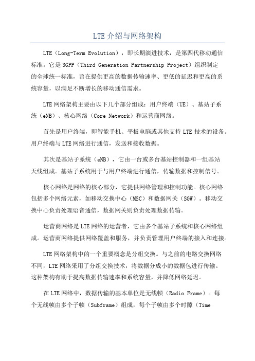
EPC主要有三部分: MME(Mobility Management Entity:负责信令处理部分) S-GW(Serving Gateway:负责本地网络用户数据处理部 分) P-GW(PDN Gateway:负责用户数据包与其他网络的处理) 接入网由eNodeB构成 网络接口 S1接口:eNodeB与EPC X2接口:eNodeB之间 Uu接口:eNodeB与UE
1Mbps
ADSL 256Kbps Analog 56Kbps
100ms 50ms 15ms 2015
Analog
28.8Kbps
<1990
1995
2000
2002
2005
2007
2009
2011
移动用户享有固网用户同等的业务感受
6
LTE的新业务
业务类型 SMS MMS Web 浏览 Email GPRS/EDGE ● ● ● ● UMTS ● ● ● ● LTE ● ● ● ●
DL:46.5Mbps UL:27Mbps
13
LTE主要设计目标
峰值速率: 下行峰值100Mbps,上行峰值50Mbps 时延: 控制面 IDLE→ACTIVE:< 100ms 用户面的单向传输:< 5ms 移动性:350km/h(在某些频段甚至支持500km/h) 频谱灵活性: 带宽从1.4MHz~20MHz(1.4、3、5、10、15、20)
LTE功率控制综述综述

2019扰协调 小区专属天线端口下的ρ A/ρ B比。其由高层信令 通知的小区专用参数 以及 eNodeB 配置的小区专用 天线端口数目决定。
小区专属天线端口下的ρ A/ρ B比
2019/2/20
2019/2/20
7
用户功率分配和小区间干扰协调
小区专属比值与PDSCH使用的不同传输模式有关。对于16QAM、 64QAM调制、多层空分复用,或多用户MIMO的PDSCH传输: ������ 当UE接收使用4小区特定天线端口发送分集预编码传输的PDSCH数 据时:ρ A= power -offset PA 10log10 (2) 其他情况下:ρ A= power -offset PA 其中,在除了多用户MIMO之外的所有传输模式中, power -offset 均为0; 在指示 B / A基础上,通过高层参数 PA 确定 ρ A的具体数值,得到 基站下行针对用户的PDSCH发射功率。
下行功率分配
在频率和时间上采用恒定的发射功率,基站通过高 层信令指示该发射功率数值。 在LTE系统中,使用每资源单元容量(Transmit Energy per Resource Element, EPRE)来衡量下行 发射功率大小。 下行功率分配方法: 提高参考信号的发射功率(Power Boosting) 与用户调度相结合实现小区间干扰抑制的相关 机制
2019/2/20
5
提高参考信号的发射功率-Power Boosting
ρ A或 ρ B表示每个OFDM符号内的PDSCH EPRE和小区专属RS EPRE的比 值,且ρ A或ρ B是UE专属的。 在包含RS的数据OFDMA的EPRE与小区专属RS EPRE的比值标识用ρ B
表示; 在不包含RS的数据OFDMA的EPRE与小区专属RS EPRE的比值标识用 ρ A表示。
1 LTE 技术概述
Copyright © 2013 Huawei Technologies Co., Ltd. All rights reserved.
Page9
EPC
EPS E-UTRAN
UE 标识
z MME的主要功能包括:
NAS (Non-Access Stratum)非接入层信令 的加密和完整性保护;
AS (Access Stratum)接入层安全性控制、 空闲状态移动性控制;
EPS (Evolved Packet System)承载控制; 支持寻呼,切换,漫游,鉴权。
白色框内为控 制面功能实体, 蓝色框内为无 线协议层。
狭义来讲: LTE=E-UTRAN, SAE = EPC
z 为什么需要LTE(仅从技术角度看)?
顺应宽带移动数据业务的发展需要
移动通信数据化,宽带化,IP化 高吞吐率 = 高频谱效率 + 大带宽 低时延 = 扁平化的网络架构
Copyright © 2013 Huawei Technologies Co., Ltd. All rights reserved.
3.2 LTE支持频段 3.3 LTE 帧结构 3.4 LTE 物理信道与信号简介 3.5 LTE 物理层过程 3.6 LTE MIMO技术
Copyright © 2013 Huawei Technologies Co., Ltd. All rights reserved.
Page14
OFDM的概念
Page5
目录
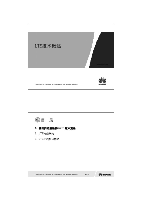
1. 移动网络演进及3GPP 版本演进 2. LTE网络架构 3. LTE无线接口概述
LTE综述(英文版)
UTRAN LONG TERM EVOLUTION IN 3GPPAntti Toskala Harri Holma Kari Pajukoski Esa Tiirola Nokia Networks Nokia Networks Nokia Networks Nokia Networks P.O. Box 301 P.O. Box 301 P.O.Box 319 P.O.Box 31900045 NOKIA GROUPFinland 00045 NOKIA GROUPFinland90651 OULUFINLAND90651 OULUFINLANDA BSTRACTThe 3rd Generation Partner Ship Project (3GPP) produced the first version of WCDMA standard in the end of 1999, which is the basis of the Universal Mobile Telephone System (UMTS) deployed in the field today. This release, called release 99, contained all the basic elements to meet the requirements for IMT-2000 technologies. Release 5 introduced the High Speed Downlink Packet Access (HSDPA) in 2002, enabling now more realistic 2 Mbps and even beyond with data rates up to 14 Mbps. Further Release 6 followed with High Speed Uplink Packet Access (HSUPA) in end of 2004, with market introduction expected in 2007. Alongside with on-going further WCDMA development, work on Evolved Universal Terrestrial Radio Access (UTRA) has been initiated in 3GPP. The objective of Evolved UTRA is to develop a framework for the evolution of the 3GPP radio-access technology towards wider bandwidth, lower latency and packet-optimized radio-access technology with peak data rate capability up to 100 Mbps. This paper introduces the requirements, the current state of progress in 3GPP, findings on the performance, agreed architecture as well as expected schedule for actual specification availability.1.INTRODUCTIONFollowing the first wave of WCDMA based networks rollout with data rates up to 384 kbps both in the uplink and downlink [1], now the High Speed Downlink Packet Access (HSDPA) is being rolled out with 2-3 Mbps practical data rate capabilities and theoretical peak rate of 10 Mbps or even more and with High Speed Uplink Packet (HSUPA) set to follow during 2007 with capability up to 5.7 Mbps in the uplink as well [2].In order to prepare for future needs, 3GPP has initiated activity on the long term evolution of UTRAN (Universal Terrestrial Radio Access Network), which is aiming clearly beyond to what the WCDMA can do with HSDPA or HSUPA in case of uplink. The UTRAN long-term evolution work is looking for the market introduction of Evolved UTRAN (EUTRAN) around 2010, with resulting specification availability planned toward end of 2007. The feasibility study is currently on going and key decisions on the multiple access as well as on the protocol architecture have been recently reached. Feasibility study finalization is expected for September 2006 time frame, after which actual specification development would start. This paper covers in section 2 the requirements for the work defined in 3GPP, and then looks at the network and protocol architecture developments in section 3. Section 4 covers the physical layer technology selection. Section 5 addressed the feasibility study findings on the performance and remaining work and expected schedule is covered in section 6. Conclusions are drawn in section 7.2.REQUIREMENTSFor the long term evolution, clearly more ambitious goals were necessary to make it worth the effort compared with what can be achieved with current system. Thus the following targets were defined [3]:•User plane latency below 5 ms with 5 MHz or higher spectrum allocation. With spectrum allocationbelow, latency below 10 ms should be facilitated.•Reduced control plane latency•Scalable bandwidth up to 20 MHz, with smaller bandwidths covering 1.25 MHz, 2.5 MHz, 5 MHz,10 MHz and 15 MHz for narrow allocations. Also1.6 MHz is considered for specific cases.•Downlink peak data rates up to 100 Mbps•Uplink peak data rates up to 50 Mbps• 2 to 3 times capacity over the existing Release 6 reference scenarios with HSUPA• 2 to 4 times capacity over the existing Release 6 reference scenarios with HSDPA•Improved end user data rates at the cell edge•Support for packet switched (PS) domain onlyWhile big investments have been done and are being done in WCDMA and GSM based networks, also inter-working with WCDMA and GSM is a key requirement for a new system part of the 3GPP technology family. The requirement for handover between legacy systems and E-UTRAN is for services with real time quality a break of 300 ms and for the non-real time services 500 ms would be sufficient.Further there is a desire to have reduced operating cost (often referred as OPEX) and reduced network investment costs (often referred as CAPEX).The agreed baseline assumptions also include 2 receiver antennas in the mobile terminal, which facilitates usage of advanced antenna technologies, such as Multiple Input Multiple Output (MIMO) antenna concepts. Respectively, a typical base station is expected to have two antennas transmit and receive capabilities.The defined mobility support are aiming for optimized performance for mobile speed of less than 15km/h, and high performance for speeds up to 120km/h, and the connection should be maintained with mobile speeds even up to 350 km/h.1-4244-0330-8/06/$20.00 2006 IEEEWORK ARCHITECTUREThe long-term evolution network architecture is characterised by three special requirements:•Support for PS domain only i.e. there will not be connection to circuit switched (CS) domain nodes,such as the Mobile Switching Centre, but speechservices need to be handled as Voice over IP (VoIP)calls.•Tight delay targets for small roundtrip delay. The roundtrip delay target is 5 ms for bandwidths of 5MHz or more. Respective target is 10 ms for thebandwidths of below 5 MHz.•Reduced cost of the systemThe architecture proposals made for the study could be characterized under two categories:•BTS based approach, which adds more functionality for the base station and having all radio relatedfunctionalities in the BTS•Two node architecture for radio protocols with radio related signalling etc. terminating in the node abovebase station.Following the intensive discussion, it was agreed to use two node architecture, with the functionality divided between two network elements, eNode B and access gateway (aGW). Itwas then agreed that radio related signalling (RRC) as well as all layers of retransmission are located in eNode B. MAC layer functionality etc, similar to HSDPA/HSUPA operation, will remain in the eNode B as well. Ciphering and header compressions were decided to be located in aGW, as shown in Fig. 1. The interface connecting aGW and eNode B (BTS) is called S1 interface and that will have some similarity with the Iu interface between the current radio access network and core network, though the functional split is slightly different due to the ciphering and header compression in core network (aGW) side. Further interface called X2 will be defined between eNode Bs for e.g. handover purposes.One of the key issues impacting the architecture was the potential need and type of macro diversity combining to be supported for EUTRAN. As with was decided that there no need for macro-diversity, similar combining functionality as with WCDMA in Radio Network Controller (RNC) [2] was not needed.server for future study.IV.MULTIPLE ACCESS TECHNOLOGY Following the requirements laid down for the multiple access technologies, it has become evident that something else than the use of the current radio interface technology needs to be considered for the radio access supporting up to 100 Mbps and up to 20 MHz bandwidth. While the WCDMA radio interface technology, as described in details in [1], is very efficient for proving (downlink peak) data rates up to 10 Mbps, the requirements such as reaching 100 Mbps peak rate rates cannot be met with WCDMA technology with reasonable mobile terminal complexity. As an example in the downlink direction this would require either multiple 5 MHz carriers or higher chip rate, neither of the solutions very attractive when aiming for very high performance with advanced receivers in the mobile terminal.As this was clearly understood in 3GPP community, the decision was made to adopt the for the uplink direction the Single Carrier FDMA (SC-FDMA) due to the good performance in general and superior properties in terms of uplink signal Peak-to-Average Ratio (PAR) when compared to OFDM in the uplink. In the downlink direction the solution was OFDM, mainly due to the simplicity of the terminal receiver in case of large bandwidths in difficult environment. Also for the network side transmission PAR was not considered such a key problem.The following sub-sections on multiple access details focus on operation with the paired frequency bands (by using frequency division duplex, FDD), though work in 3GPP covers also time division duplex (TDD).A. DownlinkFor downlink, the adoption of OFDMA enabled flexiblesupport of different bandwidth options. The basic OFDMchain is illustrated in Fig. 2 as used for the feasibility studiesat least, though obviously several advanced techniques arebeing considered on top of the basic OFDMA operation.These technologies include frequency domain scheduling,MIMO antenna technologies and variable coding andOne of the key aspects for the air interface is a scalablesolution to support the large number of different bandwidths,starting from 1.25 MHz and all the way to 20 MHz. Thesingle set of parameters for sub-carrier spacing etc. providesupport for different bandwidths by only changing the numberof sub-carriers while keeping the frame length as well assymbol length constant. The parameters defined during thefeasibility study can be found from [6].B. UplinkThe chosen SC-FDMA solutions are based on the use ofcyclic prefix to allow for high performance and lowcomplexity receiver implementation in the base station. Thereare two different variants of SC-FDMA under discussion,which differ from each other only from the spectrum use. Theso called blocked or localized FDMA uses a continuesfrequency band for a single users while with the InterleavedFDMA (IFDMA) the frequency band is used in non-continuous way, as described for example in [3], but only stilltransmitting one modulation symbol in time domain; thusretaining the advantage of low PAR (sometimes referred as crest factor) when compared to OFDMA. With FDMA the type of modulation applied will impact the PAR, but with OFDMA the large number of parallel sub-carriersFigure 3: FDMA and IFDMA principles for frequencydomain generation of signals.make the resulting PAR 2-6 dB higher than FDMA. 3GPP did decide in December 2005 to use FDMA for PAR reasons. The conceptual transmission methods of localized FDMA and IFDMA are illustrated in Fig. 3. OFDM is well know from e.g. the IEEE 802.11 standardsfamily, while FDMA variants with cyclic prefix representnewer proposals for wireless mobile communicationstandards, though it has been published for almost a decadeago, for example in [4].For the uplink considerations the cell edge operation ishighlighted due operator requirements. A mobile data servicethat provides a high data rates in the majority of the cell areais easier to market and sell compared to a mobile data servicethat severely limits the high data rate availability to a smallfraction of the cell area. Hence even a few dBs improvementin PAR is very essential to achieve high data rate availabilityclose to cell edge.The general FDMA transmitter and receiver concept (notdirectly usable for IFDMA) is illustrated in Fig. 4. With thegeneration of IFDMA the block repetition after modulatorshould added or other alternative is the use of FFT/IFFT inthe transmitter as well. Those could be applied to produce theFDMA signal as well, as seen in the example in Fig. 3 withboth IFDMA and FDMA principles illustrated. In case ofIFDMA multiple users can then share the frequency domainresource by using different offset for starting their sub-carrieroccupancy. IFDMA is more sensitive to imperfections likefrequency offset as there are now more borders between usersin frequency domain.In 3GPP discussions an important learning was also that oneshould use instead of PAR, so called Cubic Metric [5] insteadfor describing the impact for the power amplifiers due tosignal envelope variations. The use of CM takes better thepractical amplifier properties into account compared to PAR.The OFDMA and SC-FDMA uplink CM comparison isshown in Fig. 5, indicating the difference depending on themodulation being used. With optimised modulation thedifference may be up to 4 dB in the favour of SC-FDMA.FDMAIFDMATransmitterdomain signal generation.C. Physical layer parameter selectionThe work is on-going to identify the base parameters, such as the transmission time interval (TTI) to be used. For the feasibility study a common parameter set has been agreed, with the example shown in Table 1 for 5 and 10 MHz bandwidths. The common nominator for all bandwidths is theshort TTI of 0.5 ms; this was chosen to enable a very short latency with L1 Hybrid ARQ as already introduced with HSDPA and HSUPA [2].Table 1: Downlink Parameters for 5 and 10 MHz bandwidths. Bandwidth 5 MHz 10 MHz Frame size 0.5 ms Sub-carrier Spacing 15 kHz FFT size 512 1024 Occupied Sub-carriers 301 601 Sampling rate 7.68 MHz 15.36 MHzChannel coding for EUTRAN is attracting optimisation proposals to use different forward error correction than Turbo coding. One reason for discussion with channel coding is the increasing complexity of iterative Turbo decoding with high data rates combined with low latency L1 H-ARQ.Other key parameters have relationship with the multiple access method, such as the sub-carrier spacing of OFDM. The selection is a compromise between support of high Doppler frequency, overhead from cyclic prefix, implementation imperfections etc. The sub-carrier spacing used in feasibility study is 15 kHz. To optimize for different delay spread environments (e.g. ranging from urban pico cells to rural mountain area cells), two cyclic prefix values are to be used. Doppler will also impact the parameterisation, as the physical layer parameterisation needs to allow maintaining the connection at 350 km/h. It has been recognised, however, that scenarios above 250 km/h are specific cases, such as the high-speed train environment. The optimisation target is clearly the lowerCM vs rolloff with different modulationsrolloffC M [d B ]Figure 5: SC-FDMA CM compared to OFDM uplink CM.mobile terminal speeds, below 15 km/h, and performance degradation is allowed for higher speeds.This focus on optimisation for low speeds and urban small cells is visible also in the agreed evaluation scenarios. As part of the physical layer technology selection, the first evaluation scenarios to be considered will be the 3 km/h and 30 km/h scenarios, 2 GHz carrier frequency and 10 MHz bandwidth. The second evaluation scenario is 900 MHz carrier frequency with 1.25 MHz bandwidth. The distance between cell sites is from 500 m to 1732 m.V. PERFORMANCE The interesting question when designing a new system is obviously what is the potential for performance improvement over the existing systems. When looking at the HSPDA performance in [2] is can be seen that especially in the macro-cell environment (and 5 MHz bandwidth) HSDPA is setting rather high bar of the baseline reference performance that is not easily beaten with a classical OFDM approach, as has been discussed in 3GPP previously as well. When one starts to look for higher bandwidths and also environments where multiple antenna solutions could be applied together with advanced methods like frequency domain scheduling, there are opportunities to have better performance level, but not necessary with that high margin as originally aimed (3 to 4 times over the reference). The simulations show 2.5 times over HSDPA Release 6 with 2-antenna Rake receiver in Fig. 6. The spectral efficiency improvements in LTE over HSPA are mainly due to• OFDM with frequency domain equalizationproviding user orthogonality. HSDPA can utilize equalizers to improve the orthogonality in multipath channel, but practical equalizers are not able to remove all intra-cell interference.0.00.20.40.60.81.01.21.41.61.8HSPA Release 6LTEb p s /H z /c e l lFigure 6: Downlink spectral efficiency [6]. • Frequency domain packet scheduling. OFDM allows transmitting using the sub-carrier that has better propagation and interference conditions.• Inter-cell interference rejection combining or interference cancellation can be implemented both in HSDPA and in OFDM, but the potential gains areexpected higher in OFDM with lower complexity due to narrowband carriers. In the uplink direction the use of SC-FDMA offers possibility especially for the cell edge performance as one can create orthogonal uplink which helps the link budget for the users at cell edge. An example reference case is shown in Fig. 7, which shows the uplink performance when compared to the reference HSUPA reference case from 3GPP. With the 1732 meters cell site distance, macro cell layout and 20 dB indoor penetration loss used, the uplink data rate at cell edge remains rather small, and the benefit of the orthogonal uplink with SC-FDMA is fully visible [7]. The results both for the uplink and downlink are for the packet data with full buffer and proportional fair scheduler in the BTS. For the terminal two receiver antennas are assumed while for BTS both twotransmit and receive antennas were used. For shadowing 8 dB standard deviation was assumed and realistic channelestimation was included in the simulation based on the pilot symbols in the data stream.More results can be found in the latest versions of [8] following the finalization of the evaluation of the selected methods against the HSUPA/HSDPA reference cases.VI. 3GPP SCHEDULE Following the creation of the work item for actual specification work, 3GPP has defined the target date for the detailed (stage 3 in 3GPP terms) specification availability by September 2007. The stage 2 (not yet implementation details)level specification is targeted to be approved in March 2007. The expected specification release is Release 8, but that is to be confirmed later asFigure 7: Performance of SC-FDMA vs. WCDMA.3GPP does only decide the actual release once the work iscompleted. Performance requirements are expected to becompleted by December 2007.VII. CONCLUSIONS In 3GPP UTRAN Long Term Evolution work is on going todefine an evolved UTRA/UTRAN system with peak data rate capabilities of up 100 Mbps for downlink and up to 50 Mbps for uplink. Combining this with the 3GPP experience from mobility management ensures the support of seamlessmobility and service offering. The work on-going in 3GPP is not as such replacing WCDMA evolution, but is introducing besides new architecture also new radio access technology. 3GPP has decided to use OFDM in downlink and SC-FDMA in the uplink. In the network architecture flat two node architecture has been chosen. The BTS is handling now all radio related functionality previously divided between BTS and RNC, only PDCP and ciphering are located in the Access Gateway (aGW). R EFERENCES[1] 3GPP technical Report, TR 25.913 version 2.1.0 `` Requirements for Evolved UTRA and UTRAN '', 3GPP TSG RAN#28, Quebec, Canada,June 1-3, 2005, Tdoc RP-050384. [2] Holma, H. and Toskala, A., ``WCDMA for UMTS'', 3rd edition , Wiley,2004. [3] Sorger, U., De Brock, I. and Schnell, M., “Interleaved FDMA –A NewSpread Spectrum Multiple Access Scheme ”, IEEE Globecomm 1998. [4] Czylwik, A., `` Comparison between adaptive OFDM and single carriermodulation with frequency domain equalisation '', IEEE VehicularTechnology Conference 1997, VTC-97, Phoenix, pp. 863-869. [5] Holma H. and Toskala A., “HSDPA/HSUPA for UMTS, Wiley, 2006 [6] Nokia, “LTE Evaluation Results”, May 2006, Shanghai, China, TSGRAN WG1#45, May 8-12, 3GPP Tdoc R1-061238. [7] Nokia, “System Level Evaluation of the Concepts” November 2005,Seoul Korea, TSG RAN WG1#43bis, 3GPP Tdoc R1-051411.[8] 3GPP technical Report, TR25.814 v1.2.1 Physical Layer Aspects for Evolved UTRA '', 3GPP TSG RAN#31, Hainan, China, March 8-10,2006, 3GPP Tdoc RP-060201.。
LTE现状及未来发展综述

L TE现状及未来发展综述张同须(中国移动通信集团设计院有限公司北京100080)摘 要 后3G时代的LTE是全球移动通信产业的主流演进方向。
本文详细论述了LT E的发展状况、LTE的技术特点以及未来LTE的演进技术。
同时特别针对T D-LTE的发展提出了一些建议。
关键词 LTE OF DM MIMO张同须 教授级高级工程师,现任中国移动通信集团设计院副院长兼总工程师。
北京邮电大学兼职教授,工业和信息化部通信科学技术委员会委员。
多年来一直从事大型电信网络的工程设计工作,现致力于IP及宽带移动通信网络的设计和研究工作。
曾组织并承担C HINANE T等大型全国性IP骨干网络的工程设计,并编写了有关的技术体制和设计规范,获多个国家及部级奖项,发表数十篇论文,出版两本专著。
2001年享受国务院政府特殊津贴。
1LTE发展状况LT E(Long T erm E volu tion)是3GPP于2004年11月启动的UMTS技术长期演进项目。
LT E分为FDD方式的LT E和T DD方式的LT E,其中T DD方式的LT E又由于演进路线的不同分为LTE TDD1和LT E T DD2。
我国从2005年开始推动LT E的TDD方案即LTE TDD2方式的研究并被3GPP接受,之后由我国大力推动并通过多方努力,目前两种TDD方式已经融合为一种即TD-LT E。
T D-LTE也被同时确定为T D-SCDMA标准的后续演进技术。
1.1标准进展LT E标准制定工作进展很快。
尤其是最近几年,3GPP加快了LT E的标准化工作。
一方面是由于无线新技术的逐步完善已基本可以实用化,更主要的是由于现有的包括3G在内的移动通信网络已经逐渐不能满足用户的需求。
3GPP于2009年3月发布第一版(R elease 8),R8版本为LT E标准的基础版本;于2010年3月发布第二版(R elease9),R9版本为LT E的增强版本,主要增加了支持多流Beamfo rmin g、eMBMS、SON、Home eNB等新功能。
LTE技术发展综述(大工)
LTE技术发展综述摘要LTE 已经具有相当明显的4 G 技术特征,它是当前移动宽带通信系统最受关注的热点之一。
本文首先对LTE技术发展背景,技术优势、系统结构进行了概述。
然后,着重分析了LTE 的关键技术,并对其最新进展和应用情况进行了简要的介绍。
关键词: LTE OFDM MIMOOverview of the LTE developmentAbstractLTE has possessed extraordinary distinct characteristics of 4G technology ,it is one of hot research topics in mobile broadband communication system,which should pay more attention at present. This paper first give an overview of the development background, technical advantages, system structure for LTE. Then, this paper analyzes the key technology of LTE, and introduces its latest development and application.Keyword: LTE OFDM MIMO一、前言3G对移动通信产生了巨大的影响,无所不在的宽带无线网络给人们的生活和工作带来了前所未有的体验,并且摆脱了场地和环境的束缚。
但随着人们更加丰富多彩的移动互联网业务的不断增加,2 Mbit/s 的WCDMAR99传输速率、14.4 Mbit/s R5HSDPA的峰值速率已远远不能满足人们的需求。
但由于过去CDMA专利掌握在高通(Qualcomm)手中,致使厂商及3GPP在布局上束手束脚。
LTE技术介绍PPT课件

2013.1.15
目录
1 LTE简介 2 EPS系统架构与功能 3 空中接口协议 4 LTE无线传输关键技术 5 基本信令流程 6 业务连续性 7 IMS系统介绍
LTE简介
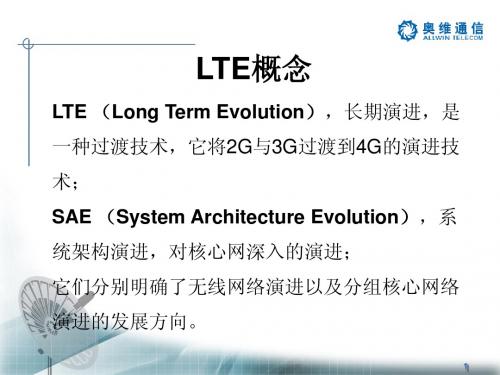
什么是LTE
LTE(Long Term Evolution,长期演进)项目是3G的演进,始于2004年3GPP的多伦多 会议。 LTE并非人们普遍误解的4G技术,而是3G与4G技术之间的一个过渡,是3.9G的全球 标准,它改进并增强了3G的空中接入技术,为用户提供更高速率的网络业务应用,改 善了小区边缘用户的性能,提高小区容量和降低系统延迟。 LTE包括TDD(时分双工)、FDD(频分双工)两种双工模式。中国移动采用TDD ( 时分双工)模式。 LTE的演进方向是LTE-Advanced。
UTRAN SGSN
GERAN
S3
HSS
S1-MME
LTE-Uu
UE
E-UTRAN
MME S11
S10
S6a
S4 S-GW
PCRF
S12 Gx
Rx
S5
SGi
PND-GW
运营商IP业务
S1-U
3GPP接入EPS非漫游架构图
hPLMN vPLMN
UTRAN GERAN
SGSN S3
PCRF
HSS
Gx
Rx
2、MME
MME主要负责用户及会话管理的所有控制平面功能,包括NAS信令及其安全,跟踪区(Tracking Area)列表的管理,PDN-GW和S-GW节点的选择,跨MME切换时对新MME的管理,在向2G/3G系统切 换过程时,SGSN的选择、鉴权、漫游控制及承载管理,3GPP不同无线接入网核心节点之间的移动性管理 ,以及UE空闲状态的移动性管理。
LTE概述及基本原理
12 Minutes 1 Hour
29 Hours 6+ Days
1Minutes 18 seconds
6Minutes 31Seconds
3 Hours 15 Minutes 17 Hours 22 Minutes
ADSL/ HSPA 2Mbps
1 Second
20 Seconds
Page 8
LTE工作频段
3GPP定义的E-UTRA频段
iPhone 5 LTE频段(A1429)
中国LTE频段 •2.6G 190M都用作TDD •1800M高30M还没有分配 •潜在LTE频段 •450MHz(3M、5M带宽) •700MHz •1.4G(TDD) •3.5GHz
TDD频段 B34:A频段,2.1G B38:D频段,2.6G B39:F频段,1.9G B40:E频段,2.3G
• 核心网:用户面和控制面分离
• 原有SGSN实体分解为MME(控制面实体)和Gateway(用户面实体)
Page 12
3G->LTE演进目标网--- 规模部署EPC网络,支持全网融合
GPRS UMTS LTE eHRPD
BTS BSC/PCU NodeB RNC eNodeB
SGSN
Gb
EPC(Evolved Packet Core)
Page 7
LTE能做啥?更多应用,需更多频谱与制式以及更灵活的承载
个人-体验更好
1. 便携接入 2. 移动热点 3. 移动多媒体
业务 4. 基于云计算
的业务 5. VoIP 6. …
家庭-减少宽带空白 区,丰富生活
1. 无线DSL 2. 视频通话 3. 应用商城 4. OTT 5. IPTV 6. VOD 7. …
LTE概述
1、系统消息广播和寻呼
2、建立、管理、释放RRC连接 3、RRC信令的加密和完整性保护 4、RB管理 5、移动性管理 6、广播/多播服务支持 7、NAS直传信令传递
24
数字中继
中继就是通过在基站(eNB)和移动台(UE)之间增加中 间节点,对基站的发射信号或者终端的发射信号进 行再生、放大处理后,再转发给终端或者基站,以 此提高信号传输的质量和可靠性。
IPv4
Ethernet MAC Ethernet PHY
Appl. stack ARM BSP PC202 HW
GPIO
Accel erator
picoArray
CNE running peer RANAP and call control functions
RF Module
JTAG
46
特点:
用户可以自己购买
1、低成本:Femtocell结构简单,与传统基站相比,价格低廉,
2、用户安装:支持即插即用,用户可以自行安装Femtocell终
端,只需要运营商进行激活
3、宽带接入:Femtocell是基于IP协议的可以通过现有的DSL、 cable或光纤等宽带手段接入移动运营商的网络。 4、低功率:Femtocell的发射功率为10~100mW,与Wi-Fi接 入点类似。
这种类型中继节点控制独立的一个小区; 从UE的角度来看连接到这一类型的中继和连接到普通基 站节点没有任何差别; 从所属的协议层来看,这一类型的中继一般为层3中继。
30
Type II 中继: 这种类型中继没有属于自己的小区ID,中继节点被看 作是归属基站的一部分
这类型中继,有时需要考虑与基站的协作,以达到最
35
家庭基站的网络架构
移动通信知识点总结LTE

移动通信知识点总结LTE一、LTE的发展历程1. LTE的前身LTE技术的前身是3G技术,即第三代移动通信技术。
在3G时代,移动通信领域主要使用的是WCDMA(Wideband Code Division Multiple Access)和CDMA2000(Code Division Multiple Access 2000)等技术标准。
这些技术虽然在当时是先进的,但是在面对越来越大的数据流量和更高的用户需求时,已经不能满足现代移动通信的要求。
2. LTE的发展随着移动通信技术的飞速发展,LTE技术应运而生。
LTE技术是一种全IP的无线网络技术,它将移动通信网络中的语音、数据和视频等业务都统一在一个IP网络中传输,从而提供更加高效、更加灵活的无线通信服务。
LTE技术的出现,对整个通信行业产生了深刻的影响,也标志着4G时代的到来。
3. LTE的商用化LTE技术于2009年实现了商用化,之后迅速在全球范围内推广。
LTE网络的建设不仅提高了移动通信的速度和容量,还大大提高了用户体验。
目前,LTE技术已经成为全球范围内主流的移动通信技术之一,得到了广泛的应用。
二、LTE技术架构1. LTE网络架构LTE网络主要由三个部分组成,即用户设备(UE)、E-UTRAN(Evolved UMTS Terrestrial Radio Access Network)和EPC(Evolved Packet Core)。
用户设备是指移动终端设备,E-UTRAN是LTE网络的接入网,负责与用户设备进行无线通信,EPC是LTE网络的核心网,负责处理数据传输和呼叫控制等核心功能。
2. LTE的接入方式在LTE网络中,采用了OFDMA(Orthogonal Frequency Division Multiple Access)和SC-FDMA(Single Carrier Frequency Division Multiple Access)这两种多址技术。
LTE基础知识介绍
LTE基础知识介绍LTE(长期演进技术,Long-Term Evolution)是第四代移动通信网络技术,它提供更高的数据传输速率、更低的延迟和更好的系统容量,是3G网络的升级版本。
本文将对LTE的基础知识进行介绍。
1.LTE的原理和特点LTE使用OFDMA(正交频分复用)和SC-FDMA(单载波频分多址)技术,使得多个用户同时在不同的子载波上传输数据,减少了不同用户之间的干扰,提高了网络容量。
同时,LTE还引入了MIMO(多输入多输出)技术,可以同时传输多个数据流,进一步提高了数据传输速率。
2.LTE的网络架构LTE的网络架构由多个基站(Base Station)、eNodeB(核心网连接点)、MME(移动管理实体)、SGW(服务网关)和PGW(流量网关)组成。
基站通过无线信道与用户设备进行通信,而eNodeB则负责管理和控制无线资源分配。
MME负责控制用户连接和鉴权,SGW和PGW负责处理数据的分发和转发。
3.LTE的频段LTE可以在多个频段工作,包括700MHz、800MHz、1800MHz、2100MHz、2300MHz和2600MHz等频段。
不同的频段在不同的区域具有不同的特点,有些频段适合广覆盖,有些适合高容量。
同时,LTE还支持动态频谱共享,可以根据实际需求灵活地配置频段。
4.LTE的速率5.LTE的特殊技术LTE还引入了一些特殊技术,以提高系统性能。
其中包括小区间协作(Inter-Cell Interference Coordination)技术,可以减少小区之间的干扰;自适应调制和编码(AMC)技术,可以根据信道质量选择最佳的调制方式和编码方案;和动态分组调度(Dynamic Packet Scheduling)技术,可以根据用户需求动态地分配无线资源。
6.LTE的应用LTE技术被广泛应用于移动通信和互联网领域。
它可以提供高速的数据传输,支持实时视频、高清音频和大型文件传输。
同时,由于LTE具有较低的延迟和较好的稳定性,还可以应用于物联网、自动驾驶和远程医疗等领域。
001 LTE及LTE-Advanced标准介绍

20MHz
Option 1
20MHz
Option 2
Option 3
2012-6-21
下行MIMO
下行MIMO增强 • 空间复用技术
– 8天线码本设计 • 以高相关信道,尤其是小间距双极化天线阵为最主要的优化场景; • 以Rank ≤4码本优化设计为主要优化目标; • 以SU-MIMO和MU-MIMO的性能作为主要优化参考指标;
TDD帧结构
BF 帧结构融合 R10/9起动
R8标准奠定了LTE发展的基石
LTE-A R10标准进展里程碑
LTE-Advanced是LTE后向兼容的演进系统,作为IMT-Advanced技术 提案提交到ITU。
R10标准满足ITU规定的IMT-Advanced的最小需求
LTE/LTE-Advanced标准综述 LTE A R10标准化介绍 LTE-A CCSA LTE行标介绍 ITU IMT-Advanced介绍
transport block Channel Ch l coding Modulation RB mapping
Component carrier 1
transport block Channel Ch l coding Modulation RB mapping
Component carrier 2
下行MIMO-BF
智能天线增强型技术
– 双流Beamforming 在R9版本中已经实现,支持最多4用户单流MU-MIMO和 两流SU-MIMO; – 利用TDD信道对称性,基于专用导频的信道估计,优化MU-MIMO的实现 性能; – 性能已经在现有系统中得到初步验证。 波束赋形(BF) 降低干扰 提升覆盖半径 双流BF技术
LTE介绍

一LTE市场背景和技术背景介绍伴随GSM等移动网络在过去的二十年中的广泛普及,全球语音通信业务获得了巨大的成功。
目前,全球的移动语音用户已超过了18亿。
同时,我们的通信习惯也从以往的点到点(Place to Place)演进到人与人。
个人通信的迅猛发展极大地促使了个人通信设备的微型化和多样化,结合多媒体消息、在线游戏、视频点播、音乐下载和移动电视等数据业务的能力,大大满足了个人通信和娱乐的需求。
另外,尽量利用网络来提供计算和存储能力,通过低成本的宽带无线传送到终端,将有利于个人通信娱乐设备的微型化和普及。
GSM网络演进到GPRS/EDGE和WCDMA/HSDPA网络以提供更多样化的通信和娱乐业务,降低无线数据网络的运营成本,已成为GSM移动运营商的必经之路。
但这也仅仅是往宽带无线技术演进的一个开始。
WCDMA/ HSDPA与GPRS/EDGE相比,虽然无线性能大大提高,但是,在IPR的制肘、应对市场挑战和满足用户需求等领域,还是有很多局限。
由于CDMA通信系统形成的特定历史背景,3G所涉及的核心专利被少数公司持有,在IPR上形成了一家独大的局面。
专利授权费用已成为厂家承重负担。
可以说,3G厂商和运营商在专利问题上处处受到制肘,业界迫切需要改变这种不利局面。
面对高速发展的移动通信市场的巨大诱惑和大量低成本,高带宽的无线技术快速普及,众多非传统移动运营商也纷纷加入了移动通信市场,并引进了新的商业运营模式。
例如,Google与互联网业务提供商(ISP)Earthlink合作,已在美国旧金山全市提供免费的无线接入服务,双方共享广告收入,并将广告收入作为其主要盈利途径,Google更将这种新的运营模式申请了专利。
另外,大量的酒店、度假村、咖啡厅和饭馆等,由于本身业务激烈竞争的原因,提供免费WiFi 无线接入方式,通过因特网可以轻易的查询到这类信息。
最近,网络服务提供商“SKYPE”更在这些免费的无线宽带接入基础上,新增了几乎免费的语音及视频通信业务。
讲解认识LTE网络
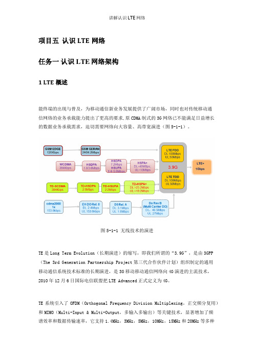
项目五认识LTE网络任务一认识LTE网络架构1 LTE概述能终端的出现与普及,为移动通信新业务发展提供了广阔市场,同时也对传统移动通信网络的业务承载能力提出了更高的要求,原CDMA制式的3G网络已不能满足日益增长的数据业务承载需求,迫切需要网络向大容量、高带宽演进(图5-1-1)。
图5-1-1 无线技术的演进TE是Long Term Evolution(长期演进)的缩写,即我们所谓的“3.9G”,是由3GPP (The 3rd Generation Partnership Project第三代合作伙伴计划)组织制定的通用移动通信系统技术标准的长期演进,是3G移动移动通信网络向4G演进的主流技术,2010年12月6日国际电信联盟把LTE Advanced正式定义为4G。
TE系统引入了OFDM(Orthogonal Frequency Division Multiplexing,正交频分复用)和MIMO(Multi-Input & Multi-Output,多输入多输出)等关键技术,显著增加了频谱效率和数据传输速率,它支持1.4MHz,3MHz,5MHz,10MHz,15MHz和20MHz等多种带宽分配,且能在全球主流2G/3G频段平滑演进,因而频谱分配更加灵活,系统容量和覆盖也显著提升。
LTE系统网络架构更加扁平化简单化,减少了网络节点和系统复杂度,从而减小了系统时延,也降低了网络部署和维护成本。
LTE系统支持与其他3GPP 系统互操作。
因此,与其他无线技术相比,LTE具有更高的传输性能,且同时适合高速和低速移动应用场景。
TE系统根据双工方式不同分为TDD-LTE (Time Division Duplexing)和FDD-LTE (Frequency Division Duplexing),二者技术的主要区别在于空口的物理层上。
TDD 系统上下行则使用相同的频段在不同的时隙上传输,具有有着较高的频谱利用率,FDD 系统空口上下行采用成对的频段接收和发送数据,在频谱效率与VOIP容量方面稍有优势。
- 1、下载文档前请自行甄别文档内容的完整性,平台不提供额外的编辑、内容补充、找答案等附加服务。
- 2、"仅部分预览"的文档,不可在线预览部分如存在完整性等问题,可反馈申请退款(可完整预览的文档不适用该条件!)。
- 3、如文档侵犯您的权益,请联系客服反馈,我们会尽快为您处理(人工客服工作时间:9:00-18:30)。
语音和数据ARPU趋势
语音和数据ARPU趋势 25 20 15 10 5 0 2006 2007 2008 2009 2010 2011 2012
用户数(百万)
增长率
语音ARPU 数据ARPU
用户数仍有增长,但增长率下降
语音ARPU不断下降,数据ARPU逐年上升
移动通信不断提升带宽
PON1~10Gbps VDSL2 >200Mbps 600ms
100Mbps
ADSL2+ 24Mbps WR5 14.Mbps
LTE >100Mbps 600ms
10Mbps ADSL 1.2 Mbps
ADSL2 12Mbps
1Mbps
ADSL 256Kbps Analog 56Kbps
150ms WR99 384Kbps 100ms 55ms GPRS 53.6Kbps 40ms 15ms
来等方面进行讨论。
目 录
1. LTE驱动力 2. LTE技术亮点及优势 3. LTE产业进展
4. LTE部署策略
5. 移动通信网络演进趋势
LTE发展驱动
语音收入下降 增加收入:提升带宽,引入新业务,增加业务量
现网成本
网络成本高
LTE成本
降低成本:降低数据业务每bit成本,增加收益
WiMAX LTE
仿真条件
带宽:10MHz MIMO: DL: 2x2, UL 1x2, 终端速度:3km/h
小区距离:500m TDD上下行比例:1:1 VoIP速率:12.2k AMR
问 题
LTE发展的驱动力有哪些? LTE为何是“长期”演进? 哪些制式可以演进到LTE?
LTE的主要设计目标有哪些?
ANR:通过UE的测量报告自动的配臵邻区,当网络拓扑发生
变化时,邻区列表也会动态的调整
MRO- 切换优化
功能:通过不同切换情况的识别,并 进行统计,根据异常切换统计结果对 切换参数进行优化,改善网络性能
常见的异常切换如下:
乒乓切换 切换过早 切换过晚
LTE技术优势1:高速、高效、低时延
Web网页访问
下载5M音乐
下载25M视频
下载750M视 频
1 Hour
29 Hours
6Minutes
31Seconds 3 Hours 15 Minutes
1 Minute
40Seconds 50 Minutes
25 Seconds
12 Minutes 30 Seconds
OK,等着 8 Seconds 2 Seconds
•
OFDM技术
Single Carrier Multi-carrier
frequency
frequency
OFDM: Orthogonal Frequency Division Multiplexing
OFDM
正交频分复用
frequency
MIMO技术
MIMO: Multiple input and multiple output
S4 Gx S5/8
Operator Service Network
E-UTRAN
S1-U
SGi
Internet
eNodeB
A10/A11
Serving GW
S2a
PDN GW
cdma2000
BTS
BSC PDSN
Corporate Internet
SAE基本网元概述
MME • • • 移动性管理 会话管理 用户鉴权和密钥管 理 NAS层信令的加密 和完整性保护 TA LIST管理 P-GW/S-GW选择 Serving Gateway PDN Gateway • • 分组路由和转发 3GPP和非3GPP网 络间的Anchor功 能[HA功能] UE IP地址分配,接 入外部PDN的网关 功能 计费和QoS策略执 行功能 基于业务的计费
200ms
100ms
50ms 15ms 2015
Analog 28.8Kbps
<1990
1995
2000
2002
2005
2007
2009
2011
移动用户享有固网用户同等的业务感受
LTE的新业务
业务类型 SMS GPRS/EDGE ★ UMTS ★ LTE ★
MMS
Web 浏览 Email 高速web浏览 视频电话 普通网络游戏 企业VPN 高清视频点播 基于MBMS的移动视频广告
X2
S1
S1
X2
S1
E-UTRAN
LTE/SAE网络结构
SAE
SGSN
Gb
EPS (Evolved Packet System)
Control plane User plane
GPRS
BTS
BSC/PCU
Iu S3 S6d S6a
HSS
PCRF
S9
S10
UMTS
NodeB
RNC
S1-MME
MME
S12 S11
SON
优势:
实现快速组网
缩短网络规划时间 简化网络维护和调整,降低对维护
人员技术要求
主要功能
自配臵
ANR(自动邻区规划)
MRO(切换自优化)
网络自配置
自配臵功能可以大大减少网络部署的工作量,支持第三方配臵工具
ANR-自动邻区优化
OSS
PCI:Physical Cell ID
CGI: Cell Global ID
无线技术向LTE演进
HSPA+ WCDMA 384Kbps GSM EDGE 120Kbps HSDPA 1.8/3.6Mbps GSM GERAN 240K-2Mbps
TD-HSPA+ DL:>25.2Mbps UL:>19.2Mbps
HSDPA 7.2Mbps HSUPA 1.4~5.8Mbps
LTE技术优势2:简单、灵活和统一的网络
传统网络
业务 信令 GGSN SGSN 业务 信令
扁平网络
SAE-GW
MME
VS
RNC
NodeB
NodeB
eNodeB
eNodeB
传统网络 语音
TDM/ATM/IP
业务(语音数据)全IP,承载全IP
CS
ATM
NodeB
RNC
VS
eNodeB
IP
PS
PS
语音+数据
★
★ ★
★
★ ★ ★ ★ ★ ★
★
★ ★ ★ ★ ★ ★ ★ ★
Mobile Web2.0
高端网络游戏
★
★
LTE用户体验
Modem/ ADSL/
先做一下 其他事情
ADSL/ HSPA 2Mbps
1 Second
20 Seconds
ADSL /HSPA 8Mbps
0.3 Second
5 Seconds
LTE综述
前 言
电信技术业务移动化、宽带化和IP化的趋势日益明显,移动 通信技术处于网络技术演进的关键时期,也就在此时,LTE (Long Term Evolution,长期演进)与大家见面了。 LTE 作为下一代移动通信的统一标准,具有高频谱效率、高 峰值速率、高移动性和网络架构扁平化等多种优势。 本课就LTE驱动力、产业链现状、部署策略和移动通信的未
峰值速率:
下行峰值100Mbps,上行峰值50Mbps
时延:
控制面 IDLE —〉ACTIVE: < 100ms
用户面 单向传输: < 5ms
移动性:350 km/h(在某些频段甚至支持500km/h) 频谱灵活性:
带宽从1.4MHz~20MHz(1.4、3、5、10、15、20) 支持全球2G/3G主流频段,同时支持一些新增频段
4 Minutes 10 Seconds 1 Minutes 20 Seconds
下载高清视频
6+ Days
17 Hours
22 Minutes
4 Hours
27 Minutes
67 Minutes
22 Minutes
6 Minutes
忙别的事情或晚上进行
离开一会儿
带宽提升后数据业务量快速上升
LTE部署后又将上升多少倍?
cdma2000 1x 153.6kbps
EV-DO Rel. 0 DL: 2.4Mbps UL:153.6kbps
D0 Rel. A DL: 3.1Mbps UL: 1.8Mbps
Do Rev B (Multi Carrier DO) DL:46.5Mbps UL: 27Mbps
LTE主要设计目标
数据
LTE技术优势3:更低成本(节省TCO)
CAPEX
Cost per Mbyte
GSM Module@20MHz
~50 % ~70 %
LTE Module@20MHz
OPEX-SON引入
3G
HSPA
HSPA+
LTE
问 题
网络结构扁平化有何优点?SAE的主要网元有哪些?
WiMAX的领先
应对竞争:应对WiMAX阵营的竞争
语音收入下降
全球用户增长趋势
全球用户数增长趋势 6,000 5,000 4,000 3,000 2,000 1,000 0 2006 2007 2008 2009 2010 2011 2012 10.0% 5.0% 0.0% 25.0% 20.0% 15.0%