D1621-00 compressive
00美标规范目录

混凝土相关规范American Concrete InstituteACI 117-90 Specifications for Tolerances for Concrete Construction andMaterials and CommentaryACI 207.1R-05 Guide to Mass ConcreteACI 207.4R - 05 Cooling and Insulating Systems for Mass ConcreteACI 237R - 07 Self-Consolidating ConcreteACI 301∕301M-05 Specifications for Structural ConcreteACI 302.IR-04 Guide for Concrete Floor and Slab ConstructionACI 304R - 00 Guide for Measuring, Mixing, Transporting and PlacingConcreteACI 304.1R-92 (r 2005) Guideline to the Use of Preplaced Aggregate Concrete forStructural and Mass ApplicationsACI 304.2R - 96 Placing Concrete by Pumping MethodsACI 305R - 99 Hot Weather Concreting - Incorporating Errata: 6/15/06 ACI 306R - 88 (r 2002) Cold Weather ConcretingACI 306.1 -90 (r 2002) Standard Specification for Cold Weather ConcretingACI 308R-01 Guide to Curing ConcreteACI 308.1 -98 Standard Specifications for Curing ConcreteACI 309R - 05 Guide for Consolidation of ConcreteACI 309.2R - 98 Identification and Control of Visible Effects of Consolidation on Formed Concrete SurfacesACI 309.3R -92 (r 1997) Guide to Consolidation of Concrete in Congested Areas.ACI 315-99 Details and Detailing of Concrete ReinforcementACI 318-99Building Code Requirements for Structural Concrete and Commentary ACI 347 - 04 Guide to Formwork for ConcreteACI 349∕349R - 01 ACI 350-06 Code Requirements for Nuclear Safety Related ConcreteStructures Code Requirements for Environmental Engineering Concrete Structures and CommentarySP-66 - 04 ACI Detailing Manual American Iron and Steel InstituteAISI Design Specification - 01 North American Specification for the Design of Cold- Formed Steel Structural MembersAmerican Society of Mechanical EngineersNQA -1-94 Quality Assurance Requirements for Nuclear Facility ApplicationsAmerican Society of Nondestructive TestingSNT-TC-IA-Ol Recommended Practice No. SNT-TC-IA 2001Nuclear Regulatory CommissionRG 1.38 Quality Assurance Requirements for Packaging, Shipping,Receiving, Storage, and Handling of Items for Water- Cooled Nuclear Po∖PlantsAmerican Society for Testing and MaterialsASTM A 29/A 29M - 05 Standard Specification for Steel Bars, Carbon and Alloy, Hot-Wrought, General Requirements forASTM A 36 - 05 Standard Specification for Carbon Structural SteelASTMA 185/A 185M-07 Standard Specification for Steel Welded Wire Reinforcement, Plain, for ConcreteASTM A 519-06 Standard Specification for Seamless Carbon and Alloy Steel Mechanical TubingASTM A615∕A615M-07 Standard Specification for Deformed and Plain Carbon - Steel Bars for Concrete ReinforcementASTMD 1752-04a Standard Specification for Preformed Sponge Rubber Corkand Recycled PVC Expansion Joint Fillers for Concrete Pavingand Structural ConstructionASTM D 2628-91 (r 2005) Standard Specification for Preformed Polychloroprene Elastomeric Joint Seals for Concrete Pavements Standard Specification for Lubricant for Installation ofASTM D 2835 - 89 (r 2007) Preformed Compression Seals in Concrete Pavements ASTM D 2842 - 06 Standard Test Method for Water Absorption of RigidCellular PlasticsStandard Test Method for Surface BurningASTM E 84 - 08 Characteristics of Building MaterialsASTM E 94 - 04 Standard Guide for Radiographic ExaminationStandard Test Methods for Water Vapor Retarders Used ASTME 154-99 (r 2005) in Contact with Earth Under Concrete Slabs, on Walls or asGround CoverStandard Test Method for Determining FF Floor Flatness ASTME 1155 -96 (r 2001) and FL Floor Levelness NumbersAmerican Welding SocietyAWS A5.1∕A5.1M-04 Specification for Carbon Steel Electrodes for Shielded Metal Arc WeldingAWS A5.5∕A5.5M - 06 Specification fbr Low-Alloy Steel Electrodes for Shielded Metal Arc WeldingAWS A5.20∕A5.20M - 05 Specification fυr Carbon Steel Electrodes for Flux Cored Arc WeldingAWSD1.1∕D1.1M-O6 Structural Welding CodeAWSD1.4∕D1.4M-05 Structural Welding Code - Reinforcing Steel 29 CFR 1910 Occupational Safety and Health StandardsIOCFR 50 Appendix B Quality Assurance Criteria fbr Nuclear Power Plants and Fuel Reprocessing Plants, Nuclear Regulatory CommissionConcrete Reinforcing Steel Institute (CRSI)Placing Reinforcing Bars - 8th EditionHandbook for Concrete and Cement, Corps of Engineers, U.S. ArmySpecification for Rubber WaterstopCRD-C 513-74Specification for Polyvinylchloride Waterstop CRD-C 572 - 74。
LCD驱动芯片TM1621D『官方最新规格书』

80
150
5V VOL=0.5V
150
250
IOH2 LCD 公共口源电流 3V VOH=2.7V
-80
-120
5V VOH=4.5V
-120
-200
IOL3 LCD 段管脚漏电流 3V VOL=0.3V
60
120
5V VOL=0.5V
120
200
IOH3 LCD 段管脚源电流 3V VOH=2.7V
-40
-70
5V VOH=4.5V
-70
-100
RPH 上拉电阻
3V DATA,/WR, 40
80
5V /CS
30
60
TM1621D
3.0
V
5.0
V
mA
mA
mA
mA uA uA
uA uA
uA uA
uA
uA
150
Kohm
100
Kohm
交流电气特性
符号
描述
fSYS1
系统时钟
fSYS2 fSYS3 fLCD
BIAS 1/3
TOPT TNORMAL 注: X:0或1;
101
D
写数据到RAM
a5a4a3a2a1a0d0d1d2d3
10000000000X
C
关闭系统振荡器和LCD 偏压
发生器
10000000001X
C
打开系统振荡器
10000000010X
C
关闭LCD 偏压发生器
10000000011X
C
打开LCD 偏压发生器
I 负电源、地 I LCD 电源输入 I 正电源 O LCD 公共输出口
intel c621a参数 -回复
intel c621a参数-回复Intel C621A是一款高端服务器芯片组,它具有出色的性能和扩展性,适用于大型数据中心和企业级应用。
本文将详细介绍Intel C621A的特点和参数,并一步一步回答与其相关的问题。
首先,让我们了解一下Intel C621A的主要特点。
该芯片组采用了14纳米工艺制造,集成了多个关键功能,以满足企业级应用对高性能和扩展性的需求。
这些功能包括支持高达24个PCIe 3.0通道以及支持多达20个SATA 3.0、8个SAS 3.0和4个USB 3.0端口。
此外,Intel C621A还支持最多4个DDR4内存通道,最高支持2666MHz的内存速度,并且支持最多2个Intel Xeon处理器。
接下来,让我们来回答一些与Intel C621A相关的问题。
1. Intel C621A适用于哪些应用?由于其强大的性能和扩展性,Intel C621A特别适用于大型数据中心和企业级应用。
它可以支持高并发的计算任务和大规模数据存储,同时还能够满足企业级应用对稳定性和可靠性的需求。
2. Intel C621A支持的最大内存容量是多少?Intel C621A芯片组最多支持4个DDR4内存通道,每个通道最高支持2666MHz的内存速度。
因此,它可以支持非常大的内存容量。
根据不同的服务器制造商和型号,Intel C621A支持的最大内存容量可能在1TB 到4TB之间。
3. Intel C621A支持的主要扩展接口有哪些?Intel C621A芯片组支持多达24个PCIe 3.0通道,可用于连接各种扩展卡和加速卡,如图形处理器和网络适配器。
此外,它还支持20个SATA 3.0接口、8个SAS 3.0接口和4个USB 3.0接口,以满足不同的扩展需求。
4. Intel C621A与其他芯片组相比有何优势?相比其他芯片组,Intel C621A具有更高的性能和扩展性。
首先,它支持最多2个Intel Xeon处理器,可以实现更高的计算性能。
dell戴尔poweredger720服务器错误代码二

dell戴尔poweredger720服务器错误代码二Dell/戴尔 PowerEdge R720 服务器错误代码二本空间免费为已购买客户提供终身售前以及售后技术支持140错误代码消息信息MEM0701消息Correctable memory error rate exceeded for .(的可纠正内存错误比率超限。
)详细信息内存可能无法操作。
这是未来可能发生的不可纠正错误的早期迹象。
操作重新安装内存模块。
如果问题仍然存在,请参阅“获得帮助”。
MEM0702消息Correctable memory error rate exceeded for .(的可纠正内存错误比率超限。
)LCD 消息Correctable memory error rate exceeded for . Re-seat memory.(的可纠正内存错误比率超限。
重新安装内存。
)详细信息内存可能无法操作。
这是未来可能发生的不可纠正错误的早期迹象。
操作重新安装内存模块。
如果问题仍然存在,请参阅“获得帮助”。
MEM1205消息Memory mirror redundancy is lost. Check memory device at location(s) .(内存镜像冗余已丢失。
检查位置的内存设备。
)LCD 消息Memory mirror lost on . Power cycle system.(的内存镜像丢失。
将系统关闭后再打开。
)详细信息内存可能安装不正确,配置错误,或者发生故障。
操作检查内存配置。
重新安装内存模块。
如果问题仍然存在,请参阅“获得帮助”。
MEM1208消息Memory spare redundancy is lost. Check memory device at location.(内存备用冗余已丢失。
检查位置的内存设备。
)LCD 消息Memory spare lost on . Power cycle system.(内存备份丢失。
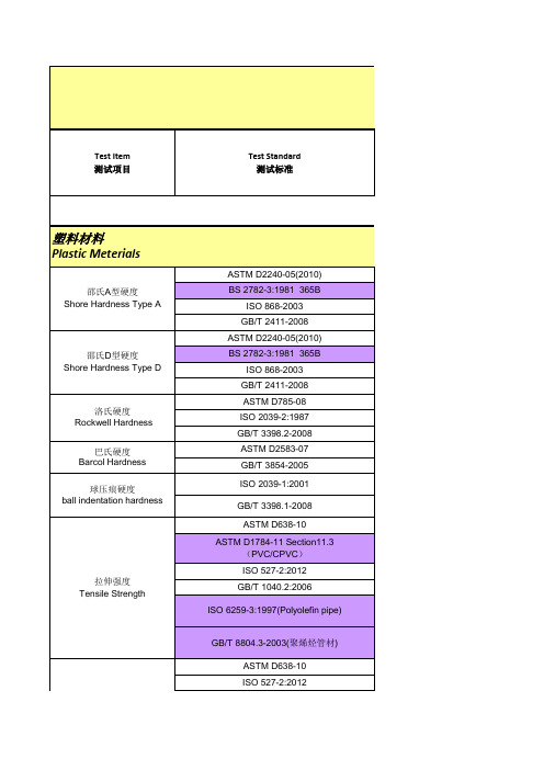
Polymer Material and Reliability Testing V6 0
ISO 4662-2009 Pendulum Method
回弹性 Rebound Resilience
回弹性 Rebound Resilience
GB/T 1681-1991
DIN 53512-2000 ASTM D624-00(2007) ISO 34-1-2010 撕裂强度 Tearing strength GB/T 529-2008 ISO 34-2-2010(Delft specimen) GB/T 12829-2006(德尔夫特试样) ASTM D395-03(2008) Method B ISO 815-1:2008
断裂伸长率 Elongation at break
GB/T 1040.2-2006 ISO 6259-3:1997(Polyolefin pipes) GB/T 8804.3-2003(聚烯烃管材) ASTM D638-10
拉伸模量
Tensile Modulus
ASTM D1784-11 Section11.3 (PVC/CPVC) ISO 527-2:2012 GB/T 1040.2:2006 ISO 527-2:2012
ASTM D2671-09(电气用热收缩管)
ASTM D412-06ae2 伸长率 Elongation ISO 37-2005 GB/T 528-2009 CNS 3553-1985 JIS K6251-2010 JIS K6301:1995 DIN 53504-2009 GB/T 1701-2001
GB/T 6031-1998 DIN 53519-1:1972 DIN 53519-2:1972 BS 903:Pt. A26:1995
ASTM D2671-09(电气用热收缩管)
ASTM D412-06ae2 拉伸强度 Tensile Strength
昂达 默认内存时序 -回复
昂达默认内存时序-回复【昂达默认内存时序】是指昂达(ADATA)公司生产的内存产品在出厂时所使用的默认时序设置。
内存时序是指内存芯片在执行读写操作时所需要遵循的时间限制和顺序,它直接影响到内存性能与稳定性。
昂达作为一家知名的内存品牌,其默认内存时序设置旨在提供较好的性能和稳定性。
本文将逐步回答关于昂达默认内存时序的相关问题。
第一部分:什么是内存时序?内存时序是指内存芯片在进行读写操作时所需要遵循的时间限制和顺序。
它包括了各个时序参数,如CAS Latency(CL)、RAS to CAS Delay (tRCD)、RAS Precharge Time(tRP)等等。
这些参数决定了内存读写的速度和稳定性。
第二部分:为什么内存时序很重要?内存时序对计算机的性能和稳定性有着直接的影响。
较低的内存时序值表示内存芯片可以更快地完成读写操作,提高了数据的传输速率,从而提升了计算机的整体性能。
同时,合适的内存时序设置也有助于提升系统的稳定性,减少内存错误和崩溃的概率。
第三部分:昂达内存的默认时序设置是什么?昂达默认内存时序设置取决于具体的产品型号和规格。
以目前市场上常见的DDR4内存为例,昂达内存的默认时序设置通常为CAS Latency 16,RAS to CAS Delay 18,RAS Precharge Time 18,以及在刷新周期和命令率等方面也有相应的默认设置。
这些设置旨在提供相对较好的性能和稳定性,同时也能够兼顾功耗和发热等因素。
第四部分:如何修改内存时序设置?对于部分高端用户来说,他们可能希望进一步优化内存性能,或者根据自己的需求来调整内存时序设置。
在这种情况下,可以通过BIOS(基本输入输出系统)来修改内存时序设置。
通常,BIOS提供了类似"Memory Timing"或"DRAM Configuration"等选项,用户可以在这些选项中找到与内存时序相关的参数,并根据自己的需要进行修改。
DELL服务器LCD报错代码

E1210 Motherboard battery failure. Check battery.(母板电池故障。
请检查电池。
)CMOS 电池丢失,或电压超出许可范围。
请参阅"系统电池故障排除"。
E1211 RAID Controller battery failure. Check battery.(RAID 控制器电池故障。
请检查电池。
)RAID 电池丢失、损坏或因温度问题而无法再充电。
重新插入RAID 电池连接器。
请参阅"安装RAID 电池"和"系统冷却问题故障排除"。
E1216 Regulator failure. Reseat PCIe cards.(稳压器故障。
请重置PCIe 卡。
)稳压器出现故障。
请卸下并重置PCIe 扩充卡。
如果问题仍然存在,请参阅"扩充卡故障排除"。
E1229 CPU # VCORE Regulator failure. Reseat CPU.(CPU # VCORE 稳压器故障。
请重置CPU。
)特定处理器VCORE 稳压器出现故障。
请重置处理器。
请参阅"处理器故障排除"。
如果问题仍然存在,请参阅"获得帮助"。
E122A CPU # VTT Regulator failure. Reseat CPU.(CPU # VTT 稳压器故障。
请重置CPU。
)特定处理器VTT 稳压器出现故障。
请重置处理器。
请参阅"处理器故障排除"。
如果问题仍然存在,请参阅"获得帮助"。
E122C CPU Power Fault. Power cycle AC.(CPU 电源故障。
请关闭交流电源再打开。
)接通处理器电源时检测到电源故障。
断开系统的交流电源10 秒,然后重新启动系统。
如果问题仍然存在,请参阅"获得帮助"。
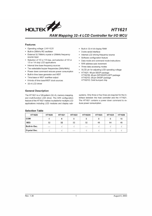
ht1621中文资料_数据手册_参数
Halogen-Free Flame~Retardant Rigid Polyurethane Foams;
Halogen-Free Flame-Retardant Rigid Polyurethane Foams: Effect of Alumina Trihydrate and Triphenylphosphate on the Properties of Polyurethane FoamsM.Thirumal,1Nikhil K.Singha,1Dipak Khastgir,1B.S.Manjunath,2Y.P.Naik21Rubber Technology Centre,Indian Institute of Technology,Kharagpur721302,India2Bhaba Atomic Research Centre,Trombay,Mumbai400085,IndiaReceived25March2009;accepted20October2009DOI10.1002/app.31626Published online14January2010in Wiley InterScience().ABSTRACT:Rigid polyurethane foam(PUF)filled with mixture of alumina trihydrate(ATH)and triphenyl phos-phate(TPP)as fire retardant additive was prepared with water as a blowing agent.In this study,the ATH content was varied from10to100parts per hundred polyol by weight(php),and TPP was used at a higher loading of ATH(75and100php)in a ratio of1:5to enhance the processing during PUF preparation.The effects of ATH on properties such as density,compressive strength,morpho-logical,thermal conductivity,thermal stability,flame-re-tardant(FR)behavior,and smoke characteristics were studied.The density and compressive strength of the ATH-filled PUF decreased initially and then increased with further increase in ATH content.There was no signif-icant change in the thermal stability with increasing ATH loading.We determined the FR properties of these foam samples by measuring the limiting oxygen index(LOI), smoke density,rate of burning,and char yield.The addi-tion of ATH with TPP to PUF significantly decreased the flame-spread rate and increased LOI.The addition of TPP resulted in easy processing and also improved FR charac-teristics of the foam.V C2010Wiley Periodicals,Inc.J Appl Polym Sci116:2260–2268,2010Key words:fillers;flame retardance;polyurethanes;thermo-gravimetric analysis(TGA);alumina trihydrate(ATH)INTRODUCTIONRigid polyurethane foams(PUFs)are widely used as thermal insulators and mechanical shock absorbers in transport overpacks and in air conditioning.They are also used as structural materials because of their light weight,greater strength to weight ratio,and energy-absorbing capabilities.1PUF,like other organic polymeric materials,tends to be flammable. Thus,the flammability of PUF has long been a factor limiting its use.To improve the flame-retardance properties,different flame retardants(FRs)are added to PUF.However,some of the FR additives used in PUF adversely affect its physical properties and pollute the environment by the evolution of undesirable gases on burning.In recent years, because of the stringent safety standards,both pub-lic and environmental,set by statutory authorities across the world,it has become imperative to de-velop better FR materials with improved FR effi-ciency that are economical and,at the same time, halogen free.2In general,alumina trihydrate(ATH)is unique in having a high proportion($34%)of water and is used as an FR additive and smoke-suppressant filler. Such inorganic fillers are assuming increasing im-portance in the industry because of their desirable combination of low cost,low smoke,and relatively high fire-retardant efficiency.ATH decomposes at about220 C to form Al2O3and water:Al2O3Á3H2OÀ!D Al2O3þ3H2OThe effectiveness of ATH as an FR additive depends primarily on its endothermic decomposi-tion,which withdraws heat from the substrate and, hence,retards the rate of flame propagation.Water vapor also reduces oxygen supply as it expands and envelops the interface boundary of foam and the environment.The expanding water vapor also cools the surface effectively because it takes away the ma-jority of heat supplied to the foam because of its high heat-carrying capacity at high temperatures.In contrast to the antimony oxide/halogenated fire-re-tardant system,ATH can provide equivalent fire retardancy at a lower cost and with significantly reduced emission of gases of low toxicity and corro-sivity on exposure to a flame environment.3One of the major drawbacks of adding these fillers is that the mechanical properties become inferiorCorrespondence to:N.K.Singha(nks@rtc.iitkgp.ernet.in). Contract grant sponsor:Board of Research in Nuclear Sciences(BRNS),Mumbai,India.Journal of Applied Polymer Science,Vol.116,2260–2268(2010) V C2010Wiley Periodicals,Inc.compared to the bare foam samples.This is possibly due to insufficient interactions between the polymer and the filler,which result in their inferior proper-ties.Bonding interactions between the foam and the FR additives may be improved by various techni-ques.The surface of the filler can be treated with various species that act as compatibilizers or sur-face-active agents.In general,ATH is surface-treated with chemicals,such as carboxylic acids,silanes, zirconates,and titanates,to improve its dispersion and distribution within the polymer ually, the content of ATH in the formulation is very high(>50%).ATH is used as an FR material in preparing FR rubber products(e.g.,cables,conveyor belts)and in plastic materials.4–13There have been reports of the use of ATH in polyurethane elastomers14,15and flexible16–19and rigid PUFs20–23as a low-cost FR and smoke-suppressant additive.In this investigation,we report the use of ATH as an FR nonreactive additive in the preparation of rigid PUF and the effects of ATH on the mechanical properties,thermal conductivity,thermal stability, FR,and smoke-density properties.At higher load-ings of ATH,the processing and preparation of PUFs were very difficult because of the resultant high viscosity.Therefore,at higher loadings of ATH, triphenyl phosphate(TPP)was used as a viscosity-suppressant and to improve the flame-resistant properties.EXPERIMENTALMaterialsPolymeric methane diphenyl diisocyanate(PMDI; NCO¼30.8%and functionality¼ 2.7)and poly (ether polyol)(OH content¼440mg of KOH/g,av-erage functionality¼ 3.0)were obtained from Huntsman International Pvt.,Ltd.(Mumbai,India). Distilled water was generated in our laboratory and was used as a chemical blowing agent.N,N,N0,N0,N0-Pen-tamethyldiethylenetriamine(PMDETA),obtained from Aldrich(St.Louis,MO),was used as a catalyst.Poly-ether dimethyl siloxane(TEGOSTAB B8460)supplied by Goldschmidt(Essen,Germany)was used as a surfac-tant.ATH,with a density of2.42g/cm3and an average particle size of200l m,and TPP,supplied by Phoenix Yule,Ltd.(Kolkata,India),were used as FR additives. All of the chemicals were used as received. Preparation of the foamATH-and TPP-filled PUF samples were prepared by a one-shot and free-rise method.The chemical com-positions of different filled foams are shown in Table I.Except for PMDI,all of the raw materials were well mixed in a plastic beaker,and then,FR was added,and the resulting mixture was thoroughly mixed with the help of a high-speed mechanical stirrer (3000rpm).Finally,PMDI was added to the mixture for a short duration with vigorous stirring for10s. The final resulting mixture was immediately poured into an open mold(30Â25Â15cm3)to produce free-rise foams.After preparation,the foam sample was kept in an oven at70 C for24h to complete the polymerization reaction.Different test samples were cut into specific foam shapes after curing.The sam-ples were rubbed with fine emery paper to get the proper dimensions.Different properties of the foams were analyzed with ASTM standard test methods. The amount of PMDI required for the reaction with polyether polyol and distilled water was calculated from their equivalent weight.For the completion of the reaction,excess PMDI(NCO/OH¼ 1.1)was used.Similarly,all foam samples were prepared by adjustment of the ATH content relative to polyol. Measurement of different propertiesMechanical propertiesThe apparent density of the PUF samples was meas-ured as per ASTM D1622-03;the average value of three samples is reported.The mechanical properties of the PUF samples were measured under ambient conditions with an Instron universal testing machine Hounsfield testing equipment(model H10KS).The compressive stress at10%strain in the parallel-to-foam rise direction was performed according to ASTM D1621-00.The size of the specimen was55Â55Â30mm3(LengthÂWidthÂThickness),the rate of crosshead movement was fixed at2.5mm/ min for each sample and the load cell used was 10kN.The strengths of five specimens per sample were measured,and the average of these values is reported.Scanning electron microscopy(SEM)analysisThe morphology of the PUF samples was studied with a scanning electron microscope(JEOL,JSM 5800,Tokyo,Japan).The samples were gold-coatedTABLE IChemical Composition of ATH/TPP-Filled Water-BlownRigid PUFMaterial php Polyether polyol100.0 PMDETA0.5 Tegostab B8460 2.0 Distilled water0.3 ATH10–50,75,100 TPP10,15,20 PMDI122.0RIGID POLYURETHANE FOAMS2261Journal of Applied Polymer Science DOI10.1002/appbefore scanning to provide an electrically conductive surface.An accelerating voltage of20kV was used while we recorded the scanning electron micrograms. Thermal conductivity testThe thermal conductivity of the PUFs was tested within a week of preparation of the PUFs with a guarded hot plate thermal conductivity meter as per ASTM C177-97.The size of the specimen was100Â100Â25mm3(LengthÂWidthÂThickness). Thermogravimetry(TG)studyThe decomposition temperature and char residue of the foams were analyzed on a TG analyzer Q50(TAInstruments,New Castle,DE)under a nitrogen envi-ronment at a heating rate of20 C/min over the tem-perature range30–800 C.Limiting oxygen index(LOI)testThe flammability test was performed with an LOI test instrument(Stanton Redcroft FTA unit,East Grinstead,UK)as per ASTM D2863-97.The speci-mens for the LOI measurement were120Â12Â12 mm3(LengthÂWidthÂThickness),five specimens per sample were measured,and their average values are reported.Test for flame propagationThe rate of flame spread was measured as per Fed-eral Motor Vehicle Safety Standard302.24A PUF specimen with dimensions of150Â10Â10mm3 (LengthÂWidthÂThickness)was exposed hori-zontally at its one end to a small flame for15s.The distance and time of burning or the time to burn between two specific marks were measured.The burn rate was expressed as the rate of flame spread according to the following formula:B¼60(L/T), where B,L,and T are the burn rate(mm/min), length of the flame travels(mm),and time(s)for the flame to travel L mm,respectively.Three specimens per sample were measured,and their average values are reported.Smoke-density testThe smoke density was measured with a smoke-density chamber(made by S.C.Dey and Co.,Kol-kata,India)as per ASTM D2843-04.The smoke gen-erated(flaming mode)in the process of burning the sample was measured by the change in light inten-sity.The size of the PUF specimen was100Â100Â12mm3(LengthÂWidthÂThickness).The maxi-mum smoke density was measured as the highest point of the light absorption versus time curve.This smoke-density rating represented the total amount of smoke present in the chamber for the4-min time and was measured with the following equation:Smoke-density rating¼A=TÂ100where A and T are the area under the light absorp-tion versus time curve and the total area of the curve,respectively.Determination of the char yields(CYs)We measured the CYs of the foams by heating the PUF in a muffle furnace at550 C for30min.The CY was calculated with the following equation:CY¼W b/W oÂ100,where W b and W o are the weights of the sample after and before burning.RESULTS AND DISCUSSIONDensityFoam density is a very important parameter that affects the mechanical properties of PUFs.25In gen-eral,the foam density is dependent on the degree of foaming,which in turn,depends in part on the type and amount of blowing agent.In this study,the amount of chemical blowing agent(distilled water) was kept constant.Table II shows the density of PUFs filled with ATH at different concentrations.It indicates that the density decreased with the addi-tion of small quantities of ATH-filled PUF and then increased with further increase in ATH loading.The density decreased at an initial loading of ATH.This was due to the increase in the cell size,as shown in the SEM figures(discussed later).However,beyond 20parts per hundred polyol by weight(php)of ATH loading,the density linearly increased with increasing ATH loading.This was due to a decreaseTABLE IIEffect of ATH/TPP on the Density and CompressiveStrength of PUFATHloading(php)TPPloading(php)Density(kg/m3)Compressivestrengthat10%strain(kg/cm2)Reducedcompressivestrength[MPa/(g/cm3)] 001038.17.910—88 5.5 6.320—81 5.0 6.230—13110.58.040—14011.38.150—15313.08.5501095 4.1 4.3751516514.48.7 1002020718.89.12262THIRUMAL ET AL. Journal of Applied Polymer Science DOI10.1002/appin the cell size and to the higher density of ATH (2420kg/m3)than that of neat PUF.The density of PUF filled with ATH(50php)and TPP(10php) was much lower than that of the PUF filled with ATH(50php)alone.This was because of the dilut-ing effect of TPP.However,with increasing ATH content,the density increased further(Table II).This was because the volume of PUF decreased after expansion as the amount of ATH increased,22which led to a greater amount of solid material(poly-urethane and ATH)instead of gaseous phase. Mechanical propertiesThe mechanical properties of PUF are important pa-rameters that determine its applications,such as in load bearing and as packaging materials.To study the effect of ATH loading on the compressive prop-erties of PUFs,the effect of foam density and the compressive strength of different foams were nor-malized by division by their respective densities.Ta-ble II shows the effects on the reduced compressive strength and compressive strength at10%strain of the PUFs filled with increasing loading of ATH and TPP.The table indicates that the reduced compres-sive strength and compressive strength at10%strain of PUFs filled with ATH initially decreased and then increased with further increases in the ATH loading. The initial decrease in properties was due to an increase in the average cell size of the PUFs,which also resulted in a decrease in the density.A higher loading of ATH caused a positive effect on the me-chanical properties of the PUFs.This was due to an increase in the cell wall thickness and also an increase in the density.It is known that the degree of foaming of PUFs depends on the viscosity and surface tension of the particular formulation.26 Higher loadings of ATH resulted in an increase in the viscosity(2Pa s for20php ATH from1.1Pa s for polyol),and this led to a decrease in the blowing or expansion of the PUFs.The mechanical properties of PUF filled with ATH(50php)and10php TPP decreased drastically compared to those of the PUF filled with only50php ATH.This decrease in the mechanical properties was due to the plasticizing effect of TPP with ATH,which was consistent with the change in density,as shown in Table II.In gen-eral,the metallic hydroxide of mineral fillers,such as ATH and magnesium hydroxide,act as nonrein-forcing fillers,because of its poor wetting or adhe-sion with the polymer matrix,and also,with inclu-sion of higher amounts,leads to agglomeration because the filler–filler interaction becomes more pronounced.Pinto et al.14observed poor mechanical properties in a polyurethane elastomer filled with ATH.In this case,the mechanical properties of PUF decreased at the initial loading of ATH,but they increased at higher loadings of ATH.This was due to an increase in the cell wall thickness.The interfa-cial contact between the polyurethane matrix and ATH modified at its surface improved the polymer–filler interaction and filler dispersion.This resulted in improved mechanical properties in the rigid PUF. Anorga et al.16also reported improved physical properties in flexible PUFs with the addition of ATH. MorphologyIn general,the physical properties of foam not only depend on the rigidity of the polymer matrix but also on the cellular structure of the foam.The mor-phology of a rigid PUF sample was studied with SEM.Figure1(a–d)shows the morphology of PUFs filled with ATH and TPP at different loadings.The shapes of the cells in the neat PUF and in the ATH-filled PUF were approximately spherical.As shown in Figure1(b),the average cell size of the PUF became bigger with the incorporation of lower amounts of ATH compared to the neat PUF[Fig. 1(a)].This was because ATH did not locate in the cell struts but between the cell walls.This caused an in-homogeneous cellular structure,which was responsi-ble for the lower compressive strength.26However, at higher loading of ATH(40php),the average cell size of PUF decreased because of less blowing[Fig. 1(c)].This may be due to the addition of a higher amount of ATH,which resulted in an increase in the viscosity(e.g.,2Pa s for20php ATH-filled polyol from1.1Pa s for polyol without ATH)of the foam formulation.The increased viscosity of the mixture led to a lower blowing tendency.Also,the morphol-ogy of the PUF was not very homogeneous because of the nonhomogeneous dispersion of ATH.The effi-ciency of foaming of PUF depends on the viscosity and surface tension of a particular formulation.27 Simioni et al.22also observed a decrease in average cell size with the addition of ATH(100php)in PUF. They found that the amount of polymer was drawn into the cell struts by the filler granules and also con-firmed the absence of interaction between the poly-mer and the filler.In this case,the addition of TPP to the PUF filled with a higher loading of ATH decreased the viscosity.For example,the viscosity of polyol filled with20php ATH was2Pa s;when TPP (4php)was added to this system,the viscosity dropped to1.6Pa s,which was due to the plasticiz-ing effect of TPP.This decrease in viscosity led to a good blowing efficiency,and thus,it increased the cell size[Fig.1(d)].Thermal conductivityThe thermal conductivity of PUF depends on the av-erage cell size,foam density,cell orientation,ratio ofRIGID POLYURETHANE FOAMS2263Journal of Applied Polymer Science DOI10.1002/appclosed-to open-cell content,and thermal conductiv-ity of filling materials.28Figure 2shows the effect of ATH and TPP on the thermal conductivity of the PUFs.The table indicates that the thermal conductiv-ity of PUF increased with increasing ATH loading.This was due to the high viscosity of the PUF for-mulation,which increased with increasing ATH loading and led to a nonhomogeneous dispersion of ATH.Therefore,the cellular structure of PUF was not very fine,and the bigger the average cell size was,the more the thermal conductivity increased.In addition,because of the greater volume of solid con-tent (polyurethane and ATH)in the ATH-filled PUF,there was a greater contribution to the thermal con-ductivity of PUF.Simioni et al.22also observed an increase in thermal conductivity with increasing ATH loading with PUFs.At the higher loading of ATH (along with TPP),PUF showed a decrease in the thermal conductivity;this was due to a decrease in the average cell size and an increase in the den-sity.It is well known that the cell size of a PUF depends on the viscosity and surface tension of the mixture.In this study,an increase in viscosity at higher loadings of ATH led to a reduction in the cell size.Thermal analysisFigure 3shows the TG/differential thermogravime-try (DTG)thermograms of ATH and TPP FR addi-tives under a nitrogen atmosphere.The figure reveals that the weight loss of ATH took place in three different temperature ranges,at 273,353,andabout 516 C,and their corresponding weight losses were about 1.2,20.5,and 32.2%,respectively.These weight losses were due to the removal of chemically bound water present in the ATH as shown:Al 2O 3Á3H 2OÀ!270À350C À2H 2OAl 2O 3ÁH 2O À!515CÀH 2OAl 2O 3This result was in good agreement with the resultsreported by Simioni and Modesti.23The onset tem-perature (temperature at 5%weight loss)of ATH was 303 C,which was higher than that of TPP (274 C).This indicated that the thermal stabilityofFigure 1Microphotographs of the ATH/TPP-filled PUF samples:(a)neat,(b)20php ATH,(c)40php ATH,(d)75php ATH þ15phpTPP.TPP was lower than that of ATH.The degradation pattern of TPP indicated that the TPP degraded completely to volatiles by 364 C and left no char res-idue.However,in the case of ATH,the weight loss was slow at the same temperature.The maximum degradation temperature (T max )of TPP was 356 C and was observed in a single step.The amount of residue (CY)of ATH was greater (67%)than that of TPP,which was almost zero at 550 C.Figure 4demonstrates the TG/DTG curves of PUF filled with and without ATH and ATH/TPP.In the neat and filled foam samples,the thermal degrada-tion took place in the range 250–420 C.The DTG curves of the PUFs filled with ATH and ATH/TPP showed a shoulder peak,which was probably due to the elimination of surface-active compounds used in ATH to improve its dispersion in the polymer matrix.With addition of TPP into the ATH,the weight loss of the samples was greater.T max for theneat and filled PUFs occurred at about 350 C,but CY was greater in case of filled PUFs compared to neat PUF.However,CY of the PUFs decreased with the addition of TPP into the ATH-filled PUF,as expected from the thermogravimetric analysis (TGA)curve of TPP (Fig.3,which shows no CY).This was probably due to the gas-phase mechanism of phos-phate additives.Different other phosphates,for example,ammonium polyphosphate (APP),have shown higher CYs because of the condensed-phase mechanism.29Table III shows the T max and CY values at 700 C of the PUFs filled with ATH and TPP under a nitro-gen atmosphere.There was no significant change in T max of PUF with ATH.Simioni and Modesti 23also found that ATH did not modify the TGA curves of their PUFs.In general,the degradation temperature of a polymer should increase with ATH loading.This is due to the endothermic decomposition of ATH,which decreases the temperature in the sur-roundings of the materials.Moreover,the water dilution and the formation of an aluminum oxide protective layer decrease the combustible gases and also act as barrier for transport of oxygen and fuel into polymer.Nachtigall et al.30observed an increase in the degradation temperature of modified PP on loading with ATH.In our case,there was no signifi-cant change in T max of the PUFs with or without the addition of ATH.This was probably due to the reac-tions between the water molecules released from ATH and the polyurethane degradation products (e.g.,isocyanate,carbodiimide),which were exother-mic in nature.The CY of ATH filled PUF increased with increasing ATH loading.However,the combi-nation of ATH with TPP decreased CY slightly,which might have been due to the gas-phase mecha-nism of TPP.In general,the addition of phosphate (APP)additives leads to the condensed-phase mech-anism of fire retardation.29Thus,it decreases the thermal degradation temperature of the polymer,which results in a greater quantity of CY.However,some phosphorus compounds may also be active in the gas phase by a radical trapping mechanism.In this case,TPP acted as gas phasemechanism,TABLE IIIEffect of ATH/TPP on T max of PUFSample ATH loading (php)TPP loading (php)T max in N 2( C)CY in TGA at 700 C under N 2(%)100361.710.5210—361.417.3330—362.318.9450—360.220.855010364.219.3610020361.417.3RIGID POLYURETHANE FOAMS 2265Journal of Applied Polymer Science DOI 10.1002/appthereby decreasing CY of the PUF filled with ATH/ TPP compared to the same with ATH alone.FR behaviorWe analyzed the FR behavior of PUFs filled with ATH and TPP at different loadings by determining the LOI,rate of flame spread,smoke density,and CY measurements.Table IV shows the effect of ATH on the LOI of PUF.It clearly shows that the LOI value slightly increased from22to25%with the addition of ATH in PUF.This lesser beneficial effect of ATH on the flame retardation of PUF occurred, because the initial water elimination process of ATH was hampered,as discussed in Thermal Analysis section.It may also have been due to the fact that lower amounts of ATH in the PUFs protected the dehydrating effect of ATH.An endothermic effect is only effective in PUFs having a higher amount of ATH.23The fact that the ATH did contain bound water is very important for its flame retardation in polymers.The slight increase in the LOI was due to the endothermic decomposition of ATH and water elimination from the third stage and also the forma-tion of aluminum oxide char on the surface of the polymer,which acted as an insulative protective layer.Table IV indicates that the LOI of PUF sample filled with50php ATH and10php TPP was higher than the PUF filled with same amount of ATH only. This was due to the volatilization of TPP and the formation of phosphorus acid at higher tempera-tures.The addition of APP improved the flame retardance of the polymers via the condensed-phase mechanism.In this case,APP first decomposed to produce polyphosphoric acid,which accelerated the formation of char via ester formation on reaction with hydroxyl precursor.29In this case,TPP first decomposed to form phosphorus acids(as shown in the following equation),which reacted with the A OH-containing moiety formed on the depolycon-densation of PUF at higher temperatures:31ðPhOÞ3P¼¼OÀ!D PhOHþH3PO4þH3PO3For a combination of additive systems,the numer-ical values of LOI may be shifted from those of the theoretically calculated ones.The upward shift is called synergism,and the downward shift is known as antagonism.The theoretical LOI values of the flame-retarded PUFs filled with ATH/TPP were cal-culated from knowledge of their experimental values under identical conditions with the individual addi-tives and without additive.For instance,the LOI val-ues of a polymer with binary combinations(LOI ab) can be calculated from the following equation:LOI ab¼LOI aþLOI bÀLOI cwhere LOI a,LOI b,and LOI c are the LOI values for samples containing‘‘a’’additive,‘‘b’’additive,and without additives,respectively.32According to the previous relationship,the experimental value of LOI of the ATH/TPP filled PUFs was greater(27.2%) than the theoretical value of LOI(26.2%).Hence,the PUFs filled with these combinations of additives showed synergistic behavior.The mechanism for this behavior may have been due to the combination of gas-phase(volatilization of TPP)and condensed-phase mechanisms of TPP and ATH.Simioni and Modesti23also found beneficial behaviors of fire retardants and easy processing of higher loaded ATH and dimethyl methyl phosphonate(DMMP) fire-retardant additives in PUF.Table IV shows the effect of ATH in the presence of TPP on the rate of flame spread of PUF at room temperature.The rate of flame spread or the rate ofTABLE IVEffect of ATH/TPP on LOI,Smoke Density,Rate of Flame Spread,and CYof the PUFSampleATHloading(php)TPPloading(php)LOI(%)Maximumsmokedensity(%)Smokedensityrating(%)Flamespread rate(mm/min)CY in the mufflefurnace at550 Cfor30min(%)1Neat—22.063622000.05210—22.2——182 3.2320—22.55451150 6.0430—23.0——11312.2540—23.7——10313.4650—25.045309417.37—1023.2——158 1.38501027.254368812.49751528.06461SE a18.2101002029.5——NB b26.0a Self-extinguished after15s.b Not burning(did not catch fire).2266THIRUMAL ET AL. Journal of Applied Polymer Science DOI10.1002/app。
莫贾V2416A系列迷你型无风扇、振动防护计算机产品介绍说明书

V2416A SeriesCompact,fanless,vibration-proof computers for rolling stock applicationsFeatures and Benefits•Intel Celeron/Core i7processor•Two hot-swappable2.5-inch HDD or SSD storage expansion trays•Dual independent DVI-I displays•2Gigabit Ethernet ports with M12X-coded connectors•2CFast sockets for OS backup•M12A-coded power connector•Compliant with EN50121-4•Complies with all EN50155mandatory test items1•IEC61373certified for shock and vibration resistance•Ready-to-run Debian7,Windows Embedded Standard7,and Windows10Embedded IoT Enterprise2016LTSB platforms•-40to70°C wide-temperature models available•Supports SNMP-based system configuration,control,and monitoring(Windows only)CertificationsIntroductionThe V2416A Series embedded computers are based on the Intel3rd Gen processor and feature4RS-232/422/485serial ports,dual LAN ports,and 3USB2.0hosts.In addition,the V2416A computers provide dual DVI-I outputs and comply with the mandatory test items of the EN50155 standard,making them suitable for a variety of industrial applications.The CFast socket,SATA connectors,and USB sockets provide the V2416A computers with the reliability needed for industrial applications that require data buffering and storage expansion.Most importantly,the V2416A computers come with2hot-swappable storage trays for inserting additional storage media,such as hard disk or solid-state drives,and support hot swapping for convenient,fast,and easy storage replacement. Each storage tray has its own LED to indicate whether or not a storage module is plugged in.The V2416A Series computers come preinstalled with a choice of Linux Debian7or Windows Embedded Standard7to provide programmers with a familiar environment in which to develop sophisticated,bug-free application software at a low cost.1.This product is suitable for rolling stock railway applications,as defined by the EN50155standard.For a more detailed statement,click here:/doc/specs/EN_50155_Compliance.pdfAppearanceFront View Rear ViewSpecificationsComputerCPU V2416A-C2Series:Intel®Celeron®Processor1047UE(2M cache,1.40GHz)V2416A-C7Series:Intel®Core™i7-3517UE Processor(4M cache,up to2.80GHz) System Chipset Mobile Intel®HM65Express ChipsetGraphics Controller Intel®HD Graphics4000(integrated)System Memory Pre-installed4GB DDR3System Memory Slot SODIMM DDR3/DDR3L slot x1Supported OS Linux Debian7Windows Embedded Standard7(WS7E)32-bitWindows Embedded Standard7(WS7E)64-bitStorage Slot CFast slot x2Computer InterfaceEthernet Ports Auto-sensing10/100/1000Mbps ports(M12X-coded)x2Serial Ports RS-232/422/485ports x4,software selectable(DB9male)USB2.0USB2.0hosts x1,M12D-coded connectorUSB2.0hosts x2,type-A connectorsAudio Input/Output Line in x1,Line out x1,M12D-codedDigital Input DIs x6Digital Output DOs x2Video Input DVI-I x2,29-pin DVI-D connectors(female)Digital InputsIsolation3k VDCConnector Screw-fastened Euroblock terminalDry Contact On:short to GNDOff:openI/O Mode DISensor Type Dry contactWet Contact(NPN or PNP)Wet Contact(DI to COM)On:10to30VDCOff:0to3VDCDigital OutputsConnector Screw-fastened Euroblock terminalCurrent Rating200mA per channelI/O Type SinkVoltage24to40VDCLED IndicatorsSystem Power x1Storage x1Hot-swappable2LAN2per port(10/100/1000Mbps)Serial2per port(Tx,Rx)Serial InterfaceBaudrate50bps to921.6kbpsFlow Control RTS/CTS,XON/XOFF,ADDC®(automatic data direction control)for RS-485,RTSToggle(RS-232only)Isolation N/AParity None,Even,Odd,Space,MarkData Bits5,6,7,8Stop Bits1,1.5,2Serial SignalsRS-232TxD,RxD,RTS,CTS,DTR,DSR,DCD,GNDRS-422Tx+,Tx-,Rx+,Rx-,GNDRS-485-2w Data+,Data-,GNDRS-485-4w Tx+,Tx-,Rx+,Rx-,GNDPower ParametersInput Voltage12to48VDCPower Connector M12A-coded male connectorPower Consumption(Max.) 3.3A@12VDC0.82A@48VDCPower Consumption40W(max.)Physical CharacteristicsHousing AluminumIP Rating IP30Dimensions(with ears)250x86x154mm(9.84x3.38x6.06in)Dimensions(without ears)275x92x154mm(10.83x3.62x6.06in)Weight4,000g(8.98lb)Installation DIN-rail mounting(optional),Wall mounting(standard) Protection-CT models:PCB conformal coating Environmental LimitsOperating Temperature Standard Models:-25to55°C(-13to131°F)Wide Temp.Models:-40to70°C(-40to158°F) Storage Temperature(package included)-40to85°C(-40to185°F)Ambient Relative Humidity5to95%(non-condensing)Standards and CertificationsEMC EN55032/24EMI CISPR32,FCC Part15B Class AEMS IEC61000-4-2ESD:Contact:6kV;Air:8kVIEC61000-4-3RS:80MHz to1GHz:20V/mIEC61000-4-4EFT:Power:2kV;Signal:2kVIEC61000-4-5Surge:Power:2kVIEC61000-4-6CS:10VIEC61000-4-8PFMFRailway EN50121-4,IEC60571Railway Fire Protection EN45545-2Safety EN60950-1,IEC60950-1Shock IEC60068-2-27,IEC61373,EN50155Vibration IEC60068-2-64,IEC61373,EN50155DeclarationGreen Product RoHS,CRoHS,WEEEMTBFTime332,173hrsStandards Telcordia(Bellcore),GBWarrantyWarranty Period3yearsDetails See /warrantyPackage ContentsDevice1x V2416A Series computerInstallation Kit8x screw,for storage installation2x storage key1x wall-mounting kit8x washer,for HDD/SSDDocumentation1x document and software CD1x quick installation guide1x warranty cardDimensionsOrdering InformationModel Name CPU Memory(Default)OS CFast(CTO)Backup CFast(CTO)Hot-SwappableSSD/HDD Tray(CTO)Operating Temp.ConformalCoatingV2416A-C2Celeron1047UE4GB or optional1(Optional)1(Optional)2(Optional)-25to55°C–V2416A-C2-T Celeron1047UE4GB or optional1(Optional)1(Optional)2(Optional)-40to70°C–V2416A-C2-CT-T Celeron1047UE4GB or optional1(Optional)1(Optional)2(Optional)-40to70°C✓V2416A-C7i7-3517UE4GB or optional1(Optional)1(Optional)2(Optional)-25to55°C–V2416A-C7-T i7-3517UE4GB or optional1(Optional)1(Optional)2(Optional)-40to70°C–V2416A-C7-CT-T i7-3517UE4GB or optional1(Optional)1(Optional)2(Optional)-40to70°C✓V2416A-C2-W7E Celeron1047UE4GB8GB1(Optional)2(Optional)-25to55°C–V2416A-C2-T-W7E Celeron1047UE4GB8GB1(Optional)2(Optional)-40to70°C–V2416A-C7-T-W7E Core i7-3517UE4GB8GB1(Optional)2(Optional)-40to70°C–Accessories(sold separately)Battery KitsRTC Battery Kit Lithium battery with built-in connectorCablesCBL-M12XMM8PRJ45-BK-100-IP67M12-to-RJ45Cat-5E UTP gigabit Ethernet cable,8-pin X-coded male connector,IP67,1mCBL-M12(FF5P)/Open-100IP67A-coded M12-to-5-pin power cable,IP67-rated5-pin female M12connector,1mConnectorsM12A-5PMM-IP685-pin male circular threaded D-coded M12USB connector,IP68M12X-8PMM-IP678-pin male X-coded circular threaded gigabit Ethernet connector,IP67M12A-5P-IP68A-coded screw-in sensor connector,female,IP68,4.05cmM12A-8PMM-IP678-pin male circular threaded A-codes M12connector,IP67-rated(for field-installation)Power AdaptersPWR-24270-DT-S1Power adapter,input voltage90to264VAC,output voltage24V with2.5A DC loadPower CordsPWC-C7AU-2B-183Power cord with Australian(AU)plug,2.5A/250V,1.83mPWC-C7CN-2B-183Power cord with two-prong China(CN)plug,1.83mPWC-C7EU-2B-183Power cord with Continental Europe(EU)plug,2.5A/250V,1.83mPWC-C7UK-2B-183Power cord with United Kingdom(UK)plug,2.5A/250V,1.83mPWC-C7US-2B-183Power cord with United States(US)plug,10A/125V,1.83mAntennasANT-WDB-ANF-0407 2.4/5GHz,omni-directional antenna,4/7dBi,N-type(male)Wall-Mounting KitsV2400Isolated Wall Mount Kit Wall-mounting kit with isolation protection,2wall-mounting brackets,4screwsDIN-Rail Mounting KitsDK-DC50131DIN-rail mounting kit,6screws©Moxa Inc.All rights reserved.Updated Jun12,2019.This document and any portion thereof may not be reproduced or used in any manner whatsoever without the express written permission of Moxa Inc.Product specifications subject to change without notice.Visit our website for the most up-to-date product information.。
信维AMD推出全新Magny-Cours平台主板KGPE—D16

口) 、板 载 3网卡 以 及 可 进 行 远 程 管 理 的华 硕 AS 4 i MB ~KVM 模 块 .有效 提 升 系统 平 台 的 可 管 理 性 ,降 低 了 搭 建 成 本 。总 体 来 说 , 维 国 际 旗 下 代 理 的 这 信
华 硕 KGP E-D1 6为 1 x 3英 寸 标 21 准 E B规 格 主 板 。 用 AMD R5 9 + E 采 S 60 S 50 P 1 0芯 片组 , 供 两 个 S c e 4处 提 o k tG3
主板 可 以 满 足 此 类 需要 。我们 很 高 兴 地
《 计算祝 与J 》2 1 回络 0 0年第 0 期 8
x 6 + 2 CI E x (/IO ,
高 的 性 能 级 别 ,而 KGP D1 E— 6服 务 器
硕 MI 声 卡 或 PK D 存 储 卡 扩 O I E RAI
展 。 数 据 存 储 方 面 ,该 产 品 板 载 的
华 硕 KGP E-D1 6
13 3 3RDI MM 四 通 道 内 存 。 足 高 负 荷 满 运 算 状 态 下 系统 对 内 存 的极 端 需 求 。
器 ,用 户 可 通 过 该 产 品 搭 建 2 4核 的强
大平 台 。
AS US 服 务 器 业 务 部 门 总 经 理 To Ln 表 示 : 基 于 ^MD R 9 / m i “ S 56 O s 5o P 1 o芯 片 组 的 AS US KGP E-D1 6可 搭 载 AMD 皓龙 6 0 1 0系 列 处 理 器 , 处 在 理 大 量 实 际 的 负 载 时 表 现 出 高 效 的 性 能 。对 于 需 要 使 用 W e -a ig服 务 器 b fcn 的企 业和 机 构 , 常 要 求 服 务 器 提 供 极 通
ht1621中文资料
SD0432 中集成了一个简单的声音发生器,此发声器可输出一对不同的驱动信号至 BZ 和 BZ 以产生单音,执 行 TONE 4K 与 TONE 2K 命令,可选择两个不现的音频输出,即 4KHZ 与 2KHZ 这两个频率,TONE ON 及 TONE OFF 命令可打开或关闭语音输出,语音输出 BZ 和 BZ,是一对不同的带驱动蜂鸣器。当系统关闭或语音输出被禁止时, BZ 及 BZ 将处于低电平状态。
命令 LCD OFF 是通过关闭 LCD 偏压发生器来关闭 LCD 显示器。反之,LCD ON 则启动 LCD 显示。BIAS COM 是与
LCD 屏面相关命令。使用 LCD 相关命令,SD0432 可与绝大多数类型的 LCD 屏面兼容。
3. 6 命令格式
SD0432 可由 S/W 设置来配置。有两种命令模式分别用来配置 SD0432 和传送 LCD 显示数据。配置 SD0432 的命
令模式(普通模式)识别码为 100,此命令模式由系统配置命令、LCD 配置命令、音频选择命令、定时器/看门狗
定时器设置命令及操作命令组成。另一方面,数据模式包括 READ、WRITE 及 READ-MODIFY-WRITE 操作。下表为数
据模式及命令模式识别码:
com 操
作
. READ
s WRITE
le RAM 中的数据由 READ、WRITE 以及 READ-MODIFY-WRITE 指令进行存取,下图为由 RAM 控制 LCD 的映象图。
e SEG
COM
COM3
COM2
COM1
COM0
六位地址(A5,A4…A0)
. SEG0
0
ww SEG1
1
w SEG2
SW1621

DATA VSS OSCI OSCO VLCD VDD IRQ BZ、BZB COM0~COM3 SEG0~SEG31
I/O 串行数据输入/输出端(带上拉电阻) -- 电源地 I 用外部振荡时在两管脚间并联一个32.768KHz 晶振;如用片上内建 O RC振荡时,OSCI和OSCO应悬空。 I LCD电源输入 -- 电源正 O 时基或WDT定时器溢出标志,NMOS 开漏输出 O 蜂鸣器信号输出端 O LCD COM输出端 O LCD SEG输出端
32×4 段位式 LCD 驱动器
LCD Seg 3V
IOL3
灌电流 5V
LCD Seg 3V
IOH3
拉电流 5V
输入口 3V
RPH
上拉电阻 5V
AC电气特性
符号 fsys1 fsys2 Fsys3
参数 VDD 3V
系统时钟 1 5V 3V
系统时钟 2 5V 3V
系统时钟 3 5V
—
fLCD
LCD 时钟 —
V1.0
SW1621
32×4 段位式 LCD 驱动器
注:CS:片选信号
BZ,BZB:蜂鸣器输出
RD,WR,DATA:串行接口
COM0~COM3,SEG0~SEG31:LCD 驱动口 IRQ:时基/WDT时钟信号输出
产品一览表
系统资源
D01A24
产品型号
D01A28
SW1621
COM
4
4
4
SEG
14
CS,WR,RD,DATA
VOL=0.9V VOL=1.5V VOH=2.1V VOL=3.5V VOL=0.9V VOL=1.5V VOH=2.1V VOH=3.5V
intel c621a参数 -回复
intel c621a参数-回复Intel C621A是一款基于Intel定制的芯片组,广泛应用于高端服务器和工作站领域。
本文将逐步介绍Intel C621A的参数和特性。
Intel C621A是由Intel推出的一款高性能芯片组,支持多个处理器套件,包括Intel Xeon Scalable处理器和第二代Intel Xeon Scalable处理器。
该芯片组支持Intel QuickPath Interconnect(QPI)技术,提供高速的处理器互连。
它还支持DDR4内存,最多可扩展到6个通道和384GB 内存容量。
该芯片组还具有出色的I/O性能。
它支持高达10个PCI Express 3.0 x16总线,并支持4个SATA 3.0和10个USB 3.0接口,可以满足高带宽和高速数据传输的需求。
此外,Intel C621A还支持SAS 3.0和SATA Express存储接口,以满足大容量存储和高性能存储的要求。
在网络连接方面,Intel C621A提供了两个千兆以太网接口和两个10千兆以太网接口,以满足高速网络传输的需求。
此外,它还支持Intel Virtualization Technology(VT),可以提供强大的虚拟化能力。
与此外,Intel C621A还支持Intel Active Management Technology (AMT),提供远程管理和监视功能。
这使得IT管理员可以通过网络对远程服务器进行集中管理和监控,提高效率和灵活性。
总体而言,Intel C621A是一款功能强大的芯片组,适用于高端服务器和工作站。
它提供了出色的处理器互联、内存扩展和I/O性能,以及丰富的存储和网络接口。
此外,支持虚拟化和远程管理技术,进一步增强了可靠性和可管理性。
对于追求高性能、可靠性和灵活性的用户来说,IntelC621A是一个理想的选择。
在实际应用中,Intel C621A已经广泛用于需要高性能计算和大容量存储的场景。
dd-wrt固件支持的路由器型号
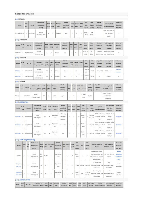
Pronghorn Metro SBC
-
?
Xscale IXP425@533
64
16
-
depends on card
4
1
?
1 LAN, 1 WAN
yes
17- 30 & 36- 60
CF socket, hw watchdog, temp. and volt. sensor
mini PCI
Serial port
JTAG port
Eth. port count
PoE
Volt. Input [V/A]
Special Features Notes
min required DD-WRT version
Notes for Running DD-WRT
Coyote
-
?
Xscale IXP425@533
v.24 sp2 - build 12646 - 13/08/09
MI424WR
MI424WR
C
LNQ802MAG
Xscale IXP425@533
32
8
depends on card
Atheros b/g
1
1
1
4 LAN 1 WAN
-
5V / 3A
OEM'd to Verizon, FIOS port will not work
clone ofdir-300
V24 RC5
[1]
AP431W
?
RRK-AP431W
Atheros AR2313A@180
16
4
Atheros
b/g
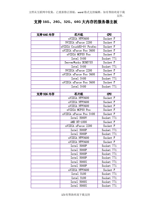
支持16G、24G、32G、64G大内存的服务器主板t
Socket F
微星5000V Master2-A6M
Intel 5000V
Socket 771
泰安S3970G2NR
AMD HT-1000
Socket F
华硕KFN4-DRE
nVIDIA nForce 2200
Socket F
Intel S5000PSLSATA
支持16G、24G、32G、64G大内存的服务器主板
Intel Socket 771接口处理器Amd Socket F(1207)接口处理器
支持64G内存
芯片组
CPU
技嘉GA-3CESL-RH
nVIDIA NFP3600
Socket F
华硕KFSN4-DRE
NVIDIA nForce 2200
Socket F
泰安S5397WAG2NRF
Intel 5400
Socket 771
泰安S2932WG2NR
nVIDIA nForce Pro 3600
Socket F
Intel S5400SF
Intel 5400
Socket 771
支持32G内存
芯片组
CPU
微星K9ND Speedster CA6
nVIDIA NFP3600
Socket F
微星K9ND Speedster WA6
nVIDIA NFP3600
Socket F
微星K9ND Speedster2 CA6
nVIDIA NFP3600
Socket F
技嘉GA-3CCWV-RH
nVIDIA MCP55 Pro
Socket F
微星K9NU Speedster CA6
信维AMD推出全新Magny-Cours平台主板KGPE-D16

理 器 , 连 接 64 T/ 三 .G sHT 总 线 , 产 品 还 了 提 供 1 该 6条
内 存 插 槽 , 高 支 持 2 6 B DD 3 3 RDI 最 5 G R3 1 3 . MM 四 通 道 内存 。 足 高负 荷运 算 状态 下 系统 对 内存 的极 端 需求 。 满 扩 充 方 面 ,华 硕 K P D1 G E— 6提 供 了 6条 扩 展 槽 , 包 括 l C 2 i 3 MHz和 5条 P I x P I 3 bt 3 / C —E插 槽 。 同 时 , 满 为 足 服 务 器 或 工 作 站 的 同 需 求 , 华 硕 K E- 6的 不 GP D1 P I E 插 槽 可 灵 活 配 置 为 2 C - 1 ( 显 卡 ) 1 C— xP I E x6 多 或 x P I E x 6 + 2 C — 8 I o 扩 展 ) 支 持 华 硕 MI C— l x P I E x (/ , O 声 卡 或 P K AI 存 储 卡 扩 展 。 数 据 存 储 方 面 , 产 品 IE R D 该 板 载 的 S 50 P 1 0南 桥 提 供 6个 S T G p 接 口 ,另 外 由 A A 3 bs P K AI 模 块 提 供 最 高 8个 S S硬 盘 接 口 。 足 用 户 IE R D A 满
Heg t) &W id wd ih ( , n o c,0,0, RCCOP ; S Y)
用价 值 。作 为 运 用 C OM 和 G S结 合 的 一 个 全 新 的 G S I I
软 件 技 术 体 系 的 具 体 实 践 , 未 来 态 势 图 显 示 发 展 的 方 是
向 之 一 , 业 界将 会得 到 迅速 而 广泛 的应 用 。 在
&Wid wd n o c, Ret e Wit cViw. dh0,Ret Jw. ih cV e Heg t 0 ) ; ,
运用思维导图记住高中英语3500之五----词根“按压挤”

词汇词根press:来自拉丁语的press词根,意为to press,表示按/压/挤。
1. press [pres]v. 压;按;逼迫;紧抱n. 压;按;新闻;出版社;印刷机【词根速记】press既是一个词根,又是一个单词,意为挤、压、按,引申出报刊、出版、印刷、新闻等含义。
★express [ɪk'spres] v. 表达adj. 迅速的;快递的 n. 快车,快递【词根速记】前缀ex-表示向外。
press, 压,推。
ex-press 即推出,表达、传达。
★expressive [ɪk'spresɪv] adj. 表现的;有表现力的;富于感情的;体现出某种感情(影响)的【词根速记】后缀-ive为形容词后缀,表示具有…性质的、有…特色的。
因此expressive表示表达能力强的、善于表达的。
【反】expressionless★expressly [ɪk'spreslɪ] adv. 清楚地,明显地;特别地,专门地【词根速记】-ly副词后缀。
ex-press-ly表示清楚地。
【同】specifically★expression [ɪkˈspreʃn] n. 表现,表示,表达;表情,脸色,态度,腔调,声调;式,符号;词句,语句,措辞,说法【词根速记】后缀-ion为名词后缀。
ex-press-ion即表达,表情。
★expressionism [ɪk'spreʃәnɪz(ә)m] n.〔绘画、文学或音乐的〕表现主义【词根速记】-ism名词后缀,表示宣扬某种理念、思想,含义翻译为…主义。
比如:capitalism(资本主义)、socialism(社会主义)、optimism(乐观主义)、pessimism (悲观主义)等。
Expressionism中的表现主义,指20世纪初流行于德国、法国、奥地利、北欧和俄罗斯的文学艺术流派。
主要特色是艺术家通过作品着重表现内心的情感,而忽视对描写对象形式的摹写,因此往往表现为对现实扭曲和抽象化来表达强烈的情感。
MASTERSPEC
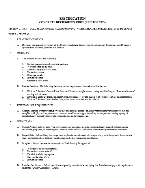
SPECIFICATIONCONCRETE DECK/GREEN ROOF (REINFORCED)SECTION 07123-A – COLD FLUID-APPLIED WATERPROOFING (WITH FA BRIC REINFORCEMENT) SYSTEM III PLUS PART 1 – GENERA L1.1RELATED DOCUMENTSA.Drawings and general provisions of the Contract, including General and Supplementary Conditions and Division 1Specification Sections, apply to this Section.1.2SUMMARYA.This Section includes the following:1.Surface preparation and substrate treatment.2.Waterproofing membrane.3.Sheet flashing and accessories.4.Protection course.5.Drainage panels.6.Insulation board.7.Geotextile filter fabric.B.Related Sections: The following Sections contain requirements that relate to this Section:1.Division 3 Section “Cast-in-Place Concrete” for concrete placement, curing, and finishing or “Pre-ca st Concrete”casting and placement.2.Division 5 Section “Expansion Joint Cover Assemblies”, for expansion-joint cover assemblies and installation.3.Division 7 Section “Joint Sealant” for joint sealant materials and installation.1.3PERFORMA NCE REQUIREMENTSA.General: Provide a waterproofing system that prevents the passage of liquid water under hydrostatic pressure andcomplies with physical requirements as demonstrated by testing performed by an independent testing agency ofmanufacturer’s current waterproofing formulations and system design.1.4SUBMITTALSA.Submit Product Data for each type of waterproofing specified, including manufacturer’s printed instructions forevaluating, preparing, and treating the substrate, technical data, and tested physical and performance properties.B.Project Data - Submit Shop Drawings showing locations and extent of waterproofing, including details for substratejoints and cracks, sheet flashing, penetrations, and other termination conditions.C.Samples – Submit representative samples of the following for approval:1.Waterproof membrane material.2.Protection course material.3.Prefabricated drainage panel.4.Geo-textile filter fabric.5.Insulation board.D.Installer Certificates – Submit certificates signed by manufacturer certifying that Installers comply with requirementsunder the “Quality Assurance” Article.1.5QUA LITY ASSURANCEA.Installer Qualifications: Engage an experienced Installer who is certified in writing and approved by waterproofingmanufacturer EPRO Services, Inc. for the installation of the SYSTEM III Plus Waterproofing System.B.Manufacturer Qualification: Obtain waterproofing materials and system components from a single manufacturer EPROServices, Inc.C.Field Sample: Apply waterproofing system field sample to 100 sq./ft. (9.3 s q./m.) of deck or wall to demonstrate surfacepreparation, joint and crack treatment, thickness, texture, and standard of workmanship.1.Notify Architect one week in advance of the dates and times when field sample will be prepared.2.If Architect determines that field sample, does not meet requirements; reapply waterproofing until field sample isapproved.3.Retain and maintain approved field sample during construction in an undisturbed condition as a standard forjudging the completed waterproofing. An undamaged field sample may become part of the completed Work.D.Pre-installation Conference: A pre-installation conference shall be held prior to application of the waterproofing systemto assure proper substrate and installation conditions, to include contractor, applicator, architect/engineer and specialinspector (if any).1.6DELIVERY, STORA GE, AND HA NDLINGA.Deliver materials to Project site as specified by manufacturer labeled with manufacturer’s name, product brand nameand type, date of manufacture, shelf life, and directions for storing and mixing with other components.B.Store materials as specified by the waterproofing manufacturer in a clean, dry, protected location and within thetemperature range required by waterproofing manufacturer. Protect stored materials from direct sunlight.C.Remove and replace material that cannot be applied within its stated shelf life.1.7PROJECT CONDITIONSA.Protect all adjacent areas not to be waterproofed. Where necessary, apply masking to prevent staining of surfaces toremain exposed wherever membrane abuts to other finish surfaces.B.Perform work only when existing and for-cast weather conditions are within manufacturer’s recommendations for thematerial and application method used.C.Minimum clearance of 24 inches is required for application of product. For areas with less than 24-inch clearance, theproduct may be applied by hand using ECOLINE-R.D.All plumbing, electrical, mechanical and structural items to be under or passing through the waterproof membrane shallbe positively secured in their proper positions and appropriately protected prior to membrane application.E.Waterproof membrane shall be installed before placement of reinforcing steel. When not possible, all exposedreinforcing steel shall be masked by General Contractor prior to membrane application.1.8WARRANTYA.General Warranty: The special warranty specified in this Article shall not deprive the Owner of other rights the Ownermay have under other provisions of the Contract Documents, and shall be in addition to, and run concurrent with, otherwarranties made by the Contractor under requirements of the Contract Documents.B.Special Warranty: Submit a written warranty signed by waterproofing manufacturer and Installer agreeing to repair orreplace waterproofing that does not meet requirements or that does not remain watertight within the specified warrantyperiod. Warranty does not include failure of waterproofing due to failure of substrate prepared and treated according torequirements or formation of new joints and cracks in substrate that exceed 1/16 inch (1.6 mm) in width.1.Warranty Period: 5-years after date of Substantial Completion.PART 2 – PRODUCTS2.1 MANUFA CTURERSA.SYSTEM III Plus; EPRO Services, Inc., Wichita, KS, 800-882-18961.Spray-Applied ECOLINE-S or roller-applied ECOLINE-R.2.Protection course ECOSHIELD-E10 or ECOSHIELD-E15.3.Drainage mat ECODRAIN-M20 (perforated) or ECODRAIN-S9000.2.2 WATERPROOFING MATERIALSA.Fluid applied waterproofing system – ECOLINE-S: a single course, high build, polymer modified, asphalt emulsion.Waterborne and spray applied at ambient temperatures. Non-toxic and odorless. ECOLINE-R has similar propertieswith greater viscosity and is roller or brush applied. Manufactured by EPRO Services, Inc.B.Fluid applied waterproofing physical properties.2.3 AUXILIARY MATERIALSA.Sheet Flashing: 60-mil reinforced modified asphalt sheet good with double-sided adhesive.B.Reinforcing Strip: Manufacturer’s recommended polypropylene and polyester fabric.C.Joint Detailing Sealant Mastic: ECOLINE-R, a high viscosity polymer modified water based asphalt material.1. Back Rod: Closed-cell polyethylene foam.2. Single component urethane sealant.2.4 PROTECTION COURSEA.Protection Course Usage-ECOSHIELD-E15B.ECOSHIELD physical properties.2.5 MOLDED-SHEET DRAINA GE PANELA.For extensive roof design.1.ECODRAIN-M20 a HDPE composite drainage panel, 3-diminsional, non-biodegradable with a permeable geo-textile heat bonded to drainage core.2.ECODRAIN-M20 Specification Table.B.For non-planting applications with free flow drainage.1.ECODRAIN-S9000, a polystyrene composite drainage panel, 3-diminsional, non-biodegradable with a permeablegeo-textile heat bonded to drainage core.2. ECODRAIN-S9000 Specification Table.2.6FILTER FA BRIC2.7 INSULATION BOARDPART 3 – EXECUTION3.1 EXAMINATIONA.Examine substrates, areas, and conditions under which waterproofing systems will be applied, with Installer present, forcompliance with requirements. Do not proceed with installation until unsatisfactory conditions have been corrected.3.2 SURFA CE PREPA RATIONA.Clean and prepare substrate according to manufacturer’s recommendations. Provide clean, dust-free, and dry substratefor waterproofing application.B.Mask off adjoining surfaces not receiving waterproofing to prevent spillage or over spray affecting other construction.C.Close off deck drains and other deck penetrations to prevent spillage and migration of waterproofing flu ids.D.Remove grease, oil, form release agents, paints, and other penetrating contaminants from concrete.E.Remove fins, ridges, and other projections and fill honeycomb, aggregate pockets, grout joints, tie holes, and othervoids with ECOLINE-R, hydraulic cement, or rapid-set grout.3.3 PREPARATION A ND TREATMENT AT TERMINATIONS AND PENETRATIONSA.Prepare vertical and horizontal surfaces at 90-degree terminations, at penetrations through waterproofing material, andat expansion joints, drains, and sleeves a ccording to ASTM C 898 and manufacturer’s recommendations.B.Apply two coats of ECOLINE-R (30 mil each) and embed a joint reinforcing strip in preparation coat and apply asecond coat over embedded joint reinforcing strip ensuring its complete saturation an d covering.1.Terminations should be treated 3 inches on each side for both vertical and horizontal.2.Penetrations should be treated in a 3 inch radius around penetration and 3 inches onto penetrating object.3.Penetrations should be additionally fastened with polypropylene zip tie or other suitable clamp.3.4 PREPARATIONS AND TREATMENT OF JOINTS AND CRA CKSA.Prepare, treat, rout, and fill joints and cracks in substrate according to ASTM C 898 and waterproofing manufacturer’srecommendations. Remove dust and dirt from joints and cracks complying with ASTM D 4258 prior to coatingsurfaces.B.Less than 1/16 in. - Apply two coats of ECOLINE-R waterproofing, 6 inches on each side of joint or crack and embed ajoint reinforcing strip in preparation coat and apply a second coat over embedded joint reinforcing strip ensuring tocomplete saturation and covering.C.Greater then 1/16 in. – Rout joint or crack, install backer-rod and sealant to bring flush to surface. Apply a coat ofECOLINE-R to joint or crack, 6 in. on each side, embed a joint reinforcement strip and apply a second coat, whereindicated or required according to waterproofing manufacturer’s recommendations.3.5 WATERPROOFING A PPLICATIONA.Set up spray equipment according to manufacturer’s instructions if spray-applying material.B.Mix materials according to manufacturer’s instructions.C.Start installing waterproofing in presence of manufacturer’s technical representative.D.Apply waterproofing, according to manufacturer’s recommendations, by spray (ECOLINE-S) or roller (ECOLINE-R).E.Apply a base spray coat of ECOLINE-S or three 27 mil (wet) coats of ECOLINE-R, to obtain a seamless membranefree of entrapped gases, with an average dry film thickness of 60 mils (1.5 mm) and a minimum dry film thickness of 50mils (1.25 mm) at any point.F.Apply waterproofing to prepared wall terminations and vertical surfaces to heights indicated according tomanufacturer’s recommendations and details.y 3’ wide, polyester on and into the base coat of the membrane overlapping it 3’ (a light tack coat of ECOLINE-R orECOLINE-S may be used around the edges of the polyester to temporarily hold it in place).H.Apply a second spray coat of ECOLINE-S or three 27-mil (wet) coats of ECOLINE-R to obtain a composite reinforcedmembrane with average dry film thickness of 120 mils and a nominal thickness of 100 mils.I.Verify film thickness of waterproofing every 100 sq./ft. (9.3 sq./m).3.6 PROTECTION COURSE/ROOT BARRIER INSTA LLATIONA.Install ECOSHIELD-E15 protection course with overlapped seams over nominally cured membrane no later thanrecommended by manufacturer and before starting subsequent construction operations.3.7INSULATION INSTA LLATIONA. Place insulation board meeting project requirements for R value compression strength and water absorption overprotection course/root barrier with edges tightly abutted.3.8D RAINA GE PA NEL INSTA LLATIONA.Place and secure drainage panels to substrate according to manufacturer’s written instructions. Use adhesives andadhesive strips (sheet flashing that does not penetrate waterproofing) as recommended by manufacturer. Overlap edgesof dimpled core and ends of geo-textile to maintain continuity. Protect installed panels during subsequent construction.3.9 FIELD QUA LITY CONTROLA.Membrane may be checked for coverage with a lightly oiled, needle nose depth gauge, taking four (4) readings over aone square inch area, every 500 square feet. Record the minimum reading. Mark the test area for repair.B.Test areas are to be patched over with ECOLINE-S to an 80-mil minimum dry thickness, extending a minimum of one-inch (1”) beyond the test perimeter.C.Water test may be performed after installation of ECOLINE-S reinforced membrane and prior to the placement of theECOSHIELD-E15 protection course. Perform test by ponding water at a minimum depth of 2-inches for a period of 48-hours.3.10 CURING, PROTECTING, AND CLEA NINGA.Cure waterproofing according to manufacturer’s recommendations. It should be noted normal curing time is 24 to 48hours to achieve a permanent water barrier. However, in some conditions such as a saturated substrate, extremely coldtemperatures and/or high humidity, the full adhesion of the membrane may be delayed. The length of the delay issubject to the membrane and severity of those conditions.B.Take care to prevent contamination and damage during application stages, curing and subsequent construction.C.Clean spillage and soiling from adjacent construction using cleaning agents and procedures recommended bymanufacturer of affected construction.。
HP G62 不开机代码16 挡内存维修
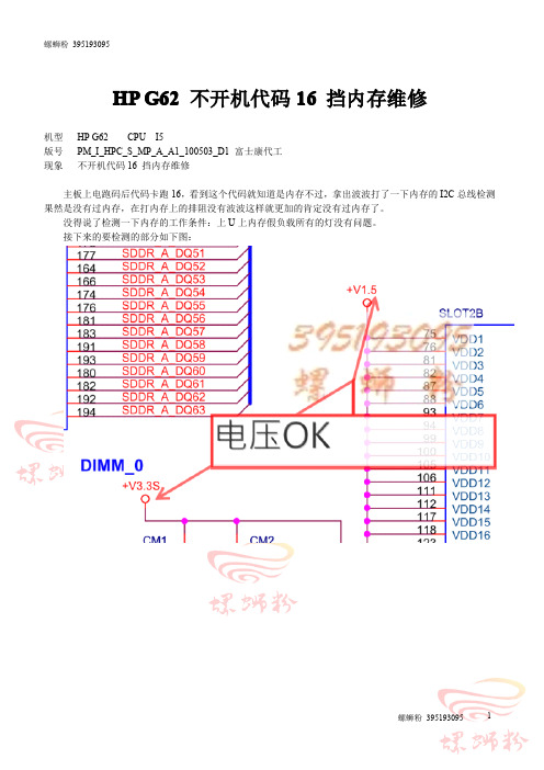
HP G62不开机代码16挡内存维修
机型HP G62CPU I5
版号PM_I_HPC_S_MP_A_A1_100503_D1富士康代工
现象不开机代码16挡内存维修
主板上电跑码后代码卡跑16,看到这个代码就知道是内存不过,拿出波波打了一下内存的I2C总线检测果然是没有过内存,在打内存上的排阻没有波波这样就更加的肯定没有过内存了。
没得说了检测一下内存的工作条件:上U上内存假负载所有的灯没有问题。
接下来的要检测的部分如下图:
这时测到了内存没有复位信号。
从图上分析这个复位信号是由CPU发出的。
现在把QX3断开后在测DDR3_DRAMRST#有0.4V左右的电压,在内存上可以测到波波但还是不过内存,这样就可以肯定必须要有DDR3_DRAMRST#这个信号。
这样看来是CPU没有发出DDR3_DRAMRST#这个信号,那CPU为什么不发呢?检测CPU的条件发现
根据手册得知这个时候输入和输出是正确的,但是VTT_PG这个是电源合格信号是不会为低的。
把电阻装上好了开机过内存,从这个案例可以得到这样的思维当CPU收到合格的DRAM_PWRGD信号后在开机时才能发出合格的SM_DRAMRST#信号,同时CPU才能完成对内存的检测工作。