涂油机说明书
Mambo专业技能3-1-B 涂油设备操作手册v1.0

涂油设备操作手册Rev1.01. 介绍1.1用途及范围此调试手册适用于点胶设备组装完成后的初步调试,包括调试的基本内容和参考流程,以及出货前的验收标准。
涂油设备操作手册Rev1.02. 设备调试基本项目2.1检查软件升级MPC6568固件(1) 将MPC6568的升级固件(6568V***.FMW、6568V***.HDW)拷贝到U盘根目录下。
(2) 系统关闭电源。
(3) 把U盘插到MPC6568卡上,如下图所示,红色方框内的USB口。
(4) 开启机器电源,等待大约20秒,拔下U盘,升级完成。
(5) 系统上电,示教盒UI02主界面下,操作按键“5”,进入系统设置界面,查看MPC6568的固件版本号(DSP与FPGA版本号),确认升级是否成功版本号以实际升级版本为准升级UI02固件(1) 关闭机器电源。
(2) 把U盘插到示教盒右侧的USB孔中。
涂油设备操作手册Rev1.0(3) 开启机器电源,等待升级。
(4) 界面上显示升级过程,升级完后示教盒会长鸣。
拔下U盘,示教盒升级完毕。
2.2伺服驱动器参数导入☆如遇马达运行异常,先将马达的参数恢复出厂设置再进行手动配置1.用专用的伺服连接线连接工控机与相应的伺服驱动器,串口连接至设备后方相应转接口,网口连接至相应伺服驱动器网口。
2.打开伺服参数设置软件“IS_Opera.exe”,如下左图所示,如出现如下右图所示界面,请点击“取消搜索”;3.弹出如下图所示参数设置界面后点击左上角红框所示串口形状图标涂油设备操作手册Rev1.04.弹出如图所示窗口,选择“否”自行进行串口设置;如弹出需要输入密码的界面,请点击取消,然后将上图右侧红框中勾选项取消掉;5.按上所示设置端口号及波特率,然后点击“打开串口”会弹出如下图所示连接成功提示,如出现问题,请更换连接线或者端口重新尝试;涂油设备操作手册Rev1.06.点击参数配置窗口中间红框所示图标,弹出如下图所示界面,选择对应的最新参数后点击“打开”按钮;7.弹出如下图所示窗口,点击确定8.完成后弹出如下图所示完成窗口,点击关闭即完成一个伺服驱动器参数的设置;涂油设备操作手册Rev1.09.用同样方法导入其他四个伺服电机参数。
静电涂油机的应用

静电涂油机的应用L涂油机的构成和工作原理1.1 静电涂油机的构成1.1.1 静电涂油机的基本参数静电涂油机的涂油范围为0.3-3∙0g∕m2,涂油精度可保证在涂油设定值得±10%以内,高压值可调范围为O-IooKV,实际值可根据冲压保护油的质量和现场情况调整,在南山板带机组一般都在60-90KV。
涂油生产速度最快为IOOm∕min,为了达到良好的涂油效果,涂油生产速度应保证在50-65m∕mi∩o1.1.2 涂油机的组成部分该静电涂油机包括四部分:密封的涂油室、供油及加热系统、高压电源系统和程序控制系统。
涂油室是密封的,入出口有20Cm的开口空间缝隙,这样可以防止带电荷的工艺油外溢;涂油室内上下各有一根涂油刀梁,涂油刀梁上接有负高压静电,与作为接地极的铝带形成高压电场。
供油机加热系统包括涂油泵站、回油箱及加热油箱三大部分供油泵站设有两台计量泵,由直流电动机驱动,分别为上、下刀梁提供定量的工艺油。
高压电源系统由高压变压器、高压控制柜和高压电缆组成。
用于为静电涂油机的涂油刀梁提供O-IOoKV直流高压。
加热系统采用320型号导热油进行加热,导热油设置温度为冬天118℃,夏天110℃。
导热油的循环方式采用齿轮泵循环,主管路加热循环方式为离心泵。
1.2 静电涂油机工作原理供油系统依据控制系统所给信号将源源不断地将工艺油供给涂油室内的涂油刀梁;涂油刀梁与高压电源系统的负极相接,行进中的铝带为接地。
油液从刀梁、喷嘴的刀口狭缝中均匀地流出。
高压静电源输出60-8OKV左右的负直流高压,加在涂油刀梁,使刀梁和作为接地板的铝板之间产生高压静电场。
当油雾进入静电场时,它会被带上负电荷。
由于铝带接地,相对于油雾颗粒处于正电位。
根据静电原理,同性相斥,异性相吸。
带有负电荷的油液在高压静电场中雾化并被吸附在铝板表面上,形成匀薄的油膜。
2 .涂油效果的影响因素2.1 电压对涂油效果的影响和选择带电油滴在静电场中主要是受电场力的作用而运动。
喷涂专用设备使用说明书

喷涂专用设备使用说明书1. 适用范围本产品为水性液体橡胶涂料专用双组份隔膜式无气喷涂机,主要用于防水行业进行液体橡胶涂料喷涂施工。
由于它是一种特殊专用泵,不可随便使用。
2.主要技术参数A组分 B组分最大压力30bar最大压力30bar最大流量 30L/min 最大流量 20L/min3.使用方法3.1 使用前基本要求1)发动机燃料:90#以上无铅汽油,(加入量见发动机说明书);2)发动机机油:32#机油(加入量见发动机说明书);3)泵体润滑油:30#耐磨液压油,新机加入量A组分及B组分各加入0.3L; 4)检查确认A、B组分泵体顶盖蓄压保持≥0.7MPa;5)确认整机是否根据安装要求安装,并以放置牢固,整机螺丝一定要拧紧,不可有松动;6)准备30目不锈钢丝网布,以过滤A、B组分的液体料。
3.2 安装1)将两个组份的吸入软管分别插入喷涂机前接口板的吸入接头上,用卡箍抱紧。
新机已经使用,吸入管不得交叉混用,以免两个组份混合,造成泵体损毁;2)将双色高压管分别接入喷涂机前接口板的输出接头上,其中红管接A 组分,兰管接B组分,随后,将双色管分别与喷枪进行连接,左为A组分,右为B组分;3)将喷嘴装入喷嘴的螺母中,垫上垫圈,拧紧固定在喷枪上,喷枪嘴左大(A)料,右小(B)料;4)打开A、B组分位于调压手柄处设入准备投入使用的输出管道的球阀;5)关闭A、B组分位于调压手柄处未使用输出管道的球阀;3.3启动及操作1)将压力调节阀逆时针调制最小;2) 将吸入管放入涂料桶,放泄管放入废料桶;3)启动发动机,转速保持在全速的1/3处;4)吸入涂料,排除管道内的空气;5)将放泄管放入涂料桶,调高转速和加大压力;6)开启喷枪至正常喷涂;7)依据喷嘴大小调整喷枪前段连接端头,使两个组分的喷雾交叉混合于喷涂点(注意应先松开喷嘴螺母,调整喷嘴角度使喷雾可行),交叉点离喷嘴15~20公分。
注意:(1)从进口自吸能力来考虑,当进口里有空气时,那么泵在启动时,输出压力或流量从小到大逐渐加大,如果泵在启动前,里面已充满液体,则可以随便启动。
【优质文档】涂油机作业指导书-范文模板 (13页)
本文部分内容来自网络整理,本司不为其真实性负责,如有异议或侵权请及时联系,本司将立即删除!== 本文为word格式,下载后可方便编辑和修改! ==涂油机作业指导书篇一:过油机作业指导书1. 目的增加印刷品的光亮度及保护印刷表面图文作用。
2. 适用范围适用于本公司过油部生产运作过程控制。
3.书参考文件3-1《过油机操作说明》(31017)3-2《过油机保养说明》4. 定义:无5. 工具:活动扳手、螺丝刀、六角扳手等辅助工具。
6. 职责:6-1 后加工主管:6-1-1负责本程序的维护及监督。
6-1-2负责过油/UV技能培训。
6-1-3负责生产排期及品质监控。
6-2 机长:6-2-1负责按本程序的规定进行生产运作。
6-2-2 负责助手的技术指导及品质监控。
6-2-3负责机器加油及保养。
6-2-4负责执行生产编排表。
6-3助手:6-3-1按本程序指引及机长的安排配合生产操作。
6-3-2负责协助机长搬运物料及来料检查。
6-3-3负责收纸、抽检及货品的摆放。
6-3-4负责随时清扫机台周围卫生。
6-3-5负责物料的领取。
7.程序:7-1过油/UV前准备:7-1-1由后加工主管提前对生产排程及资料袋内容预审,资料齐全清晰后,跟进产品,安排生产。
7-2过油/UV准备:7-2-1由助手根据机长的要求备好上光涂料。
7-2-2来料检验,过油/UV前是否有印刷粉大、混料、皱纸油墨未干及数量不够现象。
7-3 调机:7-3-1机长通过手动调试机器的压力,按上光亮度的要求、涂料的比例来调配光油。
7-3-2 查看是否有上光不均匀、打皱及掉色等现象。
7-4首件程序:7-4-1在各要求接标准时,进行首件检验,由机长执行内容包括:(1)以样为标准,看光度是否符合要求。
(2)检验表面是否有掉色、打皱、脱油、涂油不均及亮度不够。
(3)切实执行以上首检,并确保达到客户要求后,方可批量生产。
7-4-2过吸塑油产品首检程序:(1)需吸塑产品的纸张需测试OK后,方可安排切纸部切纸。
涂油机使用说明

静电涂油机使用说明书 2011年5月1、说明JT-17D型静电涂油机是根据生产工艺要求设计和制造的钢卷静电涂油设备。
2、技术性能1.涂油工作宽度:1700毫米;2.单面涂油量:0.3~2.5克/米2;连续可调;带速低于80米/分时,涂油量将大于0.3克/米23.可单面涂油,亦可双面涂油;4.机组带钢运行速度:V=30~400米/分;5.机组速度变化时,预设定的涂油量可以保持不变;6.高压工作电压:直流50~80KV,连续可调;7.总功率消耗不超过15KW;8.高压供电系统具有闪烁保护、短路保护功能;4设备组成及功能静电涂油机由涂油室、供油及加热系统、高压电源系统、电控系统及操作台四大部分组成。
3.1 涂油室涂油室为钢板制作的箱体,在传动侧有一个门和操作侧有二个门,门上镶有供观察用的有机玻璃窗。
涂油室内有绝缘材料制作的上下导板,用来保护涂油刀梁不受带钢头尾的损伤。
涂油室内可安装2根涂油刀梁(上下各1根)。
刀口宽度1700mm,刀梁内部有加热装置,用热循环油加热刀梁。
刀梁上接有负高压,与作为接地级的带钢形成高压电场,当防锈油从刀梁的刀口狭缝中流出时,即被微粒化,吸附在钢板上。
上下刀梁均设有大油量冲洗装置,用于清洁刀口。
刀梁安装于绝缘材料制作的刀梁悬挂装置上,其高度及角度可调节。
两套刀梁移出机构可以方便地将刀梁移出涂油室,进行维修或更换。
刀梁和钢板之间装有油液雾化装置,可促进油液雾化过程,降低高压工作电压。
二套高压电缆快速联接装置使高压电缆和刀梁的联接既快捷又可靠。
二套高压闪烁火花限制装置可有效地限制涂油刀梁对带钢或机壳之间出现的高压闪烁电流,确保设备安全。
上刀梁的下方有接油槽,不涂油时接油槽将自动移到上刀梁下方,防止上刀梁中剩余的油滴落到钢板上。
接油槽由气缸驱动。
涂油室的侧面装有绝缘材料制作的防护板涂油室顶上装有高压工作指示灯,红灯表示高压接通。
侧门的旁边设有接地棒,打开侧门后,高压电源将自动切断,但仍应使用接地棒使高压系统放电,以确保人身安全。
喷涂机说明书
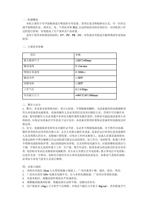
一、机器概述本机主要用于对平面板材进行喷涂的专用设备。
采用往复式喷枪移动方式,可一次性完成平面喷面作业。
利用光、电、气等技术和PLC自动控制技术的有效结合,对该机的工作过程进行控制,有效提高了生产效率及产品质量。
适用于使用本机喷涂的涂料:UV、PU、PE、NC、水性漆及其他适合板材喷涂作业的涂料等。
二、主要技术参数三、警告与安全1、警告:本设备安装和移动时,须小心轻放,不得碰撞和翻转。
为设备提供的电源规格须符合本设备的电源要求。
设备的操作人员必须是经过培训合格的人员,否则不可以操作本设备。
使用的操作人员必须遵守各项安全操作规程及操作说明,否则有可能造成设备和人员的损害。
应保证该设备在空车状态下运行良好。
本设备在使用时要保证设备所用电源电压时稳定的。
2、安全:电源接线者是持有安全操作证书者,无证者不得接线或电源,并不得开启电源。
操作者须是经过培训的合格人员,无关人员禁止操作本设备。
设备在运行时须注意设备操作人员及周围人的安全。
衣服袖口要收紧,以免在工作时衣袖卷入,造成人员或设备的损害,设备运转时不得去触摸正在运动的或可能会运动的部位,如工作台,电控柜等。
机器工作时不得移动或拆卸防护罩。
加注润滑油时应停机,且关闭所有电源开关。
应保持整机的清洁与干燥,不得在灰尘高的坏境下工作。
生产前,要空车试车,检查各部分的运转动作是否有异常。
电控柜内有高压及精密的电脑配件,非专业人员禁止打开电控柜;禁止带电打开电控柜;注意在关电一分钟内,电柜内可能存在对人体有危险的残余高电压。
如果电气系统有故障,必须由专业电气技术人员进行维修。
四、安装与调试1.本机应安装在20cm左右厚的混凝土地面上,厂房内要求干燥、通风、清洁、明亮。
2.厂房内应设有380v电源及电源开关,且与本机电器接通,厂房内应有消防设施。
3.安装本机时,使输送部件保持水平传递状态。
4.调整输送链条的松紧,使输送部分运转平稳,无跳动及异音。
5.用户要备有12kg,1立方米空气压缩机,并保证气源压力不低于8kg/cm²。
静电涂油机操作与维护

1.1
静电涂油机由整个涂油室和供油油箱系统组成。每套油箱是由下部的工作油箱和上部的辅助储油箱完全封闭组成。储油箱是通过球阀与下部的工作油箱连通的。球阀的位置在打开位置。
工作油箱的油通过加热杆可以加热到40-60°C。油温由自动调温器和温度计检测、控制。
储油箱的液位通过液位计显示。
油箱设置了三点液位开关,液位开关安装在一个不锈钢的导管中,液位开关位置可调。一个带永磁铁的浮筒在导管外部随着液位移动。当浮筒从导管中的液位开关接触点旁经过的时候,浮筒将激活液位开关的接触点,从而可以产生通、断功能。
1.2.6
为安全起见(机器内部的高压),在涂油室和高压柜的门上都安装了安全开关用于监控门的开关状况。如果门打开,涂油机屏幕会显示“涂油室门开,请关好门”,同时高压将无法启动。在所有被监控的门被关闭以前,涂油机是不会显示安全门关闭的信号的。
1.2.7
为保护高压电路部分的熔丝,涂油机集成了过流断电的功能。一旦涂油机内部出现了严重的放电现象或是刀梁偶然接地(例如:搭上废边),过流保护功能一定要立即切断高压电路。过流保护功能将在调试期间确定,标准的过流保护电流为1.0mA。设定的过流保护电流值编程到高压变压器中。
通过将接地插头连到机器机架上来检查高压连接器是否切断。然后手动增加高压同时观察电流指示。调节过流保护继电器的整定值使其在期望的值(1mA)时释放动作。
1.2.8
为了防止在油箱空的状况下,涂油机运转和工作油箱加热器干烧。油箱系统设置了可视的液位监控系统。当液位到达临界的最低点,过滤泵和加热装置将不能启动。此时,只有将油箱充满才能再次启动。
三个接触点分别有以下功能:
●第一个开关点用于给自动加油泵停止加油的信号。
也是屏显示油位高位信号
●第二个开关点用于给自动加油泵开始加油的信号。
切边涂油作业说明书 新
涂油机作业指导书一、涂油机油箱的选择和涂油量可以在出口HMI上进行操作,在HMI画面中涂油量是以mg/m²为单位,而操作面板上时是以g/m²为单位。
HMI的报错信息有4条,分别是:Communication Fault 通讯故障General fault 一般故障,当某个油箱空时,会报此故障。
Ready 准备条件t要具备Oiler in remote 涂油机选择远程模式,在操作面板中选择。
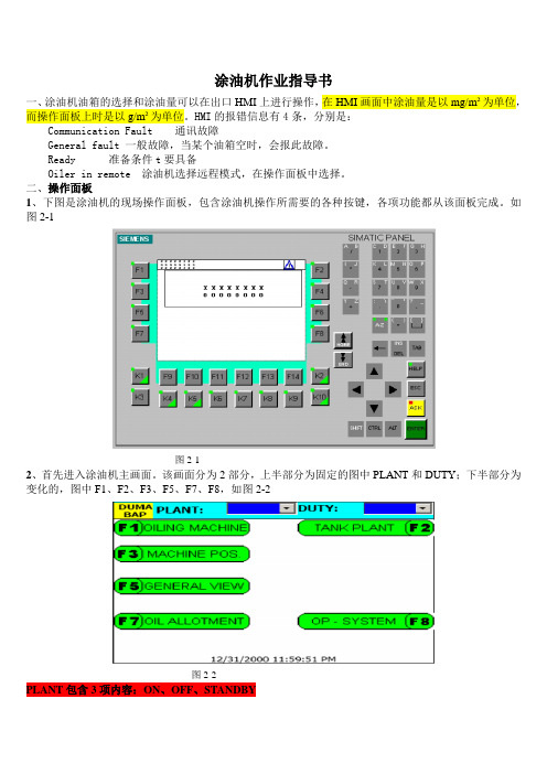
二、操作面板1、下图是涂油机的现场操作面板,包含涂油机操作所需要的各种按键,各项功能都从该面板完成。
如图2-1图2-12、首先进入涂油机主画面。
该画面分为2部分,上半部分为固定的图中PLANT和DUTY;下半部分为变化的,图中F1、F2、F3、F5、F7、F8,如图2-2图2-2PLANT包含3项内容:ON、OFF、STANDBY使用涂油机时,PLANT 必须处于ON 模式;检修维护时处于OFF 模式;短时间不涂油时使用STANDBY 模式,保证油箱处于正常工作状态,以保证上下刀梁的油温,可以随时投入涂油机;如果检修时间过长并且模式处于OFF 状态,下次使用时一定要对刀梁进行预热,大约需要2个小时。
DUTY 包含3项内容:MANUAL 、ANTOMATIC 、REMOTEMAMUAL 只用于测试;ANTOMATIC 所有的参数只能在本地操作面板更改;REMOTE 从出口HMI 或着L2控制下半部分为子画面调用:从操作面板上按下‘F1’键,进入‘OILING MACHINE’子画面,此画面为涂油机机架部分画面。
从操作面板上按下‘F2’键,进入‘TANK PLANT’子画面, 此画面为涂油机油箱部分画面。
从操作面板上按下‘F3’键,进入‘MACHINE POS.’子画面, 此画面为涂油机在线、离线驱动画面。
从操作面板上按下‘F5’键,进入‘GENERAL VIEW’子画面, 此画面为涂油机所有状态画面,不能操作,只能显示。
静电涂油机

静电涂油机二、静电涂油机2.1设备功能概述涂油机布置在出口飞剪前,为机电一体机,根据带钢速度进行精确的涂油输出控制,为带钢双面或单面涂油,以达到抗腐蚀或润滑的目的,起到保护作用。
静电涂油机由涂油室、供油及加热系统、高压电源系统、电控系统操作台四个部分组成。
油箱里的油由计量泵输出直至上下刀梁内,上下刀梁各有一个高压发生器,通过高压发生器使油滴分解成油雾并带负电荷;带钢是接地的,因此刀梁与带钢之间形成电场,带负电荷的油雾向带钢移动,从而完成涂油过程。
设备技术参数 2.21.最大涂油宽度:1500mm;机组生产速度40-190m/min;2.涂油方式:单面涂油,或双面涂油;涂油量调节方式:上下刀梁涂油2量可单独、连续;钢板表面涂油量:单面涂油量为0.3,2.0g/ m;(带速低于270m/min时,涂油量?0.3g/m)。
涂油质量不受环境温度响; 当机组速度变化时,供油量根据带钢速度自动变化,保证板面涂油量保持不变;机组平稳运行时,实际涂油量和设定涂油量间的误差不超过?10%;钢板两侧边缘50mm范围内实际涂油量误差不超过?20%;在静电涂油机的操作箱面板上有触摸屏及常用按钮,可设定及显示涂油机的工艺参数、工作状态及故障部位。
3.涂油机刀梁便于清洁、维护和装卸,在机组不停机的情况下,上下刀梁可以分别移出涂油室进行清洁、维护;可以在不剪断带钢的情况下,向传动侧横移离线, 4.涂油室采用C型框架结构,实现快速检修;涂油室移动时具有声光报警功能;5.静电涂油机具备远程控制及就地控制两种操作方法;静电涂油机具备自动与手动两种工作状态;在自动工作状态下,涂油机无需人工操作,可随机组的开车(停车)自动开始(停止)涂油;静电涂油机有可靠的安全保证措施(包括:接地棒、开门自动断电和高压警示灯等)和闪烁、短路保护措施;26.涂油机可使用3种静电防锈油,(运动粘度10,25mm/s ,40?时);机组运动方向,从操作侧看,从右至左;机组作业线高度,3450mm;作业线与涂油机移动轨道表面之间1400mm;7.静电涂油机工作电压:直流50-80KV'使用电源:三相交流380?10,V,50?2,HZ,总功率不超过18KW(不需要UPS);8.使用压缩空气:压力0.4,0.6mpa,最大用量20Llmin(接口管径:φ14,接头形式:焊接接头)。
钢轨自动涂油器 产品说明书pdf

一.前言近年来,随着列车速度和轴重的不断提高,钢轨和轮缘的磨耗也相应的增加。
电力机车在大量曲线区段运行时钢轨侧磨现象比较突出,轮对的维修周期也相应的缩短。
下图表示钢轨和车轮的最大磨合区域。
它们之间的垂直运动和较大的横向力是磨耗产生的原因,钢轨和车轮接触区域的滑动摩擦是磨耗产生的条件。
在这种情况下,为提高轮毂和钢轨的使用寿命,我公司于2004年开发研制成了第二代GDBK-16型光电感应钢轨自动涂油器。
经过实践使用该产品,既解决了钢轨小半径曲线侧磨的问题,也降低了因列车轮对与钢轨摩擦产生的强烈噪音,既保护了环境,节约了能源,又降低了维修费用。
二.主要技术参数1.每通过一列车耗油量3-15g(可调);2.列车运行速度20-140Km/h;3.储油箱有效容积40l;4.涂油长度≥500m;5.光电传感器检测距离≥1.5m;6.电源参数:AC220V 1A 50Hz;7.工作方式:自动模式手动模式三.主要结构及工作原理1.主要结构GDBK-16型钢轨自动涂油器是由自动控制系统和供油系统组成。
自动控制系统是由光电传感器、PLC、触摸屏、稳压滤波电路、驱动电机组成。
供油系统是由储油箱、齿轮油泵、调节阀、导管及出油夹板组成。
1.1箱体结构1.2涂油板结构2.工作原理2.1 自动控制原理GDBK-16型钢轨自动涂油器的工作原理是:当列车车身通过光电传感器的检测区域时光电传感器输出一个ON信号,给PLC的输入点,PLC即输出一个开关量信号,驱动齿轮泵工作。
油泵压出的油脂经导油管送到涂油板的端部,由列车轮缘携带,涂抹到曲线钢轨外轨内侧磨耗面上,形成一层油膜。
列车经过曲线线路时,车轮轮缘是沿曲线钢轨外轨内侧导向行驶的,因此轮缘就和钢轨内侧紧密贴合,这时外轨内侧磨耗面上的油膜就起到减缓钢轨与轮缘磨耗的目的。
2.2 手动控制原理在调试、测试时使用手动控制,依此来调整涂油量,调试、测试结束关闭手动控制。
四.操作规程GDBK-16型钢轨自动涂油器是采用PLC和触摸屏组合自动化控制系统,全面提升了涂油器的自动化程度。
连续通过式涂油机技术参数
连续通过式涂油机技术参数连续通过式涂油机是一种常用于食品、医药等行业的设备,主要用于对各种片状、带状、薄膜状产品进行涂油。
该设备工作原理简单,操作容易,且具有高效稳定性的特点。
其技术参数如下:一、涂油速度连续通过式涂油机设计速度可达30米/分钟,速度可根据不同工艺要求进行调整。
实际工作速度取决于工作件大小、形状、涂料性质等因素。
通常,涂油速度越快,生产效率越高,但涂层质量也可能受到影响。
二、涂层厚度涂层厚度是涂油机的重要参数之一,通常根据生产需要进行调整。
该设备可实现0.01-3mm之间的涂层厚度,因此适用于不同种类和规格的产品。
该设备可通过自动控制系统进行自动调整,确保涂层厚度均匀一致。
三、涂布宽度涂布宽度通常由工件的宽度和涂料喷淋系统的设计参数共同决定。
涂油机可实现5-1200mm的涂布宽度。
该设备可根据实际需求进行调整,以实现涂布宽度的变化。
四、刮板间隙刮板间隙通常用于调节涂层厚度和涂油速度。
间隙过大可能导致涂层不均匀,而过小则会增加电机负荷,甚至导致设备故障。
通常,刮板间隙为0.01-5mm,可根据实际情况进行调整。
五、工作温度该设备通常需要在一定的工作温度范围内进行操作。
工作温度取决于涂料的特性,一般在常温到200度之间。
当涂料的粘度较大时,可增加温度以降低粘度,从而提高涂层均匀性和操作效率。
六、驱动方式涂油机的驱动方式通常是由电动机提供动力,该设备通常采用变频调速器进行调节,以满足不同工艺要求和产品规格的涂油速度和涂层厚度。
连续通过式涂油机是一种高效稳定的设备,其技术参数的合理调整可以确保生产过程中的稳定性和涂层质量的一致性。
根据实际需求进行调整,也能够满足不同产品规格和工艺要求的涂油需求。
除了以上所述的基本技术参数,连续通过式涂油机还有其他一些值得注意的特性和参数。
(一)材质选择连续通过式涂油机通常由钢材、不锈钢、铜、铝等金属材料制成。
不锈钢为涂油机的常用材料之一,因为它能够抵抗涂料的腐蚀,并且易于清洗。
油漆喷油机使用方法

油漆喷油机使用方法
油漆喷油机是一种非常方便的工具,可以帮助我们快速、高效地涂抹油漆。
但是,如果使用不当可能会造成浪费和安全隐患。
下面我将介绍一下油漆喷油机的正确使用方法。
首先,使用油漆喷油机前要确保工作区域通风良好,以防止油漆喷出后对人体造成损害。
同时,要穿戴好防护装备,如口罩、护目镜和手套,以保护自己免受油漆颗粒的影响。
其次,要对油漆喷油机进行正确的组装和调试。
按照说明书的指导,将喷枪和喷涂系统组装好,并确保所有连接处都紧固牢固。
然后,调试喷油机,确保喷涂的压力和喷涂的角度都符合要求。
接下来,准备好需要喷涂的物体和油漆。
在喷涂前,要先对物体进行清洁和打磨,以确保油漆可以附着在表面上。
选择适合的油漆类型,并按照说明书要求将油漆稀释至合适的浓度。
喷涂时,要保持喷涂机与物体表面的适当距离,并保持均匀的喷涂速度和角度。
在喷涂过程中,要避免出现漏喷或者重叠喷涂的情况,以免造成油漆的浪费。
最后,喷涂完成后要及时清洁喷涂机和喷涂系统,以防止油漆残留导致设备损坏。
同时,要妥善处理废弃的油漆和清洁液,以免对环境造成污染。
总的来说,油漆喷油机是一种非常实用的工具,但是在使用时一定要注意安全和正确的操作方法,以确保工作效率和人身安全。
希望以上方法能够帮助大家正确地使用油漆喷油机。
涂油机
SZT型涂油(漆)机说明书设备用途:SZT型涂油(漆)机是用于圆管外表面喷涂油(漆)的高效专用设备,它能增加圆管外表面的防锈蚀和改善产品的外观形象。
技术参数:1:圆管规格:180型:φ60.3---φ177.8340型:φ139.7---φ339.7660型:φ219.1---φ6602:圆管长度:6---13.5M3:气动系统工作压力:0.4---0.6Mpa4:供油(漆)泵工作压力:0.55Mpa5:圆管弯曲度:≤0.2%设备组成与功能:1、供油(漆)系统由齿轮泵、电磁阀、调节阀及管道组成,回油槽与油箱联通,具有使防锈油(漆)循环输送和调节流量的功能。
2、供气系统由气动电磁阀及管道、调节阀等组成。
主要用于控制、调节喷气装置压缩空气的流量。
3、喷油(漆)装置由若干个小孔的喷油(漆)环组成。
它按客户要求的最大尺寸设计,其余较小的尺寸通用。
4、喷气装置由可调整的内外喷气环组成。
采用专利技术设计,专利号为:ZL002 26766.7。
5、托辊装置由被动V型辊组成。
如有必要,客户可提供辊型尺寸,以便于统一。
6、过滤装置由滤网和进出口油(漆)组成,可方便拆卸清洗,用于防锈油(漆)的回收、过滤循环使用。
7、排气装置由矩形开口的集气罩组成。
用于排除废气,也可根据客户要求提供排气装置。
8、储气装置由储气包和输气管道组成。
根据涂油机的使用要求,配置0.5—2立方米的储气包。
9、箱体由钢板组焊而成,用于支撑其他各装置并兼有油箱的功能,外表按用户的要求喷磁漆并有镀铬装饰件。
10、电控系统。
由电控箱、继电器和传感器等组成。
通过传感器和继电器使钢管进入和退出本机时实现自动喷油(漆)和喷气,调整正确后基本实现无人管理。
设备动作描述:1、圆管由涂油机前上位工序输入。
其输入的方法如:①V型辊道有单独转动和输送链串联两种形式。
②带有V型托板的特制输送链,一般情况下由步进装置配合。
2、涂油机工作前应认真进行工艺调整,主要有如下内容:①调整喷油环与圆管的垂直中心线相重合,圆管下方外表面与喷油环内表面间至少应有30—50mm间隙。
L72M和L72C油雾喷涂设备安装与维护指南说明书
L72# - ### - ###
L72M, L72C
Installation & Maintenance Instructions
Bowl
Type
Port
Thread Form
Air Flow Direction
Drain
W...Long transparent with guard
TECHNICAL DATA
Fluid: Compressed air Maximum pressure:
3. Oil-Fog Lubricators - Determine the average rate of flow
thru the lubricator. Turn green rotator in sight feed dome
decrease the drip rate. Total travel of rotator is 320°.
Micro-Fog
Metal bowl: -20° to +65°C (0° to +150°F)
4. Micro-Fog Lubricators - Determine the average rate of
(4) to obtain one drop per minute for each 5 dm3/s (10
4
Transparent bowl: 10 bar (150 psig)
scfm). For example, if the average flow is 19 dm3/s (40
Metal bowl: 17 bar (250 psig) Operating temperature*:
转台式清洗涂油机操作规程
转台式清洗涂油机操作规程该设备是采用平面转台输送传动,具有清洗、涂油、甩干等功能的专用型清洗涂油设备。
一、 使用者须知1. 首次使用本机前,操作者应先阅读转台式清洗涂油机说明书,了解本机结构、性能以及操作、保养等方面的知识。
2. 操作者须经过培训后才能上岗。
3. 设备使用前一定要接好地线,使设备可靠接地。
4. 操作者在本机工作中,因故离开,要切断电源、夜源及压缩空气气源。
5. 设备长时间不使用时,需将设备内液体排放干净,以防止冬季结冻。
6. 经常观察槽体液位并及时添加液体。
如:液位不足时,液泵就会因缺液而损坏,液泵严禁缺液使用。
7. 该设备清洗介质为易燃品(煤油),设备现场要有标识:“严禁烟火”。
二、 操作流程1. 该设备设置手动、自动两套功能模式,通过选择按钮选择设备运行模式。
1) 手动模式:该功能作为设备调试和检修维护时使用,按下相关按钮执行相关动作。
2) 自动模式:设备自动启动后,各功能部件顺序启动,工件放置于小转台工装上后确认,每次大转台回转90°,进步完成工件清洗、漂洗涂油、吹(甩)干。
3) 甩干速度, 调整变频器频率,设计速度约200r/min (50Hz ),转台设置检测开关,以保证转台回转90°后自动停止。
4) 节拍调整方式:设两档,1档总时间为90s ,2档总时间为120s;2. 人工在上下料端进行上下料,每完成一次上下料后,必须确认后方可执行下一个循环。
三、 日常维护保养1. 每班清除提篮中的渣滓,当压差报警时,应立即停止作业并清理过滤元件。
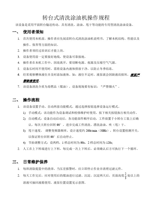
2. 每天工作完后,应对使用后的煤油进行过滤、沉淀,沉淀两天后,页面高度32处以上的溶液可抽回液箱使用。
液泵位置设置见示意图。
示意图3.定期对煤油进行更换,大约8000件更换一桶煤油,9000件更换一桶防锈油,更换之前必须将机床及滤网等清洁干净。
4.每周对设备内部,油池进行打扫,清除杂质,并对布袋式精过滤器清洗其上的杂物和污垢。
涂油机使用说明(酸洗)

酸洗机组静电涂油机一技术参数1涂油机工作宽度:1700mm.2单面涂油量:0.5-2.0克/米²;连续可调;带速低于65米/分时,涂油量将大于0.5克/米²。
3可单面涂油,亦可双面涂油.4带钢运行速度:V=30-250米/分.5带钢速度变化时,预设定涂油量可以保持不变.6工作电压:直流50-80KV.7总功率消耗不超过15KV.8高压供电系统具有闪烁保护,短路保护功能.9使用国产钢板防锈油.二设备组成及功能:静电涂油机由涂油室、供油及加热系统、高压电源系统、电控系统及操作台四大部分组成.1涂油室:涂油室为钢板制作的箱体,在传动侧和操作侧均有门,门上镶有供观察用的有机玻璃窗。
涂油室内有绝缘材料制作的上、下导板,用来保护涂油刀梁不受带钢头尾的损伤。
涂油室内装有2根涂油刀梁(上、下各1根),刀口宽度1700mm,刀梁内部有加热装置,用热循环油加热刀梁。
刀梁上接有负高压,与接地形带钢形成高压电场,当防锈油从刀口狭缝中流出时,既被微粒化,吸附在钢板上,如刀口狭缝有脏物,可用刀梁设有的大油量冲洗装置、清洁刀口。
刀梁安装在绝缘材料制作的刀梁悬挂装置上,其高度可调节。
另设有两套刀梁移出机构,可供维修或更换时将刀梁移出涂油室。
上刀梁的下方有接油槽,不涂油时接油槽将自动移到上刀梁下方,防止上刀梁剩余的油滴落到钢板上。
出口侧的下导板是活动导板,为了保护下刀梁,在穿带或下刀梁不涂油时,该活动导板可以由垂直打开位置转到水平关闭位置。
接油槽和活动导板分别由气缸驱动。
涂油室的侧面装有绝缘材料制作的防护板。
刀梁和钢板之间装有油液雾化装置,可促近油液雾化过程,降低高压工作电压。
涂油室内配有两套高压电缆快速连接装置供高压电缆和刀梁的连接既快捷又可靠。
配有两套高压闪烁火花限制装置可有效地限制涂油刀梁对带钢或机壳之间出现高压闪烁电流,确保设备安全。
室内装有加热管道,必要时可用蒸汽加热提高涂油室地温度。
涂油室顶上装有高压工作指示灯,红等表示高压接通。
- 1、下载文档前请自行甄别文档内容的完整性,平台不提供额外的编辑、内容补充、找答案等附加服务。
- 2、"仅部分预览"的文档,不可在线预览部分如存在完整性等问题,可反馈申请退款(可完整预览的文档不适用该条件!)。
- 3、如文档侵犯您的权益,请联系客服反馈,我们会尽快为您处理(人工客服工作时间:9:00-18:30)。
OPERATING INSTRUCTIONSPRAY CHAMBEREOS III – PC – 4100SATG - FORD - CAF05-00105-001Accompanying documents:Declaration of conformityInstructionIssue RegisterContents 00 0 General notes 00 1 General safety instructions 00 2 Technical data and 00 3 technical descriptionPackaging, transport and 00 4 storageSetting up and installation 00 5 Commissioning and operation, 00 6 taking out of serviceMaintenance and repair 00 7 Spare parts and parts lists 00 8 Drawings and plans 00 9 Purchased parts 00 1005-001EU Manufacturer´s Declarationaccording to Appendix II A of the EU Machinery Directive (98/37/EG)The manufacturer:E ckardt Umformtechnik GmbHWestliche Gewerbestrasse 2D-75015 Brettenherewith declares that the machine describedbelow:Spray chamber EOS 3 - 4100 PCaccording to drawing No.: 109745-3is a machine ready for use within the meaning of the EU Machinery Directive and corresponds to the requirements of this directive. Commissioning the plant is not allowed until it is determined that the total plant in which it is integrated corresponds to the EU Machinery Directive! Applied EU directives:0 98 / 37 / EWG1 73 / 23 / EWG 0 Machinery Directive1 Low Voltage DirectiveApplied harmonized standards:2 DIN EN 602043 DIN VDE 0470 – 14 DIN EN 4145 DIN EN 10502 Safety of machines, electrical equipment4 Types of protection by housing5 Safety of machines, possible hazard6 Safety of machines, causes of hazardDesign changes which have effects on the technical data stated in this product description and the use as intended, there fore essential changes, make this declaration of conformity invalid!Bretten, 14. April 2005Jochen Eckardt, Managing Director05-001Instruction No.:I here with confirm by my signature that I was instructed before starting work on the spray chamber.I have read and understood the operating instructions and especially the safety instructions.Remarks SignatureDate Name Department Plannedwork05-0011. General notesThese operating instructionsare directed without exception to all persons who have to do with the transport, setting up, the installation, the operation, the maintenance, the repair or storage of the spray chamber andshould simplify for them all work in connection with the spray chamber andmake them familiar with the principles and mode of operation of the spray chamber.It contains important technical information about the spray chamber andimportant notes in order to operate the spray chamber safely, correctly and as intended.These operating instructions comprise only the operation of the spray chamber, but not the installation and operation of the total plant or fault rectification of the purchased parts. Please refer to the original descriptions of the manufacturers in Chapter 10 …Purchased parts and conveyor systems“ and the operating instructions of the total plant for the corresponding information.These operating instructions with all enclosed illustrations, plans and drawings are protected by copyright and must not be neither duplicated nor made accessible to third parties in the original or as copy without our approval.Before commissioningRead the operating instructions completely before installation or commissioning.Confirm on the enclosed form that you have read and understood the operating instructions and especially the safety instructions!Keep this operating instructions carefully.Liabilities of any type can not be accepted by the manufacturer if these operating instructions were not read or observed!File the operating instructions for the spray chamber together with the associated technicaldocuments at an easily accessible place!Inform the operating and maintenance personnel concerning the obligation to read theinstructions as well as where the instructions are kept!You can reach us at:Eckardt Umformtechnik GmbHWestliche Gewerbestrasse 2D-75015 BrettenTelephone 0049 72 52 / 94 20 - 0Telefax 0049 72 52 / 94 20 - 18E-Mail j.eckardt@Internet www.eckardt-gmbh.de05-00105-0012. General safety instructions2.1 Warnings and symbols usedThe following symbols are used in these operating instructions:Caution! Directly threatening danger for life and limb!Possibility of the hazard!Dangerous situation! Possibility of personal injury and material damage!Required procedure! Corresponding to the circumstances to prevent injuries.Observe the safety instructions! Confirm on the form that you have read and understood the operatinginstructions and especially the safety instructions!2.2 Protective clothingWear protective clothing. Adapted to the circumstances.Wear protective eye - glasses. Adapted to the circumstances.2.3 ScopeThe general safety instructions (Section 2.5) apply to the same extent for all personnel who have to do with the transport, setting up, installation, operation, maintenance, repair or storage of the spray chamber. In addition further safety instructions must be observed for certain persons or activities. These safety instructions are named in this chapter as well as in the description of the corresponding activity.The purpose of the safety instructions is to keep residual risks for persons and material assets as low as possible!2.4 Use as intendedThe blanks are oiled on both sides in a continuous process with the spray chamber. For this purpose the blanks are loaded and unloaded by belt conveyors.The spray chamber must be used exclusively for oiling blanks with suitable dimensions.(see Chapter 3, …Technical data“).Any use extending beyond this, especially spraying unsuitable materials, is not as intended. The manufacturer is not liable for damage resulting from this.The risk for this is borne solely by the user.Compliance with the operating, maintenance and repair regulations prescribed by the manufacturer also belongs to use as intended.The relevant accident prevention regulations, as well as the other generally recognized safety, labour medical and road traffic rules shall be complied with.Unauthorized changes to the machine exclude liability of the manufacturer for damage resulting from them. 2.5 General safety instructionsSafety is basically a matter of your knowledge and your experience! There are generally valid safety rules which must always be observed! Moreover every situation has its own special features that are not always described in the safety regulations! Always look out for safety risks and problems! Work far sightedly and remove sources of danger on time!Keep this operating instructions at a place that is accessible at any time and together with the associated technical documents! Inform all persons authorized to work on the spray chamber concerning the obligation to read the instructions and the place where the instructions are kept!Read the operating instructions completely before working with the spray chamber! Observe the safety instructions and instructions in these operating instructions when working with the spray chamber! Otherwise you endanger your health and that of other persons!05-00105-001Working with the spray chamber is permitted only for correspondingly qualified and instructed skilled personnel! Make sure that no unauthorized persons stay in the working area of the spray chamber!All persons involved must be healthy and fulfil the physical requirements! It is strictly forbidden to work under the influence of drugs, alcohol, medicaments or other agents changing the consciousness!Caution! No open fire in the area of the plant. Danger of explosion and fire due to cleaning agents, solvents and oil residues. Easily combustible mixtures can form in combination with oxygen.Possibility of danger due to stumbling or slipping during work!Wear suitable working clothes, adapted to the circumstances! Thus you reduce the risk of injury!Inform yourself regular about the position and use of fire extiguishers or other means for fire fighting!Keep order at the workplace! Remove especially residual material and lubricant residues immediately from the floor! Risk of slipping!Proceed carefully with lubricants (oils, greases)! Prevent by suitable measures spilling or swallowing, as well as skin or eye contact! Send lubricant residues for recycling! Prevent lubricants getting into the ground or the sewage system! Danger of environmental contamination!Observe the safety regulations valid at the location of use required by the relevant legislation or professional associations and comparable institutions and add to these operating instructions ifnecessary or issue working instructions.05-001Possibility of danger due to the spray medium / oil type!Observe the manufacturer‘s safety data sheets and handle with the spray media / oil type in the prescribed form. The handling with the spray media / oil type is only on-machine / plant part of the description.2.6 Safety devicesThe safety devices are not part of the scope of supply. The operator of the plant has to ensureprotective fences, light grids and EMERGENCY OFF devices. These must be integrated into the safety concept of the total plant. Without protection an essential aspect of the EU declaration of conformity is infringed and makes this thus ineffective.Existing safety devices:At the control cabinet / control console of the machine / plantCaution! Possibility of injury due to stumbling or slipping with restricted freedom of movement in the working area!Caution! Ensure sufficient ventilation in repair and maintenance work with cleaning agents and solvents! The spray chamber must not be manually loaded and unloaded. Because of the throughput speed severe impact and cutting injuries can arise.Caution! Grabing into the machine in the area of the loading and unloading point of the blanks is not permitted in operation.2.7 Residual riskDue to the design of the spray chamber no protective cages are fitted at the loading and unloading points of the blanks. There fore grabing into the machine is possible in the set-up mode and in maintenance work. This can lead to injuries.Caution! Loading and unloading of blanks permitted only using conveyor belts. No manual loading and unloading.DANGERDANGER3. Technical data and technical description3.1 Technical dataDimensionsSpray chamber overallLength (in transport direction)approx.1045mmWidth approx.7280mmHeight approx.2880mm Control cabinetLength approx.1250mmWidth approx.600mmHeight approx.2200mm Control console integrated in the control console of the plantLength approx600mmWidth approx250mmHeight approx800mm Weight3000kg Spray chamber overall, without control cabinet approx.max.Inlet height ( blank loading )1400mm Adjustment over frame min.+ / - 10 mm ThroughputSpeed approx.180m/min Loaded blanksPassage width approx.4300mm Die plate width approx.4100mm Die plate length approx.2200mm Spray chamberSpray bars ( top / bottom )2Spray nozzles per bar41Lubricant dosing1-5g/m²Spray air pressure ( top / bottom, differently adjustable )0,2-3bar Application of the lubricant , spray field width approx.100x100mm Lubrication patterns ( top / bottom )separately adjustable LubricantsNumber of oiltypes1Oiltype PL 3802-39 Fuchs at 40°mm²/s Supply from casks with double diaphragm pumps05-0013.1 Technical data ( continuation )Filter plant ( 2 pieces )Suction capacity approx.3000m3/h Filter stages5Separating capacity approx.98% Elektrical systemConnection voltage400VAC Nominal current15A Line frequency50Hz Protective class ( spray chamber inside / spray chamber outside )IP 67 / IP65 Pneumatics ( compressed air supply )Air pressure5bar Air quality unoiled ClimateStorage temperature-25 °C to +60 °C Working temperature 1 °C to +38 °C Air humidity96% at 35°C05-0011 23.2 Construction and functionThe spray chamber is used for the section-by-section oiling of blanks passing through a closed chamber. The blanks are loaded and unloaded by belt conveyors (not part of the scope of supply).During the passing through the spray chamber the blanks are fixed and transported by conveyor belts and oiled according to specified set-ting. The lubrication patterns are set and controlled by a PC or the operating unit of the overall plant.Oiling takes place in a chamber closed except for the inlet and outlet opening. Two adjustable spray nozz-le bars (one each top and bottom) with 41 switchable spray nozzles guarantee a uniform and reproducible spraying result. When thick and higly viscous oils are used, the medium can be heated by the heating in the oil supply bar.The oil supply is from casks. By means of a suction lance and an air operated diaphragm pump the mediumis delivered into the storage tub in the spray chamber. Out of there the medium is pumped by an air operated piston pump through pressure tanks to the spray nozzles.Different lubricant pressures and spray air pressures can be applied to the spray nozzles. In this way the appli-cation quantity and degree of atomization can be influenced.The surplus of oil mist is kept back in the spray chamber by an oil mist separator and separated in a filter. Sur-plus of oil from the walls of the spray chamber runs back into a collecting tank.For maintenance and repair purposes the spray chamber can be driven out of the press working line with a pneumatic drive on standstill of the overall plant.The different stations of the plant and their functions are discussed briefly below. The processes are described with commissioning.The transport of the blanks is ensured by conveyorbelts (1) with round belts (2). The conveyor belts areattached in distances of 100 mm (cross to transportdirection).05-0013 455 6The conveyor belts are driven by a gear motor whichactuates a central drive shaft (3). For every belt adriving wheel (4) is seated on the shaftThe lubrication on both sides occurs by the upper andlower spray nozzle bar (5). The distance to the sprayplane is fixed. Each spray nozzle bar has 41 switchablespray nozzles (6).05-00105-001The oil supply of the spray unit happens by an air ope-rated diaphragm pump (7) and a suction lance (8) from casks into the storage tub (9) in the base frame. Filling by machine-control automatically.t.1110The upper and lower spray bar are supplied with oil by pressure tanks (10) and (11). The pressure tanks are filled from the storage tub (9) with an air operated piston pump (12) through the double filter (13).For further information see the pneumatic plan in chap-ter 9.The pressure tanks are admitted with compressed air.The air pressure is controlled by the pressure re-ducer (14) and (15). By changing the pressure the applicated oil quantity is appointed. The pressure can be controled and adjusted manually.05-00133The spray air supply (main air) consists essentially of the electrical starting valve (30), the pressure control valve (31) and the pressure switch (32).The units named above are mounted twice to supply the top and bottom spray nozzle bar.The spray air pressure is controlled by the pressure control valves (33) and (34). The setting is manually (basic setting factory preset).The higher the spray air pressure while spraying, the bigger the deve-lopment of oil mist!! This can result in an emission of oil mist out of the spray unit!An increase of oil mist means that the filters of the oil mist seperatorsclog and have to be changed !!05-001OIL PRESSURETOPOIL PRESSUREBOTTOMSPRAY AIR PRESSUREBOTTOM SPRAY AIR PRESSURETOP The function of the valve group (35) is shown in the pneumatic plan in chapter 9.05-001The pressure controller (40) presets the air pressure for the piston pump (41).The pressure is set by the manufacturer and should not be changed.The pressure controller (42) presets the air pressure for the diaphragm pump (7) for the storage tub filling. The pressure is set by the manufacturer and should not be changed.05-00149The pressure control-ler (44) presets the airpressure for the pneumatic motor (45) of the drive unit. The pressure is set by the manufacturer and must not be changed , because this would also change the driving velocity.Actuating one of the twomanual valves (46) starts the driving movement.The parking position is fixed by a bolt (48). The position of the bolt is monitored by limit switches (49).05-001The oil mist is extracted from the chamber by two filter plants (50) through pipes (51). The air outlet is loca-ted at the top of the filter plant. Filters can be changed through the lateral maintenance doors (53).In maintenance work please observe the enclosed operating instructions in chapter 10.The condition of the filters can be assessed from the differential pressure before and after the multistage filter. Differential pressure meters (55) transmit permanently the contamination level of the two endfil-ter stages to the control system.Corresponding warning messages are indicated at the control display.The spray nozzles can be tested in a hand operated mode. This may happen for a single or for a group of nozzles. This occures with a key switch loated on the chamber. Corresponding to the chosen menu on the cont-rol panel a single or a group of nozzles can be selected.05-00105-001Automatic modeThe automatic mode is activated by the control system of the total plant.The spray process is activated by sensors (85) of the blank detection.Standstill of the spray chamberMaintenance, cleaning and repair work:Special care must be taken here that the electrical off switch on the control cabinet of the total plant is switched off and secured by a lock against unauthorized switching on.( See section 2.5, Safety devices )3.3 Operating modes05-0014. Packaging, transport and storageSafety instructionsObserve the general safety instructions (see Section 2.5)!Use exclusively means of transport and handling that are suitable for the transport task! Observe specially:The weight of the spray chamber must not exceed neither the permissible load of the means of transport nor of the means of slinging (see Section 3 …Technicaldata“)!Use only tested and technically perfect hoists, means of transport and slinging!Wear protective helmet, safety boots and working gloves in all work with hoists! Thus you reduce the risk of injury!Secure the spray chamber before transporting or changing position! Remove loose parts!Ensure that the means of slinging are fastened safely!Observe the maximum permitted spreading angle for chains and ropes!Always suspend the load horizontally and so that the centre of gravity is located vertically below the crane hook!Prevent the ropes slipping!DANGERNever walk or grip under raised or suspended loads! Danger to life!Lock the storage place and prevent access of unauthorized persons!The spray chamber is normally transported in completely assembled condition and if possiblestanding on timbers non-slipping,covered with weather-resistant foil (for transport in the open), if necessarypacked weatherproof in wooden crates (for overseas or long-distance transport).Always store the spray chambercleaned and conserved,protected against weather influences (humidity, large temperature fluctuations, extreme temperatures),so that dropping down, dropping over or tilting is excluded,if possible in buildings or containers kept closed to exclude the access of unauthorized persons.05-00105-001C r a n e g e a r - S t a t e m e n tn o c h a i n s5. Setting up and installationSafety instructionsObserve the general safety instructions (see Section 2.5)!DANGERSetting up and installation work may be performed only by trained skilled personnel!Prevent inadvertent start-up of the spray chamber during setting up and installation work! Always switch off the electrical safety switch on the spray chamber and lock this with a lock! Risk of accident!Before all work on the electrical system separate the spray chamber from the power supply (switch the main fuse off)! Never perform work on the electrical system of the spray chamber without previously checking for freedom from voltage! Risk of electric shock!Make the spray chamber pressureless before all work on the pneumatics! Risk of accident!Wear suitable working clothing, adapted to the circumstances! Thus you reduce the risk of injury!Release the spray chamber for operation only if all subassemblies are in correct condition and all safety devices and covers are installed and functioning!Subject the spray chamber annually to a detailed check! Record the test results in writing!05-00105-0015.1 Setting upThe spray chamber must be placed on a level and sufficiently loadbearing concrete floor in the rails provided on site. When choosing the installation location consider:the total mass of the spray chamber in the operationally ready condition,the position of the machines linked upstream and downstream, the position of the power and compressed air supply,the space requirement (including space requirement for operators and service work),leaving escape routes free.Proceed in installation as described below:Measure and mark out the installation location of the spray unit on the concrete floor!Set the completely installed spray chamber down on the marked place by means of hoist (see chapter 4, …Packaging, transport and storage“)!Align the spray unit by means of spirit level and levelling device using the wheel blocks and the adjusting elements exactly vertical and at the specified height.Fix the adjustment.After setting up and alignment you must connect the spray unit to the power supply, to the compressed air supply, to the oil supply and to the control unit.Further installation work is not required since the spray unit is delivered in completely assembled condition.5.2 Installation05-001341(The hose-connections differ in their form from those shown in the picture.)1Main air supply 12Main air supply 23Oil supply from the barrel4Air connection diaphragma pump from oil-supplyWork on the electrical system may be performed only by a trained electrician!Never perform work on the electrical system of the spray chamber without previously testing for free-dom from voltage!Close the control cabinet doors again after completion of the work! Risk of electric shock!Connect the feed cable in the control cabinet corresponding to the data of the electrical documentation! Electrical connectionThe connection is made with the enclosed ca-bles to the control cabinet of the total plant.Connect the control cables in the control cabinetcorresponding to the data in the electrical docu-mentation!Signal cable connectionWork on the control unit may be performed only by authorized and trained personnel!Further installation work is not required. The settings are made on commissioning!DANGERDANGER05-00105-0016. Commissioning and operating, taking out of serviceSafety instructionsObserve the general safety instructions (see section 2.5) and the residual risks (see section 2.6)!Inform yourself about the position of the OFF switch in the control cabinet and the EMERGENCY OFF switch on the control panel. Immediately take the spray chamber out of operation with the EMERGENCY OFF switch in hazardous situations!Never grab between moving parts! Risk of injury!Caution! Possibility of injury due to stumbling or slipping with restricted freedom of movement in the working area!Operate the spray chamber only if it is in a technically perfect condition! The spray chamber must have been released by the installation personnel before the first commissioning! Take the spray chamber out of operation immediately in case of damage and operating faults and inform the service personnel! Attach a sign …Caution, spray chamber defective“ to the control console, switch the electric safety switch off and lock the switch with a lock!When operating the spray chamber all safety devices and covers must be installed and functioning! It isstrictly forbidden to bridge over safety devices or restrict them in their protective effect in another way! Risk of accident!Wear suitable working clothing, adapted to the circumstances! Thus you reduce the risk of injury.Wear closely fitting clothing and no open long hair!Draw the attention of all persons who come into the vicinity of the machine !Use the spray chamber only within the sense of its use as intended! (see section 2.4).DANGER6.1 Operational control of the spray unitThe operation of the spray unit occures by the PC in the control panel and the settings of the oil- and spray-air pressures at the pneumatic- and oil-supply board.1Main switch Plant …ON“12key-operated switch PRESELECTION3Illuminated push button EINRICHTEN4Illuminated push button operational mode…AUTOMATIC“5Push button Nozzle test6Illuminated push button Disturbence RESETThe control keyboard is located on the control panel.05-00105-0016.2 Pressure setting6.2.1 Oil pressure = Oil quantityAdjust the oil pressure according to the requirement.For the top and bottom spray bar different pressures (oil quantities) can be adjusted.Oil pressure minimum = (0,3 bar)Oil pressure maximum = (6,0 bar)A rising oil pressure increases the application quantity !For the upper side and the lower side of the blank can be set different oil quantities.The oil quantity for the blanks upper side is controled by the pressure reducer (81.1) which changes the air pressure in the pressure tank (10).The oil quantity for the blanks lower side is controled by the pressure reducer (81.2) which changes the air pressure in the pressure tank (11).05-001Adjust the air pressure according to the requirement.The air pressure for the upper and lower spray bar can be adjusted separately.Air pressure minimum = (0,2 bar)Air pressure maximum = (3,0 bar)A rising air pressure makes the oil mist finer.The higher the spray air pressure while spraying, the bigger the deve-lopment of oil mist!! This can result in an emission of oil mist out of the spray unit!An increase of oil mist means that the filters of the oil mist seperatorsclog and have to be changed !!The air pressure and sowith the drop size (Fineness and distribution of the oil mist) are set manually at the pressure reducers at the right side of the pneumatic console.3Pressure reducer Spray air Setting drop sizes by changing the pressure Spray nozzles above 3.1Manometer Spray air Set pressure - drop sizeSpray nozzles above 4Pressure reducer Spray air Setting drop sizes by changing the pressure Spray nozzles below 4.1ManometerSpray airSet pressure - drop sizeSpray nozzles below6.2.2 Spray air pressure = Drop size = Degree of atomization6.10 Information on operationIn Operation the spray plant is controlled fully automatical by the control system. The operator has to fulfil the following tasks:Monitoring the quality of the performed spraying ( adjust as required )Monitoring the loading and unloading of the blanksMonitoring the supply media and the oil supplyRectification of faults6.11 Taking out of service6.11.1 Taking out of service due to dangerIn a hazard situation immediately operate the EMERGENCY OFF switch! Put the spray chamber back into operation only if the source of danger has been completely removed!The EMERGENCY OFF switches are located on the control panel of the total plant. The plant must be reseted and started up new.6.11.2 Switching off the spray chamberIn normal operation the spray chamber is controlled by the control system of the total plant. If you nevertheless have to switch the spray chamber off (e.g. for maintenance work), then proceed as followed:1. Switch off the total plant2. Switch off the main switch of the total plant3. Interrupt the compressed air supply6.11.3 Taking out of service for a longer timeShould the spray chamber not be used for a longer period, then proceed as followed:1. Switch the spray chamber off as described under section 6.3.2 …Switching off the spray chamber“2. Close or empty the oil circuit3. Separate the spray chamber from the compressed air supply ( close main valve )!4. Separate the spray chamber from the power supply ( switch off fuse )!4. Clean the spray chamber from dirt deposits and material residues!5. Cover the spray chamber if possible with a foil!05-001。