Pajek操作手册(新)
pajek中文使用手册

Pajek分析和可视化大型网络的程序参考手册List of commands with short explanatio nversion 1.16Vladimir Batagelj and Andrej Mrvar翻译:先红、一生有我、傻大师、沧海回眸、AndyChang、comp network、遥遥、大头、三叶草整理:饭团Ljubljana, October 4, 20061996, 2006 V. Batagelj, A. Mrvar. Free for noncommercial use.PdfLaTex version October 1, 2003Vladimir BatageljDepartment of Mathematics, FMF University of Ljubljana, Slovenia http://vlado.fmf.uni-lj.si/****************************.siAndrej MrvarFaculty of Social Sciences University of Ljubljana, Slovenia http://mrvar.fdv.uni-lj.si/***********************.si目录1.Paje k介绍 (1)2.数据对象 (3)3 主窗口工具栏 (7)3.1 File(文件) (7)3.2 N et(网络) (11)3.3 N ets(网) (26)3.4 Operation(操作) (28)3.5 Partitio n(分类) (34)3.6 Partitions(分类) (35)3.7 Vector(向量) (35)3.8 V ect ors(向量) (36)3.9 Permutation(排序) (37)3.10 Cluster(类) (37)3.11 Hierarchy(层次) (37)3.12 Options(选项) (38)3.13 Info(信息) (40)3.14 Tools(工具) (40)4 绘图窗口工具 (42)4.1 主窗口绘图工具 (42)4.2 Layout(布局) (42)4.3 Layers(图层) (43)4.4 GraphOn l y(仅图形) (44)4.5 Previous(退回到前一次操作) (44)4.6 Redraw(重绘) (44)4.7 N ext(下一步) (44)4.8 Options(选项) (45)4.9 Export (导出) (47)4.10 Spin(旋转) (49)4.11 Mo ve(移动) (49)4.12 Info (信息) (49)5 Exports to E PS/SVG/VRML (50)5.1 Defaults (默认值) (50)5.2 Parameters in EPS,SVG and VRML Defaults Window(在EPS/SVG/VRML默认窗口中的参数) (50)5.3 Exporting Pictures to EPS/SVG —在输入文件中定义参数 (52)6 在Pajek中使用Macros(宏) (57)6.1 什么是Macro(宏)? (57)6.2 怎样标明一段宏? (57)6.3 如何运行宏? (57)6.4 例子 (57)6.5 重复最后的命令 (57)附加信息 (59)希望对使用Pajek 进行网络分析有一个概览,请阅读NICTA 工作室的幻灯片:Batagelj V.: Workshop on Network Analysis, Sydney, Australia: 14th to 17th June 2005; at Nicta (National ICT Australia). http://vlado.fmf.uni-lj.si/pub/networks/doc/#NICTA2.数据对象Pajek 是专门用来分析大型网络(含有成百上千个结点)的专用程序。
pajek使用手册

pajek使用手册Pajek使用手册1:简介1.1 Pajek是什么?1.2 Pajek的特点和优势1.3 Pajek的主要应用领域2:安装与配置2.1 和安装Pajek2.2 配置Pajek的环境变量2.3 打开Pajek界面3:数据导入与导出3.1 导入网络数据3.2 导入节点属性数据3.3 导入边属性数据3.4 导出网络数据3.5 导出分析结果4:基本操作4.1 创建新项目4.2 打开已有项目4.3 添加、删除和编辑节点4.4 添加、删除和编辑边4.5 设置节点和边属性4.6 图形操作:缩放、平移、旋转和放大 4.7 保存和关闭项目5:网络分析5.1 度分布分析5.2 群聚系数分析5.3 中心性分析5.4 社区检测算法5.5 强连通分量分析5.6 可视化网络分析结果5.7 导出分析结果数据6:高级功能6.1 模型拟合与预测6.2 动态网络分析6.3 多网络拓扑分析6.4 插件和扩展功能7:常见问题与解决方案7.1 Pajek运行缓慢怎么办?7.2 如何导入大规模网络数据?7.3 如何处理缺失数据?7.4 如何解释分析结果?8:附件本文档附带的附件包括演示数据、示例项目和额外资料,以帮助读者更好地理解和运用Pajek。
9:法律名词及注释- 知识产权:指人们在创作上所享有的权益。
- 数据隐私:指对个人或组织的数据进行保护,防止未经授权的访问和使用。
- 著作权:指对文学、艺术作品享有的独占权利。
- 许可证:指授权他人使用某一产品或服务的合法凭证。
注:本文档仅供参考使用,未经许可不得用于商业目的。
Pajek操作手册

2 Pajek 的主要特点
简单的说,Pajek 的特点主要表现在三个方面。在本章的三小节中将一一简单介绍。
2.1 计算的快速性
Pajek 为用户提供了一整套快速有效的算法,可用于分析大型的(节点书数以万计的)
一般来说,图的分类有两种方法。根据图中的边是否具有方向性,可以将图分为有向图 和无向图两种。实际上,当我们忽略边的方向的时候,或者反过来看认为任何一条边都是双 向的时候,有向图就成为无向图。因此,关于无向图的所有性质都可以在有向图中研究。另 外,根据图中是否考虑各条边的权重,可以将它分为有权图和无权图。同样地,如果将有权 图的各边权值都设为 1,有权图就称为无权图。因此,关于无权图的所有性质也可以在有权
used sequence of elementary operations as a macro and run it as a single command. Using systems of macros, Pajek is adapted to special groups of users. In this article, with some typical examples, the main applications of Pajek are discussed to analysis the topology of complex networks.
复杂网络仿真平台
摘要
复杂网络的概念已经在计算机、生物、物理以及社会科学等各个领域中得到广泛的应用。 尽管复杂网络的类型举不胜举,但是所有的复杂网络都可以用共同的模型——图来描述。 Pajek 以网络图的模型为基础,以六种数据类型为形式,以其快速有效性和人性化的特点, 为复杂网络的分析提供了一个仿真平台。它集成了一系列快速有效的算法用于分析复杂网络 的拓扑结构,包括从局部的角度分析网络节点和边的性质、利用抽象化的手段分析网络的全 局结构、实现各种类型网络图之间的相互转换以及随即图的生成等。Pajek 利用一个三维的 可视化界面,为用户提供了一系列可视化工具。允许用户通过手动或者自动的调节节点位置、 旋转网络图等方法,从视觉的角度直观地分析网络模型。此外,Pajek 中的宏文件允许用户 将一系列常用的操作保存为一个文件,从而能够有效地满足各种类型用户的不同需求。本文 将结合具体的实例,分章节讨论 Pajek 在分析复杂网络拓扑结构中的应用。
pajek 中文使用手册

Pajek分析和可视化大型网络的程序参考手册List of commands with short explanationversion 1.16Vladimir Batagelj and Andrej Mrvar翻译:先红、一生有我、傻大师、沧海回眸、AndyChang、comp network、遥遥、大头、三叶草整理:饭团Ljubljana, October 4, 20061996, 2006 V. Batagelj, A. Mrvar. Free for noncommercial use.PdfLaTex version October 1, 2003Vladimir BatageljDepartment of Mathematics, FMF University of Ljubljana, Slovenia http://vlado.fmf.uni-lj.si/ vladimir.batagelj@fmf.uni-lj.siAndrej MrvarFaculty of Social Sciences University of Ljubljana, Slovenia http://mrvar.fdv.uni-lj.si/ andrej.mrvar@fdv.uni-lj.si目录1.Pajek介绍 (1)2.数据对象 (3)3 主窗口工具栏 (7)3.1 File(文件) (7)3.2 Net(网络) (11)3.3 Nets(网) (26)3.4 Operation(操作) (28)3.5 Partition(分类) (34)3.6 Partitions(分类) (35)3.7 Vector(向量) (35)3.8 Vectors(向量) (36)3.9 Permutation(排序) (37)3.10 Cluster(类) (37)3.11 Hierarchy(层次) (37)3.12 Options(选项) (38)3.13 Info(信息) (40)3.14 Tools(工具) (40)4 绘图窗口工具 (42)4.1 主窗口绘图工具 (42)4.2 Layout(布局) (42)4.3 Layers(图层) (43)4.4 GraphOnly(仅图形) (44)4.5 Previous(退回到前一次操作) (44)4.6 Redraw(重绘) (44)4.7 Next(下一步) (44)4.8 Options(选项) (45)4.9 Export (导出) (47)4.10 Spin(旋转) (49)4.11 Move(移动) (49)4.12 Info (信息) (49)5 Exports to EPS/SVG/VRML (50)5.1 Defaults (默认值) (50)5.2 Parameters in EPS,SVG and VRML Defaults Window(在EPS/SVG/VRML默认窗口中的参数) (50)5.3 Exporting Pictures to EPS/SVG — 在输入文件中定义参数 (52)6 在Pajek中使用Macros(宏) (57)6.1 什么是Macro(宏)? (57)6.2 怎样标明一段宏? (57)6.3 如何运行宏? (57)6.4 例子 (57)6.5 重复最后的命令 (57)附加信息 (59)1.Pajek介绍Pajek 运行在Windows环境,用于带上千及至数百万个结点大型网络的分析和可视化操作。
Pajek操作手册(新)

摘要
复杂网络的概念已经在计算机、 生物、 物理以及社会科学等各个领域中得到广泛的应用。 尽管复杂网络的类型举不胜举,但是所有的复杂网络都可以用共同的模型——图来描述。 Pajek 以网络图的模型为基础,以六种数据类型为形式,以其快速有效性和人性化的特点, 为复杂网络的分析提供了一个仿真平台。 它集成了一系列快速有效的算法用于分析复杂网络 的拓扑结构, 包括从局部的角度分析网络节点和边的性质、 利用抽象化的手段分析网络的全 局结构、实现各种类型网络图之间的相互转换以及随即图的生成等。Pajek 利用一个三维的 可视化界面, 为用户提供了一系列可视化工具。 允许用户通过手动或者自动的调节节点位置、 旋转网络图等方法,从视觉的角度直观地分析网络模型。此外,Pajek 中的宏文件允许用户 将一系列常用的操作保存为一个文件, 从而能够有效地满足各种类型用户的不同需求。 本文 将结合具体的实例,分章节讨论 Pajek 在分析复杂网络拓扑结构中的应用。
used sequence of elementary operations as a macro and run it as a single command. Using systems of macros, Pajek is adapted to special groups of users. In this article, with some typical examples, the main applications of Pajek are discussed to analysis the topology of complex networks.
1.2 Pajek 的产生背景
与一般计算机图的结构相比, 复杂网络的复杂性最主要表现在节点数目庞大, 通常达到 几千甚至几万个。比如,一个大型的家谱图,它的节点数(即人数)可以达到一万个。另外, 一个高分子的结构图中,通常也包含几千个原子。因此,复杂网络的结构比一般的计算机图 的结构要复杂得多。目前,虽然已经存在不少算法来对复杂网络的这种拓扑结构进行分析, 但它们通常都是基于复杂网络的矩阵表达形式, 因而非常耗时耗空间, 它们仅仅适用于中等 规模(即节点数为几百)的网络。因此,当务之急就是需要一种快速有效的软件来分析和仿 真复杂网络。Pajek 就是这样一种软件[13]。 Pajek 在斯拉夫语中表示的意思是“蜘蛛” 。众所周知,蜘蛛是生物中的织网高手,它编 织网络的能力令人叹为观止。而 Pajek 这个软件不仅为用户提供了一整套快速有效的用来分 析复杂网络的算法, 而且还提供了一个可视化的界面。 让用户可以从视觉的角度更加直观地 了解复杂网络的结构特性。 接下来的几个章节,第二章简单介绍了 Pajek 功能的三个主要特点;第三章中初步介绍 了 Pajek 的六种数据类型;第四章到第七章将结合复杂网络的拓扑结构特点详细分析 Pajek 的功能,并且给出具体的应用实例;第八章讨论了 Pajek 的可视化特点,从视觉的角度分析 复杂网络图的结构;第九章介绍了 Pajek 中宏文件的应用。
Jespa 操作手册

Jespa 操作手册1简述本文档用于描述jespa在Java应用程序中的需求、安装知道和操作流程。
Jespa是一个“安全供应器”的库,实现各种安全功能,如认证,创建帐户,设置密码和更多。
也包括几个组件,使用这些安全供应器如验证Web客户端使用NTLMv2协议的HttpSecurityService实现单点登录(SSO),其能够实现和saslclient NTLMv2的HttpURLConnection,可以添加NTLMv2身份验证和加密传输到Oracle JNDI LDAP实现。
jespa的核心特征是提供各类客户端的NTLM的实现,支持NTLMv2安全通道的服务端,NTLM2会话安全,密钥交换,数字签名和128位加密。
jespa NTLM包含Windows NTLM安全支持供应商(NTLMSSP协议)用于客户端和服务器的最高lmcompatibilitylevel,ntlmminserversec和ntlmminclientsec注册表设置。
2需求想使Jespa正常工作需要的如下资源和操作:●Java 1.5 update7或更高版本(update7是RC4加密所需,但也有其它需求包含在1.5版本中)。
●JCIFS1.3.17.或更新版本。
用于支持MS-RPC通信。
注:早期版本可能可以正常使用,但JCIFS不能使用版本1.3.16。
这个特殊的版本有一个套接字读取超时错误可以导致通信与域控制器挂起。
当使用Apache HttpClient 4.1与jespa执行NTLMv2时,1.3.17.是必需的。
●必须创建一个Computer Account(而不是一个用户帐户)在Active Directory里以便允许jespa库通过Netlogon服务在Windows域控制器中运行验证NTLM凭据控制器。
这一要求在其他章节中有很好的描述。
注:在技术上有另一种通过数据库里的明文密码方式来验证NTLM凭据使用的方式来应对不使用计算机帐户和Active Directory服务提供的情况,细节部分请参阅缺少AD支持的HTLM服务章节。
博凯出格系统操作手册

博楷箱包出格系统操作手册一、认识软件1、软件界面博楷箱包出格系统,界面友好,一目了然。
二、工具功能介绍1、标准工具栏新建快捷方式:CTRL+N新建一个新文件开始操作打开快捷方式:CTRL+O打开一个已经存在的文件保存快捷方式:CTRL+S保存当前文件撤消操作快捷方式:CTRL+Z撤消上一步操作,一直可以回退到最后一步撤消回退快捷方式:CTRL+Y撤消被取消的操作,一直可以回退到最近的一步移动视图快捷方式:空格键按下空格键移动正在被操作的视图,放开空格键结束移动视图并且回到正在操作的工具状态下放大放大选择区域,在任何时候用智能鼠标的滚轮向前滚动也可以放大视图快捷方式:W缩小缩小选择区域,在任何时候用智能鼠标的滚轮向后滚动也可以缩小视图快捷方式:E全屏全屏显示,快速将操作区的对象满屏幕显示快捷方式:Q显示/隐藏裁片列表框显示/隐藏标尺显示/隐藏结构图示/隐藏裁片图切换到裁片切割排料,在这里直接将做好的裁片排好用切割机切割出来设置切割的纸张大小,对话框如下:显示/隐藏线条长度快捷方式:F82、常用工具栏选择快捷方式:ESC或者单击右键选择对象,这个工具里有很多对对象的操作功能选择对象—鼠标左键单击对象,按住鼠标左键框选,框选的时候,从左向右拖动可以选择被选中的对象,不在选择区域内的对象不会被选择,从右向左拖动,只要对象的一个端点被框选上,这个对象就会被选择。
删除对象—选择需要的对象,按键盘上的DEL键删除移动对象—选择需要的对象,鼠标放在对象上的除了端点和控制点的其他位置包括中点拖动鼠标即移动对象到需要的位置改变对象的形状和大小,先选择需要操作的对象,然后按住鼠标左键拖动即可改变对象的大小和形状曲线形状调整—手袋的纸格形状各异,变化万千,曲线的编辑很常用,在这个工具里可以非常方便的调整曲线的形状,用鼠标左键在空白点双击即可在这个位置加个点,然后拖动这个点可以调整曲线形状,在已经存在的控制点双击鼠标左键可以删除这个控制点矩形快捷方式:R矩形工具,单击鼠标左键拖动鼠标到想要的位置再次单击鼠标左键,弹出矩形参数对话框,输入正确数值即可完成矩形操作,如下图:梯形矩形工具,单击鼠标左键拖动鼠标到想要的位置再次单击鼠标左键,弹出梯形对话框,输入正确数值即可完成梯形,如下图:直线快捷方式:F直线工具,单击鼠标左键拖动鼠标到想要的位置再次单击鼠标左键,弹出直线对话框,输入正确数值即可完成直线,如下图:曲线快捷方式:S自由曲线,左键单击画线到想要的位置单击右键结束操作,再配合选择工具中的编辑功能,可以完成任何形状的曲线操作,可以自由加控制点,删除控制点,曲线在操作过程中,长度数值会实时显示,回退键可以删除最近的点三点弧快捷方式:D鼠标左键单击,起始点,第二点,出现弧线,再拖动第三点来控制弧线的形状和长度,按住SHIFT键可以做不对称弧线,对话框可以修改弧高度封闭曲线快捷方式:B操作过程同曲线工具,不同的是这个曲线自动封闭垂直线快捷方式:T选择需要的直线,系统会自动捕捉线上点,除了端点和中点,自由点会弹出点位置对话框,可以输入数值确定位置再拖动鼠标画线,到需要的位置再次单击左键后会弹出长度对话框,输入即可,如下图:角度线快捷方式:V鼠标单击参照直线两个端点,拖动鼠标,再次单击左键弹出角度线对话框,可以输入长度和角度,如下图:自由点在操作区内自由定点,遇到线条会弹出点位置对话框,也可以参照已经存在的点做线上位移点,根据需要确定长度,如下图:位移点单击参考点,拖动鼠标到需要位置,再次单击左键,弹出偏移量对话框,位移后的X、Y方向的距离,如下图:等分—等分工具,在需要等分的两点之间,单击第一点拖动到第二点,即可等分,如果是一条完整的线条直接在线上双击左键即可,如下图:等距离点—这个工具用于在一条线上参考一个点,做等距离的两个方向的点,选择线,再选择参考点,拖动鼠标,弹出距离对话框如下图:剪断线—选择线,选择剪断的点位置,单击即可连接线—将多条线连成一条线,选择需要连接的线右键结束双线—单击起始点,结束点,拖动鼠标,再次单击左键弹出双线对话框,如下图:测量—测量工具可以测量直线或者曲线,直线单击两个端点,曲线单击起点,线上任意点,结束点,即可知道线条长度,如下图:删除—选择对象同选择工具操作方法,可框选对象、单选对象删除剪切—选择剪切线再选择被剪切线需要保留的一端以右键结束,即可剪去,如果被剪切的线没有和剪切线相连,则会被连接3、专业工具栏相交平行线—选择两侧的直线,再选择中间的线条,拖动确定后弹如下对话框:多线相交平行线—选择两侧的直线,再选择中间多条线,右键结束后拖动鼠标确定后弹对话框同相交平行线平行线—选择线条,拖动鼠标确定后弹出距离对话框,如下图:圆角—选择相邻两条直线,拖动鼠标确定后弹出对话框如下:角平分线—选择两条相交线条,拖动鼠标确定后弹出角平分线长度对话框如下:多线测量—测量相连的多条线段,直线单击首、尾点,曲线单击首点、中间任意点、尾点,右键结束弹出数据对话框延长线—选择需要延长的线段、开始延长的端点拖动鼠标,弹出延长线对话框两线差---比较两条线的长度差,选择需要比较的线段右键结束弹出对话框如下两组线差—比较两组线的长度差,选择需要比较的线段右键结束弹出对话框同上长度和—几条线的长度和,选择对象右键结束弹出长度对话框同上工字褶—选择需要开褶的两条边,再选择开褶相关的线,以右键结束,再选择开褶的线,弹出工字褶对话框如下图:单褶—选择需要开褶的两条边,再选择开褶相关的线,以右键结束,再选择开褶的线,弹出单褶对话框如下图:多褶—选择需要开褶的两条边,再依次选择开褶相关的线,以右键结束,弹出单褶对话框如下图:拉链窗—选择拉链窗中点,拖动鼠标到需要的形状单击左键弹出对话框如下图:裁片对位选择已经做好牙位的参考裁片中对位的线,选择车缝线的方向,再单击开始点;选择下个裁片中对位的线,选择车缝线方向,再单击开始点,会弹出距离对话框,输入距离;这个时候两个裁片中的会显示出参考线,直接选择参考裁片中的牙位,目标裁片相应的位置会自动生成牙位,并弹出牙位偏移对话框,如下图:输入需要偏移的距离,如果不需要偏移就直接确定搭位和以上的工具操作步骤是一样的,不同的是参考裁片的不同距离设置文字—输入文字,自由输入文字,也可以存储在系统中,下次直接调用生成裁片—生成裁片,框选或者点选裁片的轮廓线,即可生成裁片生成内线—将已经生成在裁片中的内线删除4、纸格工具栏牙位快捷方式:A单击线上需要打牙位的位置,出现如下牙位对话框,不同的位置系统会自动判断:打角打角工具,选择底边线位置和长度,再选择上边线的位置线上阵列选择阵列的线段、需要阵列的对象,弹出如下对话框圆周阵列先选中需要在圆周上阵列的对象,再选择工具,选择图形上任意一点,拖动鼠标到中心,输入对话框中的数据确定即可。
Parker产品操作手册说明书

Operating ManualThank you for your choice of Parker product. Please read this operating manual carefully and use the product correctly. Keep this operating manual in case questions arise about this product in the future. If this operating manual becomes unreadable or lost, consult our distributors or Parker sales offices.For Safety UseThe following safety precautions are provided to prevent damage and injury to personnel and to provide instructions on the correct usage of this product. These precautions are classified into 3 categories: “CAUTION”, ”WARNING”, and “DANGER” according to the severity of possible injury or damage and the likelihood of such injury or damage. Be sure to comply with all precautions. Also comply with safety regulations such as JIS B 8370(*1), Industrial Safety and Health Law, and High Pressure Gas Safety Law, and ISO 4414(*2).Danger:Indicates an impeding hazardous situation whichmay arise due to improper handling or operationand could result in serious personal injury or death.Warning:Indicates a potentially hazardous situation which may arise due to improper handling or operationand could result in serious personal injury or death.Caution:Indicates a potentially hazardous situation which may arise due to improper handling or operationand could result in personal injury or property-damage-only accidents.*1 JIS B8370 : General Rules for Pneumatic Systems*2 ISO 4414: Pneumatic fluid power recommendations for the application of equipment totransmission control system.● This product is designed for air blowgun.Do not use it for other purposes.● Use compressed air from an air compressor.Do not use air from a high pressure tank or any other gas.● Do not blow air from air blowgun towards personnel or animals.Direct air blow or substance blown by air blow can potentially cause injury for humans or animals.● Wear safety glasses and ear plugs.Regardless of the use of this product, wear safety glasses and earplugs when operating an air blowgun. Without proper protection, injury to eyes due to blown dust or noise induced deafness would be potentially caused.● Do not disassemble or modify this product.Disassembling or modification may causes safety accidents in addition to operation failure.● Attach a pipe fitting or joint properly.If a pipe fitting or joint are attached improperly, it may cause danger such as hose whip due to unplugged piping. Confirm the connection of hose, tube or coupler joint is tight as well as the connection to this product prior to use.● Do not use for medical equipment or cooking equipmentThis product contains a small amount of lubricant. If there is concern for contamination due to lubricant, do not use.SpecificationsFluid Compressed air Pressure Range 0.35 to 0.8MPaMaximum Flow *1 1300L/min (@0.5MPa) Ambient Temperature*210 to 50℃ Pulse Adjustment Range5 to 15HzPort SizeIN Rc1/4OUTR1/4Weight155g*1 “Maximum Flow” in this case is the flow capacity of this product,and actual flow consumption is depending on the attached air blowgun.*2 If the temperature is under the specified temperature, pulse blowmay be unstable. In this case, please use it as continuous blow temporally for a while to reach specified temperature. This product works correctly within the specified ambient temperature.Connection≪取付例≫1. Before Piping, thoroughly flush the inside of each pipe toremove chips, machining oil, and dust etc. If sealing tape is used for the thread, leave 1.5 to 2 thread turns unwrapped. Do not use liquid sealant. It has possibility to contaminate the product and may cause malfunction.Push-in fitting or joint such as coupler(Sold Separately) Air Saver Unit for Air Blowgun“Air Saver Module” HASV08R9IM-E009-aIssued :Jan.14.2016Air blowgun“Air Saver Module”HASV08R Reference blowgun:Parker LegrisPart Number: 0659 00 13(Sold Separately)WarningCaution<Example of attachment>2.When installing piping or a joint, prevent contamination of chips or sealing agent. Also tightening torque should be within the range indicated below.Port Size Tightening Torque (N ・m)R ・Rc1/412 to 143.An air filter (Nominal filtration rating of 5 micron or smaller) must be placed upstream of piping. There is no need for additional lubrication.4. Attach the piping towards the direction of air flow described on the body. If it is opposite direction, this product does not work.5.This product must be attached directly to an air blow gun. If connected with any part such as coupler, it has the possibility to decrease the capability due to pressure loss.6.This product is not water & drip proof. Do not install this product in a place with direct water contact (rain, etc). Also install this product in a place without dew condensation or direct sunlight.Product Function[Pulse Adjustment Screw]This is a throttle valve for pulse ON time adjustment (Approx.5 to 15 Hz). When tightening this screw clockwise with flat-bladedscrewdriver, the air ON time will be longer. When loosening the screw counter clockwise, the air ON time will be shorter. The air OFF time is fixed for approx. 30ms. Adjust the air ON time in accordance with using air blowgun or object. Control angle is approx. single rotation of the screw. When tightening at the end of clockwise, it will stop air output, however it is not malfunction.[Pulse/ Continuous Switching Button]Press this button when requiring continuous blow. When pushing this button, air blows continuously. To keep continuous blow, press this button and turn the button 90 degrees. To release from this mode, press this button and turn counter clockwise for pulse blow mode.DimensionsNotes for Usage● Discharge drain from upstream air filter periodically. If periodic drain discharge is difficult, Parker recommends setting up an air filter with automatic drain.● Maintenance compressor periodically. If sludge, which isproduced in compressor oil, enters pneumatic equipment, it will cause operation failure of pneumatic equipment. Coalescing filter removes oil and sludge which cannot be removed by air filter. Parker recommends setting up a coalescing filter.Effect of Pulse BlowIn many factories, air blow accounts for more than 50% of total compressed air consumption. Pulse blow can be a measure forsaving energy by reducing the consumption of compressed air while maintaining the same capability of air blow operation.・Hole machining, tap, chip removing of complex shape work ・Removing stuck dust or viscous liquid ・Blowing at narrow space・Reducing load of compressor ・Energy saving activityPulse blow is especially effective for works listed above, however it is not for all applications. There is a possibility to reduce the removal effectiveness depending on the air blowgun. Parker recommends attaching to an air blowgun that has nozzle diameter bigger than I.D.2mm and low pressure loss.Also, for the case of using reduced pressure for air supply, installing this product without regulator enables a low energy loss circuit, which provides improved blow effectiveness compared to the current circuit.Kuroda Pneumatics Ltd(Parker Hannifin Automation Division Japan)10243 Kamakazu, Asahi city, Chiba 289-2505, JapanE-mail:********************10HzWhen screwing, seal tape may enters the product and cause malfunction.Leave space of 1.5 -2 turnsUse half width seal tape. It may reduce cost as well. Cut with knife.(Not good)(Good) Air Blow Gun Connecting Port (R1/4)Pulse Control Trimmer[Note] ● Please contact our distributors or Parker for after-sales service. ● Please keep this operating manual.15HzPressure Supply Port (Rc1/4)Vent HolePulse/ContinuousSwitching ButtonFlow Flow Current Circuit Pulse Blow A i r C o n s u m p t i o n L /m i nA i r C o n s u m p t i o n L /m i nTime (sec)Time (sec) Pulse Adjustment Screw (ON Time Control)Pulse/ Continuous Switching button Time Time。
pajek简介基本资料

Pajek 简介、基本资料Pajek 简介、基本资料、2013 版最新软件包与使用说明为什么Pajek 叫做蜘蛛软件?Pajek 软件是由Batagelj 和Mrvar 共同编写,由于Pajek 在斯洛文尼亚语中是蜘蛛的意思,因此导致该软件的Logo 就是一只蜘蛛,暗示其具有网络绘制的功能。
Pajek 主要是基于Windows 的应用软件,可以应用于大型网络可视化,主要基于数学中的图论、网络分析等理论发展而来。
一、最新Pajek 3.11 版本支持32、64 位的windows ,仅限于非商业用途。
二、Pajek向以下网络提供分析和可视化操作工具:合著网、化学有机分子、蛋白质受体交互网、家谱、因特网、引文网、传播网(AIDS 、新闻、创新)、数据挖掘(2-mode 网)等。
三、Pajek 主要识别net 文件和mat 文件类型的数据。
转化net 文件,有三种方法:第一是从txt 转化,用到的软件是txt2pajek ;第二个是从excel (注意,是2003 版)中转化为net 文件,用到的是excel2pajek ;第三种就是在txt 中按照net 文件的格式把数据写下来,然后把后缀名由txt 改成net ,这算一个小技巧。
mat 文件只能用上述第三种方法。
这个第三种方法只能适用于较少数据的输入,对于大规模数据处理来讲还是转换吧。
附件内容:(1)2013 年最新Pajek 3.11 (含32 位和64 位两种版本)以及所有模拟数据集;(2)《Exploratory Social Network Analysis with Pajek 》PDF版(英);(3)Pajek 学习指南(PPT );(4)Pajek 使用手册(英文)PDF ;5)Pajek 使用手册(中文)PDF。
PA8000CNC-HMI-界面操作手册-2

PA 数控系统操作手册联系地址:上海杰先自动化有限公司上海市淮安路681号3楼200041公司电话:Fax:E-mail:Internet:作者:手机:021-3227-0029021-6227-4331王先生,沈先生目录第一章概述 (3)第二章人机界面概述 (4)第三章手动方式 (5)第四章自动方式 (9)第五章数据 (18)第六章信息 (24)第七章系统 (25)第八章附录 (26)第一章操作人员参考概述此手册供开放式架构数控系统PA 8000_LW CNC的操作人员参考使用,操作人员在操作PA8000_LW CNC数控机床时,请仔细阅读本手册;手册中将介绍如何操作和运行PA8000_LW CNC,如何新建与编辑NC程序,修改刀具长度补偿(H)、刀具路径补偿(D)、工件坐标系偏置(G54――G59)、循环参数(P)等为使保持手册更加通俗易懂,手册中不包括任何可选功能的介绍和使用说明;如有特殊功能,可以向机床制造商索取专门的使用说明资料;希望操作人员能通过对本手册的仔细阅读,更快与熟练地掌握PA8000_NT CNC;第二章人机界面概况当用户进入PA 8000_LW CNC系统后,用户可以看到如下的人机界面(HMI界面):手动方式界面状态栏NC程序显示栏主任务栏子任务栏主轴速度信息栏报警信息栏轴运行速度栏运行状况栏图1-1在PA人机界面中,用户可以通过各种操作与CNC进行对话。
PA—HMI人机界面有六个主任务栏,分别是手动(Alt+M),自动(Alt+A),数据(Alt+D),信息(Alt+I),系统(Alt+S),设置栏(Alt+T),缩放(Alt+Z)每个主任务栏又有若干子任务栏,子任务栏可通过快捷键Alt+1------Alt+8选择。
状态栏显示实时的机床状态,NC程序显示栏显示当前运行或将要运行的程序段,当中则为机床每根轴的现时位置与其相关状态的显示;报警信息栏则提供相应的CNC报警信息或PLC报警信息,运行状况栏显示用户的操作状况与所选辅助功能;第三章手动方式1.用户在选择手动方式(手动软按钮)后进入如图1-1的界面,它主要有连续进给、增量进给,手轮进给,回原点,断点返回,辅助功能等主要功能,下面就手动方式下的各功能做一介绍2.连续进给:在图1-1下,通过Alt+1选择连续进给方式(状态栏与NC程序栏显示连续进给方式,图3-1),进入下一界面选择所需点动的轴(反淡蓝表示有效,如图3-1所示的X),再使用操作面板上的点动按钮来移动轴(正点动或负点动按钮),按下按钮,轴连续的进给运行,松开按钮连续进给停止图3-13.增量进给:在图1-1中,通过Alt+2选择增量进给方式(状态栏与NC程序栏显示增量进给方式,如图3-2),然后进入下一画面选择用户所需点动的轴(反淡蓝表示有效,如图2-2中画圈处),再使用相应的点动按钮来移动轴,按一次按钮(按下然后松开表示一次),轴移动一定的位置(默认为1mm的进给量),图3-2状况栏如修改移动的进给量,可再一次选择当前的轴(如图3-3所示),输入增量的值后,按确定按钮,当前选择中的轴位置处将显示所输入的增量值(单位:mm)图3-3取消修改,可通过按Alt+Space(如3-4图所示),通过↑、↓将光标移动至关闭CLOSE,按回车结束修改或者按ESC按钮图3-44.手轮进给:在图1-1中,通过Alt+3选择手轮进给方式(状态栏与NC 程序栏显示手轮方式),然后外部的手脉有效,可通过操作面板的手轮轴选择(X轴或Y轴……)、手轮倍率选择(X1、X10、X100)进行切换(如图3-5所示)图3-5注意:当X轴或Z轴与任何轴撞硬限位后,手轮功能无效5.回原点:在图1-1中,通过Alt+4选择回原点方式(状态栏与NC 程序栏显示回原点方式);然后选择所要回原点的轴;(注:如3-6图所示,此时三轴为未选状态,当选则时,三轴为反淡蓝状态,此时有效);再揿操作面板上的循环启动按钮执行回原点动作;如果选择了多轴回原点:此时回原点将按照机床参数所设置的顺序依次回到原点位置。
pajek中文使用手册
pajek中文使用手册Pajek分析和可视化大型网络的程序参考手册List of commands with short explanatio nversion 1.16Vladimir Batagelj and Andrej Mrvar翻译:先红、一生有我、傻大师、沧海回眸、AndyChang、comp network、遥遥、大头、三叶草整理:饭团Ljubljana, October 4, 20061996, 2006 V. Batagelj, A. Mrvar. Free for noncommercial use.PdfLaTex version October 1, 2003Vladimir BatageljDepartment of Mathematics, FMF University of Ljubljana, Sloveniahttp://vlado.fmf.uni-lj.si/****************************.si Andrej MrvarFaculty of Social Sciences University of Ljubljana, Slovenia http://mrvar.fdv.uni-lj.si/***********************.si目录1.Paje k介绍 (1)2.数据对象 (3)3 主窗口工具栏 (7)3.1 File(文件) (7)3.2 N et(网络) (11)3.3 N ets(网) (26)3.4 Operation(操作) (28)3.5 Partitio n(分类) (34)3.6 Partitions(分类) (35)3.7 Vector(向量) (35)3.8 V ect ors(向量) (36)3.9 Permutation(排序) (37)3.10 Cluster(类) (37)3.11 Hierarchy(层次) (37)3.12 Options(选项) (38)3.13 Info(信息) (40)3.14 Tools(工具) (40)4 绘图窗口工具 (42)4.1 主窗口绘图工具 (42)4.2 Layout(布局) (42)4.3 Layers(图层) (43)4.4 GraphOn l y(仅图形) (44)4.5 Previous(退回到前一次操作) (44)4.6 Redraw(重绘) (44)4.7 N ext(下一步) (44)4.8 Options(选项) (45)4.9 Export (导出) (47)4.10 Spin(旋转) (49)4.11 Mo ve(移动) (49)4.12 Info (信息) (49)5 Exports to E PS/SVG/VRML (50)5.1 Defaults (默认值) (50)5.2 Parameters in EPS,SVG and VRML Defaults Window(在EPS/SVG/VRML默认窗口中的参数) (50)5.3 Exporting Pictures to EPS/SVG —在输入文件中定义参数(52)6 在Pajek中使用Macros(宏) (57)6.1 什么是Macro(宏)? (57)6.2 怎样标明一段宏? (57)6.3 如何运行宏? (57)6.4 例子 (57)6.5 重复最后的命令 (57)附加信息 (59)希望对使用Pajek 进行网络分析有一个概览,请阅读NICTA 工作室的幻灯片:Batagelj V.: Workshop on Network Analysis, Sydney, Australia: 14th to 17th June 2005; at Nicta (National ICT Australia). http://vlado.fmf.uni-lj.si/pub/networks/doc/#NICTA2.数据对象Pajek 是专门用来分析大型网络(含有成百上千个结点)的专用程序。
pajek 中文使用手册

pajek 中文使用手册Pajek 中文使用手册本文档是Pajek软件的完整使用手册,旨在帮助用户全面了解和使用Pajek进行数据分析和可视化。
下面将详细介绍Pajek软件的功能和操作方法,并提供示例和说明。
第一章:软件简介1.1 Pajek的概述1.2 Pajek的安装与配置第二章:数据导入与导出2.1 导入数据文件2.2 数据文件格式2.3 数据预处理2.4 导出结果第三章:网络创建与编辑3.1 创建网络3.2 添加、删除节点3.3 添加、删除边3.4 网络属性编辑3.5 网络可视化第四章:网络分析与测度4.1 网络描述统计4.2 网络中心性测度4.3 社区发现与分析4.4 小世界网络4.5 网络动态演化第五章:可视化与布局5.1 网络布局算法5.2 图形属性设置5.3 节点大小与颜色编码5.4 边粗细与颜色编码5.5 图形导出第六章:高级功能与扩展6.1 基于Pajek的编程扩展6.2 Pajek插件安装与使用6.3 Pajek与其他软件的集成6.4 高性能计算与大规模网络分析附录:附件一、示例数据文件附件二、Pajek软件常见问题解答法律名词及注释:1:著作权:指对作品享有的版权,包括复制权、发行权等。
2:商标:指商业标识符号,用于区别商品或服务来源的标识,享有独占权。
3:专利:指对发明创造的技术方案享有的专有权,包括发明专利、实用新型专利等。
4:许可:指著作权人授权他人使用其作品的权利。
本文档涉及附件:附件一、示例数据文件(data:csv)附件二、Pajek软件常见问题解答(FAQ:pdf)本文所涉及的法律名词及注释:1:著作权:指对作品享有的版权,包括复制权、发行权等。
2:商标:指商业标识符号,用于区别商品或服务来源的标识,享有独占权。
3:专利:指对发明创造的技术方案享有的专有权,包括发明专利、实用新型专利等。
4:许可:指著作权人授权他人使用其作品的权利。
PA系统使用手册第一章 机床操作
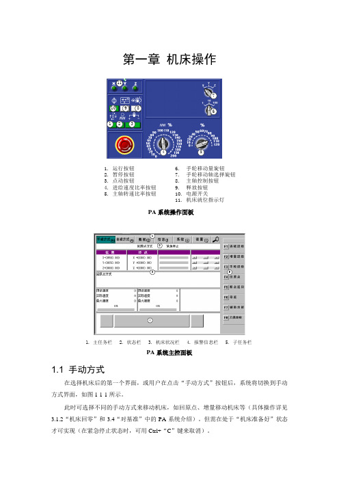
第一章机床操作213456 78910111. 运行按钮2. 暂停按钮3. 点动按钮4. 进给速度比率按钮5. 主轴转速比率按钮6. 手轮移动量旋钮7. 手轮移动轴选择旋钮8. 主轴控制按钮9. 释放按钮10. 电源开关11. 机床就位指示灯PA系统操作面板213451. 主任务栏2. 状态栏3. 机床状况栏4. 报警信息栏5. 子任务栏PA系统主控面板1.1 手动方式在选择机床后的第一个界面,或用户在点击“手动方式”按钮后,系统将切换到手动方式界面,如图1-1-1所示。
此时可选择不同的手动方式来移动机床,如回原点、增量移动机床等(具体操作详见3.1.2“机床回零”和3.4“对基准”中的PA系统介绍)。
但需在处于“机床准备好”状态才可实现(在紧急停止状态时,可用Ctrl+“C”键来取消)。
图1-1-1注:在进入PA系统后需进行两步最基本的操作:第一步需取消紧急停止状态(Ctrl + “C”),第二步就是将所有可移动轴回原点,否则不能进行任何其它手动操作和自动运行程序。
1.2 自动方式点击主任务栏中“自动方式”按钮后,系统切换到如1-2-1所示的界面。
在此界面下可以进行与工件加工程序有关的各种运行方式的选择。
状态栏中显示哪一个NC程序将要以何种方式运行。
位置栏中为机床当前位置,终点坐标为当前程序行中指定要移动到的位置。
图1-2-11.2.1 选择工件程序如果用户还没有选择需要运行的程序或者需要更换运行程序,则选择“选择工件程序”,进入图1-2-2的下一界面。
此时子任务栏有以下命令可供选择:图1-2-21)选择程序号:用“选择程序号”命令来选择将要执行的程序,此时界面如图1-2-3所示,程序列表及程序号为当前已调入到CNC存储器中的NC程序。
图1-2-32)选择程序段:用“选择程序段”命令来选择从现在程序的某一程序段开始运行。
如图1-2-4所示。
此时允许用户选择从当前程序中某一程序段开始执行,这使得继续执行中断的工件程序成为可能。
Pajek:学习讲义

多个颜色的网络图,鼠标放在某类节点边上按住左键拖动,即可拖动所有此类节点 还有多个命令,比如将两个partition进行合并
• 3.三种简化网络的方式:
抽取网络的一部分 Operations>Extract from Network>partition 注意:我们无法看到某个洲国家在全球的地位(因为subnetwork的顶点数和partition的 定点数不同) 有补救措施! 选择国际地位partition为第一partition,洲partition为第二,从第二个partition中抽取第 一个partition.DONE!
图中移除一个component • Operations>extract from network>partition 通过k-core的方式进行聚类 • Net>partitions>core>input/output/all 六、桥和中间人 概念解释 • .桥:是一条连线,移除该线可以增加网络中的组件个数 • 关键点cut-vertex:是一个顶点,移除该顶点可以增加网络中的组件个数 • 二组件bi-component:是一个组件,最小规模是3,并且不包括关键点 寻找bi-component、桥和关键点 Net>component>bi-component
• 2.以World_trade.paj为例进行演示
• • • • •
• •
对被选的图创建新的partition Partition>create Null Partition 在绘图板上操作小贴士: Shift键+鼠标点击vertex:class数值加1 Shift+鼠标不在vertex上点击:all class数值加1 alt键+鼠标点击vertex:class数值减1(如果class大于零) alt+鼠标不在vertex上点击:all class数值减1 (如果class大于零)
pajek中文使用手册

Andrej Mrvar Faculty of Social Sciences University of Ljubljana, Slovenia http://mrvar.fdv.uni-lj.si/ andrej.mrvar@fdv.uni-lj.si
目录
1.Pajek介绍 ....................................................................................................................................... 1 2.数据对象........................................................................................................................................ 3 3 主窗口工具栏...............................................................................................................................7
pajek使用手册
PajekProgram for Analysis and Visualization of Large Networks Reference ManualList of commands with short explanationversion1.10Vladimir Batagelj and Andrej Mrvar Ljubljana,October28,2005c 1996,2005V.Batagelj,A.Mrvar.Free for noncommercial use. PdfLaTex version October1,2003Vladimir BatageljDepartment of Mathematics,FMFUniversity of Ljubljana,Sloveniahttp://vlado.fmf.uni-lj.si/vladimir.batagelj@fmf.uni-lj.siAndrej MrvarFaculty of Social SciencesUniversity of Ljubljana,Sloveniahttp://mrvar.fdv.uni-lj.si/andrej.mrvar@fdv.uni-lj.siContents1Pajek3 2Data objects5 3Main Window Tools73.1File (7)3.2Net (11)3.3Nets (27)3.4Operations (29)3.5Partition (38)3.6Partitions (39)3.7Permutation (40)3.8Permutations (41)3.9Cluster (41)3.10Hierarchy (41)3.11Vector (41)3.12Vectors (42)3.13Options (43)3.14Info (46)3.15Tools (47)4Draw Window Tools494.1Main Window Draw Tool (49)4.2Layout (49)4.3Layers (51)4.4GraphOnly (52)4.5Previous (52)4.6Redraw (53)4.7Next (53)4.8Options (53)4.9Export (57)4.10Spin (59)4.11Move (59)4.12Info (60)5Exports to EPS/SVG/VRML615.1Defaults (61)5.2Parameters in EPS,SVG and VRML Defaults Window (61)5.3Exporting pictures to EPS/SVG–defining parameters in inputfile6516Using Macros in Pajek706.1What is a Macro? (70)6.2How to record a Macro? (70)6.3How to execute the Macro? (70)6.4Example (70)6.5Repeating last command (71)7Colors in Pajek73 8Citing Pajek752Pajek–Manual31PajekPajek is a program,for Windows,for analysis and visu-alization of large networks having some thousands or evenmillions of vertices.In Slovenian language the word pa-jek means spider.The latest version of Pajek is freelyavailable,for noncommercial use,at its home page: http://vlado.fmf.uni-lj.si/pub/networks/pajek/We started the development of Pajek in November1996.Pajek is im-plemented in Delphi(Pascal).Some procedures were contributed by Matjaˇz Za-verˇs nik.The main motivation for development of Pajek was the observation that there exist several sources of large networks that are already in machine-readable form.Pajek should provide tools for analysis and visualization of such net-works:collaboration networks,organic molecule in chemistry,protein-receptor interaction networks,genealogies,Internet networks,citation networks,diffusion (AIDS,news,innovations)networks,data-mining(2-mode networks),etc.See also collection of large networks at:http://vlado.fmf.uni-lj.si/pub/networks/data/The design of Pajek is based on our previous experiences gained in devel-opment of graph data structure and algorithms libraries Graph and X-graph,col-lection of network analysis and visualization programs STRAN,RelCalc,Draw, Energ,and SGML-based graph description markup language NetML.Figure1:Pajek/SpiderV.Batagelj and A.Mrvar Pajek1.10/October28,20054Pajek–ManualFigure2:Approaches to deal with large networks The main goals in the design of Pajek are:•to support abstraction by(recursive)decomposition of a large network into several smaller networks that can be treated further using more sophisticated methods;•to provide the user with some powerful visualization tools;•to implement a selection of efficient(subquadratic)algorithms for analysis of large networks.With Pajek we can:find clusters(components,neighbourhoods of‘impor-tant’vertices,cores,etc.)in a network,extract vertices that belong to the same clusters and show them separately,possibly with the parts of the context(detailed local view),shrink vertices in clusters and show relations among clusters(global view).Besides ordinary(directed,undirected,mixed)networks Pajek supports also multi-relational networks–2-mode networks(bipartite(valued)graphs–net-works between two disjoint sets of vertices),and temporal networks(dynamic graphs–networks changing over time).V.Batagelj and A.Mrvar Pajek1.10/October28,2005Pajek–Manual5 2Data objectsIn Pajek six types of objects are used:Figure3:Pajek’s Main Windowworks–main objects(vertices and lines).Default extension:.net.Network can be presented on inputfile in different ways:•using arcs/edges(e.g.12–line from1to2)•using arcslists/edgeslists(e.g.123–line from1to2and from1to3)•matrix format•UCINET,GEDCOM,chemical formats...Additional information for network drawing can be included in inputfile as well.This is explained in the section Exports to EPS/SVG/VRML.2.Partitions–they tell for each vertex to which class vertex belong.Defaultextension:.clu.3.Permutations–reordering of vertices.Default extension:.per.4.Clusters–subset of vertices(e.g.one class from partition).Default exten-sion:.cls.5.Hierarchies–hierarchically ordered vertices.Example:Rootg1g2g11g12v5,v6,v7v1,v2v3,v4V.Batagelj and A.Mrvar Pajek1.10/October28,20056Pajek–Manual Root has two subgroups–g1and g2.g2is a leaf–cluster with verticesv5,v6and v7.g1has two subgroups–g11and g12...Default extension: .hie.6.Vectors–they tell for each vertex some numerical property(real number).Default extension:.vec.By double clicking on selected network,partition,...you can show the object on screen.The procedures in Pajek’s main window(see Figure3)are organized accord-ing to the types of data objects they use as input.Permutations,partitions and vectors can be used to store properties of vertices measured in different scales:ordered,nominal(categorical)and numeric.Figure4:Spider web;Photo:Vladimir Batagelj.V.Batagelj and A.Mrvar Pajek1.10/October28,2005Pajek–Manual7 3Main Window Tools3.1FileInput/Output manipulation with the six data objects.•Network–N–Read network from Asciifile.–Edit network.Choose vertex,show its neighbors and then:∗add new lines to/from selected vertex(by left mouse double click-ing on Newline);∗delete lines(by left mouse double clicking);∗change value of line(by single right mouse clicking);∗subdivide line to two orthogonal lines using new invisible vertex(by single middle mouse clicking).–Save selected network to Asciifile.–Export Matrix to EPS–write matrix in EPS format:∗Original–using default numbering(for1-mode and2-mode net-works).∗Using Permutation–using current permutation.Additionallylines can be drawn to divide different classes defined by selectedpartition.Option can be used for1-mode and2-mode networks.∗Using Partition–using current partition.In the text windownumber and density of lines among classes(and vertices in se-lected two classes)are displayed.Additionally matrix is exportedto EPS where density is expressed using shadowing:1.Structural–Densities are normalized according to maxi-mum possible number of lines among classes(suitable fordense networks).2.Delta–Densities are normalized according to vertices havingthe highest number of input and output neighbors in classes(suitable for sparse networks).∗Only Black Borders–If checked all squares in matrix will haveblack borders,otherwise dark squares will have white and lightsquares will have black borders.–Change Label of selected network.–Dispose selected network from memory.V.Batagelj and A.Mrvar Pajek1.10/October28,20058Pajek–ManualTable1:List of time events.Event ExplanationTI t initial events–following events happen whentime point t startsTE t end events–following events happen whentime point t isfinishedAV vns add vertex v with label n and properties sHV v hide vertex vSV v show vertex vDV v delete vertex vAA uvs add arc(u,v)with properties sHA uv hide arc(u,v)SA uv show arc(u,v)DA uv delete arc(u,v)AE uvs add edge(u:v)with properties sHE uv hide edge(u:v)SE uv show edge(u:v)DE uv delete edge(u:v)CV vs change vertex property–change property of vertex v to sCA uvs change arc property–change property of arc(u,v)to sCE uvs change edge property–change property of edge(u:v)to sCT uv change type–change(un)directedness of line(u,v)CD uv change direction of arc(u,v)PE uvs replace pair of arcs(u,v)and(v,u)by single edge(u:v)with properties sAP uvs add pair of arcs(u,v)and(v,u)with properties sDP uv delete pair of arcs(u,v)and(v,u)EP uvs replace edge(u:v)by pair of arcs(u,v)and(v,u)with properties s•Time Events Network–N–Read Time Events–Read time network described using time events.See Table1.List of properties s can be empty as well.If several edges(arcs)canconnect two vertices,additional tag like:k(k-th line)must be given todetermine to which line the command mand HE:31437results in hiding the third edge connecting vertices14and37.Example of time network described using time events:*Vertices3*EventsTI1V.Batagelj and A.Mrvar Pajek1.10/October28,2005Pajek–Manual9AV2"b"TE3HV2TI4AV3"e"TI5AV1"a"TI6AE131TI7SV2AE121TE7DE12DV2TE8DE13TE10HV1TI12SV1TE14DV1See also other possibility:description of time network using time in-tervals.–Save–Save time network in time events format.•Partition–C–Read partition from Asciifile.–Edit partition(put vertices to classes).–Save selected partition to Asciifile.–Change Label of selected partition.–Dispose selected partition from memory.•Permutation–P–Read permutation from Asciifile.–Edit permutation(interchange positions of two vertices).–Save selected permutation to Asciifile.–Change Label of selected permutation.–Dispose selected permutation from memory.•Cluster–S(list of selected vertices)–Read cluster from Asciifile.V.Batagelj and A.Mrvar Pajek1.10/October28,200510Pajek–Manual–Edit cluster(add and delete vertices).–Save selected cluster to Asciifile.–Change Label of selected cluster.–Dispose selected cluster from memory.•Hierarchy–H–Read hierarchy from Asciifile.–Edit hierarchy(change types and names of nodes,or show vertices(and subtree)belonging to selected node).–Save selected hierarchy to Asciifile.–Change Label of selected hierarchy.–Dispose selected hierarchy from memory.•Vector–V–Read vector from Asciifile.–Edit vector(change components of vector).–Save selected vector(s)to Asciifile.If cluster representing vector id’sis present,all vectors with corresponding id numbers will be saved tothe same outputfile.Vector’s id can be added to cluster by pressingV on the selected vector(empty cluster should be createdfirst).Allvectors must have the same dimensions.–Change Label of selected vector.–Dispose selected vector from memory.•Pajek Project File–*.paj–Read Pajek projectfile(file containing all possible Pajek data ob-jects–networks,partitions,permutations,clusters,hierarchies andvectors).–Save all currently loaded objects as a Pajek projectfile.•Repeat session–During program execution all commands are written to file*.log.In this way you can repeat any execution by running selected logfile.If you change in the logfile a name of afile to?,program will ask for name when running logfile next time(so you can repeat the same sequence of steps–logfile with different input data).If startup logfile(Pa-jek.log)exists(in the same directory as Pajek.exe),it is automatically exe-cuted every time when Pajek is run.V.Batagelj and A.Mrvar Pajek1.10/October28,2005Pajek–Manual11•Show Report Window–Bring the report window in the front in the case that it was closed or is not visible.•Exit program.3.2NetOperations,for which only a network is needed as input.•Transform–Transpose–Transposed network of selected network:∗1-Mode-Change direction of arrows.∗2-Mode-Interchange Rows and Cols.–Remove∗all edges–Remove all edges from selected network.∗all arcs–Remove all arcs from selected network.∗multiple lines–Remove all multiple lines from selected network.1.Sum Values–Values of all deleted lines are added to notdeleted line between corresponding two vertices.2.Number of Lines–Value of line between two vertices in anew network correspond to the number of lines between thetwo vertices in original network.3.Min Value–Minimum value of all lines between two verticesis selected.4.Max Value–Maximum value of all lines between two ver-tices is selected.5.Single Line–Value of line between two vertices in a newnetwork is1.∗loops–Remove all loops from selected network.∗lines with value1.lower than–Remove all lines with value lower than specifiedvalue.2.higher than–Remove all lines with value higher than speci-fied value.3.within interval–Remove all lines with values within speci-fied interval.∗all arcs from each vertex exceptV.Batagelj and A.Mrvar Pajek1.10/October28,200512Pajek–Manual1.k with lowest line values–Sort lines around vertices in as-cending order according to output line values.Keep only se-lected number of lines with lowest values.2.k with highest line values–Sort lines around vertices indescending order according to output line values.Keep onlyselected number of lines with highest values.–Add additional vertices,lines or vertices/lines labels to network.∗Vertices–Copy network to new network.Dimension can be en-larged for selected number of vertices(additional vertices withoutlines are added).∗Source and Sink–If network is acyclic,add uniquefirst and lastvertex(new network has two artificial vertices).∗Sibling edges–Add sibling edges to vertices with a common1.Input–arc-ancestor2.Output–arc-descendant∗Vertices Labels from File–Change the default vertices labels(v1,v2...)with labels given in input networkfile.∗Line Labels as Line Values–replace labels of lines(or createnew if there are no)with line values.Number of decimal placesis the same as used in Draw window for marking lines with linevalues.–Edges→Arcs–Convert all edges to arcs(in both directions)(makedirected network).–Arcs→Edges∗All–Convert all arcs to edges(make undirected network).∗Bidirected only–Convert only arcs in both directions to edges:1.Sum Values–Value of the new edge is the sum of values ofboth arcs.2.Min Value–Value of the new edge is the smaller of valuesof arcs.3.Max Value–Value of the new edge is the larger of values ofarcs.–Line Values–Transformations of line values:∗Recode–Display frequency distribution of line values accordingto selected intervals and recode line values in this way.∗Multiply by a constant.V.Batagelj and A.Mrvar Pajek1.10/October28,2005Pajek–Manual13∗Add Constant to line values.∗Absolute line values.∗Absolute+Sqrt–square root of line values.∗Truncate–truncated line values.∗Exp–exponent of line values.∗Ln–natural logarithm of line values.∗Power–selected power of line values.∗Normalize1.Sum–normalize so that the sum of line values will be12.Max–normalize so that the maximum line value will be1–Reduction∗Degree–(Recursively)delete from network all vertices with de-gree lower than selected value(according to Input,Output or Alldegree).Operation can be limited to selected cluster.∗Hierarchical–Recursively delete from network all vertices thathave only0or1neighbor.Results:simpler network and hierarchywith deleted vertices.Original network can be later restored(if weforget directions of lines).∗Subdivisions–Recursively delete from network all vertices thathave exactly2neighbors(together with corresponding two lines)and(instead of that)add direct line between these two neighbors.Result is simpler network(for drawing).Original network cannotbe restored!∗Design(flow graph)Reduction of all structural parts of networkaccording to McCabe(for programs–flow graphs)[35].–Generate in Time–Generate network in specified time(s).Inputfirsttime,last time and step(integers).Additional parameters when vertices and lines are active should begiven in network to perform this operation.They must be given be-tween signs[and]:-is used to divide lower and upper limit of interval,,is used to separate intervals,*means infinity.Example:*Vertices31"a"[5-10,12-14]2"b"[1-3,7]3"e"[4-*]*EdgesV.Batagelj and A.Mrvar Pajek1.10/October28,200514Pajek–ManualFigure5:Part of Reuters Terror News network on the36th day.V.Batagelj and A.Mrvar Pajek1.10/October28,2005Pajek–Manual15121[7]131[6-8]Vertex’a’is active from times5to10,and12to14,vertex’b’in times1to3and in time7,vertex’e’from time4on.Line from1to2is ac-tive only in time7,line from1to3in times6to8.The lines and vertices in a temporal network should satisfy the consis-tency condition:if a line is active in time t then also its end-verticesare active in time t.When generating time slices of a given temporalnetwork only’consistent’lines are generated.Note that time records should always be written as last in the rowwhere vertices/lines are defined.See also other possibility of describing time network:description oftime network using time events.∗All–Generate all networks in specified times.∗Only Different–Generate network in specified time only if thenew network will differ in at least one vertex or line from the lastnetwork which was generated.–2-Mode to1-Mode–Generate an ordinary(1-mode)network from2-mode(affiliation)network.Result is a valued network.To storea2-mode network in inputfile use Pajek or Ucinet format(look atDavis.dat from Ucinet dataset).∗Rows–Result is a network with relations among row elements(actors).The value of line tells number of common events of thetwo actors.∗Columns–Result is network with relations among column ele-ments(events).The value of a line tells number of actors that tookpart in both events.∗Include Loops–If checked,loops with value telling the totalnumber of events for each actor(total number of actors for eachevent),are added.∗Multiple Lines–Generate nonvalued1-mode network,wheremultiple lines among vertices can exist.The label of the gen-erated line corresponds to the label of the event/actor that servedto induce the line.If partition of the same dimension is present,multirelational network can be generated.∗Normalize1-Mode–Normalize the obtained1-Mode network.1-Mode network must be obtained with option include loops checked,and multiple lines not checked:V.Batagelj and A.Mrvar Pajek1.10/October28,200516Pajek–ManualGeo ij=a ij √a ii a jjInputij =a ija jjOutputij =a ija iiMin ij=a ijmin(a ii,a jj)Max ij=a ij max(a ii,a jj)MinDir ij= a ija iia ii≤a jj 0otherwiseMaxDir ij= a ija jja ii≤a jj 0otherwiseThe obtained network is usually not sparse.To make it sparser useNet/Transform/Remove/lines with value/lower than–Multiple Relations∗Extract Relation(s)–Extract one or selected list of relationsfrom selected multiple relations network.∗Canonical Numbering–Enumerate relations with sequential num-bers1,2,...∗Line Values−>Relation Numbers–Store line values as rela-tion numbers(absolute truncated values).∗Relation Numbers−>Line Values–Store relation numbers asline values.∗Change Relation Number/Label–Change selected relationnumber to new relation number with corresponding label.–Sort Lines–∗Neighbors around Vertices–For each vertex sort lines con-nected to it in ascending order according to other end-vertex.∗Line Values–Sort lines in ascending or descending order accord-ing to line values.•Random Network–Generate random network of selected dimensionV.Batagelj and A.Mrvar Pajek1.10/October28,2005Pajek –Manual 17–Total No.of Arcs –Generate random directed network of selected dimension and given number of arcs.–Vertices Output Degree –Generate random directed network of se-lected dimension and output degree of each vertex in given range.–Erdos-Renyi –Generate undirected,directed,acyclic,bipartite or 2-mode random network according to model defined by Erdos and Renyi:each line is selected with the given probability p .Instead of p ,which is for large and sparse networks (very)small number,in Pajek a more intuitive average degree d is used.They are connected with relations d =1n v ∈V deg(v )=2m n and m =pM where n =|V |,m =|L |and M is the number of lines in maximal possible network –for example,for undirected graphs M =n (n −1).–Scale Free –Generate scale free undirected,directed or acyclic net-work.The procedure is based on a refinement of the model for gener-ating scale free network s,proposed in [40].At each step of the growth a new vertex and k edges are added to the network N .The endpoints of the edges are randomly selected among all vertices according to the probabilityPr (v )=αindeg (v )|E |+βoutdeg (v )|E |+γ1|V |where α+β+γ=1.It is easy to check that v ∈V Pr (v )=1.–Extended Model –Generate random network according to extended model defined by Albert and Barabasi [2].•Partitions –Partitioning Network.Result is a Partition.–Degree∗Input –Number of lines into vertices.∗Output –Number of lines out of vertices.∗All –Number of neighbors of vertices.–Domain –For each vertex compute its domain according to input ,output or all neighbors.Results are:∗Partition containing size of domain -number of reachable ver-tices.∗Vector containing the normalized size of domain -normalizationis done by total number of vertices –1.V .Batagelj and A.Mrvar Pajek 1.10/October 28,200518Pajek–Manual∗Vector containing the average distance from/to domain.Proximity Prestige index can be computed by dividing the normalizedsize of domain by average distance.–Core–k-core is a subnetwork of given network where each vertex hasat least k neighbors in the same core according to:∗Input...lines coming into vertex.∗Output...lines going out of vertex.∗All...all neighbors.∗2-Mode–core partition of a2-mode network.Given minimumdegree infirst(k1)and minimum degree in second subset(k2)a new partition is generated where0means that vertex does notbelong to the core of prespecified k1and k2,1means that vertexbelongs to that core.∗2-Mode Review–Given starting values of k1and k2the follow-ing list is computed:k1k2Rows Cols Compwhere k1is minimum degree in thefirst,k2minimum degree inthe second subset,Rows and Cols are number of vertices infirstand second subset respectivelly and Comp,number of connectedcomponents in network induced by k1and k2.k1and k2are in-cremented until the resulting network is empty.–Valued Core–Generalized k-core:Instead of counting lines(neigh-bors)use values of lines.sum of lines or maximum value can be usedwhen computing valued core:Sum valued core of threshold val is a subnetwork of given networkwhere the sum of values of lines to(from)the members of the samecore is at least val.Max valued core of threshold val is a subnetwork of given networkwhere the maximum value of all lines to(from)the members of thesame core is at least val.Threshold values must be given in advance.Two different ways todetermine thresholds:∗First Threshold and Step–Selectfirst threshold value and stepin which to increase threshold.∗Selected Thresholds–Thresholds(increasing numbers)are givenusing vector.Additionally,Input,Output or All valued cores can be used.–DepthV.Batagelj and A.Mrvar Pajek1.10/October28,2005Pajek–Manual19V.Batagelj and A.Mrvar Pajek1.10/October28,200520Pajek–Manual∗Acyclic Partition acyclic network according to depths of vertices.∗Genealogical Partition genealogy network according to layers ofvertices.–p-Cliques Partition network according to p-Cliques(partition to clus-ters where vertices have at least proportion p(number between0and1)neighbors inside the cluster.∗Strong...for directed network.∗Weak...for undirected network.–Vertex Labels–Partition vertices with same labels to the same classnumbers(for molecule).–Vertex Shapes–Partition vertices with same shapes(ellipse,box,dia-mond)to the same class numbers(used in genealogy to show gender).–Islands–Partition vertices of network with values on lines(weights)to cohesive clusters(weights inside clusters must be larger than weightsto neighborhood):the height of vertex(vector)is defined as the maxi-mum weight of the neighbor lines.Two options:∗Line Weights∗Line Weights[Simple]New network with only lines constituting islands can be generated ifGenerate Network with Islands is checked.–Bow-Tie–Partition vertices of directed network(graph structure ofthe web)to the following classes:1–LSCC,2–IN,3–OUT,4–TUBES,5–TENDRILS,0–OTHERS.–2-Mode–Partition of vertices of a2-mode network into two subsets.•Components–Strong–Strong Components of selected network.–Strong-Periodic–Strong Periodic Components of selected network-strongly connected components are further divided according to peri-ods.–Weak–Weak Components of selected network.–Bi-Components–Biconnected Components of selected network.Ar-ticulation points belong to several classes,so the result cannot bestored in partition–biconnected components are stored in hierarchy!Minimal number of vertices in components can be selected.Addition-ally,partition containing articulation points is produced:number of V.Batagelj and A.Mrvar Pajek1.10/October28,2005Pajek–Manual21Figure7:Bow-tie–Graph structure in the web[16]biconnected components to which each vertex belongs is given.Par-tition containing vertices belonging to exactly one bicomponent,ver-tices outside bicomponents and articulation points is also produced:vertices outside bicomponents get class zero,each bicomponent isnumbered consecutively(from1to number of bicomponents)and ar-ticulation points get class number9999998.•Hierarchical Decomposition–Clustering*–Hierarchical clustering procedure.Input is dissimilar-ity network(matrix),which can be obtained using Operations/Dissimilarityor read from inputfile.∗Run–Hierarchical clustering procedure.Result is hierarchy withnested clusters and dendrogram in EPS.∗Options–Select method for hierarchical clustering procedure(general,minimum,maximum,average,ward,squared ward).–Symmetric-Acyclic–Symmetric-Acyclic decomposition of network.Result is hierarchy with nested clusters[22].•NumberingV.Batagelj and A.Mrvar Pajek1.10/October28,200522Pajek–Manual–Depth First–Depthfirst numbering of selected network...∗Strong...taking directions of arcs into account.∗Weak...forget directions(or undirected network).–Breadth First–Breadthfirst numbering of selected network...∗Strong...taking directions of arcs into account.∗Weak...forget directions(or undirected network).–Reverse Cuthill-McKee–RCM numbering.See paper.–Core+Degree–Numbering in decreasing order according to all corepartition.Within the same core number vertices are ordered in de-creasing order according to number of neighbors which have the sameor higher core number.•Citation Weights–If a network represents citation network,weights of lines(citations)and vertices(articles)can be computed.Results are:–Network with values on lines representing importance of citations.–Binary partition with vertices on the main path.–Network containing only main path.–Vector with importance of vertices(articles).Different methods of assigning weights[30]:–Search Path Count(SPC)–pute from Source to Sink.–Search Path Link Count(SPLC)–method.Each vertex is consid-ered as Source.–Search Path Node Pair(SPNP)–method.Weights can also be normalized(usingflow or maximum value)or logged.•k-neighbors–Select all vertices–Input...from which we can reach selected vertex in at most k-steps.–Output...that can be reached from selected vertex in at most k-steps.–All...Input+Output(forget direction of lines)Result is partition where vertices are in class numbers equal to the dis-tance from given vertex,vertices that cannot be reached from selectedvertex are in class number9999998.After you have a partition youcan extract subnetwork.V.Batagelj and A.Mrvar Pajek1.10/October28,2005。
Parker PSD程序可配置快速入门指南说明书

Quick Start GuideAuthor: KW Version:V1.0Last change:9 November 2020Warranty DisclaimerWhile efforts were made to verify the accuracy of the information contained in this documentation, Parker expressly disclaims all warranties with regard to this application note, including, but not limited to, the implied warranties of merchantability and fitness of a particular purpose. Parker does not warrant, guarantee, or make any representation regarding the use or the results of the use of this application note in terms of correctness, accuracy, or reliability. The contents of this application note are subject to change without notice. Parker will publish updates and revisions of this document as needed. The documents supersedes all previous versions.Limitation of LiabilityYou agree that Parker shall not be liable to you under this agreement for any damages, including without limitation any lost profits, or any consequential, incidental, or punitive damages arising out of the use or inability to use this application note and related documents, or for any claim by another party. You agree and hold Parker harmless for all claims and damages from any third party as a result of their use or inability to use any product that you develop based on this application note and the products and/or services documented herein.Parker Hannifin Manufacturing Germany GmbH&Co.KGElectromechanical Automation EuropeBusiness Development & ApplicationsCopyright © 2010 - 2020All rights reserved.Table of contents1.DOWNLOADS AND INSTALLATION (3)2.ADJUST NET ADAPTER SETTINGS (5)3.PSD CONFIGURATION (5)4.CODESYS (7)5.EXAMPLE 1: POWER ON THE DRIVE AND DISPLAY THE STATUS VIA DIGITAL I/OS (9)6.EXAMPLE 2: USING OF PSD PROFIDRIVE STATEMACHINE FB (13)1. Downloads and Installation-Visit /psd_support-Download and unzip the PSD ServoManager (version >=01.09.01)-Use the link to CODESYS Store and download the CODESYS Development System -Download the PSD1 Programmable Target Package-Install the CODESYS Development System V3.5 32bit software (version >= 3.5.15.0) -Open CODESYS Development System-Open Package Manager-Install PSD Target-Select “PSD Target V1.x.package” file-Choose “Typical setup”-Press “Finish” when the setup is completed2. Adjust net adapter settings-Open Windows Control Panel -> Network connections -Adjust settings of network adapter:IP-Address: 192.168.10.xxxSub net mask: 255.255.0.03. PSD Configuration-Create a new PSD project-Start PSD net scan and select connected device-Device-> Device Identification -> Do PSD online device identification-Perform application specific settings: Device-> Device Settings-Select CODESYS execute path and start profileExecute path: C:\Program Files (x86)\CODESYS 3.5.15.40\CODESYS\Common\CODESYS.exeStart profile: C:\Program Files (x86)\CODESYS3.5.15.40\CODESYS\Profiles\CODESYSxx.xml-Perform complete axis configuration-Download the configuration4. CODESYS-Open CODESYS-Create a new standard project-Select PSD device-Select programming language-Open device communication settings-Scan network and select connected PSD device-Check or adjust the “MainTask” settings (Cycle type, cycle time and watchdog)-Now an empty project has been created and the communication between CODESYS and PSD is established.-Finally the user has to create an IEC program. In our Quick Start Guide we show two examples of how to control the PSD.5. Example 1: Power on the drive and display the status via digital I/Os Example task: Create IEC program (input0 = enable drive, output0 = status drive is enabled)1.Open PLC_PRG and insert an empty box from the ToolBox2.Click on and press F2 button to open the Input Assistant3.Select PSD_ReadDigitalInputs function block from the PSD1_PLC_Blocks library4.Declare the name of the block e.g. “ReadDigitalInputs”5.Assign the inputs and outputs of the block6.To select the Axis_Ref “F2” Input Assistant can be used7.Insert PSD_Power FB and PSD_WriteDigitalOutputs FB in the same way8. Login and download the program to the drive9. Start the program, CODESYS should show the [run] state and program can be monitored.10.Finally test the function and check the drive state, inputs and output status in optimizationwindow of PSD_ServoManager.6. Example 2: Using of PSD PROFIdrive StateMachine FBThe PROFIdrive statemachine is switched off for the programmable PSD and can be activated via PSD_PROFIDRIVE_SM function block!Example task: Create IEC program with PSD_PROFIDRIVE_SM function block and test with Siemens PLC and FB51.1.Open PLC_PRG and insert an empty box from the ToolBox2.Click on and press F2 button to open the Input Assistant3.Select PSD_PROFIDRIVE_SM function block from the PSD1_PLC_Blocks library4.Declare the name of the block e.g. “ProfiDriveSM”5.Assign the inputs and outputs of the block as in picture below6.The mapped Controlword [0x6040.00] has to be assigned to the Controlword Input of thePROFIdrive SM function block.e PG1_Status.SetStatusword1 to assign the Statusword Output from The PROFIdriveSM function block to the mapped Statusword 1 [0x6041.00].8.Adjust the cycle time. The callup should occur in a task cycle >=2ms.9.The communication between Siemens PLC and PSD can be established by following theFB51 user guide.10.Finally, the communication and PROFIdrive functionality can be tested by using the forcetable.。
pajek时间网络使用方法
pajek时间网络使用教程时间网络(temporal network)分为两种类型一种是Time Events,在某个时间点发生改变;另一种是time intervals,在某个时间段网络状态维持不变。
文件后缀。
tim。
文件显示时间网络以lin_rel4。
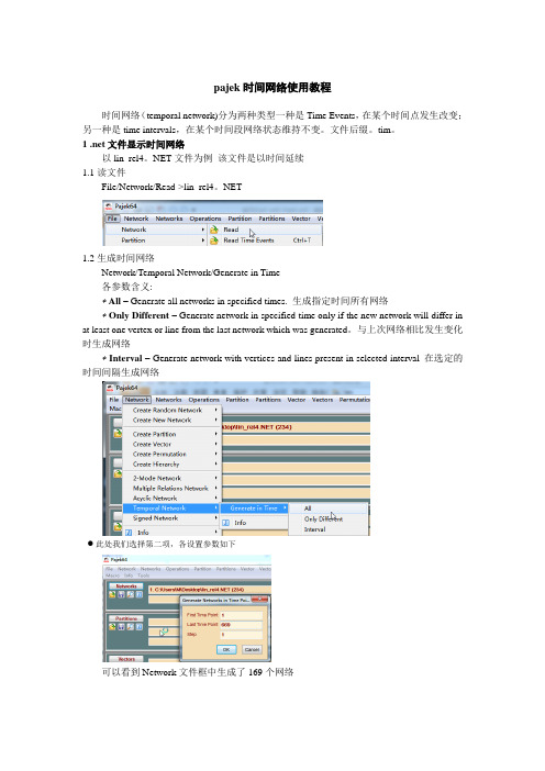
NET文件为例该文件是以时间延续1.1读文件File/Network/Read->lin_rel4。
NET1.2生成时间网络Network/Temporal Network/Generate in Time各参数含义:∗All – Generate all networks in specified times. 生成指定时间所有网络∗Only Different – Generate network in specified time only if the new network will differ in at least one vertex or line from the last network which was generated。
与上次网络相比发生变化时生成网络∗Interval – Generate network with vertices and lines present in selected interval 在选定的时间间隔生成网络此处我们选择第二项,各设置参数如下可以看到Network文件框中生成了169个网络每个网络就代表了该时刻网络的结构状态。
1.3绘制网络(1)选择从第二个网络开始(其实这是时间网络的初始网络),选择Draw/Network(2)点击Previous和Next可以动态绘制各时间节点的网络2.tim文件显示时间网络2.1读取时间文件File/Network/Read Time Events—>carlyle.tim2.2生成时间网络与1.2相同2.3绘制网络与1。
3相同参考文献:1 官网start with pajek教程http://mrvar。
酒店PA部完全标准操作程序手册

总则管家是酒店中一个非常重要的一线职能部门,它不仅负责酒店内绝大部分的清洁卫生,还为住店客人提供客房服务,管家部工作的质量和效率决定每位客人对酒店的评价关系到客房的营业成本。
管家部管理着酒店绝大部分的资产,设施及设备,如何能够使之发挥最大作用,减少损坏及维修的成本是管家房部一项重要的职责。
同时管家部还负责酒店公共区域的环境布置及装饰。
客人需要一个清洁、安全、舒适、方便的食宿场所,所以管家部还负责酒店公共酒店中扮演着一个重要的角色,它的成功可给客人留下贯穿始终的美好印象,这一美好印象会使客人再次回到我们的酒店,同是良好的口碑也会通过我们的客人传播出去,成为酒店最好的,可信度最高的广告宣传。
管家部实行经理负责制,对上向房务总监报告下分四个部分:客房中心、客房楼层、PA、洗衣房、部门内分四级管理:经理、主管、领班、员工。
第一节人事组织架构图(略)第二节工作目标我们的理想——使本酒店成为本地区最好、最完善、最卫生的星级酒店,拥有最高和服务水平,达到国际级的服务标准。
我们的态度——客人的满意就是我们的最终的工作目的。
我们的目标——保持整个酒店客房、楼层、公共区及办公区的清洁卫生,向客人提供恰当当的、礼貌的、完整的及最好的服务。
我们的希望——我们坚信对员工不断的培训有利于更快、更好地达到以上我们所确定的目标。
第三节管家部与其它部门的关系前厅部:提供新的房间状态、信息,以保证提高客房出租率。
协助前厅部行李生开门收取行李。
工程部:提供资料给工程部处理任何维修保养的事实。
餐饮部:收拾饮食餐具及餐车,协助房间餐饮。
财务部:协助做好固定资产的盘点,协助员工薪金支付。
人事部:对新员工的录用和培训计划,提供要求,并协助做好员工的培训工作。
保安部:提供资料以防止闲杂人员混进酒店,协助保安对酒店的区域做好防火防盗工作,以便设法处理。
市场营销部:协助它在客房、大堂内摆放广告宣传以便宣传推销酒店各种设施和服务。
采购部:管家部所需的一切用品由管家部提出来采购,明确采购物品的规格、质量、数量,核准后由采购部办理。
- 1、下载文档前请自行甄别文档内容的完整性,平台不提供额外的编辑、内容补充、找答案等附加服务。
- 2、"仅部分预览"的文档,不可在线预览部分如存在完整性等问题,可反馈申请退款(可完整预览的文档不适用该条件!)。
- 3、如文档侵犯您的权益,请联系客服反馈,我们会尽快为您处理(人工客服工作时间:9:00-18:30)。
1 引言
1.1 复杂网络的基本概念以及研究历史
近几年来,复杂网络的研究正处于蓬勃发展的阶段[1,2],其思想已经充斥到科学和社 会的每一个角落。复杂网络可以用来描述人与人之间的社会关系[3],物种之间的捕食关系 [4],计算机之间的网络联接[5],词与词之间的语义联系[6],科学家之间的合作关系[7],蛋 白质之间的相互作用 [8], 科研文章之间的引用关系[9] 以及网页的链接结构[9]等等。 总之, 从因特网到万维网, 从生物体的结构网络到动物之间的食物链, 从人体的神经网络到社会关 系网络等等,可以说,复杂网络,无处不在。复杂网络的研究正渗透到物理、生物甚至社会 学科等各个领域,因而,复杂网络的定性和定量研究已经成为当今科学的一大主题。 每一个系统中的复杂网络都有其自身的特殊性质, 有其紧密联系在一起的独特现象, 有 其自身的演化机制,但是不同的复杂网络在其结构特征上都呈现出一定的共性[10]。研究复 杂网络的共性,首先需要一种描述这种不同类型复杂网络的共同数学模型。 复杂网络模型的研究,最早可以追溯到十八世纪,由伟大的数学家欧拉建立。欧拉所研 究的问题,就是起源于当时俄国的一个小镇,这个小镇中有一些河流,在此镇中一共建了 7 座桥,小镇的人希望找到一条行走路线,能够通过所有的桥,并且每座桥只能经过一次。当 时人们反复尝试也没有找到这样的路线, 最后欧拉发现这样的路径是不存在的。 他分析这个 问题基本的手段, 就是把这个问题用一个抽象的图来表示。 具体做法即把这些河流分割开的 四个陆地区域,每一个区域用一个结点来表示,而把桥梁当成连接这些结点的连线。这样一 种图的表示方法,就演变成为表述复杂网络一种共同的模型。比如对 Internet 而言,每一个 结点表示一个路由器, 如果两个路由器之间直接通过光纤连接, 则这两个节点就通过一条边 相连。以人类社会关系网络而言,每一个人就可以看成一个结点,两个人如果是朋友关系, 那么这两个人之间就有一条边直接相连。因此,尽管复杂网络的类型是千差万别的,但是它 们都可以用共同的模型——图描述出来[11]。 一般来说,图的分类有两种方法。根据图中的边是否具有方向性,可以将图分为有向图 和无向图两种。实际上,当我们忽略边的方向的时候,或者反过来看认为任何一条边都是双 向的时候,有向图就成为无向图。因此,关于无向图的所有性质都可以在有向图中研究。另 外,根据图中是否考虑各条边的权重,可以将它分为有权图和无权图。同样地,如果将有权 图的各边权值都设为 1,有权图就称为无权图。因此,关于无权图的所有性质也可以在有权
2
2 Pajek 的主要特点
简单的说,Pajek 的特点主要表现在三个方面。在本章的三小节中将一一简单介绍。
1.2 Pajek 的产生背景
与一般计算机图的结构相比, 复杂网络的复杂性最主要表现在节点数目庞大, 通常达到 几千甚至几万个。比如,一个大型的家谱图,它的节点数(即人数)可以达到一万个。另外, 一个高分子的结构图中,通常也包含几千个原子。因此,复杂网络的结构比一般的计算机图 的结构要复杂得多。目前,虽然已经存在不少算法来对复杂网络的这种拓扑结构进行分析, 但它们通常都是基于复杂网络的矩阵表达形式, 因而非常耗时耗空间, 它们仅仅适用于中等 规模(即节点数为几百)的网络。因此,当务之急就是需要一种快速有效的软件来分析和仿 真复杂网络。Pajek 就是这样一种软件[13]。 Pajek 在斯拉夫语中表示的意思是“蜘蛛” 。众所周知,蜘蛛是生物中的织网高手,它编 织网络的能力令人叹为观止。而 Pajek 这个软件不仅为用户提供了一整套快速有效的用来分 析复杂网络的算法, 而且还提供了一个可视化的界面。 让用户可以从视觉的角度更加直观地 了解复杂网络的结构特性。 接下来的几个章节,第二章简单介绍了 Pajek 功能的三个主要特点;第三章中初步介绍 了 Pajek 的六种数据类型;第四章到第七章将结合复杂网络的拓扑结构特点详细分析 Pajek 的功能,并且给出具体的应用实例;第八章讨论了 Pajek 的可视化特点,从视觉的角度分析 复杂网络图的结构;第九章介绍了 Pajek 中宏文件的应用。
复杂网络仿真平台
摘要
复杂网络的概念已经在计算机、 生物、 物理以及社会科学等各个领域中得到广泛的应用。 尽管复杂网络的类型举不胜举,但是所有的复杂网络都可以用共同的模型——图来描述。 Pajek 以网络图的模型为基础,以六种数据类型为形式,以其快速有效性和人性化的特点, 为复杂网络的分析提供了一个仿真平台。 它集成了一系列快速有效的算法用于分析复杂网络 的拓扑结构, 包括从局部的角度分析网络节点和边的性质、 利用抽象化的手段分析网络的全 局结构、实现各种类型网络图之间的相互转换以及随即图的生成等。Pajek 利用一个三维的 可视化界面, 为用户提供了一系列可视化工具。 允许用户通过手动或者自动的调节节点位置、 旋转网络图等方法,从视觉的角度直观地分析网络模型。此外,Pajek 中的宏文件允许用户 将一系列常用的操作保存为一个文件, 从而能够有效地满足各种类型用户的不同需求。 本文 将结合具体的实例,分章节讨论 Pajek 在分析复杂网络拓扑结构中的应用。
6.4.1 1-模与 2-模复杂网络的概念 28 6.4.2 利用 Pajek 实现 2-模到 1-模复杂网络的转换 30 6.4.3 其他附属选项 31 7 利用 Pajek 生成复杂网络 34 7.1 生成复杂网络 34 7.2 生成 ER 随机网络 35 7.3 生成无尺度(scale-free)复杂网络 35 8 Pajek 的可视化 37 8.1 复杂网络图的绘制 37 8.1.1 绘制复杂网络图 37 8.1.2 绘制不同类节点的复杂网络图 37 8.1.3 绘制不同大小节点的复杂网络图 38 8.1.4 绘制不同权值的边的复杂网络图 38 8.2 调整复杂网络图的布局 38 8.3 复杂网络图的旋转 41 9 Pajek 中的宏 42 9.1 宏的作用 42 9.2 宏的定义 42 9.3 宏的使用 42 9.4 宏的应用实例 42 10 结论 44
1
图中研究。 利用图对复杂网络建模后,可以看到其结构具有很多相同的共性。例如关于顶点度值、 聚类系数、平均路径长度[12]的分析方法以及大量不同复杂网络中存在的相同的统计特征, 再如随机去点与选择性攻击对复杂网络结构的影响及其分析方法[10]。研究复杂网络的几何 性质,复杂网络的形成机制,复杂网络演化的统计规律,复杂网络上的模型性质,以及复杂 网络的结构稳定性,并把它与具体系统结合起来就是复杂网络研究的中心内容。
used sequence of elementary operations as a macro and run it as a single command. Using systems of macros, Pajek is adapted to special groups of users. In this article, with some typical examples, the main applications of Pajek are discussed to analysis the topology of complex networks.
关键词:复杂网络,可视化,抽象化,有向图,无向图,权值
EMULATOR OF COMPLEX NETWORK
ABSTRACT
The idea of complex network, with thousands of vertices and lines, have been widely applied in many different areas, including computer, biology, physics and social science, to name but a few. Although the types of complex networks are innumerable, all of them can be described by a common model, which is known as graph. Based on graphs and using six data structures, Pajek, which is very efficient and humanized, is a program designed for the emulation of complex network. The basic set of efficient algorithms are implemented in it to analyze the topology of complex networks, including analysis of the local nature of vertices and lines, abstraction to get a global view of network, transformation between different types of networks, generating random networks and so on. Pajek provide the user with some powerful visualization tools on a three-dimensioned reference frame. The user can further improve the picture manually or automatically by moving vertices or spin. Moreover, we can dlex network, visualization, abstraction, directed network, undirected network, weight
目
录
1 引言 1 1.1 复杂网络的基本概念以及研究历史 1 1.2 Pajek 的产生背景 2 2 Pajek 的主要特点 3 2.1 计算的快速性 3 2.2 可视化 4 2.3 抽象化 4 3 Pajek 的数据结构 6 3.1 Network(网络) 6 3.2 Partition(分类) 9 3.3 Permutation(排序) 9 3.4 Cluster(类) 10 3.5 Hierarchy(层次) 10 3.6 Vector(向量) 10 4 利用 Pajek 分析复杂网络基本性质 12 4.1 度的计算 12 4.2 两点间的距离 13 4.2.1 两点间的最短路径 13 4.2.2 复杂网络的直径 15 4.2.3 K 步之内的路径 15 4.2.4 复杂网络的测地矩阵(Geometric Matrices) 15 4.3k 近邻(k-neighbors) 16 4.4 聚类系数 17 4.4.1 CC1 --- 聚类系数 17 4.4.2 CC --- 2 近邻聚类系数 19 2 5 利用 Pajek 分析复杂网络结构 20 5.1 复杂网络图的遍历 20 5.1.1 深度优先搜索遍历 20 5.1.2 广度优先搜索遍历 21 5.2 复杂网络图的核心(Core) 21 5.3 复杂网络图的连通分量(components) 23 5.4 复杂网络的关键路径 24 6 利用 Pajek 转换复杂网络 26 6.1 无向边与有向边的转换 26 6.1.1 有向边转换为无向边 26 6.1.2 无向边转换为有向边 26 6.2 改变复杂网络图的结构 26 6.2.1 添加节点 26 6.2.2 添加兄弟边(sibling edges) 27 6.2.3 删除边 27 6.3 复杂网络图的缩减 27 6.4 2-模到 1-模网络图的转换 28