微型轴型增量编码器EB38A
宜科编码器
编码器型号:编码器EB38A/B 编码器EB38F/FX 编码器EB48P 编码器EBY48P 编码器EB50A 编码器EB50B 编码器EB50P 编码器EB58A/D 编码器EB58B/C 编码器EB58M 编码器EB58P 编码器EB58Q/K 编码器EB58H/W 编码器EB58FP 编码器EB58FH/FW 编码器EB58FK/FQ 编码器EB100P 编码器EB100RP 编码器EC40A/B/C 编码器EC40D/E 编码器EC40F/H 编码器EC40G/K 编码器EC58A/B/C 编码器EC58D 编码器EC58P 编码器EC58W/H 编码器EC58K/Q 编码器ECD58C 编码器EC100(R)P 编码器EC100(R)K 编码器EC100(R)R 编码器EC100(R)H 编码器ECY100P 编码器EC120(R)P 编码器EC120(R)K 编码器EC120(R)R 编码器EC120(R)H 编码器EC150(R)P 产品名称编码编码器EC150(R)K 编码器EC150(R)R 编码器EC150(R)H 编码器EV90A 编码器EVD90A 编码器EVR90A 编码器EV115A 编码器EVD115A 编码器EVR115A 编码器EV88P 编码器EV88R 编码器EV100P 编码器EV100K 编码器EV100R 编码器EV100H 编码器EVD100R 编码器ESS58P 编码器ESS58P-W 编码器EXI ST80A 编码器EXI AL80A 编码器EAX ST80A 编码器EAX AL80A 编码器ET58A/D 编码器ET58B/C 编码器ET58P/H 编码器ET58K 编码器ET58Q/W 编码器ECT58A/D 编码器ECT58B/C 编码器ECT58P/H 编码器ECT58K 编码器ECT58Q/W 编码器EAB50A/B 编码器EAC58A-E 编码器EAC58P 编码器EAC58Q/K 编码器EAC58W/H 编码器EAD58A 编码器EAC90A 编码器EAC115A 编码器EAS58B/C 编码器CAC58B/C 产品名称编码编码器EAM58A/D/E/L 编码器EAM58B/C 编码器EAM58G/F 编码器PAM58A-E 编码器PAM58G/F 编码器PAM58L 编码器PAM90A 编码器PAM115A 编码器EAM90A 编码器EAM115A 编码器HV115A 编码器HV115R编码器EB38A6-H4AR-2500 编码器EB38A/B 编码器EB38F/FX 编码器EB48P 编码器EBY48P 编码器EB50A 编码器EB50B 编码器EB50P 编码器EB58A/D 编码器EB58B/C 编码器EB58M 编码器EB58P 编码器EB58Q/K 编码器EB58H/W 编码器EB58FP 编码器EB58FH/FW 编码器EB58FK/FQ 编码器EB100P 编码器EB100RP 编码器EC40A/B/C 编码器EC40D/E 编码器EC40F/H 编码器EC40G/K 编码器EC58A/B/C 编码器EC58D 编码器EC58P 编码器EC58W/H 编码器EC58K/Q 编码器ECD58C 编码器EC100(R)P 编码器EC100 (R)K 编码器EC100(R)R 编码器EC100(R)H 编码器ECY100P 编码器EC120 (R)P 编码器EC120(R)K 编码器EC120(R)R 编码器EC120(R)H 编码器EC150 (R)P 产品名称编码编码器EC150(R)K 编码器EC150(R)R 编码器EC150(R)H 编码器EV90A 编码器EVD90A 编码器EVR90A 编码器EV115A 编码器EVD115A 编码器EVR115A 编码器EV88P 编码器EV88R 编码器EV100P 编码器EV100K 编码器EV100R 编码器EV100H 编码器EVD100R 编码器ESS58P 编码器ESS58P-W 编码器EXI ST80A 编码器EXI AL80A 编码器EAX ST80A 编码器EAX AL80A 编码器ET58A/D 编码器ET58B/C 编码器ET58P/H 编码器ET58K 编码器ET58Q/W 编码器ECT58A/D 编码器ECT58B/C 编码器ECT58P/H 编码器ECT58K 编码器ECT58Q/W 编码器EAB50A/B 编码器EAC58A-E 编码器EAC58P 编码器EAC58Q/K 编码器EAC58W/H 编码器EAD58A 编码器EAC90A 编码器EAC115A 编码器EAS58B/C 编码器CAC58B/C 产品名称编码编码器EAM58A/D/E/L 编码器EAM58B/C 编码器EAM58G/F 编码器PAM58A-E 编码器PAM58G/F 编码器PAM58L 编码器PAM90A 编码器PAM115A 编码器EAM90A 编码器EAM115A 编码器HV115A 编码器HV115R 高防开关MV115A11+1500 高防护开关MV115R16Z+840 分配隔离器EMA-L5/H6 分配隔离器EMA-L5/H6/L5 分配器EMB-L5/H6 拉线盒KD2000A 拉线盒SD2000A 拉线盒MD5000A 拉线盒MD8000A 拉线盒LD10000A 拉线盒LD15000A编码器工作原理:由一个中心有轴的光电码盘,其上有环形通、暗的刻线,有光电发射和接收器件读取,获得四组正弦波信号组合成A、B、C、D,每个正弦波相差90度相位差(相对于一个周波为360度),将C、D信号反向,叠加在A、B两相上,可增强稳定信号;另每转输出一个Z 相脉冲以代表零位参考位。
编码器种类
编码器种类
(一)高精度编码器
1绝对式轴角编码器型号—E1032-14
2绝对式轴角编码器型号—E3032-14
3绝对式轴角编码器型号—E1035-14
4绝对式轴角编码器型号—E1050-14
5绝对式轴角编码器型号—E1065-14
6绝对式轴角编码器型号—E1065-16
7绝对式轴角编码器型号—E3080A(1:16) 8绝对式轴角编码器型号—E3080A(1:16) 9绝对式轴角编码器型号—E1130K-16
10绝对式轴角编码器型号—E1130K-14
11绝对式轴角编码器型号—E1210-21
12绝对式轴角编码器型号—E1300-22
13增量式编码器型号—E2120
14增量式编码器型号—E2180
(二)普通编码器
1普通编码器—— PIE系列
2普通编码器—— PIE3系列
3普通编码器—— PIF系列
4普通编码器—— PID系列
5普通编码器—— PIB系列
6普通编码器—— PIG系列
7普通编码器—— PKT170系列
8普通编码器—— PKT130系列
9普通编码器—— PKT120系列
10普通编码器—— PKT100系列
11普通编码器—— PKT75系列
12普通编码器—— PKT50系列
13普通编码器—— PAL系列。
EnDat2.2_位置编码器双向数字接口
其作为传输时间。消除计算传输时间过程 中的不稳定因素,必须执行这个测量过程 三次以上并测试测量值的一致性。用较低 时钟频率测量信号传输时间(100 kHz至
200 kHz)。为达到足够高精度,位置值采 样的内部频率必须是数据传输时钟频率的 八倍以上。
给编码器的时 钟脉冲频率
编码器端的时 钟脉冲频率
编码器端数据 后续电子设备 端数据 开始计数
量式编码器 • EnDat接收芯片和标准部件简化了后续电
子设备 • 由于无需遥控传感信号,因此供电电源更
简单也更经济
• 连接技术简单:采用标准连接件(M12,
8针),标准单屏蔽电缆并且电缆接线成 本低 • 连接件小,因此适用于小型电机或减小系 统尺寸
• 无需任何昂贵的附加传感分析功能和接
线:EnDat 2.2发送附加信息(限位开关/ 温度/加速度)
4
2T
模式指令
时钟频率100 kHz至200 kHz 2T
模式 000111
0 0011 1
S F1 D
D D D CRC CRC CRC CRC CRC
S F1 D
D D D CRC CRC CRC CRC CRC
tD
S = 开始,F1 = 出错,D = 数据
选择传输类型
传输的数据类型分为位置值,位置值及附 加信息或参数。发送的信息类型由模式指 令选择。模式指令决定被传输信息的类 型。每个模式指令包括三个Bit。为确保信 息发送可靠,每个Bit均采用冗余发送(反 相或冗余)。如果编码器检测到不正确的 模式传输,将发送一个出错信息。EnDat 2.2还能在传输位置值的同时在附加信息中 传输参数值。因此它能保证当前位置值始 终提供给控制环,甚至包括请求参数时。
GE2000系列总线式交流伺服驱动单元使用手册(2012年7月第1版)--2012-07-11定稿
■接线 z 参加接线与检查的人员必须是具有相应能力的专业人员 z 产品必须可靠接地,接地电阻不应大于0.1Ω,不能使用中性线(零线)代替地线 z 接线必须正确、牢固,以免导致产品故障或意想不到的后果 z 与产品连接的浪涌吸收二极管必须按规定方向连接,否则会损坏产品 z 插拔插头或打开产品机箱前,必须切断产品电源
责。
VII
GE2000 系列总线式交流伺服驱动单元 使用手册
本手册为最终用户收藏。 诚挚的感谢您在使用广州数控设备有限公司的产品时, 对本公司友好的支持!
VIII
目录
目录
第一章 概 述 .........................................................................................................................1 1.1 产品简介...............................................................................................................1 1.2 基础知识...............................................................................................................2 1.3 到货检查...............................................................................................................6 1.4 产品外观...............................................................................................................9
SSAG系列
单侧·两侧弹回型
SSAG系列
长工作寿命弹回型,可满足向薄小型化发展的需求。
主要规格
项目 最大额定/最小额定(电阻负荷) 接触电阻(初期/寿命后) 动作力 操作寿命
规格
10mA 5V DC/50BA 3V DC
200mΩ max./500mΩmax.
1N(弹回), 1.5N(锁定侧) 100,000cycles(弹回) 30,000cycles(锁定侧)
1-2
¡
¡
¡
¡
¡
1-3
¡
¡
¡
¡
¡
电
1-4
路
接
2-2
点
数
2-3
¡
¡
¡
¡
¡
¡
2-4
¡
4-2
页
132
134
136
139
141
144
147
● 滑动开关焊接条件 ʜʜʜʜʜʜʜʜʜʜʜʜʜʜʜʜʜʜʜʜʜʜʜʜʜʜʜʜʜʜʜʜʜʜʜʜʜʜʜʜʜʜ175 ● 滑动开关使用时的注意事项 ʜʜʜʜʜʜʜʜʜʜʜʜʜʜʜʜʜʜʜʜʜʜʜʜʜʜʜʜʜʜʜʜʜʜʜʜʜʜ176
预热
D max.
E max.
A max. B C
Time (s)
˞
20 max.
F
小型通用 大型通用 其他
系列(回流型)
Vertical 1-pole, 3-positions
Horizontal SSSS2
Vertical
1-pole, 2-positions 1-pole, 2-positions
136
滑动开关
单侧·两侧弹回型 SSAG系列
SEW电机中文操作手册(精品)
操作手册–交流电机 DR/DV/DT/DTE/DVE ,异步伺服电机 CT/CV32安全提示..............................................................................................................53电机构造..............................................................................................................63.1交流电机的构造原理..................................................................................63.2铭牌,额定数据.........................................................................................74机械安装..............................................................................................................94.1开始安装之前............................................................................................94.2准备工作....................................................................................................94.3安装电机..................................................................................................104.4安装公差..................................................................................................115电器安装............................................................................................................125.1接线提示..................................................................................................125.2使用变频器运行时的特别注意事项..........................................................125.3有关单相电机的特别注意事项.................................................................125.4改善接地(EMV )...................................................................................135.5力矩电机和低速电机的特别注意事项......................................................135.6开关操作的特别注意事项........................................................................145.7运行过程中的环境条件............................................................................145.8电机连接..................................................................................................155.956 和 63 电机连线的准备工作.................................................................165.10DT56~ +/BMG 电机连接.........................................................................165.11ET56 单相电机设计.................................................................................175.12通过 IS 插头连接电机..............................................................................175.13通过 AB.., AD.., AM.., AS 插头连接电机.................................................215.14通过 ASK1 插头连接电机........................................................................215.15制动器连接..............................................................................................235.16辅助装备..................................................................................................246调试...................................................................................................................286.1调试的条件..............................................................................................286.2改变配有逆止器的电机的锁死方向..........................................................297运转故障............................................................................................................317.1电机上的故障..........................................................................................317.2制动器上的故障.......................................................................................327.3配变频器运转时的故障............................................................................328检查/维护.........................................................................................................338.1检查与维护周期.......................................................................................338.2电机和制动器维护的准备工作.................................................................348.3电机的检查/维护作业.............................................................................378.4制动器 BMG02 的检查/维护作业...........................................................398.5制动器 BR03 的检查/维护作业..............................................................408.6制动器 BMG05~8, BM15~62 的检查/维护作业......................................448.7制动器 BMG61/122 的检查/维护作业....................................................499技术参数............................................................................................................529.1BMG02制动器的制动力矩及需要维护前的做功......................................529.2BMG02 备件订货说明.............................................................................529.3BMG05~8, BR03, BC, Bd 制动器的做功、工作气隙及制动力矩.............539.4BM15~62 制动器的做功、工作气隙及制动力矩......................................549.5运行电流..................................................................................................559.6允许的球轴承型号...................................................................................599.7SEW 电机球轴承的润滑剂表...................................................................5910附录...................................................................................................................6010.1变更索引..................................................................................................6010.2关键词目录. (61)4操作手册 – 交流电机 DR/DV/DT/DTE/DVE ,异步伺服电机 CT/CV1重要提示安全提示和警告提示请务必注意本操作手册中的安全提示和警告提示!在保修期间,未按本操作说明操作而引起的故障,由使用者承担。
瑞普REP增量型旋转编码器ZSP4006系列产品手册
尺寸单位为毫米,若无特别说明,尺寸公差为± 0.5mm
Dimensions in mm. Unless otherwise stated, tolerance: ± 0.5mm
备注/Note *1 最大响应频率受限于最大转速
Max. response frequency is gated by max. rotation speed
◆ 输出波形 Output Waveform
◆ 接线表
Connection Table
接线颜色
绿 白 黄 红 黑 屏蔽线 棕 灰 橙
Color of Lead Wire
ZSP4006
2或3通道实心轴增量式编码器 / 2 or 3 Channel Solid-Shaft Incremental Encoder
◆ 产品特点 ● 体积小、重量轻、安装方便 ● 2路正交输出信号 (A,B)+零位信号 ● 外径40mm,轴径6mm
◆ Features ● Miniature size, easy assembling ● 2 quadrature output channel (A&B)+index signal ● Housing size 40mm, shaft dia. 6mm
◆ 技术参数 Technical Specifications
参数/Parameter 电源电压/supply Voltage 最大响应频率/Max. Response Frequency 最大转速/Max. Rotation Speed (*1) 最大消耗电流/Max. Current Consumption 最大上升-下降时间/Max. Rise-Fall Time 最大上升-下降时间/Max. Rise-Fall Time 工作温度/Operating Temperature 储存温度/Storage Temperature 防护等级/IP Rating
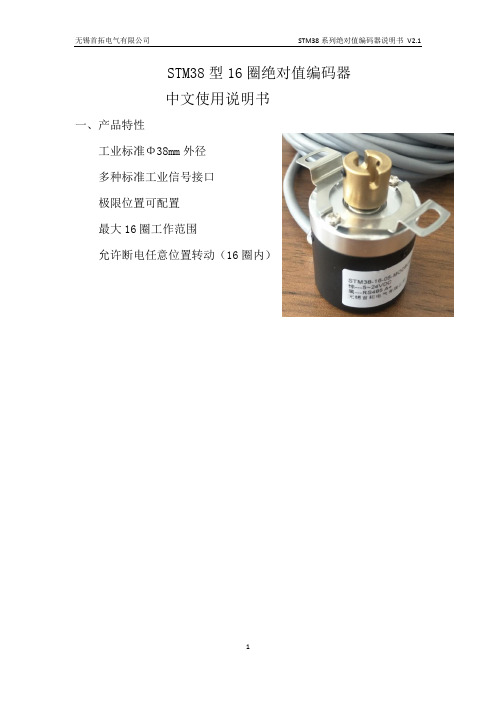
STM38 系列绝对值编码器说明书
STM38型16圈绝对值编码器中文使用说明书一、产品特性工业标准Φ38mm外径多种标准工业信号接口极限位置可配置最大16圈工作范围允许断电任意位置转动(16圈内)二、产品尺寸a:半中空轴输出b、实心轴输出三、参数规格四、命名规则和线定义1、引出线的颜色定义棕• VDD绿• GND黑• RS485• 输出A• 白• RS485• 输出B•五、通讯协议1)编码器工作模式:从机模式。
当编码器工作于从机模式时,外部设备(如单片机、PC机或PLC设备等,后文统称为外部设备)发送读取命令,编码器回复当前数值。
2)编码器和外部设备采用RS485标准的数据链路层传输数据,数据通讯格式为:19200bit/s;数据位8位、停止位1位、无奇偶校验位。
3)编码器对外部设备发送的错误数据帧,或者检测出通讯数据出现错误,编码器均不进行任何应答标准MODBUS RTU从机,通讯数据帧结构如下:5.1 主机读取编码器数值格式主机发送读命令编码器回复读命令5.2 主机修改编码器站号数据格式主机发送写命令编码器回复写命令编码器位置数据地址为0站号址为1实例:读取读取站号1的编码器数据:主机发送: 01 03 00 00 00 01 84 0A 84 0A为校验码CRC1 CRC2编码器回复:01 03 02 3D 26 CRC1 CRC2说明回复编码器位置为3D26 转换十进制为15654 --编码器的当前位置将站号1的编码器改为站号2:主机发送: 01 06 00 01 00 02 59 CB 59 CB为校验码CRC1 CRC2编码器回复:01 06 00 01 00 02 CRC1 CRC2备注:回复回来的编码器数据是十六进制数据,需要转换成10进制,才是编码六、使用环境·不得在具有点火性、爆发性气体的环境下使用。
·请勿在有化学品飞溅的场所中进行使用或保存,否则可能因内部回路断线或短路引起破损、烧毁。
·请不要让负载短路,否则会发生破裂或烧坏的可能。
汇川EA38H8编码器参数定义
汇川EA38H8编码器参数定义
汇川伺服电机编码器这个基本的功能与普通编码器是一样的,比如型的有A,A反,B,B反,Z,Z反等信号,除此之外,汇川伺服电机编码器还有着跟普通编码器不同的地方,那就是伺服电机多数为同步电机,同步电机启动的时候需要知道转子的磁极位置,这样才能够大力矩启动伺服电机,这样需要另外配几路信号来检测转子的当前位置,比如增量型的就有UVW等信号,正因为有了这几路检测转子位置的信号,汇川伺服电机编码器显得有点复杂了,以致一般人弄不懂它的道理了,加上有些厂家故意掩遮一些信号,相关的资料不,就更加增添了汇川伺服电机编码器的神秘色彩。
定义参数:
汇川编码器EA35H8-B20-5TH5N3A
川伺服编码器E135E9-2500-4P3D5N3TS2Q
汇川伺服编码器E135E9-2500-4P3D5N3TS2Q
全新汇川伺服编码器E135H8-2500-5P3D5N3TSQ
伺服电机编码器EA35H8-B20-5TH5N3A全新原装编码器
全新汇川伺服编码器E135H8-2500-5P3D5N3TSQ
EA38H8-B23-TH5N3 现货汇川编码器
扩展资料关于清零:
1、用一个直流电源给电机的UV绕组通以小于额定电流的直流电,U入,V出,将电机轴定向至一个平衡位置;
2、用示波器观察绝对编码器的最高计数位电平信号;
3、调整编码器转轴与电机轴的相对位置;
4、一边调整,一边观察最高计数位信号的跳变沿,直到跳变沿准确出现在电机轴的定向平衡位置处,锁定编码器与电机的相对位置关系;
5、来回扭转电机轴,撒手后,若电机轴每次自由回复到平衡位置时,跳变沿都能准确复现,则调零有效。
内策尔容栅编码器参数
内策尔(Netzer)容栅编码器是一种用于精确测量旋转轴位置的设备,它通过电容感应原理来实现非接触式的位置检测。
以下是一些关于内策尔容栅编码器的主要参数:
1. 产品型号:内策尔提供多种型号的容栅编码器,如DS25、DS37、DS58、DS70、DS90和DS130等,以满足不同应用场景的需求。
2. 外径尺寸:这些编码器的外径范围从16mm到300mm不等,适用于各种不同的机械尺寸和空间限制。
3. 分辨率:分辨率是指编码器能够区分的最小角度变化,这通常取决于编码器的设计和内部结构。
4. 工作温度:编码器能够在一定的温度范围内正常工作,这个范围定义了其适用的环境条件。
5. 输出接口:编码器可能提供多种输出接口,如模拟信号、数字信号、SSI或SPI等,以便于与不同的控制系统连接。
6. 电源电压:编码器工作时所需的电源电压范围。
7. 最大转速:编码器能够承受的最大旋转速度,超过此速度可能会影响其性能或损坏设备。
8. 防护等级:编码器的防尘防水等级,如IP65或IP67,表示其对环境条件的适应能力。
A38S磁旋转编码器说明书
F.G(屏蔽线)
控制输出线路图
推拉输出 编码器内部电路
外部连接
NPN 集电极开路输出 编码器内部电路 外部连接
电压输出 编码器内部电路
外部连接
长线驱动输出 编码器内部电路
外部连接
输出波形
推拉输出/NPN 集电极开路输出/电压输出
长线驱动输出
IBB 埃伯格
尺寸图
使用注意事项
512: 5‐12V±5% 524: 5‐24V±5%
规格/性能
电气性能
控制输出
Байду номын сангаас
集电极开路
负载电流:30mA 以下,残留电压:0.4V 以下
电压输出
负载电流:10mA 以下,残留电压:0.4V 以下
推拉输出
LOW 时(负载电流:30mA 以下,残留电压:0.4V 以下)
HIGH 时(负载电流:10mA 以下,残留电压:额定电压‐2.5V 以上)
1. 安装本产品的时候,如果偏心或偏差角度太大,将会缩短使用寿命 2. 请不要在以下环境使用,否则可能会引起故障
a) 强烈的撞击或者震动 b) 有腐蚀性或者易燃气体里面 c) 酸性或者碱性物质附近 d) 温度和湿度超过允许范围的地方 e) 阳光直射的地方 3. 如果收到强烈撞击,可能会发出错误的脉冲信号。 4. 产品的连接线不要用超过 30N 的力拉动电缆 5. 当附近 有高压线或电源线时,请用屏蔽导管将电缆套起来以防止发生故障 6. 延长线缆时可能会受到干扰,尽量在短距离内使用 7. 屏蔽线应该良好接地
A38S 系列使用手册
IBB 埃伯格
s 概要 本产品为磁性增量式旋转编码器,通过霍尔感应将磁铁的旋转运动转换为脉冲
QBL4208-x-1k NEMA17(42mm)3相BLDC电机加小型光增量编码器套件说明书
QBL4208-100-04-025-1K QBL4208-61-04-013-1KEncoder +Motor Kits for BLDCQBL4208-x-1k Hardware ManualHardware Version V1.00|Document Revision V1.40•16.04.2021QBL4208-x-1k is a NEMA17(42mm)3-phase BLDC motor including a small size optical incremental encoder kit.Besides the standard HALL sensor signals,it comes with an encoder resolution of 64lines (4096counts).Trinamic’s BLDC motors are quality motors for universal use.They feature a long life due to ball bearings and no wearing out parts.Features •Low Cost•High Resolution •Small Dimension•Standard Incremental Encoder Inter-face•Including optional HALL SensorsApplications•Closed Loop Servo Motors •Industrial Automation•Automated Equipment •RoboticsSimplified Block Diagram©2021TRINAMIC Motion Control GmbH &Co.KG,Hamburg,Germany Terms of delivery and rights to technical change reserved.QBL4208-x-1k Hardware Manual•Hardware Version V1.00|Document Revision V1.40•16.04.20212/17 Contents1Order Codes3 2Motor Specifications and Characteristics42.1Technical and Mechanical Parameters (4)2.2Torque-Speed Diagrams (5)2.2.1QBL4208-61-04-013-1k (5)2.2.2QBL4208-100-04-025-1k (6)3Technical Specifications of the Encoders63.1Electrical Encoder Parameters (6)3.2Mechanical Encoder Parameters (7)3.3Environmental Encoder Parameters (7)4Connectors and Signals74.1Motor Connector (7)4.2Hall Signal Connector (8)4.3Encoder Connector (8)4.4Encoder Wave Form (9)5Mechanical Drawings9 6Motor Sizing116.1Peak Torque Requirement (11)6.2RMS Torque Requirement (11)6.3Motor Velocity (11)7Figures Index13 8Tables Index14 9Supplemental Directives159.1Producer Information (15)9.2Copyright (15)9.3Trademark Designations and Symbols (15)9.4Target User (15)9.5Disclaimer:Life Support Systems (15)9.6Disclaimer:Intended Use (15)9.7Collateral Documents&Tools (16)10Revision History1710.1Hardware Revision (17)10.2Document Revision (17)QBL4208-x-1k Hardware Manual•Hardware Version V1.00|Document Revision V1.40•16.04.20213/17 1Order CodesOrder Code Old Order Code Description Size mm(LxWxH)42x42x79QBL4208-61-04-013-1k QBL4208-61-04-013-1024-AT Motor+Encoder Mod-ule,NEMA173-phaseBLDC motor(3.5A/0.13Nm,4000rpm,round shaft)with inte-grated HALL sensorsand incremental en-coder kit,resolutionof64lpr(4.096cpr),ABN,TTL42x42x118 QBL4208-100-04-025-1k QBL4208-100-04-025-1024-AT Motor+Encoder Mod-ule,NEMA173-phaseBLDC motor(7.0A/0.25Nm,4000rpm,round shaft)with inte-grated HALL sensorsand incremental en-coder kit,resolutionof64lpr(4.096cpr),ABN,TTLTable1:Order codesOther encoder resolutions,signal output types,and customized motor options(without HALL signals for example)on request.QBL4208-x-1k Hardware Manual•Hardware Version V1.00|Document Revision V1.40•16.04.20214/172Motor Specifications and CharacteristicsTRINAMIC’s BLDC motors are quality motors for universal use.They feature a long life due to ball bearings and no wearing out parts.These BLDC motors give a goodfit to the TRINAMIC family of medium and high current BLDC motor modules and custom/customized solutions.2.1Technical and Mechanical ParametersThe main characteristics are:•Hall Effect Angle:120°electric angle•Shaft run out:0.025mm•Insulation Class:B•Radial Play:0.02mm450G load•Max Radial Force:28N(10mm fromflange)•Max Axial Force:10N•Dielectric Strength:500VDC For One Minute•Insulation Resistance:100M Ohm min.500VDC•Recommended Ambient Temp.:-20to+40°C•Bearing:Brushless motorsfitted with ball bearings•Coil windings in delta topologySpecifications Unit QBL4208-61-04-013-1k QBL4208-100-04-025-1k No.of Poles88No.of Phases33Rated Voltage V2424Rated Phase Current A 3.47 6.95Rated Speed RPM40004000Rated Torque Nm0.1250.25Max Peak Torque Nm0.380.75Torque Constant Nm/A0.0360.036Line to Line ResistanceΩ0.720.28Line to Line Inductance mH 1.20.54Max Peak Current A10.620Length(LMAX)mm61100Rotor Inertia kgm2x10−64896Mass kg0.450.8Table2:Electrical and Mechanical Characteristics MotorQBL4208-x-1k Hardware Manual•Hardware Version V1.00|Document Revision V1.40•16.04.20215/172.2Torque-Speed DiagramsThe torque-speedfigures detail motor torque characteristics measured in block commutation.Please be careful not to operate the motors outside the bluefield.This is possible for short times only because of a resulting high coil temperature.The motors have insulation class B.The bluefield is described by rated speed and rated torque.2.2.1QBL4208-61-04-013-1kVelocity vs.torque measured with24V supply voltage.Figure1:QBL4208-61-04-013-1k velocity vs.torque characteristicQBL4208-x-1k Hardware Manual•Hardware Version V1.00|Document Revision V1.40•16.04.20216/172.2.2QBL4208-100-04-025-1kVelocity vs.torque measured with24V supply voltage.Figure2:QBL4208-100-04-025-1k velocity vs.torque characteristics3Technical Specifications of the Encoders3.1Electrical Encoder ParametersParameter Min Typ Max Unit Supply voltage 4.55 5.5VSupply current110mARise/fall time10ns Frequency1500kHz Output Voltage"‘H"’ 2.4VInput Voltage"‘L"’0.4VMax.output current20mADisc lines64lines Resolution4096incrementsTable3:Electrical Characteristics EncoderQBL4208-x-1k Hardware Manual•Hardware Version V1.00|Document Revision V1.40•16.04.20217/17 3.2Mechanical Encoder ParametersParameter Min Typ Max Unit Hollow Diameter(symbol D in drawings)5/6.35mm Starting Torque0.8Ncm Shaft Loading Axial50N Shaft Loading Radial80N Max.RPM6000rpm Net weight30gTable4:Mechanical Specifications3.3Environmental Encoder ParametersParameter DescriptionOperating Temperature-20–+85°CStorage Temperature-20–+85°COperating Humidity RH85%max,non collecting Shock490m/s2,3Dx2times Vibration 1.2mm,10-55kHz,3Dx30min Protection IP40Table5:Environmental Specifications4Connectors and Signals4.1Motor Connector#Color Wire Type Signal Name1Yellow UL1430AWG20Phase U2Red UL1430AWG20Phase V3Black UL1430AWG20Phase WTable7:Connector and signals of motorQBL4208-x-1k Hardware Manual•Hardware Version V1.00|Document Revision V1.40•16.04.20218/17 4.2Hall Signal Connector#Color Wire Type Signal Name1Red UL1430AWG26VCC Hall Sensor+5VDC to+24VDC2Blue UL1430AWG26HALL A3Green UL1430AWG26HALL B4White UL1430AWG26HALL C5Black UL1430AWG26GND,Sensor GroundTable9:HALL sensor connector and signals4.3Encoder Connector#Color Wire Type Signal Name1Red UL2517AWG28VCC2Black UL2517AWG28GND3White UL2517AWG28A+4White/Black UL2517AWG28Black A-5Green UL2517AWG28B+6Green/Black UL2517AWG28B-7Yellow UL2517AWG28Z+8Yellow/Black UL2517AWG28Z-9Blue UL2517AWG28ShieldTable11:Connector and signals of the encoderThe required encoder cable connector is a Molex type5023800900CLIK-MATE™crimp housing using Molex type5023810000CLIK-MATE™crimp terminals.Figure3:Connection and circuit diagram for the line driver outputsQBL4208-x-1k Hardware Manual•Hardware Version V1.00|Document Revision V1.40•16.04.20219/17 4.4Encoder Wave FormFigure4:Example wave form for CCW rotation5Mechanical DrawingsFigure5:Dimensions of motor&encoder kit(all units=mm)Motor Type Body LengthQBL4208-61-04-013-1k61mmQBL4208-100-04-013-1k100mmTable13:Motor lengthFigure6:Length of motor wires/cables(all units=mm)6Motor SizingFor the optimum solution it is important tofit the motor to the application.The three key parameters are peak torque requirement,RMS torque requirement and motor velocity.6.1Peak Torque RequirementPeak torque TP is the sum of the torque due to acceleration of inertia(T I),load(T L)and friction(T F):T P=T J+T L+T FThe torque due to inertia is the product of the load(including motor rotor)inertia and the load accelera-tion:T J=T+aThe torque due to the load is defined by the configuration of the mechanical system coupled to the motor. The system also determines the amount of torque required to overcome the friction.6.2RMS Torque RequirementRoot-Mean-Square or RMS torque is a value used to approximate the average continuous torque require-ment.Its statistical approximation is with•t1:acceleration time•t2:run time•t3:deceleration time•t4:time in a moveT RMS=T2P+(T L+T F)2∗t2+(T J−T L−T F)2∗t3t1+t2+t3+t46.3Motor VelocityThe motor velocity is also dictated by the configuration of the mechanical system that is coupled to the motor shaft,and by the type of move that is to be affected.For example,a single velocity application would require a motor with rated velocity equal to the average move velocity.A point to point positioning would require a motor with a rated velocity higher than the average move velocity.(The higher velocity would account for acceleration,deceleration and run times of the motion profile).Figure6.1:Trapezoidal move and triangular move relates rated motor velocity to average move velocity for two point to point positioning move profiles.Table14:Trapezoidal and triangular move symbols7Figures Index1QBL4208-61-04-013-1k velocity vs.torque characteristic (5)2QBL4208-100-04-025-1k velocity vs.torque characteristics (6)3Connection and circuit diagram for the line driver outputs.........84Example wave form for CCW rotation9 5Dimensions of motor&encoder kit (all units=mm). (9)6Length of motor wires/cables(all units=mm) (10)8Tables Index1Order codes (3)2Electrical and Mechanical Characteris-tics Motor (4)3Electrical Characteristics Encoder (6)4Mechanical Specifications (7)5Environmental Specifications (7)7Connector and signals of motor...79HALL sensor connector and signals.8 11Connector and signals of the encoder8 13Motor length (9)14Trapezoidal and triangular move sym-bols (12)15Hardware Revision (17)16Document Revision (17)9Supplemental Directives9.1Producer Information9.2CopyrightTRINAMIC owns the content of this user manual in its entirety,including but not limited to pictures,logos, trademarks,and resources.©Copyright2021TRINAMIC.All rights reserved.Electronically published by TRINAMIC,Germany.Redistribution of sources or derived formats(for example,Portable Document Format or Hypertext Markup Language)must retain the above copyright notice,and the complete data sheet,user manual,and doc-umentation of this product including associated application notes;and a reference to other available product-related documentation.9.3Trademark Designations and SymbolsTrademark designations and symbols used in this documentation indicate that a product or feature is owned and registered as trademark and/or patent either by TRINAMIC or by other manufacturers,whose products are used or referred to in combination with TRINAMIC’s products and TRINAMIC’s product doc-umentation.This Hardware Manual is a non-commercial publication that seeks to provide concise scientific and tech-nical user information to the target user.Thus,trademark designations and symbols are only entered in the Short Spec of this document that introduces the product at a quick glance.The trademark designation /symbol is also entered when the product or feature name occurs for thefirst time in the document.All trademarks and brand names used are property of their respective owners.9.4Target UserThe documentation provided here,is for programmers and engineers only,who are equipped with the necessary skills and have been trained to work with this type of product.The Target User knows how to responsibly make use of this product without causing harm to himself or others,and without causing damage to systems or devices,in which the user incorporates the product.9.5Disclaimer:Life Support SystemsTRINAMIC Motion Control GmbH&Co.KG does not authorize or warrant any of its products for use in life support systems,without the specific written consent of TRINAMIC Motion Control GmbH&Co.KG. Life support systems are equipment intended to support or sustain life,and whose failure to perform, when properly used in accordance with instructions provided,can be reasonably expected to result in personal injury or death.Information given in this document is believed to be accurate and reliable.However,no responsibility is assumed for the consequences of its use nor for any infringement of patents or other rights of third parties which may result from its use.Specifications are subject to change without notice.9.6Disclaimer:Intended UseThe data specified in this user manual is intended solely for the purpose of product description.No rep-resentations or warranties,either express or implied,of merchantability,fitness for a particular purposeor of any other nature are made hereunder with respect to information/specification or the products to which information refers and no guarantee with respect to compliance to the intended use is given.In particular,this also applies to the stated possible applications or areas of applications of the product. TRINAMIC products are not designed for and must not be used in connection with any applications where the failure of such products would reasonably be expected to result in significant personal injury or death (safety-Critical Applications)without TRINAMIC’s specific written consent.TRINAMIC products are not designed nor intended for use in military or aerospace applications or environ-ments or in automotive applications unless specifically designated for such use by TRINAMIC.TRINAMIC conveys no patent,copyright,mask work right or other trade mark right to this product.TRINAMIC as-sumes no liability for any patent and/or other trade mark rights of a third party resulting from processing or handling of the product and/or any other use of the product.9.7Collateral Documents&ToolsThis product documentation is related and/or associated with additional tool kits,firmware and other items,as provided on the product page at:.10Revision History10.1Hardware RevisionTable15:Hardware Revision 10.2Document RevisionTable16:Document RevisionQBL4208-100-04-025-1K QBL4208-61-04-013-1K。
EB38A编码器-宜科编码器
10-30V/5-30V
5V
≤125mA
Hale Waihona Puke ≤80mA±80mA±50mA
最大 300 kHz
最大 300 kHz
最小Ub-1.5V
最小3.4V
最大0.8V
最大0.4V
Max 1μs
Max 200ns
Max 1μs
Max 200ns
RS422 最大 2500脉冲/转 10-30V ≤80mA ±50mA 最大 300 kHz 最小3.4V 最大0.4V Max 200ns Max 200ns
输出形式 分度 电源(VDC) 无负载时消耗电流 最大负载电流 最高输出频率 信号高电平 信号低电平 上升时间Tr 下降时间Tf
Ф6g6 IP54 6000连续 25N轴向,50N径向 50G/11ms 10G 10~2000HZ 109 转数 大约1.8×10⁻⁶ kgm2 <0.05Nm 铝合金 UNI9002-5 铝合金 UNI9002-5 -20~+80℃ -30~+85℃ 83g
*):NPN集电极开路取决于上拉电阻,建议阻值1K欧姆 **):NPN集电极开路取决于上拉电阻和电缆长度
端子配置
信号
0V
+Ub
A
A
B
B
Z
Z
Shield
色标
白
棕
绿
黄
灰
粉
蓝
红
16
Easydic系列增量型编码器EB38 外形尺寸: EB38A
EB38B
增 量 编 码 器
17
Easydic系列增量型编码器EB38
可提供的分辨率:
10,20,30,40,50,60,70,80,90,100, 200,300,360,400,500,512,600,800, 1000,1024,1200,1250, 2000 , 2500 , 4000, 5000 注意:黑体部分为常备库存
三洋伺服电机P系列样本
最高转速 R-2500min-1 B-2000min-1 M-1500min-1 E-2000min-1(400V规格)
有无抱闸 B-抱闸(DC90V) C-抱闸(DC24V) X-无抱闸
PY0 伺服驱动器
例)[PYO]伺服驱动器,[P6]马达7.5kW,180法兰,位置控制型,AC200V输入型,省配线增量式编码器(2000P/R)时, 型号如下:
Ω
kW /S
ms
ms kg.m 2 (G D2/4) kg.m 2 (G D2/4)
P /R
Division
kg N.m
V
A kg.m 2 (G D2/4)
kg
适用的驱动器型号
驱动器电源
驱动器使用温度,湿度,温度
电源容量
kV A
驱动器重量
kg
P10B10030HXS P10B10075HXS
《100》
TR TS TP IR IS IP KT KEф Rф QR te tm JM JM
传感器:ABS-E
含省配线INC质量
WE
制动器保持扭矩
TB
制动器励磁电压
VB
制动器励磁电流
IB
制动器惯量
JB
制动器质量
W
马达使用温度和湿度
单位
kW m in-1 m in-1 N.m N.m N.m
Arms
Arms
Arms N .m /A rm s m V /m in-1
1.34
1.32
47.0
46.0
0.84
0.50
15.0
12.0
5.3
7.5
4.9
6.3
35.08X 10⁻⁴
旋转编码器选型
HRotary EncoderH 一览表※注)控制输出(T:推拉输出电路,O:NPN集电极开路,N:电压,L:线性驱动)■空心轴型编码器(Hollow shaft encoder外形※注)控制输出(T:推拉输出电路,O:NPN集电极开路,N:电压,L:线性驱动)自动控制计测业界的技术领先企业H3※注)控制输出(T:推拉输出电路,O:NPN集电极开路,N:电压,L:线性驱动)※注)控制输出(T:推拉输出电路,O:NPN集电极开路,N:电压)一览表Rotary EncoderH HE□B轴型编码器²广泛的电源电压(5-12/12-24Vd.c)²多种输出规格²便利的设置构造8*233C6NOTL脉冲代码表(注)「*」显示只在A,B相(线路驱动器输出只在A,A-,B,B-相)输出。
脉冲表以外的脉冲为定做。
自动控制计测业界的技术领先企业H5规格HE□BRotary EncoderH 输入²出回路主回路主回路主回路主回路30mA以下输出负载30mA以下输出负载30mA以下输出负载30mA以下输出负载自动控制计测业界的技术领先企业H7H※输出回路A ,B ,Z 相(线路驱动器输出A ,A-,B ,B-,Z ,Z-相)全都相同。
输出波形■NPN 电压输出,NPN 集电极开路输出,推拉(Totem Pole )输出■线路驱动(Line Driver )输出 正回转(CW )逆回转(CCW )*正回转(CW ):从轴侧看,顺时针方向回转时 :从轴侧看,逆时针方向回转时 主 回 路A-相输出 A 相输出HE □BRotary EncoderH 外形尺寸(单位:mm)■¢50轴■¢40轴■RB耐油防护电缆(L=1500)耐油防护电缆(L=1500)自动控制计测业界的技术领先企业H9线路图¢50轴■电压输出,推拉输出(Totem Pole),集电极开路输出■线路驱动(Line Driver)输出¢40轴■电压输出,推拉输出(Totem Pole),集电极开路输出■线路驱动(Line Driver)输出※不使用的配线请作绝缘处理。
宜科编码器
小型绝对单圈编码器EAB50小型绝对值单圈编码器EAB50系列,结构合理紧凑,能承受较高的轴向和径向负载。
标准法兰,集夹紧法兰和同步法兰为一体,多种预留螺孔方便客户安装,多应用于角度测量和定位应用,在纺织行业表现尤为突出。
标准轴型绝对单圈编码器EAC58标准绝对值单圈编码器EAC58系列,用于工业环境,具有良好的抗机械损伤性能,能够承受较高的轴向和径向负载。
机械上多种法兰和电气上多种输出形式可供客户选择,分辨率最大可达8192分辨率,有预设复位功能可为用户提供更方便的校正操作。
标准轴套型绝对单圈编码器EAC58P标准绝对值单圈编码器EAC58P系列,用于工业环境,具有良好的抗机械损伤性能,能够承受较高的轴向和径向负载。
机械上多种法兰和电气上多种输出形式可供客户选择,分辨率最大可达8192分辨率,有预设复位功能可以及时进行校正操作。
增量绝对双输出编码器EAD58增量绝对双输出编码器EAD58系列,用于有特殊需求的工业环境,具有良好的抗机械损伤性能,在轴上能承受较高的轴向和径向负载。
其电气结构既满足了绝对值测量功能,又满足了增量型测速的需要,与所有知名上位机均可配合使用,满足了特殊环境的特殊需求。
大型绝对单圈编码器EAC90/115大型绝对值单圈编码器EAC90系列,用于工业环境,具有良好的抗机械损伤性能,能够承受较高的轴向和径向负载。
机械上标准法兰和电气上多种输出形式可供客户选择,分辨率最大可达8192分辨率,有预设复位功能按键。
Profibus绝对多圈编码器PAM58/90/115Profibus绝对值多圈编码器PAM58系列,用于工业环境,具有良好的抗机械损伤性能,能够承受较高的轴向和径向负载。
机械上各种法兰可以满足用户不同的需求,电气上符合Profibus协议,最大分辨率8192最大圈数4096圈,分辨率和圈数可根据客户现场需要而调节。
其高速通讯和良好的抗干扰...标准绝对多圈编码器EAMM58标准绝对值多圈编码器EAMM58系列,用于工业环境,具有良好的抗机械损伤性能,能够承受较高的轴向和径向负载。
常用旋转编码器型号规格
ROTARY ABSOLUTE ENCODERS500P/R 4.3~A 相,A 相B 相Z 相NPN 、PNP 开路输出,电压输出A 6 C 2 - C WZ 6C A:绝对式编码器 C:增量式编码器S:单相输出(单“”相)W:多相输出 (双相“A 、B ”相)A Z:带复位相输出(零位)1:DC5V2:DC12V3:DC5~12VB: PNP 开路输出PNP C: NPN 开路输出E: 电压输出 G: 互补输出X: 线性驱动输出外 径 W:20mm A:25mm B:40mm C: H ΦΦΦ50Φ66设计号:中空轴编码器Φmm D:mm 4:DC24V 5:DC12~24V 6:DC4.5~36VE6C2-C E6C3-C E6C3-C H 4.336VDC A 相,A 相B 相,相Z 相,A 相B 相Z 相E6C2-C H 4.3~36VDC 5VDC 10 2500P/R 、PNP 开路输出,电压输出、互补输出、线性驱动输出A 相,A 相B 相,A 相,A 相B 相Z 相PNP 开路输出,电压输出、互补输出、线性驱动输出10 3600P/R 10~ 2500P/R 10~ 5000P/R10~ 3000P/R4.3~,5VDC 10~ 5000P/RA 相,A相B相,相Z相,A相B相Z相E6G1-C E6G2-C E6G3-C TRD50-J-10~ 5000P/RE6G2-C E6G3-C E6G5-C E6G6-C4.3~36VDC5VDC10~ 3000P/RNPN、PNP开路输出,电压输出、互补输出、线性驱动输出A 相,A相B相,A相B相相,A相B相Z相10~ 1000P/R OIH48-CIH63-4.3~36VDC 1000~ 3600P/R 1000~ 5000P/R 100~ 6000P/R 100~ 8192P/R 、PNP 开路输出,电压输出、互补输出、线性驱动输出A 相,A 相B 相,A 相,A 相B 相,Z 相,A 相B 相Z 相Aging products CIH50-CIH10010~ 2500P/R10~ 5000P/R E50S8支架J300、200轮编码器止口法兰4.3~36VDC 10~ 3000P/R 、PNP 开路输出相,A 相B 相 4.3~36VDC A 相,B 相,A 相B 相Z 相,相J300*1-38-A 、B 或A 、B 100P/R256 2048P/R 4.336VDC NPN 开路输出,电压输出联轴器COUPLINGCR-D×L-CRJ-D×L CM-D×L CB-D L-×D13*21 d4-4D15*22 d6-6D19*23.6 d8-8D:12~44 L:18~40d:315Φ~D:16~50 L:23~68d:326Φ~D:16~40 L:27~49d:416Φ~D:19~68 L:30~68d:330Φ~D:19~38 L:22~52d:330Φ~D:20~100 L:25~120d:440Φ~D:26 L:50d:410Φ~CP1-D×L CB-D L ×C -D×L T 外 形CP2-D×L 规 格。
全国仪器仪表制造考试试题库与答案
全国仪器仪表制造考试试题库与答案1、无人机开展调试工作前,以下需要进行连接线路的检查的是( )。
①飞控板针脚上的标记与电调线序是否一致②电调连接的电动机是否连接到对应的飞控板的电调上③飞控板与遥控接收机连接的线路是否正确④各模块的电源连线是否正确。
A、①②③④B、①②④C、①③④D、②③④答案:A2、数字式显示仪表的核心环节是( )。
A、前置放大器B、A/D 转换器C、非线性补偿D、标度变换答案:B3、工业机器人的手部也称末端执行器,由( )和手指三部分组成,是一个独立部件。
A、驱动机构、执行机构B、传动机构、执行机构C、驱动机构、传动机构D、传动机构、动力机构答案:C4、起支撑手作用的构建是( )。
A、腰B、基座C、臂D、腕答案:D5、( )功能通常包括指挥调度、任务规划、操作控制、显示记录等功能。
A、数据链路分系统B、无人机地面站系统C、飞控与导航系统D、姿态与位置答案:B6、有些工艺对象不允许长时间施加较大幅度的扰动,在实验法建立其数学模型时应采用( )。
A、最小二乘法B、解析法C、阶跃响应曲线法D、方波响应曲线法答案:D7、基本视图主要用于表达零件在基本投影方向上的( )形状。
A、外部B、内部C、前后D、左右答案:A8、交流电路中,视在功率的单位是( )。
A、 VAB、WC、VarD、KW答案:A9、如果更换机器人本体和控制柜的组合,要在新控制柜的零位设定中输入( )的零位码盘数值。
A、新控制柜B、旧控制柜C、新机器人本体D、原机器人本体答案:D10、现有一块1.0级的压力表,需重新校验,算得最大相对百分误差为1.2%,则该仪表应定为( )。
A、1.0级B、1.5级C、2.0级D、2.5级答案:B11、微分控制对下列信号没有反应能力的是( )。
A、静态偏差B、斜坡信号C、正弦信号D、余弦信号答案:A12、工业机器人一般有4个坐标系,不包括以下( )项。
A、基坐标系B、关节坐标系C、工件坐标系D、空间坐标系答案:D13、通常意义上的传感器包含了敏感元件和( )两个组成部分。
欧姆龙CP1H和增量编码器高数计数器程序案例
欧姆龙 CP1H 系列 PLC 和增量编码器高速计数器程序案例
同享成功经验 共创中国未来
您是否因为身边没有一位良师而感到困惑 您是否因为手上没有专业资料而无从下手 您是否因为没有积蓄一定经验而胆怯迷茫
那么我们这份资料,希望能帮您解决心中的困惑
十年经验
现场总结
成功应用
目录
EX 型 4点 100KHZ 脉冲Байду номын сангаас方向 加减法脉冲 加法脉冲
本案例使用的是 E6B2-CWZ6C (1000) 0.5M 型号,即一圈脉冲 1000P,NPN 类型。
外径φ40 标准型 • 增量型 • 外径:φ40 • 分辨率 (大):3,600P/R • 对应电源电源 DC5-24V (集电极开路输出型) • 实现轴负重、径向 30N、轴向 20N • 附有逆接、负荷短路保护回路,改善了可靠性 • 丰富的输出型式可供选择, • 备有互补输出、线性驱动输出型式对应远距离传输
一、 产品介绍.......................................................................................................................- 1 1. CP1H 系列 PLC 在高速计数器应用上的特点..................................................................- 1 2. 增量型编码器 E6B2-CWZ6C 常用技术参数.....................................................................- 1 二、 电气接线.......................................................................................................................- 2 1. PLC 使用编码器端口接线情况介绍................................................................................- 2 2. PLC 控制器和 E6B2-CWZ6C 编码器接线图......................................................................- 2 三、 程序编写.......................................................................................................................- 3 1. 在编程软件上进行高速计数器参数设置.......................................................................- 3 2. 四路高速计数器对当前位置清零程序编写...................................................................- 3 3. 四路高速计数器读取编码器当前位置程序编写...........................................................- 4 4. 四路高速计数器读取编码器当前频率程序编写...........................................................- 4 四、 高速计数器在自动化行业应用情况分析...................................................................- 5 1. 高速计数器读取位置在自动化行业应用场合分析 .......................................................- 5 2. 高速计数器读取频率在自动化行业应用场合分析 .......................................................- 5 五、 成功经验总结...............................................................................................................- 6 1. 应用感受...........................................................................................................................- 6 2. 需要注意事项...................................................................................................................- 6 -
BEI Sensors H25增量光电编码器说明书
Tel: 805-716-0322 /800-350-2727 Specification No. 02002-001 Rev C 08-17These commodities, technology or software if exported from the United States must be in accordance with the Bureau of Industry, and Security, Export Administration regulations. Diversion contrary to U.S law is prohibited.The H25 is the flagship of the BEI Sensors product line. I t was designed from the ground up for the industrial marketplace. The H25 offers features such as EMI shielding, 40 lb. ABEC 7 bearings, matched t hermal coefficients on critical components, and custom high-efficiency optics. The encoder meets NEMA 4 and 13 requirements when ordered with the shaft seal. Typical applications include machine control, process control, the woodp rocessing industry, oil well logging, industrial weighing, agricultural machinery, textile equipment, web process control, robotics, and food processing.Mechanical SpecificationsShaft Diameter: 3/8” (1/2”as special feature) Flat On Shaft: 3/8” Shaft: 0.80 long X 0.03” deep;1/2” Shaft: 0.80 long X 0.04” deep (1/2’’ shaft w/flat must be ordered as special feature)Shaft Loading: 3/8” shaft: Up to 40 pounds axial and 35 pounds radial; 1/2” shaft: Up to 90 pounds axial and 80 pounds radialShaft Runout: 0.0005 T.I.R. at midpoint regardless of shaft diameterStarting Torque at 25°C: Without shaft seal 1.0 in-oz (max); With shaft seal 2.5 in-oz (max); 1/2” shaft with shaft seal: 3.5 in-oz (max)Bearings: Class ABEC 7 standard, ABEC 5 for 1/2” shaft Shaft Material: 416 stainless steelBearing Housing: Die cast aluminum with protective finish; stainless steel (special feature)Cover: Die cast aluminum; stainless steel (special feature)Bearing Life: 2 X 10⁸ revs (1300 hrs at 2500 RPM) at rated load 1 X 10¹⁰ revs (67,000 hrs at 2500 RPM) at 10% of rated loadMaximum RPM: 12,000 RPM nominal, 8000 RPM with 1/2” shaft (see Frequency Response, below) 30,000 RPM available on units with 3/8” shaft—consult with factory Moment of Inertia: 4.1 X 10⁻⁴ oz-in-sec 2; 5.2 X 10⁻⁴ oz-in-sec 2 with 1/2” shaftWeight: 13 oz typical, 14.5 oz typical with 1/2” shaftElectrical SpecificationsCode: IncrementalOutput Format: 2 channels in quadrature, 1/2 cycle index gated with negative B channelCycles Per Shaft Turn: 1 to 72,000 (see table 2) For resolu-tions above 3,600 see BEI for interpolation options Supply Voltage: 5 to 28 VDC availableCurrent Requirements: 100 mA typical +output load, 250 mA (max)Voltage/Output: (see note 5)15V/V: Line Driver, 5–15 VDC in, V out = V in 28V/V: Line Driver, 5–28 VDC in, V out = V in 28V/5: Line Driver, 5–28 VDC in, V out = 5 VDC 28V/OC: Open Collector, 5–28 VDC in, OC outProtection Level: Reverse, overvoltage and output short circuit (see note 5)Frequency Response: 100 kHz, up to 1MHz with interpolation option (see note 7)Output Terminations: (See table 1, back)Note: Consult factory for other electrical optionsEnvironmental SpecificationsEnclosure Rating: NEMA 4 & 13 (IP 66) when ordered with shaft seal (on units with an MS connector) or a cable gland (on units with cable termination).Temperature: Operating, 0º to 70º C; extended temperature testing up to 105°C available; Storage, -25º to 90º C unless extended temperature option called out.Shock: 50 g’s for 11 msec duration Vibration: 5 to 2000 Hz @ 20 g’sHumidity: 98% RH without condensationNOTES & TABLES: All notes and tables referred to in the text can be found on the back of this page.H25 Incremental Ordering Options for assistance call 800-350-2727Use this diagram, working from left to right to construct your model number (example: H25D-SS-2000-ABZC-28V/V-SM18). All notes and tables referred to can be found on pages the back of this page.EXPRESS ENCODERS: Items highlighted with are standard Express Encoders and ship in one to three days. T2 and T5 options are available as standard H25 Express Encoder model options.Special Models of the H25 Incremental Encoder are available with one or more of thefollowing certifications. Consult factory for details.FEATURES:S = Specialfeatures specified on purchase order (consult factory)See note 6H = Heavy Duty (Enter Cycles)See Table 2OutputsSee note 4TERMINATION:M12 = MS3112E12-10P M16 = MS3102R16S-1P M18 =MS3102R18-1PC = Pigtail CableCS = Cable with seal Cable length specified in inches(i.e. C18 = Pigtail 18” long)See table 1 & note 9VOLTAGE/OUTPUT:15V/V = 5–15 V in/out28V/V = 5–28V in/out28V/5 = 5–28V in /5V out 28V/OC = 5–28V in /OC out See note 5LOCATION:E = EndS = Side HOUSING CONFIG. LETTER: D=Square Flange E=2.50 Dia. Servo Mount G=2.62 Dia. Servo Mount See dimensions FACE MOUNTS Blank = NoneSee note 1SHAFT SEAL CONFIGURATION:SS = Shaft Seal (Not avail. on H25G)Blank = Shielded BearingSee note 2X =Express Encoder NO. OF CHANNELS: A = Single Channel AB = Dual Quad. Ch.ABZ = Dual with Index AZ = Single with Index See note 3 CClass I, Zone 0, Group IICClass I, Group A,B,C & D; Class II Group E, F & GClass I, Div 2, Group A,B,C & D; Class II, Div 2, Group F & GUL 12.0035X UL 13.0071XTel: 805-716-0322 /800-350-2727 | 。