KDV7921产品(终端)介绍20110504
kdv7810,7910用户指南

3.1.2. 查看终端视频—单个/循环
要查看某个指定终端的视频或音视频,请执行以下步骤: 1、 从快捷菜单中选择查看终端; 2、 从弹出的终端列表中选择要查看的终端; 3、 选择查看模式:视频或音视频;
4、 选择 按钮。
此时,所选终端的视频信息将显示在视频界面中。选择
10
停止查看终端。
高清系列用户指南
2.1.2. 快速拨号呼叫
如果遥控器下方的红、黄或绿快捷键已经被指定为快速呼叫热键,则可以按该快捷键直接向 指定地址发起呼叫。
说明 有关遥控器快捷键功能的配置请参考《高清系列终端管理员指南》。
2.1.3. 地址簿呼叫
用户在地址簿中可以保存常用的终端或MCU的地址信息,并可以实现快速呼叫功能。下面 介绍如何在地址簿中发起呼叫,关于如何新建和保存地址条目,请参见6.1节。 通过地址簿呼叫,请执行以下步骤:
1.6.2. 英文字母输入
1、 按 键将输入法切换到拉丁字母输入状态, 表示输入大写英文字母, 表示输入 小写英文字母;
2、 按字母所在的数字键,如果不是需要的字母,快速连续按该数字键直到出现想要的字母。
举例 要输入字母R,则需要在 输入状态下,快速连续按 键 4 次。
1.6.3. 中文汉字输入
1、 按 键将输入法切换到中文拼音输入状态 ;
上的密码会议
2. 输入正确的会议密码后即加入会议。
呼叫的是 其他厂商 1. 呼叫连接后,按 键打开会议密码输入框;
(如codian)MCU的
密码会议
2. 输入会议密码,再次按 键关闭密码框并加入会议。
说明 如果终端界面提示对端拒绝或对端不可达时,则加入会议失败。失败可能是由于网络故障、 终端不在会议受邀列表中或没有允许其加入的会议等,请咨询会议管理人员。
深圳市视美泰技术股份有限公司 AIoT-T972 V1.2 HDMI IN 4K 数字标牌 规格书说

AIoT-T972V1.2 HDMI IN版本4K数字标牌规格书文档修改历史版本描述日期V1.0创建2019-8-15修改为V1.1版本V1.12019-11-06PCB对应描述修改为V1.2版本V1.22020-08-12PCB对应描述目录第一章产品概述 (3)1.1适用范围.....................................................................................错误!未定义书签。
1.2产品概述.....................................................................................错误!未定义书签。
1.3产品特点.....................................................................................错误!未定义书签。
1.4外观及接口示意图.....................................................................错误!未定义书签。
第二章基本功能列表. (5)第三章PCB尺寸和接口布局 (7)3.1PCB尺寸图 (7)3.2接口参数说明 (8)第四章电气性能 (19)第五章组装使用注意事项 (20)第一章产品概述1.1AIoT-T972适用范围AIoT-T972属于安卓智能主板,普遍适用于智慧显示终端产品、视频类终端产品、工业自动化终端产品,如:广告机、数字标牌、智能自助终端、智能零售终端、O2O智能设备、工控主机、教育设备、机器人设备等。
1.2产品概述AIoT-T972采用晶晨T972芯片,四核Cortex-A55处理器,主频最高达1.9GHz;采用Mali-G31GPU;支持4K、H.265硬解码;搭载Android9.0系统;支持多路视频输出和输入;外围接口丰富,支持多款外设扩展;超低功耗、超强性能,是在商业展示、人机交互、工控项目上的最佳选择。
Comware V7无线控制器产品及特性介绍

重要
6
WX5500H系列规格
项目 尺寸 重量 工作温度 工作湿度 CPU 内存 CF FPGA 交流输入 直流输入 接口 无线转发性能 基础AP数量 最大管理AP数 量 最大支持无线用 户数 15.5KG 0℃~45℃ 5%~95%(非凝露) XLP416(1.4GHz@8 core) 32GB DDR3 4GB Altera 260*2 100V AC~240V AC; 50Hz/60Hz -48V DC~-60V DC 12个GE电口 12个SFP光口、4个SFP+光口 一个Console口 一个带外管理口 40Gbps(大包) 0(开局需要License) 1536 30K WX5540H 440mm×480mm×88.1mm TBD 0℃~45℃ 5%~95%(非凝露) XLP416(1.4GHz@8 core) 32GB DDR3 4GB Altera A9*1 100V AC~240V AC; 50Hz/60Hz -48V DC~-60V DC 8个GE电口 12个SFP+、4个QSFP+光口 一个Console口 一个带外管理口 100Gbps(大包) 0(开局需要License) 2048 40K WX5560H 440mm×480mm×88.1mm TBD 0℃~45℃ 5%~95%(非凝露) XLP432(1.4GHz@8 core) 32GB DDR3 4GB Altera A9*2 100V AC~240V AC; 50Hz/60Hz -48V DC~-60V DC 8个GE电口 12个SFP+、4个QSFP+光口 一个Console口 一个带外管理口 200Gbps(大包) 0(开局需要License) 2048 40K WX5580H 440mm×480mm×88.1mm
信越7921成分
信越7921成分一、信越7921的简介信越7921,原名信越SH7921,是一款高性能的固态硬盘(SSD)型号。
它由日本知名企业信越(Shin-Etsu)生产,主要面向消费级市场,为广大用户提供高速、稳定的数据存储解决方案。
二、信越7921的成分分析1.控制器:信越7921采用自家研发的控制器,具备高性能、低功耗的特点,能够有效提升数据传输速度和整体性能。
2.闪存颗粒:信越7921使用3D NAND闪存颗粒,具有较高的稳定性、可靠性和耐用性,保证了数据的安全存储。
3.缓存:信越7921配备较大容量的缓存,能够提高数据处理速度,降低延迟,为用户提供更流畅的使用体验。
4.接口与协议:信越7921支持主流的SATA和NVMe接口,兼容性强,适用于多种设备。
同时,它支持最新的NVMe 1.4协议,能够充分发挥固态硬盘的性能。
三、信越7921的性能与应用1.读写速度:信越7921具有出色的读写速度,连续读取速度可达3000MB/s,连续写入速度可达2000MB/s,能够满足高性能计算、游戏、视频编辑等高负载应用的需求。
2.随机读写性能:信越7921在随机读写性能方面表现同样出色,能够应对复杂多样的数据访问场景。
3.耐用性:信越7921采用了高品质的闪存颗粒和先进的制程工艺,具备较高的耐用性,TBW(总写入字节数)可达600TB,满足日常使用的需求。
4.应用场景:信越7921适用于台式电脑、笔记本、服务器等设备,为用户提供快速、稳定的数据存储解决方案。
四、信越7921的优缺点1.优点:- 高性能:信越7921具有出色的读写速度,满足高性能应用的需求。
- 稳定性:采用高品质闪存颗粒和先进制程工艺,具备较高的稳定性和耐用性。
- 兼容性:支持SATA和NVMe接口,适用于多种设备。
2.缺点:- 价格:相较于其他品牌和型号的固态硬盘,信越7921的价格较高。
- 容量:目前市面上主要出售256GB、512GB和1TB等容量版本,可选容量相对有限。
LG 21 9 UltraWide Monitor 产品介绍说明书
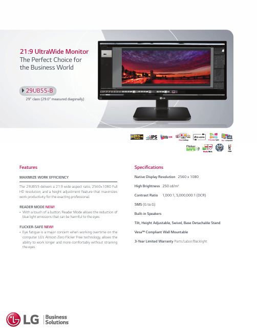
21:9 UltraWide Monitor The Perfect Choice for the Business WorldSpecificationsNative Display Resolution 2560 x 1080 High Brightness 250 cd/m 2Contrast Ratio 1,000:1, 5,000,000:1 (DCR) 5MS (G to G) Built-in SpeakersTilt, Height Adjustable, Swivel, Base Detachable Stand Vesa™ Compliant Wall Mountable3-Year Limited Warranty Parts/Labor/BacklightFeaturesMAXIMIZE WORK EFFICIENCYThe 29UB55 delivers a 21:9 wide aspect ratio, 2560x1080 Full HD resolution, and a height adjustment feature that maximizes work productivity for the exacting professional.READER MODE NEW!•With a touch of a button, Reader Mode allows the reduction of blue light emissions that can be harmful to the eyes.FLICKER-SAFE NEW!•Eye fatigue is a major concern when working overtime on the computer. LG’s Almost-Zero Flicker Free technology, allows the ability to work longer and more comfortably without straining the eyes.29UB55-B29" class (29.0” measured diagonally)THE 4-SCREEN SPLIT DISPLAYS MULTIPLE PROJECTS ON A SINGLE SCREENWith its wide screen ratio, 4 programs can be opened on a single screen for at-a-glance comparison. The 4-Screen Split software includes an auto-fitting function. With a simple drag or a double click, a new window will automatically fit into the marginal room of the screen. The 21:9 screen’s large space is a perfect environment for efficient multi-tasking, and has the ability to open and run an editing program and its source clip folder without minimization.The size of the sub-screens, which can be split into 2 to 4 areas, are user-controlled. The 29UB55 is compatible with Mac® and not only provides convenience but also productivity in a single click.*4-Screen Split software requires DVI-D (Dual Link), DisplayPort or HDMI connection with Windows XP/Vista/7/8 or Mac OS® X 10.7 (Lion)/10.8 (Mountain Lion)/10.9 (Maverick).ESSENTIAL WIDESCREEN VIEWINGThe 21:9 ratio is the perfect professional fit for software engineers, sound & video editors, and graphic designers. The widescreen seamlessly connects two separate work areas for easy comparison and multi-tasking on one monitor. Long-range panoramic viewing is full length, without any bezel in the middle or dragging cursors.*21:9 Full Screen or 2560 x1080 Resolution is dependant on content, device,interface or graphic card.OPTIMAL PRODUCTIVITY WHEN USING MICROSOFT® OFFICEThe 29” class display with a 21:9 UltraWide Full HD (2560x1080) provides an efficient environment when using Microsoft® Office programs such as Word, Excel and OneNote. The 21:9 ratio shows 9 more columns compared to conventional 16:9 monitors in Excel, allowing you to see all the content in full view without scrolling to see hidden columns or rows.*21:9 Full Screen or 2560 x1080 Resolution is dependant on content, device, interface or graphic card.MAXIMIZED ERGONOMICS FOR YOUR CONVENIENCEThe 29UB55’s Height Adjustment feature allows up/down monitoradjustments for a comfortable work environment.PERFECT SCREEN FOR A SMALL GROUP COLLABORATIONConnect two devices to a single monitor with Dual Link-up that allows an HDMI + HDMI link. Collaborate with colleagues by simply connecting each other’s devices to this single monitor to share and compare information. Freely show and control the screen while watching your partner doing the same on the opposite side of the monitor. No need to install annoyingprojectors in small rooms or worry if a conference room is occupied.Dual Link-up requires a specific combination of HDMI/DisplayPort/DVI-D (Dual link) connectionwith each device.10.2”1.7”27.7”13.0”14.8”10.6”75mmCONVENIENT AND EASY ACTIONControl with Ease by the Intuitive JoystickThe joystick is a harmony of accurate menu controls and analogue sensitivity. With the fun control of a conventional joystick, its modern technology and design allows for simple control. The intuitive UI has no overlapping and an easy to understand menu selection.EXPERT RECOGNIZED LG IPSWinner of several prestigious awards, L Gs IPS technology is the perfect solution for those who need the most lifelike color expression, bringing the original image alive on the screen.DIMENSIONSComfort Your Eyes with Flicker Safe Certified by TUV and Reader ModeProtect your eyes from exhausting flickers and blue light emmisions. L G’s new Flicker Safe technology reduces the flicker level to almost zero. Activate Reader Mode to minimize harmful blue light emmisions with a simple touch of a hot-key while working, gaming, or watching movies without burdening your eyes.REAR JACK PANELLG Electronics U.S.A., Inc.HE B2B Division2000 Millbrook DriveLincolnshire, IL 60069Customer Service: 888.865.3026/supportContact your LG Regional Sales Representative:Channel: 800.897.8871Hospitality: 800.228.1236E-mail:********************SPEC_29UB55-B_012059_a All screen images are simulated. D imensions and weights are approximate. D esign, specifications, and features subject to change without notice.© Copyright 2016 LG Electronics USA, Inc. All Rights Reserved. “LG Life’s Good” is a registered trademark of LG Corp.ENERGY STAR is a registered trademark of the U.S. Environmental Protection Agency. In Plane Switching is a trademark of LG Philips LCD Ltd. VESA is a trademark of Video Electronics Standards Association. HDMI, the HDMI logo and High-Definition Multimedia Interface are trademarks or registered trademarks of HDMI Licensing LLC.All other product and brand names are trademarks or registered trademarks of their respective companies.Printed in the USA. June 201621:9 UltraWide Monitor The Perfect Choice for the Business World29UB55-B29" class (29.0” measured diagonally)。
科达会议产品及终端的安装调试

2012/12/3
23
TS6610接口介绍
2012/12/3
24
TS5610标清一体终端
2012/12/3
25
TS5610产品概述
型号
觋码能力
编码能力
双流能力
H600-B
1080P60帧
1080P30帧
解码 1080P60+1080P60 1080p60+UXGA60 编码 1080P30+1080P30 1080p30+UXGA60 解码 1080P60+1080P60 1080p60+UXGA60 编码 720P60+720P60 720P60+UXGA60
支持标准H.239双流功能
全觌控操作高清硬件桌面终端,适 用于各类办公桌面。
2012/12/3
29
KDV1000硬件介绍
KDV1000左侧面图
KDV1000史侧面图
2012/12/3
30
软件桌面终端PCMT
3
KDV7920/7820产品概述
H.320、H.323、SIP协议 嵌入式设计,19英寸1.5U机架式结构 支持64k-8M会议速率 高清1080i/P画质、高保真CD级音效 内置标准H.239双流功能 适合大、中型与业会议室部署或 丰富的音频接口 高端视频通信应用。
2012/12/3
35
目录
终端产品介绍
平台产品介绉 外设产品介绍 附录:MCU单板介绍
2012/12/3
36
KDV8000A介绍
2012/12/3
科达KDV7820_KDV7920高清视频会议终端介绍
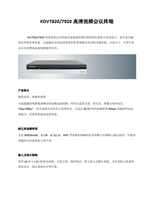
KDV7820/7920高清视频会议终端KDV7820/7920高清视频会议终端具备超强的视音频处理性能和丰富的接口,更具备卓越的协作特性和性能,以超越以往的高清效果给您带来极其真切的沟通体验,可适合大、中型专业会议室部署或高端视频通信应用。
产品特点极致高清、流畅的视频全面超越传统图像清晰度的流畅高清视频,细节呈现更全面、更生动,图像分辨率高达720p/1080p*;更具备超凡的单芯片处理技术,以高达60帧/秒的流畅度和8Mbps的超高码流处理能力,给您带来极致高清体验。
纯正的音频享受支持MPEG4-AAC、G.719、G.722.1C、MP3等宽频音频编码技术和数字音频输入输出特性,可提供清澈纯正的高保真立体声效。
嵌入式设计架构采用19英寸1.5U机架式结构,安装方便、维护简洁。
基于嵌入式操作系统,可有效防止病毒和黑客攻击,保证系统安全和可靠。
卓越的双流协作支持H.239双视频流,可提供高达SXGA/720p/1080p*分辨率的高清双流特性。
强大的网络适应性具备双以太网和多E1接入方式,可实现IP及E1线路的自动冗余备份;内置代理客户端,可实现防火墙/NAT穿越;支持智能抗丢包、动态速率调整、QoS设置、码流平滑等网络优化机制,可全面优化拥塞网络环境下的视频通信效果。
完善的安全机制内置128位AES硬件加密功能,可充分保证会议内容的安全性和保密性;具有本地登陆认证与授权机制,提供合法的本地化管理;可通过H.235网守密码认证机制实现安全的网守注册。
技术参数遵循标准体系标准:H.323、H.320、SIP视频标准:H.263、H.263+、H.264、MPEG-4音频标准:G.711、G.719、G.722、G.722.1 AnnexC/Polycom R Siren14TM、G.728、G.729、MP3、MPEG4-AAC(LC/LD)网络协议:TCP/IP、Telnet、HTTP、FTP、SNMP、DHCP、RTP/RTCP、PPPoE、NTP其他标准:H.221、H.225、H.231、H.235、H.239、H.241、H.242、H.243、H.245、H.281等会议速率64Kbps~8Mbps分辨率活动图像分辨率:1080i/p(1920×1080)*720p(1280×720)4CIF(704×576)CIF(352×288)QCIF(176×144)数据内容分辨率:SXGA(1280×1024)WXGA(1280x800)XGA(1024×768)SVGA(800×600)VGA(640×480)视频接口高清接口:DVI-I(可扩展HDMI、YPbPr、VGA)、HD-SDI可选模块标清接口:复合C端子视频特性内置高清视频矩阵支持视频本地回显可调节亮度、饱和度、对比度等参数支持PAL/NTSC两种制式双流特性支持H.239标准双视频流协议支持单屏双显、双屏双显支持动态双流/静态双流支持带宽调整音频接口数字音频:HDMI、专用数字音频普通音频:卡农(48V幻象供电)、RCA、6.35mm Phone 支持双声道立体声音频特性音频采样频率:48KHzAEC(自动回声消除)ANS(背景噪声抑制)AGC(自动增益控制)自动唇音同步静音与哑音控制控制接口RS485RS232红外遥控网络接口IP:双10/100M以太网专线:可扩展E1、2E1、4E1模块网络特性内置代理客户端实现防火墙/NAT穿越智能抗丢包自动线路备份动态速率调整QoS设置(DiffServ、IP Precedence)MTU值可调IP地址冲突检测网守自动发现和注册PPPoE自动拨号字幕横幅台标支持对其它终端/MCU发送字幕短消息支持滚动、翻页字幕显示支持字幕加载支持横幅叠加横幅背景颜色、字号及字体均可设置支持台标设置组播功能支持会议码流的组播分发终端未加入会议时可组播本地视音频码流可对双视频流进行组播支持组播密码认证VOD点播可登陆录播服务器进行VOD点播支持用户输入参数的保存和快速调用会议功能可创建点对点会议和多点会议支持入会、发言、主席、插话等申请功能支持E.164号、别名、IP地址等呼叫方式可扩展内置MCU功能安全特性基于H.235会议加密流程内置128位AES加密功能会议密码输入本地登陆与授权内置防火墙设置支持H.235网守密码认证管理与诊断支持SNMP标准网管协议可采用遥控器OSD菜单操作支持PC Web登陆实现远程操作支持Telnet、FTP、Web、网管等方式的在线配置和远程升级支持登陆、管理等事件日志功能具备终端自测、环回测试、色带测试、音频测试等功能支持运行状态检测、告警显示和发送可在线显示视音频码率等实时信息支持地址簿管理、实现地址簿导入、导出电气特性整机功耗:≤60W电源:AC(电压100~240V、频率50~60Hz)环境要求接地电阻:≤5Ω工作温度:0~50℃工作湿度:10%~90%(无凝结)气压:86~106kPa物理特性19英寸1.5U标准机架式设计高×宽×深:66mm×442mm×337mm* 1080p分辨率仅在部分型号中提供。
Acer Aspire V15 Nitro Black Edition VN7-591G-792U产

Acer® Aspire V15 Nitro Black Edition VN7-591G-792U $899.99
November 27, 2015
High Level Specifications w 4th Generation Intel® Core™ i7-4720HQ Quad Core Processor 2.6GHz
Let the Aspire V Nitro series be your HD entertainment hub with its impressive 15.6" Full HD Widescreen LED-backlit Display with a true 16:9 cinematic format. Want to take the show to an even bigger screen? Just use the HDMI® port and extend your movies and the highest quality content to your big-screen TV.
Packaging and Documentation Hardware Items AC Power Adapter AC Power Cord
讯飞网维 信号特克 千兆以太网性能测试仪 说明书

SIGNAL TEK™Cable Performance T esterI Gigabit PerformanceQualification – Test toIEEE 802.3 standardsI Selectable PerformanceT esting – qualify performanceof Data, Voice over IP, andIP Video applicationsI Performs Gigabit Ethernetlink establishment test in10 secondsI Data Monitoring to detectintermittent network problemsI Smart Autotest Functiondetects the presence of theSIGNAL TEK remote, activenetwork device or open endedcable and automatically runsthe appropriate test suiteI Intuitive Graphical UserInterface for fast andeasy operationI Internal and USBData Storage –store 20,000 tests internallyor unlimited on USB driveI Prints Easy-to-Read Pass/Fail Qualification ReportsSIGNALTEK™– High-Performance Gigabit Ethernet TestingSIGNALTEK™is the most cost-effective Gigabit Ethernet cableAutotest key to initiate tests from the remote end for one personoperation2.8Љ(7.1cm) 1⁄4VGA Color Display with backlighting for use in low light conditionMulti-color LEDs indicate link status,loopback mode,10/100 and Gigabit device detection,Autotest pass/fail,and battery conditionEasy-to-navigate user interfaceCompact design and soft over-mold sides fit well into any sized handContext sensitive softkeysSingle button cable testingQuick navigation key returns to Job Manager screenSingle button push for active network testing and monitoring Port status function detects 10/100 or Gigabit Ethernet devicesDisplays result for last autotest via red or green LED indicationSIGNAL TEK ™Standard KitCatalog No. 33-974I1 SIGNALTEK ™Near-end and remote-end handset IDEAL INDUSTRIES, INC.03/06Printed in U.S.A.ISO 9001:2000 QMSNo. 33-974SIGNALTEK ™OptionalPower Adapter – 4010-00-0136DESCRIPTION CAT NUMBER SIGNALTEK™ Cable Performance Tester 33-974Replacement cable accessory kit –Contains all original cables in SIGNALTEK™ kit 1219-91-0003RJ45 to 8 head alligator clipK-7920OPTIONALUniversal (120-240V) AC-DC power adapter (1)4010-00-0136。
Nuvoton NK-N9H20用户指南说明书
NK-N9H20User ManualThe information described in this document is the exclusive intellectual property ofNuvoton Technology Corporation and shall not be reproduced without permission from Nuvoton. Nuvoton is providing this document only for reference purposes of NuMicro™ microcontroller based system design. Nuvoton assumes no responsibility for errors or omissions.All data and specifications are subject to change without notice.For additional information or questions, please contact: Nuvoton Technology Corporation.Oct. 02, 2019Table of Contents1Overview (3)2NuDesign HMI-N9H20 Board Introduction (4)2.1NuDesign HMI-N9H20 Jumper Description (8)2.2Pin Assignment for Extended Connectors (11)2.3NuDesign HMI-N9H20/TFT-LCD4.3/SPI2UART(B) PCB Placement (15)2.4NuDesign HMI-N9H20 N9H20K51N’s Control Pin Functions (20)2.5NuDesign HMI-N9H20 BOM (23)2.6NuDesign TFT-LCD4.3 BOM (26)2.7NuDesign SPI2UART(B) BOM (26)3NuDesign HMI-N9H20 Schematics (27)3.1NuDesign HMI-N9H20 Function Blocks Schematic (27)3.2NuDesign HMI-N9H20 N9H20K51N MPU Schematic (28)3.3NuDesign HMI-N9H20 Power Supply Schematic (29)3.4NuDesign HMI-N9H20 Keys and Configuration Schematic (29)3.5NuDesign HMI-N9H20 USB2.0 and SD0 Interface Schematic (30)3.6NuDesign HMI-N9H20 NAND and SPI Flash Memory Schematic (30)3.7NuDesign HMI-N9H20 Headphone Schematic (31)3.8NuDesign HMI-N9H20 JTAG and UART Schematic (32)3.9NuDesign HMI-N9H20 Audio Codec Controller Schematic (33)3.10NuDesign TFT-LCD4.3 LCD Controller Schematic (34)3.11NuDesign SPI2UART(B) Controller Schematic (35)4Revision History (36)Oct. 02, 20191 OverviewThe NK-N9H20 system includes boards NuDesign HMI-N9H20 and NuDesign TFT-LCD4.3 that is a general development board for N9H20K51N series by which users can develop and verify the application program easily. The NuDesign HMI-N9H20 includes Audio controller, USB 2.0 HS Device controller, SPI to UART controller, 24-bit LCD controller and integrated 32MB DDR2 memory, SRAM and external device with DMA request and ack.Oct. 02, 20192 NuDesign HMI-N9H20 Board IntroductionThe following figures show the NuDesign HMI-N9H20 development board, in which the front and back integrated 32-bit microcontroller embeds an outstanding CPU core ARM926EJ-S, runs up to 192MHz, with 16KB I-cache, 16 KB D-cache and MMU,32KB embedded SRAM and 12KB IBR(Internal Boot ROM) for booting from USB and SPI FLASH; Audio controller NAU8822A is a low power, high quality CODEC for portable and general purpose audio applications, it includes drivers for speaker, headphone, and differential or stereo line outputs, and integrates preamps for stereo differential microphones, significantly reducing external component requirements. The board also supports several extended connections. Users can use it to develop and verify applications to emulate the real behavior.Figure 2-1 NuDesign HMI-N9H20 PCB Board (Front)Figure 2-2 NuDesign HMI-N9H20 PCB Board (Back) Oct. 02, 2019Figure 2-3 NuDesign TFT-LCD4.3 PCB Board (Front) Oct. 02, 2019Figure 2-4 NuDesign TFT-LCD4.3 PCB Board (Back) Oct. 02, 2019Oct. 02, 2019 Figure 2-5 NuDesign SPI2UART(B) PCB Board (Front)2.1 NuDesign HMI-N9H20 Jumper Description2.1.1 Power Source●CON3: 5V DC Adaptor input connector.●CON4 & CON5: External Battery connector.●S3: Power ON/OFF Switch.Source Power port VIN VD33 CON3 Connect to 5V DC Adaptor 5V DC 3.3V S3 VD33 & VD18 Power Enable PWREN of U2 & U3 DC 3.3V Table 2-1 System Power ConnectorsOct. 02, 20192.1.2 LED Indicators2.1.3 Debug Connectors●CON11: Connector in target board NuDesign HMI-N9H20 (U1,●CN2: Connector in target board NuDesign SPI2UART(B) (U2, MINI58FDE)Oct. 02, 20192.1.4 USB Connectors●CON6: Mini USB Connector (USB 2.0 HS Device).2.1.5 Extended Connectors●CON1 and CON2: Show all extended pins in NuDesign HMI-N9H20.2.1.6 Buttons and JUMPER●K1~K6: Key pad button in NuDesign HMI-N9H20.●SW3: Reset button in NuDesign HMI-N9H20.●JP1: System configuration setting in NuDesign HMI-N9H20.2.1.7 Audio Connectors●CON9: Headphone Positive Output or Line Output Right and HeadphoneNegative Output or Line Output Left.Oct. 02, 20192.2 Pin Assignment for Extended ConnectorsThe NuDesign HMI-N9H20 provides the N9H20K5DN target chip functions on board and several extended connectors (NU1, NU2, NU3, NU4, NU5 and NU6) for user applications. The following table is the pin assignment for NuDesign HMI-N9H20.Oct. 02, 2019Oct. 02, 2019Oct. 02, 2019Oct. 02, 20192.3 NuDesign HMI-N9H20/TFT-LCD4.3/SPI2UART(B) PCB Placement The following figure shows the NuDesign each PCB placement.Figure 2-3 NuDesign HMI-N9H20 PCB Placement (Front) Oct. 02, 2019Figure 2-4 NuDesign HMI-N9H20 PCB Placement (Back) Oct. 02, 2019Figure 2-5 NuDesign TFT-LCD4.3 PCB Placement (Front) Oct. 02, 2019Figure 2-6 NuDesign TFT_LCD4.3 PCB Placement (Back) Oct. 02, 2019Oct. 02, 2019 Figure 2-7 NuDesign SPI2UART(B) PCB Placement (Front)2.4 NuDesign HMI-N9H20 N9H20K51N’s Control Pin FunctionsThe following table shows the NuDesign HMI-N9H20 Function Control Pins Assignment.Pin No. GPIO ADC AUDIO CMOS I2C I2S JTAG LCM-80 LCM NAND SD SPI SYSTEM UART USB3 GPB.0 SP_CLKO SD1_D1 UHL_DP14 GPB.14 SDA LMVSYNC5 GPB.13 SCL WDT_RSTn6 GPD.12 SPI0_CLK7 GPD.13 SPI0_CS0nOct. 02, 2019Oct. 02, 2019Table 2-13 N9H20K51N Pin Functions Assignment2.5 NuDesign HMI-N9H20 BOMOct. 02, 2019Oct. 02, 2019Oct. 02, 20192.6 NuDesign TFT-LCD4.3 BOM2.7 NuDesign SPI2UART(B) BOMOct. 02, 20193 NuDesign HMI-N9H20 Schematics3.1 NuDesign HMI-N9H20 Function Blocks SchematicOct. 02, 20193.2 NuDesign HMI-N9H20 N9H20K51N MPU SchematicOct. 02, 20193.3 NuDesign HMI-N9H20 Power Supply Schematic3.4 NuDesign HMI-N9H20 Keys and Configuration Schematic3.5 NuDesign HMI-N9H20 USB2.0 and SD0 Interface Schematic3.6 NuDesign HMI-N9H20 NAND and SPI Flash Memory SchematicOct. 02, 2019Oct. 02, 20193.7 NuDesign HMI-N9H20 Headphone SchematicOct. 02, 20193.8 NuDesign HMI-N9H20 JTAG and UART SchematicOct. 02, 20193.9 NuDesign HMI-N9H20 Audio Codec Controller SchematicOct. 02, 20193.10 NuDesign TFT-LCD4.3 LCD Controller SchematicOct. 02, 20193.11 NuDesign SPI2UART(B) Controller SchematicOct. 02, 2019 4 Revision HistoryImportant NoticeNuvoton Products are neither intended nor warranted for usage in systems or equipment, any malfunction or failure of which may cause loss of human life, bodily injury or severe property damage. Such applications are deemed, “Insecure Usage”.Insecure usage includes, but is not limited to: equipment for surgical implementation, atomic energy control instruments, airplane or spaceship instruments, the control or operation of dynamic, brake or safety systems designed for vehicular use, traffic signal instruments, all types of safety devices, and other applications intended to support or sustain life. All Insecure Usage shall be made at customer’s risk, and in the event that third parties lay claims to Nuvoton as a result of customer’s Insecure Usage, customer shall indemnify the damages and liabilities thus incurred by Nuvoton.。
莫贾V2416A系列迷你型无风扇、振动防护计算机产品介绍说明书

V2416A SeriesCompact,fanless,vibration-proof computers for rolling stock applicationsFeatures and Benefits•Intel Celeron/Core i7processor•Two hot-swappable2.5-inch HDD or SSD storage expansion trays•Dual independent DVI-I displays•2Gigabit Ethernet ports with M12X-coded connectors•2CFast sockets for OS backup•M12A-coded power connector•Compliant with EN50121-4•Complies with all EN50155mandatory test items1•IEC61373certified for shock and vibration resistance•Ready-to-run Debian7,Windows Embedded Standard7,and Windows10Embedded IoT Enterprise2016LTSB platforms•-40to70°C wide-temperature models available•Supports SNMP-based system configuration,control,and monitoring(Windows only)CertificationsIntroductionThe V2416A Series embedded computers are based on the Intel3rd Gen processor and feature4RS-232/422/485serial ports,dual LAN ports,and 3USB2.0hosts.In addition,the V2416A computers provide dual DVI-I outputs and comply with the mandatory test items of the EN50155 standard,making them suitable for a variety of industrial applications.The CFast socket,SATA connectors,and USB sockets provide the V2416A computers with the reliability needed for industrial applications that require data buffering and storage expansion.Most importantly,the V2416A computers come with2hot-swappable storage trays for inserting additional storage media,such as hard disk or solid-state drives,and support hot swapping for convenient,fast,and easy storage replacement. Each storage tray has its own LED to indicate whether or not a storage module is plugged in.The V2416A Series computers come preinstalled with a choice of Linux Debian7or Windows Embedded Standard7to provide programmers with a familiar environment in which to develop sophisticated,bug-free application software at a low cost.1.This product is suitable for rolling stock railway applications,as defined by the EN50155standard.For a more detailed statement,click here:/doc/specs/EN_50155_Compliance.pdfAppearanceFront View Rear ViewSpecificationsComputerCPU V2416A-C2Series:Intel®Celeron®Processor1047UE(2M cache,1.40GHz)V2416A-C7Series:Intel®Core™i7-3517UE Processor(4M cache,up to2.80GHz) System Chipset Mobile Intel®HM65Express ChipsetGraphics Controller Intel®HD Graphics4000(integrated)System Memory Pre-installed4GB DDR3System Memory Slot SODIMM DDR3/DDR3L slot x1Supported OS Linux Debian7Windows Embedded Standard7(WS7E)32-bitWindows Embedded Standard7(WS7E)64-bitStorage Slot CFast slot x2Computer InterfaceEthernet Ports Auto-sensing10/100/1000Mbps ports(M12X-coded)x2Serial Ports RS-232/422/485ports x4,software selectable(DB9male)USB2.0USB2.0hosts x1,M12D-coded connectorUSB2.0hosts x2,type-A connectorsAudio Input/Output Line in x1,Line out x1,M12D-codedDigital Input DIs x6Digital Output DOs x2Video Input DVI-I x2,29-pin DVI-D connectors(female)Digital InputsIsolation3k VDCConnector Screw-fastened Euroblock terminalDry Contact On:short to GNDOff:openI/O Mode DISensor Type Dry contactWet Contact(NPN or PNP)Wet Contact(DI to COM)On:10to30VDCOff:0to3VDCDigital OutputsConnector Screw-fastened Euroblock terminalCurrent Rating200mA per channelI/O Type SinkVoltage24to40VDCLED IndicatorsSystem Power x1Storage x1Hot-swappable2LAN2per port(10/100/1000Mbps)Serial2per port(Tx,Rx)Serial InterfaceBaudrate50bps to921.6kbpsFlow Control RTS/CTS,XON/XOFF,ADDC®(automatic data direction control)for RS-485,RTSToggle(RS-232only)Isolation N/AParity None,Even,Odd,Space,MarkData Bits5,6,7,8Stop Bits1,1.5,2Serial SignalsRS-232TxD,RxD,RTS,CTS,DTR,DSR,DCD,GNDRS-422Tx+,Tx-,Rx+,Rx-,GNDRS-485-2w Data+,Data-,GNDRS-485-4w Tx+,Tx-,Rx+,Rx-,GNDPower ParametersInput Voltage12to48VDCPower Connector M12A-coded male connectorPower Consumption(Max.) 3.3A@12VDC0.82A@48VDCPower Consumption40W(max.)Physical CharacteristicsHousing AluminumIP Rating IP30Dimensions(with ears)250x86x154mm(9.84x3.38x6.06in)Dimensions(without ears)275x92x154mm(10.83x3.62x6.06in)Weight4,000g(8.98lb)Installation DIN-rail mounting(optional),Wall mounting(standard) Protection-CT models:PCB conformal coating Environmental LimitsOperating Temperature Standard Models:-25to55°C(-13to131°F)Wide Temp.Models:-40to70°C(-40to158°F) Storage Temperature(package included)-40to85°C(-40to185°F)Ambient Relative Humidity5to95%(non-condensing)Standards and CertificationsEMC EN55032/24EMI CISPR32,FCC Part15B Class AEMS IEC61000-4-2ESD:Contact:6kV;Air:8kVIEC61000-4-3RS:80MHz to1GHz:20V/mIEC61000-4-4EFT:Power:2kV;Signal:2kVIEC61000-4-5Surge:Power:2kVIEC61000-4-6CS:10VIEC61000-4-8PFMFRailway EN50121-4,IEC60571Railway Fire Protection EN45545-2Safety EN60950-1,IEC60950-1Shock IEC60068-2-27,IEC61373,EN50155Vibration IEC60068-2-64,IEC61373,EN50155DeclarationGreen Product RoHS,CRoHS,WEEEMTBFTime332,173hrsStandards Telcordia(Bellcore),GBWarrantyWarranty Period3yearsDetails See /warrantyPackage ContentsDevice1x V2416A Series computerInstallation Kit8x screw,for storage installation2x storage key1x wall-mounting kit8x washer,for HDD/SSDDocumentation1x document and software CD1x quick installation guide1x warranty cardDimensionsOrdering InformationModel Name CPU Memory(Default)OS CFast(CTO)Backup CFast(CTO)Hot-SwappableSSD/HDD Tray(CTO)Operating Temp.ConformalCoatingV2416A-C2Celeron1047UE4GB or optional1(Optional)1(Optional)2(Optional)-25to55°C–V2416A-C2-T Celeron1047UE4GB or optional1(Optional)1(Optional)2(Optional)-40to70°C–V2416A-C2-CT-T Celeron1047UE4GB or optional1(Optional)1(Optional)2(Optional)-40to70°C✓V2416A-C7i7-3517UE4GB or optional1(Optional)1(Optional)2(Optional)-25to55°C–V2416A-C7-T i7-3517UE4GB or optional1(Optional)1(Optional)2(Optional)-40to70°C–V2416A-C7-CT-T i7-3517UE4GB or optional1(Optional)1(Optional)2(Optional)-40to70°C✓V2416A-C2-W7E Celeron1047UE4GB8GB1(Optional)2(Optional)-25to55°C–V2416A-C2-T-W7E Celeron1047UE4GB8GB1(Optional)2(Optional)-40to70°C–V2416A-C7-T-W7E Core i7-3517UE4GB8GB1(Optional)2(Optional)-40to70°C–Accessories(sold separately)Battery KitsRTC Battery Kit Lithium battery with built-in connectorCablesCBL-M12XMM8PRJ45-BK-100-IP67M12-to-RJ45Cat-5E UTP gigabit Ethernet cable,8-pin X-coded male connector,IP67,1mCBL-M12(FF5P)/Open-100IP67A-coded M12-to-5-pin power cable,IP67-rated5-pin female M12connector,1mConnectorsM12A-5PMM-IP685-pin male circular threaded D-coded M12USB connector,IP68M12X-8PMM-IP678-pin male X-coded circular threaded gigabit Ethernet connector,IP67M12A-5P-IP68A-coded screw-in sensor connector,female,IP68,4.05cmM12A-8PMM-IP678-pin male circular threaded A-codes M12connector,IP67-rated(for field-installation)Power AdaptersPWR-24270-DT-S1Power adapter,input voltage90to264VAC,output voltage24V with2.5A DC loadPower CordsPWC-C7AU-2B-183Power cord with Australian(AU)plug,2.5A/250V,1.83mPWC-C7CN-2B-183Power cord with two-prong China(CN)plug,1.83mPWC-C7EU-2B-183Power cord with Continental Europe(EU)plug,2.5A/250V,1.83mPWC-C7UK-2B-183Power cord with United Kingdom(UK)plug,2.5A/250V,1.83mPWC-C7US-2B-183Power cord with United States(US)plug,10A/125V,1.83mAntennasANT-WDB-ANF-0407 2.4/5GHz,omni-directional antenna,4/7dBi,N-type(male)Wall-Mounting KitsV2400Isolated Wall Mount Kit Wall-mounting kit with isolation protection,2wall-mounting brackets,4screwsDIN-Rail Mounting KitsDK-DC50131DIN-rail mounting kit,6screws©Moxa Inc.All rights reserved.Updated Jun12,2019.This document and any portion thereof may not be reproduced or used in any manner whatsoever without the express written permission of Moxa Inc.Product specifications subject to change without notice.Visit our website for the most up-to-date product information.。
KDV7x10终端及遥控器的使用资料

KDV7610/7210整机外型-后面板
• KDV7610/7210
KDV7610/7210整机外型-后面板说明
• • • • • • • • • • • • • • • 1 2 3 4 5 6 7 8 9 10 11 12 13 14 15 KAI 科达音频专用输入接口,暂无功能 MIC 卡农音频输入接口.支持多钟界面话筒及鹅颈式话筒输入 AUDIO L 左声道线性音频输出接口 AUDIO L 左声道线性音频输入接口 AUDIO R 右声道线性音频输出接口 AUDIO R 右声道线性音频输入接口 VIDEO Out 复合视频C端子输出接口 VIDEO IN 复合视频C端子输入接口 VIDEO IN 复合视频C端子输入接口 VGA VGA输出接口,用于连接显示设备. LAN RJ45以太网接口 RS-232 RS-232串口,用于设备的维护和外置摄像头控制 USB2.0 USB2.0扩展口,暂无功能 Power 设备电源开关 220V/AC 电源接口
TS7610/TS7210终端及遥控器的使用
课程适用范围说明
本课程适用以下人员学习: 客服工程师、服务中心技术支持工程师; 视频会议系统维护、操作人员。
课程提纲
一、终端介绍
1、KDV7610/7210终端介绍
2、终端的简单安装
二、使用遥控器进行终端配置
三、使用遥控器操作会议 四、终端软件升级
接地点
KDV7610/7210简单连接图
•
KDV7610/7210最简安装连接图
终端的简单安装
会议摄像机的连线说明:(以SONY EVI-D70P为例) • 图像翻转开关:使用摄像机时设置为OFF,当摄像机铞顶安装在天花板 上时设置为ON; • 详细说明请参见《EVI-D70P使用说明书》; 图像翻转开关 摄像机视频输出 摄像头控制线 摄像头电源线
Ruckus美国优科无线产品介绍大全

RUCKUS美国优科无线产品介绍大全《产品目录》无线控制器- ZoneDirector 3000系列 (3)无线控制器 - ZoneDirector 1000系列 (10)无线接收器 - 室内11n ZoneFlex 7942 (15)无线接收器 - 室外11n ZoneFlex 7942-OT (21)无线接收器 - 室内11g ZoneFlex 2942 (27)无线接收器 - 室外11g ZoneFlex 2942-OT (35)无线接收器 - 室外大功率(500mw)ZoneFlex 2741 (40)无线接收器- 室内双频11n ZoneFlex 7962 (48)无线接收器- 室外双频11n ZoneFlex 7762 (54)无线接收器- 室内大功率(500mw)ZoneFlex 2942-FB (60)无线接收器- 室外大功率(500mw)ZoneFlex 2942-FBOT (65)无线网络管理系统– FlexMaster (72)无线控制器- ZoneDirector 3000系列Ruckus ZoneDirector 3000是首个企业级智能无线局域网系统,它在一个很低的总体拥有成本上,提供了一个安全、可靠,同时又易于扩展的无线局域网解决方案。
Ruckus ZoneDirector 3000的设计理念力求简洁而易用,通过一个中央点,其最多可以管理500台ZoneFlex 802.11b/g和802.11n,以及室内室外的智能无线AP。
完全不像传统的无线局域网那么昂贵、复杂、难以部署,对任何一个需要高性能无线局域网而又期望其易于实施和管理的企业来说,选用ZoneDirector 3000都是再合适不过的了。
ZoneDirector 3000集成了很多高级的功能,诸如智能天线操纵,智能无线网状结构,以及动态无线安全等,这些都是你在其他的WLAN系统中见不到的。
Ruckus ZoneDirector 3000可以由非无线网络专业人员进行部署和操作,安装非常快速简便。
ThinkPad 平板电脑 2 无线信息说明书
ThinkPad Regulatory NoticeAbout this manualThis manual contains regulatory information for ThinkPad®Tablet2.It provides wireless information for the following countries:•Chile•India•Korea•Malaysia•Mexico•Morocco•Nigeria•Pakistan•Saudi Arabia•Serbia•South Africa•Taiwan•Thailand•UAENotice for Users in Chile(Nota para Uso en Chile)For model:BCM94330LGASubsecretaria de Telecomunicaciones(SUBTEL)Certificado ORD.NO.6705/DFRS06272/F-50For model:T77H395Subsecretaria de Telecomunicaciones(SUBTEL)Certificado ORD.NO.7493/DFRS06736/F-50Notice for users in IndiaFor model:BCM94330LGA2233/2012/WRLO2234/2012/WRLOFor model:T77H3952336/2012/WRLO1Notice for users in KoreaFor model:BCM94330LGANote that this device has been certified for residential use and may be used in any environment.Notice for users in MalaysiaFor model:BCM94330LGAComplies with SIRIMRegistration number:SQASI/TA/12/1724For model:T77H395Complies with SIRIMRegistration number:SQASI/TA/12/1831Notice for users in Mexico(Nota para uso en Mexico)For model:BCM94330LGARadio802.11a/b/g/n and BluetoothCOFETEL RCPBRBC12–1311For model:T77H395Module Transceptor RFID13.56MHz NFCCOFETEL RCPFOT712–1144Advertensia:En Mexico la operación de este equipo estásujeta a las siguientes dos condiciones:(1)es posible que este equipo o dispositivo no cause interferencia perjudicial y(2)este equipo o dispositivo debe aceptar cualquier interferencia, incluyendo la que pueda causar su operación no deseadaNotice for users in MoroccoFor models:BCM94330LGA and T77H395The operation of this product in the radio channel2(2417MHz)is not authorized in the following cities:Agadir,Assa-Zag,Cabo Negro,Chaouen,Goulmima,Oujda, Tan Tan,Taourirt,Taroudant and Taza.2The operation of this product in the radio channels4,5,6,and7(2425-2442 MHz)is not authorized in the following cities:Aéroport Mohamed V,Agadir, Aguelmous,Anza,Benslimane,Béni Hafida,Cabo Negro,Casablanca,Fès, Lakbab,Marrakech,Merchich,Mohammédia,Rabat,Salé,Tanger,Tan Tan, Taounate,Tit Mellil,Zag.Due to the channel restrictions above,the operation of this product using thefat channel mode(40MHz of channel bandwidth)is not allowed at the2.4GHz frequency band.3Notice for users in NigeriaFor models:BCM94330LGA and T77H395Notice for users in PakistanFor model:BCM94330LGAPakistan Telecommunication Authority(PTA)approved. 4Notice for users in Saudi ArabiaFor model:BCM94330LGA5For model:T77H3956Notice for users in SerbiaFollowing adapters have been approved by Ratel:•BCM94330LGA•T77H395Notice for users in South AfricaNotice for users in TaiwanFor models:BCM94330LGA and T77H3957根據NCC低功率電波輻射性電機管理辦法規定:第十二條經型式認證合格之低功率射頻電機,非經許可,公司、商號或使用者均不得擅自變更頻率、加大功率或變更原設計之特性及功能。
Gigabit Ethernet Fiber Media Converter 产品说明说明书
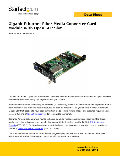
Gigabit Ethernet Fiber Media Converter Card Module with Open SFP SlotProduct ID: ET91000SFP2CThe ET91000SFP2C Open SFP Fiber Media Converter card module converts and extends a Gigabit Ethernet connection over fiber, using the Gigabit SFP of your choice.A versatile solution for connecting an Ethernet (1000Base-T) network to remote network segments over a fiber backbone, the media converter features an open SFP slot that lets you choose the MSA-Compliant Gigabit SFP that best suits your fiber connection mode (single / multi-mode) and distance requirements (see our full line of Gigabit transceivers for compatible solutions).Designed for applications where multiple chassis-powered media converters are required, this Gigabit media converter ships as a card module that can easily be installed into the 20 Slot, 2U Rackmount Chassis (ETCHS2U). For standalone operation this Gigabit media converter can also be purchased as a standard Open SFP Media Converter (ET91000SFP2).The fiber to Ethernet converter offers simple plug-and-play installation, while support for full-duplex operation and Jumbo Frame support provides efficient network operation.Backed by a 2-year warranty and free lifetime technical support.Certifications, Reports and Compatibility Applications•Mount multiple media converter cards into a rack mount chassis•Cost-effective way to extend/bridge networks using fiber cabling •Provides connectivity to a user or network segment that is in an isolated area of a large complex or in another building altogether•Perfect for secure connections required by government agencies where EMI is not acceptable•Connect traffic control/monitoring systems at extreme distances to the main office•Extend network connectivity to remote areas of stadiums,auditoriums or other venuesFeatures•Media Converter card module designed for installation into the ETCHS2U Rackmount Chassis•Open SFP slot supports MSA-Compliant Single / Multi-Mode Gigabit SFPs at varying distances•Advanced features include Link-loss forwarding, remote monitor status, two frame lengths•Supports full or half-duplex operation•Easy to use and install•Jumbo Frame supportWarranty 2 YearsHardware Chipset ID Marvell - 88E1111Industry Standards IEEE 802.3ab 1000BASE-TIEEE 802.3z 1000BASE-LXIEEE 802.3z 1000BASE-SXPoE NoWDM NoPerformance Auto MDIX YesFiber Operating Mode Half/Full-DuplexMaximum Data Transfer Rate 1.25 GbpsMTBF65, 000 HoursConnector(s)Local Unit Connectors 1 - RJ-45 Female1 - SFP Slot FemaleSpecial Notes / Requirements Note Fiber data transfer speeds and distances are dependent onthe SFP used (sold separately)Power Center Tip Polarity PositiveInput Current 1 AInput Voltage12V DCPlug Type MPower Consumption (In Watts)< 8WPower Source Not Included (not required for standard applications) Environmental Humidity10~90% RH (Non-Condensing)Operating Temperature0°C to 60°C (32°F to 140°F)Storage Temperature-10°C to 70°C (14°F to 158°F)PhysicalCharacteristicsProduct Height0.8 in [2.1 cm]Product Length 5.6 in [14.2 cm]Product Width 2.9 in [74 mm]Weight of Product 3.9 oz [110 g]PackagingInformationPackage Height 1.1 in [27 mm]Package Length7.3 in [18.5 cm]Package Width 5.1 in [13 cm]Shipping (Package) Weight 6.5 oz [184 g]What's in the Box Included in Package 1 - Fiber Media Converter1 - Instruction Manual Product appearance and specifications are subject to change without notice.。
IP网络电话技术

淮安信息职业技术学院 信息与通信工程系 王 威
IP电话的一些产品介绍
CISCO Unified IP电话7941G-GE
CISCO Unified IP电话7941G-GE基本参数 网络接口:一个RJ-45接口 主要功能: 该电话提供了对语音留言的直接访问功能 网络协议: DHCP(动态主机设置协议 ,用于动态分配 IP地址); TFTP(简单文件传输协议,是TCP/IP协 议族中的一个用来在客户机与服务器之间 进行简单文件传输 的协议 ) 电力规格: CP-PWR-CUBE-3
IP电话的传输与宽带网接入技术
• IP电话的传输网络包括:
1)IP数据专网(如局域网): 宽带局域网、光纤局域网、城域网、分组无线 局域网; 2)电信公网: 由接入网(AN)、国内骨干网、国际骨干网组 成的Internet
IP电话的传输与宽带网接入技术
• 城域网传输: 这是IP电话传输的基本方式。局域网是一个 覆盖有限地理范围,具有高速率和高质量数据传 输能力、简单的介质访问控制方法,可连接各种 数据通信终端并具有结构简单、易于管理等特点 的通信网络。 局域网朝高速方向发展,其中高速局域网有 ATM(异步传输模式)和FDDI(光纤分布式数据接 口 )/CDDI(铜线分布式数据接口 ) 注:FDDI-一种速率为100Mb/s,采用多模光纤作 为传输媒介的高性能光纤令牌环(token ring)局 域网
IP电话的技术标准与协议
3、ETSI(欧洲电信标准协会)
ETSI工作主要基于ITU-T和IETF的活动并与之协 调,规定了一套业务操作性要求,确定接口和功 能方面的体系结构,对呼叫控制程序、信息流和 协议进行规定,研究端到端的服务质量参数、 E.164地址与IP地址间的转换;解决计费和安全问 题,保证IP网络终端用户与PSTN、ISDN、GSM间的 通讯;提供H.323系列建议和现有电路交换网络通 讯的标准
科达KDV7920高清终端介绍及配置
2020/11/2
42
终端诊断
诊断结果:
测试结果
Reply from 172.16.0.1:byte=64 time<1ms TTL=64 Reply from 172.16.0.1:Destination host unreachable
2020/11/2
33
终端视频设置
视频设置: 系统设置——高级设置——视频设置——视频输入输出;首先
设置终端各视频接口的信号对应矩阵。
2020/11/2
34
终端视频设置
设置视频矩阵 设置输入输出接口类型 设置输出接口对应信号
2020/11/2
35
终端视频设置
设置视频输出制式:点击视频设置界面的“下一步”进入制式设置:
按 再按
键出现呼叫界面:输入对端IP地址及呼叫码率, 实现点对点呼叫。
10.65.0.1
2020/11/2
25
遥控器使用实例
设置应答方式: 终端对于呼叫的应答方式有三种: 1)自动:无需任何操作自动应答来自远端的呼叫 2)手动:需要手动操作应答远端呼叫 3)免打扰:远端不能呼入 应答方式的设置步骤: 菜单—系统设置—普通设置—应答模式
1. 将 DVI- YPbPr 转接头连接到 DVI2 输入接口; 2. 用色差分量(YPbPr)视频线,连接终端 DVI2 转接头的 Y(绿)、Pb(蓝)、Pr (红) 输入口和摄像机的色差分量输出口 (Component);请按照接口颜色正确 连接视 频线,否则,可能导致无画面显示或显示异常。 3、用摄像机控制线,连接摄像机 2 的控制 IN 口摄像机 1 的控制 OUT 口。
WG-7972工业网络应用主板说明书
User Manual Ver0.1 WG-7972工业网络应用主板支持Intel Core™i7/i5/i3/CPU,Q170芯片组1个DDR4 DIMM插槽,最高支持16 GB板贴4G/8G DDR4 内存支持三显示1 x VGA,2 x HDMI2 x RS232 DB9 COM, 2 x RS232 Pin-Header,2 x RS232/RS485 Pin-Header3 x GbE LAN、2 x USB2.0,4 x USB3.0 HOST2 x HDMI显示,最高分辨率4K4 x PCIE 扩展槽,4 x 标准7P SATA座, 1 x M2PCIE, 1 x MINI PCIE内建RTC和Watchdog支持ATX电源输入ContentsChapter 1 引言 (1)1.1 简介 (1)1.2 安全要求 (1)Chapter 2 硬件规格说明 (3)2.1 机械安装尺寸 (2)2.2 产品图片 (4)2.3 性能参数 (4)2.4 WG-7972 I/O接口图 (6)2.5 接口定义及跳线使用说明 (7)2.4.1板载接口一览表 (7)2.4.2跳线使用说明 (9)2.4.3ATXPWR2电源输入接口定义 (11)2.4.4CPU_FAN接口定义 (11)2.4.5ATXPWR1电源输入接口定义 (11)2.4.6SATA1-4数据接口定义 (12)2.4.7JFP1接口定义 (13)2.4.8SYS_FAN接口定义 (13)2.4.9GPIO1扩展口定义 (13)2.4.10GPIO2扩展口定义 (14)2.4.11F_USB2-3USB2.0扩展串口定义 (14)2.4.12JCOM3-4RS232扩展串口定义 (15)2.4.13JCOM3-4RS232/RS485扩展串口定义 (15)2.4.14LTP1接口定义 (16)2.4.15F_AUDIO接口定义 (16)2.4.16JLAN1-3扩展网口定义 (17)2.4.17COM1-2接口定义 (17)2.4.18RJ45USB1-2网口+USB3.0接口定义 (18)2.4.19双层HDMI显示接口定义 (19)2.4.20USB2.0扩展串口定义 (20)1.1 简介欢迎使用WG-7972工业主板!WG-7972是我公司推出的一款工业主板,具有可靠、易用、低成本等特点。
欧特佳数字无线系统ODWS-1用户手册说明书

Thank you for purchasing the Ortega DIGITAL WIRELESS SYSTEM. Please read this manual carefully before using this product. Keep the manual for future reference.ORTEGADIGITAL WIRELESS SYSTEM ODWS-1Important Safety Instructions CAUTIONThis equipent has been tested and found to comply with the limits for a Class B digital device pursuant to part 15ŁThis device may not cause harmful interference of FCC rules.Operation is subject to the following two conditions: łThis device must accept any interference received including interference that may cause undesired operation.WARNING : TO REDUCE THE RISK OF FIRE OR ELECTRIC SHOCK, DO NOT DISASSEMBLE . NO USER-SERVICEABLE PARTSWARNING : TO REDUCE THE RISK OF FIRE OR ELECTRIC SHOCK, DO NOT EXPOSE THEAPPLIANCE TO RAIN OR MOISTURE.CAUTIONRISK OF ELECTRIC SHOCKDO NOT OPENINSIDE. REFER SERVICING TO QUALIFIEDSERVICE PERSONNEL.CAUTION This equipent has been tested and found to comply with the limits of a Class B digital device pursuant to part 15 of FCC rules. Operation is subject to the following two conditions:(1) This device may not cause harmful interference (2) This device must accept any interference received including interference that may cause undesired operation.interference by one or more of the followingmeasures:- Reorient or relocate the receiving antenna.- Increase the separation between the equipment and receiver.- Connect the equipment into an outlet on a circuit different from that to which the receiver is connected.- Consult the dealer or an experienced radio/TVtechnician for help.- Reorient or relocate the receiving antenna.- Increase the separation between the equipment and receiver.- Connect the equipment into an outlet on a circuit different from that the receiver is connected to.- Consult your dealer or an experienced radio/TV technician for help.1.Observe all instructions carefully in the O2 manual.2.Do not to perform service operations beyond those described in the O2 Manual. Services required when the apparatus has been damaged in any way, such as: is dropped or the enclosure is damaged3.Do not place near heat sources, such as radiators,heat registers, or appliances which produce heat.4.Guard against objects or liquids entering the device. Do not use or place unit near water.5.Clean only with a damp cloth.6.Only use attachments/accessories specified by themanufacturer.WARNING: BEFORE USING YOUR B-BIRD O2DIGITAL WIRELESS SYSTEM,CAREFULLY READ THE OPERATINGINSTRUCTIONS.IMPORTANT SAFETY INSTRUCTIONSPLEASE THESE INSTRUCTIONS IN A SAFE PLACEORTEGA 1.Observe all instructions carefully in the manual.2.Do not perform service operations beyond those described in the manual. Service is required when the apparatus has been damaged in any way, such as:-Liquid has been spilled over or objects have fallen into the apparatus-The unit has been exposed to rain or moisture-The unit does not operate normally or changes in performance are significant.- The unit is dropped or the enclosure is damaged 3.Do not place near heat sources, such as radiators, hot plates, or appliances which produce heat. 4.Prevent objects or liquids from entering the device. Do not use or place the unit near water.5.Clean only with a damp cloth.6.Only use attachments/accessories specified by the manufacturer. STOREPRODUCT INTRODUCTIONB-BIRD O2 guitar system features digital wireless technology that delivers incredible audio quality, simple setup, and is extremely reliable for any gigging musicians. It delivers a full 20 Hz - 20K Hz frequency response, so you’ll hear your guitar tone in great detail with only 5ms of latency. This wireless system operates at 2.4GHz ISM band for crystal clear broadcasting ensuring the integrity of your signal on stage and covers 100 feet of range without any signal dropout. The li-ion batteries help makes the O2 wireless system environmentally friendly that can last up to 5 hours per charge. The chassis is made out of a durable ABS plastic that can withstand the rigors of touring and the harshest of climates. This wireless is a perfect fit for any pedal board thanks to its simplistic, and compact design. So, go wireless with the B-BIRD O2 system. It’ll declutter the stage and offers freedom in motion7.Prolonged listening at high volume levels may cause irreparable hearing loss and/or damage. Always be sure to practice “safe listening.”7.Prolonged listening at high volume levels may cause irreparable hearing loss and/or damage. Always be sure to practice “safe listening.” The ORTEGA DIGITAL WIRELESS SYSTEM features digital wireless technology delivering incredible audio quality, a simple setup, and is extremly reliable for any gigging musician. It supports a full 20Hz-20kHz frequency range, so you will hear your guitar tone in great detail. This wireless system operates at 2.4GHz ISM band for crystal clear broadcasting ensuring the integrity of your signal on stage and covering 100 feet of range without any signal dropout. The li-ion batteries make the ORTEGA DIGITAL WIRELESS SYSTEM environmentally friendly. It can last up to 5 hours per charge. The chassis is made out of a durable ABS plastic that can withstand the issues of touring and the harshest climates. This wireless system is a perfect fit to any pedal board thanks to its simplistic and compact design. Go wireless with the ORTEGA DIGITAL WIRELESS System. It will declutter the stage and offer a higher freedom of movement.PRODUCT INTRODUCTIONQUICK START DIAGRAM 1.Transmitter plugs into the Guitar (you instruments),the receiver plugs into the effects pedal, AMP, Audio, etc.2.Turn on the Transmitter and the receiver, the A B C D LED will indicate how much volume of the battery, each LED means about 25% of the battery volume. for example,if A B C D LED all light on,it means about 100% full volume left,and the like if only A LED lights on means about 25% of the battery volume left. if the A LED turn red and flashing,it means the batteryororQUICK START DIAGRAM1.Prepare: Transmitter is plugged into the Guitar (your instrument), the receiver is connected to your effect pedal, AMP, Audio, etc.2. LED indication: Turn on the transmitter and the receiver. The four LEDs: A, B, C and D indicate the battery life with each LED standing for about 25% of the power left. For example: If the four LEDs all light up, it 100% of the battery charge is left. Ifonly the A LED lights up, about 25% of the battery charge is left. If the A LED turns red and flashes, the battery is low and needs to be charged.is in low volume and you have to charge.3.Channel choosing,O2 systems’pre-set channel is 3.Charging, put the USB plug into the transmitter and channel A,after showing battery volume the A LED will flash,it indicates making pairs,if transmitter and receiver connected successfully the channel LED will stop flashing and turn solid green. if environment interuption happens, you can click the “C” button to choose receiver meanwhile, the A B C D LED will light on orderly according to the batteries’ volume. another channel. 3. Channel Selection: The system‘s preset channel is channel A. After indicating the battery life, the A LED will flash. If the transmitter and the receiver are connected successfully the channel LED ( of the channel you have selected) will stop flashing and turns solid green. If there is an interruption through the environment, you can click on the “Channel” button to choose another channel.4. Charging: Put the micro USB plugs into the transmitter and receiver. After that, hook up the standard USB end with a energy souce like your PC or a powerbank. While charging the four LEDs will all light up indicating the status of the overall battery charge.1.Power – Slide Switch to turn on/off TRANSMETER/RECEIVER BASIC OPERATION2.Channel Select - Align TRANSMITTER and RECEIVER channels.1. Power – Slide Switch to turn on/off TRANSMITTER/RECEIVER2. Channel Select - Align TRANSMITTER and RECEIVER channels.BASIC OPERATION4.Transmitter Audio signal indicator LED 3.Battery LED and Channel LEDWhen Power is on, the A LED will flash toindicate the pre-set channel is A.Click the switch to select the channel Follow the diagram below to set up the channel , meanwhile the audio signal indicator LED will flash O2 syetem at first power on,the lighting LED number indicate the battery volume,if 3 LED light on,it means 3*25%=75% battery volume left.The A LED have 2 function,one is channel A,the other is turn to red flashing in low volume and have to be charged.to indicate the channel.AB CD Click the switch to select a channel (A B C or D).Follow the diagram below to set up the channel. The audio signal indicator LED will flash to indicate the selected channel.Q & A Four channels The O2 wireless guitar system has four different channels, and can use up to 4 pair of systems at the same time. When your band plays for guitar, bass, keyboard and other instruments, O2 can set up different channels for them to prevent signal interference. When there is only one player, thedifferent channel function can also be used for him/her to prevent interferences from different frequency bands of routers or other WIFI devices. Generally we recommend to use Channel APortable Plug-and- Play design O2 wireless system uses a portable design; both the receiver and the receiver are plug-and-play design. It is very convenient for fast switching among guitar, bass, amplifiers, effect pedal and other audio equipments. It provides more flexibility in adjusting the equipments.One Transmitter and multiple Receivers When using a transmitter, you can use multiplereceivers. For example, if you want to connect a guitarQ & AFour channelsThe ORTEGA DIGITAL WIRELESS SYSTEM has four different channels and can operate with 4 active pairs of systems at the same time. When your band uses several pairs for guitar, bass, keyboard and one other instrument, you can set up 4 different channelspreventing signal interferences. When there is only one player, the different channel function can also be used to prevent interferences from different frequency bands of routers or other WIFI devices. Generally we recommend to use Channel A.Portable Plug-and-Play design The ORTEGA DIGITAL WIRELESS SYSTEM features a portable format; both the transmitter and the receiver are designed for plug-and-play. The system is very convenient for fast switching among guitar, bass, amplifiers, effect pedals and other audio equipment. One Transmitter and multiple ReceiversWhen using a transmitter, you can use multiple receivers. For example: If you want to connect a guitarto two amplifiers or connect to effect pedal and pedal tuner, you need just use multiple receivers with setting up to be the same channel.O2 Receiver Since O2 is the 2.4 GHz wireless system, please avoid putting the receiver close to other signal emitting devices. It is recommended that your O2 receiver keep a distance of more than 3 meters from the other 2.4 GHz transmitter and WIFI router.Auto sleep/wake up mode The auto sleep/wake up mode will start when over 10 seconds there is still on signal input,it make you more silent when you stop playing,meanwhile, it also help you to save the battery volume.Power charge There is a “Y” shape cable in the package. It can charge the transmitter and receiver at the same time.The voltage output is 5V. The channel A LED never turn to red for normal use. Red A LED light flashing means low battery which requires immediate power charge.to two amplifiers, you just need to use multiple receivers being set to the same channel as your transmitter.ReceiverAs the system is working with 2.4GHz, please avoid putting the receiver close to other signal emitting devices. It is recommended that your receiver keeps a distance of more than 3 meters from other 2.4GHz transmitters and WIFI routers.Auto sleep/wake up modeThe auto sleep/wake up mode will activate when there is no signal input for over 10 seconds. On the one hand this feature cuts the signal and prevents you from unwanted noise on stage and on the other hand it also helps you to save battery life.Power charge You find a “Y” shaped cable in the package. It can charge the transmitter and receiver at the same time. The voltage output is 5V. The channel A LED never turns to red during normal use. If the A LED light is flashing this means low battery life which requires immediate power charge.or need more distance for using, you can change the antenna's angle and adjust it to be the best condition.Supportive pickup and musical instrument O2 wireless system can works for passive guitar and active pickup, piezoelectric acoustic guitar pickup, piezoelectric violin pickup. Transmitter is better to connect to the instrument.Please avoid connecting it to distortion effect pedal or high power output interface which may incur the timbre B port USB only works for charging function, does not support firmware upgrade.Being confronted with interferrence from other devices or needing a higher reach on stage, you can change the antenna's angle and adjust it to the best condition.Pickups and preamp systems The ORTEGA DIGITAL WIRELESS SYSTEM works with passive and active electronics, piezoelectric acoustic guitar pickups and piezoelectric violin pickups. Please connect the transmitter directly to your instrument. Avoid connecting it to distortion/overdrive pedals or high power output interfaces.USB USB only works for charging the battery and does not support firmware upgrades.Ortega - a brand of Roland Meinl Musikinstrumente GmbH & Co. KG | Musik-Meinl-Str.1 | 91468 Gutenstetten, Germany | 。
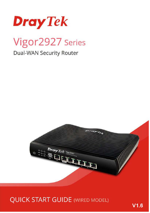
DrayTek Vigor927双广域网安全路由器快速入门指南(适用于有线型号)说明书
Vigor2927Dual-WAN Security Router Quick Start Guide(for Wired Model)Version: 1.6Firmware Version: V4.4.2(For future update, please visit DrayTek web site)Date: November 23, 2022Intellectual Property Rights (IPR) InformationCopyrights © All rights reserved. This publication contains information that is protected by copyright. No part may be reproduced, transmitted, transcribed, stored ina retrieval system, or translated into any language without writtenpermission from the copyright holders.Trademarks The following trademarks are used in this document:●Microsoft is a registered trademark of Microsoft Corp.●Windows, 8, 10, 11 and Explorer are trademarks of Microsoft Corp.●Apple and Mac OS are registered trademarks of Apple Inc.●Other products may be trademarks or registered trademarks of theirrespective manufacturers.Safety Instructions and ApprovalSafety Instructions ●Read the installation guide thoroughly before you set up the router.●The router is a complicated electronic unit that may be repaired only beauthorized and qualified personnel. Do not try to open or repair therouter yourself.●Do not place the router in a damp or humid place, e.g. a bathroom.●Do not stack the routers.●The router should be used in a sheltered area, within a temperaturerange of +5 to +40 Celsius.●Do not expose the router to direct sunlight or other heat sources. Thehousing and electronic components may be damaged by direct sunlight or heat sources.●Do not deploy the cable for LAN connection outdoor to preventelectronic shock hazards.●Keep the package out of reach of children.●When you want to dispose of the router, please follow local regulationson conservation of the environment.Warranty We warrant to the original end user (purchaser) that the router will be free from any defects in workmanship or materials for a period of two (2) yearsfrom the date of purchase from the dealer. Please keep your purchasereceipt in a safe place as it serves as proof of date of purchase. During thewarranty period, and upon proof of purchase, should the product haveindications of failure due to faulty workmanship and/or materials, we will, atour discretion, repair or replace the defective products or components,without charge for either parts or labor, to whatever extent we deemnecessary tore-store the product to proper operating condition. Anyreplacement will consist of a new or re-manufactured functionallyequivalent product of equal value, and will be offered solely at ourdiscretion. This warranty will not apply if the product is modified, misused,tampered with, damaged by an act of God, or subjected to abnormal workingconditions. The warranty does not cover the bundled or licensed software ofother vendors. Defects which do not significantly affect the usability of theproduct will not be covered by the warranty. We reserve the right to revisethe manual and online documentation and to make changes from time totime in the contents hereof without obligation to notify any person of suchrevision or changes.EU Declaration of ConformityWe DrayTek Corp. , office at No.26, Fushing Rd., Hukou, Hsinchu Industrial Park, Hsinchu 303, Taiwan, declare under our soleresponsibility that the product●Product name: Dual-WAN Security Router●Model number: Vigor2927●Manufacturer: DrayTek Corp.●Address: No.26, Fushing Rd., Hukou, Hsinchu Industrial Park,Hsinchu 303, Taiwan.is in conformity with the relevant Union harmonisation legislation:EMC Directive 2014/30/EU , Low Voltage Directive 2014/35/EU, ErP 2009/125/EC and RoHS 2011/65/EU with reference to thefollowing standardsStandard Version / Issue dateEN 550322015+AC:2016 class BEN 61000-3-22014 Class AEN 61000-3-32013EN 550242010+A1:2015EN 62368-12014+A11:2017EN IEC 63000:2018 2018EC No. 1275/2008 2008Hsinchu2nd January, 2020Calvin Ma / President .Signature)(Legal (place) (date)Declaration of ConformityWe DrayTek Corp. , office at No.26, Fushing Rd., Hukou, Hsinchu Industrial Park, Hsinchu 303, Taiwan, declare under our soleresponsibility that the product●Product name: Dual-WAN Security Router●Model number: Vigor2927●Manufacturer: DrayTek Corp.●Address: No.26, Fushing Rd., Hukou, Hsinchu Industrial Park, Hsinchu 303, Taiwan●Importer: CMS Distribution Ltd: Bohola Road, Kiltimagh, Co Mayo, Irelandis in conformity with the relevant UK Statutory Instruments:The Electromagnetic Compatibility Regulations 2016 (SI 2016 No.1091), The Electrical Equipment (Safety) Regulations 2016 (SI2016 No.1101), The Ecodesign for Energy-Related Products and Energy Information (Amendment) (EU Exit) Regulations 2019 (SI2019 No.539) and The Restriction of the Use of Certain Hazardous Substances in Electrical and Electronic Equipment Regulations2012 (SI 2012 No. 3032) with reference to the following standards:Standard Version / Issue dateEN 550322015+AC:2016 class BEN 61000-3-22014 Class AEN 61000-3-32013EN 550242010+A1:2015EN 62368-12014+A11:2017EN IEC 63000:2018 2018EC No. 1275/2008 2008Hsinchu2nd January, 2020Calvin Ma / President .Signature)(Legal (place) (date)Regulatory InformationFederal Communication Commission Interference StatementThis equipment has been tested and found to comply with the limits for a Class B digital device, pursuant to Part 15 of the FCC Rules. These limits are designed to provide reasonable protection against harmful interference in a residential installation. This equipment generates, uses and can radiate radio frequency energy and, if notinstalled and used in accordance with the instructions, may cause harmful interference to radio communications. However, there is no guarantee that interference will not occur in a particular installation. If this equipment does cause harmful interference to radio or television reception, which can be determined by turning the equipment off and on, the user is encouraged to try to correct the interference by one of the following measures:● Reorient or relocate the receiving antenna.● Increase the separation between the equipment and receiver.● Connect the equipment into an outlet on a circuit different from that to which the receiver is connected.●Consult the dealer or an experienced radio/TV technician for help.This device complies with Part 15 of the FCC Rules. Operation is subject to the following two conditions: (1) This device may not cause harmful interference, and(2) This device may accept any interference received, including interference that may cause undesired operation.Company nameABP International Inc.Address 13988 Diplomat Drive Suite 180 Dallas TX 75234 ZIP Code 75234E-mail *******************USA Local RepresentativeContact PersonMr. Robert MesserTel.19728311600Caution:Any changes or modifications not expressly approved by the party responsible for compliance could void the user's authority to operate this equipment.*The external power supply used for each product will be model dependent.1 2 3 4 5 6 7 8 9 A Manufacturer CWT CWT CWT CWT CWT APD APD APD APD BAddressNo. 222, Sec. 2, Nankan Rd.,Lujhu Township, Taoyuan County 338, Taiwan No. 222, Sec. 2, Nankan Rd.,Lujhu Township, Taoyuan County 338, Taiwan No. 222, Sec. 2, Nankan Rd.,Lujhu Township, Taoyuan County 338, Taiwan No. 222, Sec. 2, Nankan Rd.,Lujhu Township, Taoyuan County 338, Taiwan No. 222, Sec. 2, Nankan Rd.,Lujhu Township, Taoyuan County 338, TaiwanNo.5, Lane 83, Lung-Sou St., Taoyuan City 330, Taiwan No.5, Lane 83, Lung-Sou St., Taoyuan City 330, Taiwan No.5, Lane 83, Lung-Sou St., Taoyuan City 330, Taiwan No.5, Lane 83,Lung-Sou St., Taoyuan City 330, Taiwan2ABB012F UK 2ABB018F UK 2ABL024F UK 2ABL030F UK 2ABN036F UK WA-12M12FG WB-18D12FG WA-24Q12FG WA-36A12FG C Model identifier 2ABB012F EU 2ABB018F EU 2ABL024F EU 2ABL030F EU 2ABN036F EU WA-12M12FK WB-18D12FK WA-24Q12FK WA-36A12FK D Input voltage 100~240V 100~240V 100~240V 100~240V 100~240V 100~240V 100~240V 100~240V 100~240VInput AC frequency 50/60Hz 50/60Hz 50/60Hz 50/60Hz 50/60Hz 50/60Hz 50/60Hz 50/60Hz 50/60Hz EOutput voltage DC 12.0V 12.0V 12.0V 12.0V 12.0V 12.0V 12.0V 12.0V 12.0VF Output current 1.0A1.5A2.0A2.5A3.0A 1.0A 1.5A 2.0A 3.0AG Output power 12.0W 18.0W 24.0W 30.0W 36.0W 12.0W 18.0W 24.0W 36.0W H Average activeefficiency 84.9% 86.2% 87.6% 87.8% 89.8% 83.7% 85.4% 88.6% 88.2% IEfficiency at low load 10%73.6% 78.0% 81.3% 83.3% 83.7% 74.5% 80.5% 86.4% 85.4% J No-load powerconsumption0.07W 0.07W 0.07W 0.07W 0.07W 0.07W 0.10W 0.07W 0.10WExternal power supply (Power Adapter) information. For more update, please visit .T a b l e o f C o n t e n t s1. Package Content (1)2. Panel Explanation (2)2.1 Vigor2927 (2)3. Hardware Installation (4)3.1 Network Connection (4)3.2 Wall-Mounted Installation (5)4. Software Configuration (6)5. Customer Service (13)Be a Registered Owner (13)Firmware & Tools Updates (13)1. P a c k a g e C o n t e n tTake a look at the package content. If there is anything missed or damaged, please contact DrayTek or dealer immediately. Besides, the content is subject to the real package.Vigor RouterQuick Start GuideRJ-45 Cable (Ethernet)The type of the power adapter depends on the country that the router will be installed. * The maximum power consumption is 22 Watt .UK-type Power AdapterEU-type Power AdapterUSA/Taiwan-type Power AdapterAU/NZ-type Power Adapter2. P a n e l E x p l a n a t i o n2.1 V i g o r 2927No. LEDStatusExplanationOff The router is powered off.ACT Blinking The router is powered on and running normally.On Internet connection is ready. OffInternet connection is not ready. WAN2/WAN1 Blinking The data is transmitting.On USB device is connected and ready for use. OffNo USB device is connected. USB1/USB2 Blinking The data is transmitting. On The DMZ function is enabled. OffThe DMZ function is disabled. DMZ Blinking The data is transmitting.On The QoS function is active. QoS Off The QoS function is inactive. On The VPN tunnel is active. Off VPN services are disabledVPNBlinking Traffic is passing through VPN tunnel. On The Web Content Filter is active. (It is enabled from Firewall >> General Setup ). (1)WCFOffWCF is disabled.WAN1,WAN2 / P6 On The port is connected. OffThe port is disconnected. Left LED Blinking The data is transmitting.On The port is connected with 1000Mbps. Right LED OffThe port is connected with 10/100Mbps. LAN P1-P5 On The port is connected. OffThe port is disconnected. Left LED Blinking The data is transmitting.On The port is connected with 1000Mbps. (2)Right LEDOff The port is connected with 10/100MbpsNo.Interface Description(3) FactoryResetRestore the default settings. Usage: Turn on the router(ACT LED is blinking). Press the hole and keep for more than5 seconds. When you see the ACT LED begins to blink rapidlythan usual, release the button. Then the router will restartwith the factory default configuration.(4) USB Connecter for a USB device (for 3G/4G USB Modem or printer or thermometer).WAN1 Connecter for local network devices or modem for accessing Internet.WAN2 / P6 Connecter for local network devices or modem for accessing Internet.It is a switchable port. It can be used for LAN connection or WAN connection according to the settings configured in WUI.(5)LAN P1-P5 Connecters for local network devices.PWR Connecter for a power adapter. (6)ON/OFF PowerSwitch.3.H a r d w a r e I n s t a l l a t i o nThis section will guide you to install the router through hardware connection and configure the router’s settings through web browser.Before starting to configure the router, you have to connect your devicescorrectly.3.1N e t w o r k C o n n e c t i o n1.Connect the cable Modem/DSL Modem/Media Converter to any WAN port ofrouter with Ethernet cable (RJ-45).2.Connect one end of an Ethernet cable (RJ-45) to one of the LAN ports of therouter and the other end of the cable (RJ-45) into the Ethernet port on yourcomputer.3.Connect one end of the power adapter to the router’s power port on therear panel, and the other side into a wall outlet.4.Power on the device by pressing down the power switch on the rear panel.5.The system starts to initiate. After completing the system test, the ACT LEDwill light up and start blinking. (For the detailed information of LED status,please refer to section 2. Panel Explanation)3.2 W a l l -M o u n t e d I n s t a l l a t i o nVigor router has keyhole type mounting slots on the underside.1. Drill two holes on the wall. The distance between the holes shall be 168mm.2.Fit screws into the wall using the appropriate type of wall plug.Note The recommended drill diameter shall be 6.5mm (1/4”).3. When you finished about procedure, the router has been mounted on thewall firmly.4. S o f t w a r e C o n f i g u r a t i o nTo access Internet, please finish basic configuration after completing the hardware installation.The Quick Start Wizard is designed for you to easily set up your router for Internet access. You can directly access the Quick Start Wizard via Web User Interface. Make sure your PC connects to the router correctly.NoteYou may either simply set up your computer to get IP dynamically from the router or set up the IP address of the computer to be the same subnet as the default IP address of Vigor router192.168.1.1. For the detailed information, please refer to - Trouble Shooting of the user’s guide.Open a web browser on your PC and type http://192.168.1.1. A pop-up window will open to ask for username and password. Please enter “admin/admin” as the Username/Password and click Login.NoteIf you fail to access to the web configuration, please go to “Trouble Shooting” on User’s Guide for detecting and solving your problem.Now, the Main Screen will pop up. Click Wizards>>Quick Start Wizard.NoteThe home page will change slightly in accordance with the router you have.If your router can be under an environment with high speed NAT, theconfiguration provide here can help you to deploy and use the router quickly. The first screen of Quick Start Wizard is entering login password. After typing the password, please click Next .On the next page as shown below, please select the WAN interface that you use. If Ethernet interface is used, please choose WAN1 or WAN2; if wireless 2.4G/5G connection is used, please choose WAN3 or WAN4; if 3G USB modem is used, please choose WAN5 or WAN6. Then click Next for next step. Each WAN interface will bring up specific configuration page.Click Next. You have to select the appropriate Internet access type (PPPoE, PPTP, L2TP, Static IP or DHCP) according to the information from your ISP.Here we take PPPoE and DHCP modes for WAN connection as examples.F o r P P P o E C o n n e c t i o n1.Choose WAN1 as WAN Interface and click the Next button; you will get thefollowing page.2.Select PPPoE and click Next to get the following page.3.Enter the Username/Password provided by your ISP. Then click Next forviewing the summary of such connection.4.Click Finish. A page of Quick Start Wizard Setup OK will appear.Then,the system status of this protocol will be shown.5.Now, you can enjoy surfing on the Internet.F o r D H C P C o n n e c t i o n1.Choose WAN1 as WAN Interface and click the Next button; you will get thefollowing page.2.Select DHCP and click Next to get the following page.3.Enter the hostname and / or MAC address provided by your ISP. Then clickNext for viewing summary of such connection.4.Click Finish. A page of Quick Start Wizard Setup OK will appear.Then,the system status of this protocol will be shown.5.Now, you can enjoy surfing on the Internet.5.C u s t o m e r S e r v i c eIf the router cannot work correctly after trying many efforts, please contact your dealer for further help right away. For any questions, please feel free to send ***************************.B e a R e g i s t e r e d O w n e rWeb registration is preferred. You can register your Vigor router viahttps://.F i r m w a r e&T o o l s U p d a t e sDue to the continuous evolution of DrayTek technology, all routers will beregularly upgraded. Please consult the DrayTek web site for more information on newest firmware, tools and documents.https://。
